EP4451186A2 - Zentralkabinensteuerungssysteme und -verfahren - Google Patents
Zentralkabinensteuerungssysteme und -verfahren Download PDFInfo
- Publication number
- EP4451186A2 EP4451186A2 EP24166883.9A EP24166883A EP4451186A2 EP 4451186 A2 EP4451186 A2 EP 4451186A2 EP 24166883 A EP24166883 A EP 24166883A EP 4451186 A2 EP4451186 A2 EP 4451186A2
- Authority
- EP
- European Patent Office
- Prior art keywords
- central controller
- lavatory
- controller
- various embodiments
- passenger
- Prior art date
- Legal status (The legal status is an assumption and is not a legal conclusion. Google has not performed a legal analysis and makes no representation as to the accuracy of the status listed.)
- Pending
Links
Images


Classifications
-
- G—PHYSICS
- G06—COMPUTING OR CALCULATING; COUNTING
- G06Q—INFORMATION AND COMMUNICATION TECHNOLOGY [ICT] SPECIALLY ADAPTED FOR ADMINISTRATIVE, COMMERCIAL, FINANCIAL, MANAGERIAL OR SUPERVISORY PURPOSES; SYSTEMS OR METHODS SPECIALLY ADAPTED FOR ADMINISTRATIVE, COMMERCIAL, FINANCIAL, MANAGERIAL OR SUPERVISORY PURPOSES, NOT OTHERWISE PROVIDED FOR
- G06Q10/00—Administration; Management
- G06Q10/06—Resources, workflows, human or project management; Enterprise or organisation planning; Enterprise or organisation modelling
- G06Q10/063—Operations research, analysis or management
- G06Q10/0631—Resource planning, allocation, distributing or scheduling for enterprises or organisations
- G06Q10/06315—Needs-based resource requirements planning or analysis
-
- B—PERFORMING OPERATIONS; TRANSPORTING
- B64—AIRCRAFT; AVIATION; COSMONAUTICS
- B64D—EQUIPMENT FOR FITTING IN OR TO AIRCRAFT; FLIGHT SUITS; PARACHUTES; ARRANGEMENT OR MOUNTING OF POWER PLANTS OR PROPULSION TRANSMISSIONS IN AIRCRAFT
- B64D11/00—Passenger or crew accommodation; Flight-deck installations not otherwise provided for
- B64D11/0007—Devices specially adapted for food or beverage distribution services
-
- B—PERFORMING OPERATIONS; TRANSPORTING
- B64—AIRCRAFT; AVIATION; COSMONAUTICS
- B64D—EQUIPMENT FOR FITTING IN OR TO AIRCRAFT; FLIGHT SUITS; PARACHUTES; ARRANGEMENT OR MOUNTING OF POWER PLANTS OR PROPULSION TRANSMISSIONS IN AIRCRAFT
- B64D11/00—Passenger or crew accommodation; Flight-deck installations not otherwise provided for
- B64D11/06—Arrangements of seats, or adaptations or details specially adapted for aircraft seats
-
- B—PERFORMING OPERATIONS; TRANSPORTING
- B64—AIRCRAFT; AVIATION; COSMONAUTICS
- B64D—EQUIPMENT FOR FITTING IN OR TO AIRCRAFT; FLIGHT SUITS; PARACHUTES; ARRANGEMENT OR MOUNTING OF POWER PLANTS OR PROPULSION TRANSMISSIONS IN AIRCRAFT
- B64D11/00—Passenger or crew accommodation; Flight-deck installations not otherwise provided for
- B64D11/02—Toilet fittings
-
- B—PERFORMING OPERATIONS; TRANSPORTING
- B64—AIRCRAFT; AVIATION; COSMONAUTICS
- B64D—EQUIPMENT FOR FITTING IN OR TO AIRCRAFT; FLIGHT SUITS; PARACHUTES; ARRANGEMENT OR MOUNTING OF POWER PLANTS OR PROPULSION TRANSMISSIONS IN AIRCRAFT
- B64D11/00—Passenger or crew accommodation; Flight-deck installations not otherwise provided for
- B64D11/04—Galleys
-
- G—PHYSICS
- G01—MEASURING; TESTING
- G01F—MEASURING VOLUME, VOLUME FLOW, MASS FLOW OR LIQUID LEVEL; METERING BY VOLUME
- G01F23/00—Indicating or measuring liquid level or level of fluent solid material, e.g. indicating in terms of volume or indicating by means of an alarm
- G01F23/0007—Indicating or measuring liquid level or level of fluent solid material, e.g. indicating in terms of volume or indicating by means of an alarm for discrete indicating and measuring
Definitions
- the present disclosure generally relates to electronic communication systems, and more particularly to central cabin control systems for use an aircraft cabin.
- a connected aircraft may rely on a central controller to manage multiple interior subsystems or perform prognostic health monitoring. These subsystems may be distributed throughout the aircraft. However, these subsystems may utilize sensors that communicate with a local controller (or any other separate controller) of the subsystem that is independent of the central controller. In this regard, sensors of various subsystems are connected to separate systems and controllers.
- a water system may connect to a lavatory and to a galley.
- a water system is typically considered an independent system from a lavatory system.
- water system data can help both lavatories and galley products perform better without these products adding additional sensors to get the same data.
- a cabin control system for an aircraft comprises: a central controller configured to be disposed in the aircraft; a first controller for a first lavatory in electronic communication with the central controller; a second controller for a second lavatory in electronic communication with the central controller; a third controller for a galley insert (GAINs) device in electronic communication with the central controller; a fourth controller for a first water device of a water system in the aircraft, the fourth controller in electronic communication with the central controller; and a control panel in electronic communication with the central controller, the control panel configured to display information corresponding to the first lavatory, the second lavatory, the galley insert (GAINs) device, and the first water device.
- GAINs galley insert
- the central controller is configured to: receive, through a passenger user interface, a lavatory request; analyze an occupancy status of the first lavatory and the second lavatory; and transmit an assigned lavatory to the passenger user interface based on the occupancy status.
- the cabin control system further comprises a fifth controller for a service cart system, the fifth controller configured to track a location of a service cart.
- the central controller is configured to: receive, through a passenger user interface, a lavatory request; analyze an occupancy status of the first lavatory and the second lavatory; analyze a location status of the service cart; and transmit an assigned lavatory to the passenger user interface based on the occupancy status and the location status.
- the cabin control system further comprises a fifth controller for a passenger seat.
- the central controller is configured to receive a seat status corresponding to seat back position of the passenger seat from the fifth controller.
- the central controller is configured to transmit the seat back position of each passenger seat in an aircraft cabin to the control panel.
- the cabin control system further comprises a fifth controller for a second water device of the water system of the aircraft.
- the central controller is configured to: determine that the first water device is low on water; determine that the second water device has an excess water capacity; and command the second water device to transfer a portion of water to the first water device.
- the central controller is further configured to receive a water volume status from the fourth controller and the fifth controller.
- the article of manufacture includes a tangible, non-transitory memory configured to communicate with a processor, the tangible, non-transitory memory having instructions stored thereon that, in response to execution by the processor, cause the processor to perform operations comprising: receiving, by the processor, a request for a specific item in an aircraft cabin; determining, by the processor, a task status of each flight attendant in the aircraft cabin; and transmitting, by the processor, the request to a user device based on the task status.
- the operations further comprise receiving, by the processor, an indication from the user device that the flight attendant is handling the request.
- the operations further comprise updating the task status for the flight attendant in response to receiving the indication.
- the request is transmitted to a plurality of user devices, the plurality of user devices including the user device.
- Each user device in the plurality of user devices can correspond to a respective flight attendant.
- the operations further comprise receiving, by the processor, an indication the flight attendant accepted the request.
- the operations further comprise: receiving, by the processor, a second request for a lavatory from a plurality of lavatories; analyzing, by the processor, a lavatory occupancy data for each lavatory in the aircraft cabin; and assigning, by the processor, an available lavatory in the plurality of lavatories based on the occupancy data.
- the operations further comprise analyzing, by the processor, a location status of each service cart in the aircraft cabin, wherein the assigning the lavatory is based on the occupancy data and the location status of each service cart.
- a central cabin control system for an aircraft cabin comprises: a central controller; and a tangible, non-transitory memory configured to communicate with the central controller, the tangible, non-transitory memory having instructions stored thereon that, in response to execution by the central controller, cause the central controller to perform operations comprising: receiving, by the central controller, a request for a lavatory from a passenger; determining, by the central controller and based on data received from each lavatory in the aircraft cabin, an available lavatory for the passenger; and transmitting, by the central controller and through a network, an indication to the passenger of the available lavatory assigned to the passenger.
- the operations further comprise: receiving, by the central controller a second request for a specific item in the aircraft cabin; determining, by the central controller, a task status of each flight attendant; and transmitting, by the central controller, the request to a user device of a flight attendant.
- the operations further comprise: determining, by the central controller, that a first water device is low on water; determining, by the central controller, that a second water device has excess water; and commanding, by the central controller, the second water device to transfer a portion of water to the first water device.
- references to "a,” “an” or “the” may include one or more than one and that reference to an item in the singular may also include the item in the plural. Further, all ranges may include upper and lower values and all ranges and ratio limits disclosed herein may be combined.
- Disclosed herein is a system architecture that enables the development and integration of a connected aircraft cabin.
- the architecture of the system disclosed herein can be built on a new central controller ecosystem to allow all devices within an aircraft cabin to be networked together in a single central controller managing decisions at a cabin level.
- the microservices capability of the central controller simplifies software development and system integration by allowing multiple applications to be run instead of a standard, monolithic software architecture.
- the system disclosed herein can also allow for advanced features like centralized data loading and a computational grid. These features are not possible with typical independent sub-systems in an aircraft cabin.
- the central controller and architecture disclosed herein can facilitate more efficient management of data. For example, sub-systems with low computational capacity can be loaded on the central controller. This can reduce a total number of parts which reduces costs. Having a common connectivity architecture will simplify integration and reduce non-recurring engineering (“NRE") costs during installation.
- NRE non-recurring engineering
- a central controller for a cabin control system disclosed herein can provide a platform to fully network cabin devices into a single system.
- the interiors controller will use a microservices architecture rather than the more common monolithic architecture.
- This architecture can allow the software to be separated into functional applications. This can allow new functions to be added or other functions to be removed without effecting the other applications.
- This architecture also allows all applications to share information to improve decision making and eliminate redundant lines of communication, in accordance with various embodiments.
- the architecture disclosed herein allows for a redundant fail-safe architecture as information is shared between applications. For example, the central controller may control a lavatory if the local controller for the lavatory becomes non-responsive. Additionally, a local controller for the local controller of the lavatory can become the central controller if the original central controller becomes non-responsive.
- the aircraft 10 comprises a fuselage 12 and wings 16 extending outward from the fuselage 12.
- the wings 16 are designed and configured to produce a lift force in response to a pressure difference generated by the wings 16 exceeding a weight of the aircraft 10.
- the aircraft 10 can comprise landing gear 14 configured to be deployed for landing and used during taxi, or the like.
- the fuselage 12 defines an aircraft cabin 100 therein.
- the aircraft cabin 100 includes seats for passengers, a cockpit for pilot(s), various lavatories, as well as various electronics.
- electronics within an aircraft cabin 100 can include coffee maker(s), passenger service units (PSUs), passenger address (PA) systems, galley equipment, such as beverage makers, cookers, refrigeration units, etc., in-flight entertainment, such as personal video devices (i.e., computers) or the like, satellite systems (e.g., WiFi), or the like.
- the aircraft cabin 100 can further include electronics for sub-systems.
- the aircraft cabin 100 can include various sensors for an evacuation system (i.e., for monitoring the evacuation system), sensors for monitoring an aircraft environment (e.g., a cabin pressure, an air quality, etc.), or the like.
- the present disclosure is not limited in this regard.
- the aircraft cabin 100 includes a cabin control system 200.
- various sub-systems in the aircraft cabin 100 can be electronically coupled to a central controller of the cabin control system 200, as described further herein.
- the cabin control system 200 can facilitate a single central control for all (or a majority) of electronics disposed in, or around, an aircraft cabin 100, as described further herein.
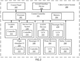
- the cabin control system 200 comprises a central controller 201, a control panel 205, a plurality of sub-systems (e.g., a lavatory 210, a flight attendant user interface (UI) 220, a service cart system 230 (e.g., a service cart tracking system), a passenger UI 240, galley insert (GAIN(s)) devices 250, water devices 260, passenger seat 270 (e.g., a passenger seat device), safety system 280, etc.), each sub-system including a respective controller (e.g., controllers 212, 222, 232, 242, 282 and/or UCN 252, 262, 272).
- a respective controller e.g., controllers 212, 222, 232, 242, 282 and/or UCN 252, 262, 272.
- each UCN 252, 262, 272 can be a local controller, in accordance with various embodiments.
- the cabin control system 200 can be retrofitted on existing aircrafts, in accordance with various embodiments.
- GAINs devices 250 such as a galley oven, a galley boiler, a galley beverage maker, etc. are typically connected to a master galley control unit.
- a cabin control system 200 can be retrofitted into an aircraft cabin 100 without having to replace each GAINs device 250 disposed therein.
- a master control unit of a galley can be replaced with local controllers (e.g., UCN 252) for each respective GAIN device 250, and the local controller (e.g., the UCN 252) can be electronically (e.g., wirelessly or wired) coupled to the central controller 201 for central management as described further herein.
- the central controller 201 can be coupled to a respective master control unit of a galley (e.g., a GAINs device controller) and still be within the scope of this disclosure.
- the GAINs devices 250 can have a server/client relationship with the galley controller, and human machine interface ("HMF") settings for the GAINs devices 250 can reside in the galley controller. Accordingly, new recipe information can be pushed from the central controller 201 to the galley controller and show up in a respective galley controller menu, in accordance with various embodiments.
- HMF human machine interface
- water devices 260 e.g., devices that manage a potable water supply to the lavatory and GAINs devices 250
- a UCN 262 can be retrofitted to provide each respective water device 260 with a local controller (e.g., a UCN 262) to prevent entirely new water devices from being installed and/or to utilize existing architecture.
- UCNs can further be utilized to add features to an aircraft cabin 100 from FIG. 1 .
- UCN 272 and a position sensor can be added to a passenger seat 270.
- the position sensor can be configured to measure a position of a respective passenger seat 270.
- the UCN can transmit position data to the central controller 201 to provide the position information to flight attendants for use in ensuring seat backs are up prior to landing and takeoff, in accordance with various embodiments.
- the central controller 201 is configured as a central network element or hub to various systems and components of the cabin control system 200.
- the central controller 201 comprises a processor (e.g., processor 202).
- the central controller 201 may be implemented as a single controller (e.g., via a single processor 202 and associated memory 204).
- the central controller 201 may be implemented as multiple processors (e.g., a main processor and local processors for various components).
- the central controller 201 can be a general-purpose processor, a digital signal processor (DSP), an application specific integrated circuit (ASIC), a field programable gate array (FPGA) or other programable logic device, discrete gate or transistor logic, discrete hardware components, or any combination thereof.
- the central controller 201 may comprise a processor 202 configured to implement various logical operations in response to execution of instructions, for example, instructions stored on a non-transitory, tangible, computer-readable medium (e.g., memory 204) configured to communicate with the central controller 201.
- System program instructions and/or controller instructions may be loaded onto a non-transitory, tangible computer-readable medium (e.g., memory 204) having instructions stored thereon that, in response to execution by a central controller 201, cause the central controller 201 to perform various operations.
- a non-transitory, tangible computer-readable medium e.g., memory 204 having instructions stored thereon that, in response to execution by a central controller 201, cause the central controller 201 to perform various operations.
- the central controller 201 is electronically coupled to each local controller (e.g., controller 212 for lavatory 210, controller 232 for service cart system 230, each UCN 252 for each GAINs device 250, each UCN 262 for each water device 260, each UCN 272 for each passenger seat 270, and/or the controller 282 for the safety system 280).
- the central controller 201 can be configured to receive data from each respective sub-system and/or command devices in each respective sub-system through a local controller of the respective sub-system as described further herein.
- each local controller can be coupled to one or more sensors.
- a sensor for galley inserts i.e., GAINs devices 250
- GAINs devices 250 can include sensors typically associated with GAINs devices (e.g., power status of a respective device, hot plate status for a coffee maker, etc.).
- a sensor can be a sensor a pressure sensor (e.g., for aircraft cabin pressure, for water pressure, for evacuation system pressure, etc.
- an occupancy sensor e.g., for a lavatory 210, a passenger seat 270, etc.
- a motion sensor for a lavatory 210, a passenger seat 270, etc.
- a position sensor e.g., for a galley or inventory monitoring system, etc.
- a level sensor e.g., for water device 260 of a potable water system, etc.
- humidity sensors e.g., for cabin environment monitoring, etc.
- a UCN in the plurality of UCNs can be coupled to an electrically activated device.
- an electrically activated device can comprise a light indicating the lavatory is occupied or unoccupied.
- an electrically activated device can comprise a warning light to indicate a pressure is low for an evacuation system, a potable water system is near full, or the like. The present disclosure is not limited in this regard.
- the central controller 201 is electronically coupled to an aircraft interface device 206.
- the aircraft interface device 206 can provide flight data to the central controller 201 for distribution to various devices or sub-systems.
- a high-power computation grid can be achieved.
- each interior device within the aircraft cabin 100 from FIG. 1 can utilize a same controller ecosystem (e.g., through the central controller 201).
- the commonality can allow for creation of a high-power computational grid, which can be utilized for prognostic health monitoring and other resource intensive analysis at an interior's aircraft level, in accordance with various embodiments.
- the central controller 201 can be configurable to provide prognostic health monitoring.
- the central controller 201 can report data and results to crew and maintenance teams (e.g., through the aircraft interface device 206 or the like).
- various aircraft data can be sent to a data database for analysis.
- the central controller 201 can allow the prognostic health monitoring to be implemented through an application or the like.
- a separate distinct controller can be added for prognostic health monitoring, in accordance with various embodiments.
- the universal communication device 300 for use in the cabin control system 200 from FIG. 2 (e.g., UCN 252, 262, 272), is illustrated, in accordance with various embodiments.
- the universal communication device 300 comprises a local controller 301.
- the local controller 301 is configured as a central network element or hub to various systems and components of the universal communication device 300.
- local controller 301 comprises a processor (e.g., processor 302).
- local controller 301 may be implemented as a single controller (e.g., via a single processor 302 and associated memory 304).
- local controller 301 may be implemented as multiple processors (e.g., a main processor and local processors for various components).
- the local controller 301 can be a general-purpose processor, a digital signal processor (DSP), an application specific integrated circuit (ASIC), a field programable gate array (FPGA) or other programable logic device, discrete gate or transistor logic, discrete hardware components, or any combination thereof.
- DSP digital signal processor
- ASIC application specific integrated circuit
- FPGA field programable gate array
- the local controller 301 may comprise a processor 302 configured to implement various logical operations in response to execution of instructions, for example, instructions stored on a non-transitory, tangible, computer-readable medium (e.g., memory 304) configured to communicate with the local controller 301.
- System program instructions and/or controller instructions may be loaded onto a non-transitory, tangible computer-readable medium (e.g., memory 304) having instructions stored thereon that, in response to execution by a local controller 301, cause the local controller 301 to perform various operations.
- the universal communication device 300 is configured to communicate with the central controller 201 of a cabin control system 200 (as shown in FIG. 2 ) of an aircraft cabin 100 of an aircraft (as shown in FIG. 1 ) (e.g., via a wired or wireless connection).
- the universal communication device 300 can comprise a wireless port 331 (e.g., a wireless input / output port) and a serial port 332 (e.g., a serial input / output port, a serial output port, or the like).
- the wireless port 331 is a network port that is configured to connect a wireless access point (e.g., of the universal communication device 300), to a wired network (e.g., of the cabin control system 200 from FIG. 2 ).
- a wireless access point e.g., of the universal communication device 300
- a wired network e.g., of the cabin control system 200 from FIG. 2
- such information may be communicated between the universal communication device 300 and the central controller 201 from FIG. 2 by use of a network in the aircraft 10 from FIG. 1 (e.g., through any network, such as a local area network (LAN), or wide area network (WAN) such as the Internet).
- LAN local area network
- WAN wide area network
- the term "network” includes any cloud, cloud computing system, or electronic communications system or method which incorporates hardware and/or software components. Communication among the parties may be accomplished through any suitable communication channels, such as, for example, a telephone network, an extranet, an intranet, internet, point of interaction device (point of sale device, personal digital assistant (e.g., an IPHONE ® device, a BLACKBERRY ® device), cellular phone, kiosk, etc.), online communications, satellite communications, off-line communications, wireless communications, transponder communications, local area network (LAN), wide area network (WAN), virtual private network (VPN), networked or linked devices, keyboard, mouse, and/or any suitable communication or data input modality.
- a telephone network such as, for example, a telephone network, an extranet, an intranet, internet, point of interaction device (point of sale device, personal digital assistant (e.g., an IPHONE ® device, a BLACKBERRY ® device), cellular phone, kiosk, etc.), online communications, satellite communications, off-line communications, wireless
- the system may also be implemented using IPX, APPLETALK ® program, IP-6, NetBIOS, OSI, any tunneling protocol (e.g., IPsec, SSH, etc.), or any number of existing or future protocols.
- IPX IPX
- APPLETALK ® program IP-6
- NetBIOS NetBIOS
- OSI any tunneling protocol (e.g., IPsec, SSH, etc.), or any number of existing or future protocols.
- IPsec IP Security
- SSH Secure Shell
- the central controller 201 of the cabin control system 200 from FIG. 2 and the universal communication device 300 can communicate through a short-range wireless technology standard utilizing radio waves (e.g., Bluetooth ® , or the like).
- a short-range wireless technology standard utilizing radio waves e.g., Bluetooth ® , or the like.
- the present disclosure is not limited in this regard.
- the universal communication device 300 can be electrically coupled to the central controller 201 of the cabin control system 200 (e.g., via the serial port 332 of the universal communication device 300). In various embodiments, the universal communication device 300 can include more than one of the serial port 332. In this regard, the universal communication device 300 can be configured to be coupled to an electrically activated device (e.g., through the wireless port 331 or through the serial port 332). The present disclosure is not limited in this regard.
- the universal communication device 300 further comprises a first analog input 306.
- the first analog input 306 can comprise a fiber connector 313 (e.g., a square connector, a lucent connector, a multi-fiber connector, a straight tip connector, a ferrule connector, a mechanical transfer registered connector, a miniature square connector, a DIN connector, an E2000 connector etc.).
- the fiber connector 313 is a square connector.
- the fiber connector 313 of the first analog input 306 can be configured to interface with fiber connectors typical of aircraft cabins, in accordance with various embodiments.
- the first analog input 306 further comprises a positive port 321 and a negative port 322.
- the positive port 321 is configured to receive a positive pin of an electrical connector and the negative port 322 is configured to receive a negative pin of an electrical connector.
- the first analog input 306 is configured to receive an electrical plug of an alternating current (AC) load, in accordance with various embodiments.
- the universal communication device 300 further comprises a second analog input 308 in accordance with the first analog input 306.
- the second analog input 308 can comprise a fiber connector 314, a positive port 323 and a negative port 324.
- fiber connectors 313, 314 can be standard for aircraft cabin application.
- the universal communication device 300 can include any number of analog inputs.
- the universal communication device 300 can include between two and four analog inputs.
- sub-systems of an aircraft cabin 100 from FIG. 1 can have multiple sensors having analog outputs. Accordingly, the universal communication device 300 can be configured to receive between two and four analog inputs, in accordance with various embodiments.
- the universal communication device 300 can be modular, and utilized in numerous different applications, facilitating economies of scale and/or a reduced part count for products.
- the universal communication device includes a serial peripheral interface (“SPI”) port 311 and an inter-integrated circuit (“I2C”) port 312.
- SPI serial peripheral interface
- I2C inter-integrated circuit
- the universal communication device 300 can be adaptable for use with various communication protocols for use in sub-system of an aircraft cabin 100 of an aircraft 10 from FIG. 1 .
- the universal communication device 300 is configured for smart data loading, as described further herein.
- an SPI port is configured to interface with an SPI connector to form an SPI communication interface for short-distance communication, primarily in embedded systems. Accordingly, the SPI port 311 can have a wide array of application sin an aircraft cabin 100 from Fig. 1 .
- an I2C port is configured to interface with an I2C pin to form an I2C circuit.
- An I2C circuit is a synchronous multi-master/multi-slave (controller/target), packet switched, single-ended serial communication bus.
- I2C circuits are widely utilized in attaching lower-speed peripheral ICs to processors in short-distance, intra-board communication. Accordingly, an I2C port can have a wide array of applications in an aircraft cabin 100 from FIG. 1 .
- the cabin control system 200 disclosed herein can facilitate a lavatory queuing process.
- a lavatory queuing process 400 is illustrated, in accordance with various embodiments.
- the process 400 comprises receiving, by the central controller 201, a request for a lavatory (step 402).
- the request for a lavatory can be received through a passenger user interface (UI) 240.
- UI passenger user interface
- a passenger UI 240 can be available through an in-flight entertainment system (IFE), a personal device (e.g., a smart phone, a computer, etc.), or a passenger service unit (PSU) (e.g., as a button or the like).
- IFE in-flight entertainment system
- PSU passenger service unit
- a controller 242 of the passenger device with the passenger UI 240 can transmit the request to the central controller 201 (e.g., through a network or short-range wireless technology, such as Bluetooth ® ).
- the request for the lavatory will come with a location data for the respective user.
- the passenger location will be known based on the location of the respective device.
- the passenger location may be known based on a location of the device through the passenger UI 240, from data corresponding to the passenger from the passenger UI 240, or the like.
- the present disclosure is not limited in this regard.
- the process 400 further comprises analyzing, by the central controller 201, lavatory occupancy (step 404).
- the central controller 201 can be continuously receiving an occupancy data of each lavatory in the aircraft cabin 100 from FIG. 1 (e.g., from each controller 212 of each lavatory 210).
- the process 400 further comprises analyzing, by the central controller 201, a service cart location data (step 406).
- the central controller 201 can continuously be receiving a location data of each service cart in the aircraft cabin (e.g., from the controller 232 of the service cart system 230).
- the lavatory will not be assigned even if the lavatory is the only lavatory is open.
- the lavatory may be assigned after the service cart is no longer obstructing a respective path, in accordance with various embodiments.
- the central controller 201 can assign a lavatory to a user based on the lavatory occupancy data, a passenger location data, and the service cart location data (step 408).
- a place in queue may be transmitted to a user interface (e.g., through the passenger UI 240 of a respective device of a user).
- lavatory queuing process can further comprise transmitting a notification to the flight team (e.g., through the flight attendant UI 220 or the control panel 205) after a predetermined number of uses of a respective lavatory, instructing that the lavatory be cleaned and restocked.
- the process 450 can facilitate a touchless (or non-touchless) connected lavatory queuing management system thorough a wired or wireless interface.
- the process 450 starts in block 451.
- the process 450 further comprises posting a query, by the central controller 201, to each lavatory in a respective aircraft (step 452).
- step 452 can be performed in predetermined intervals (e.g., every 5 seconds, every 5 milliseconds, every 50 milliseconds, or the like). The present disclosure is not limited in this regard.
- the process 450 further comprises receiving, by the central controller 201 and from a local controller (e.g., controller 212 of lavatory 210), lavatory data.
- lavatory data can include a status of various electronics in the lavatory, such as a faucet status, a soap dispenser status, a trash flap status, a toilet seat status, a toilet cover status, etc.
- the lavatory data can further include an occupied status of the lavatory (i.e., whether the lavatory is occupied).
- the process 450 further comprises updating, by the central controller 201, a lavatory status for each lavatory based on the lavatory data received from the local controller (step 454).
- the central controller 201 in response to a lavatory needing attention, as determined by the central controller 201, the central controller 201 can transmit a notification to a flight crew (e.g., through a flight crew user interface and/or a personal device) (step 455).
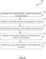
- the process 450 can further comprise receiving, by the central controller a request for a lavatory (step 456).
- step 456 is in accordance with step 402 of process 400 described previously herein.
- the process 450 further comprises performing a sub-process 470 configured to facilitate and manage a lavatory queueing for passengers, as described further herein.
- the process 450 further comprises publishing queue details through a user interface (e.g., through the control panel 205, through a flight attendant UI 220, or the like) (step 457).
- the process 450 can be configured to continuously update a respective user interface, so the crew can be aware of the status of each lavatory on the aircraft 10.
- the process 470 comprises receiving, by a central controller 201, a request for a lavatory from a passenger (step 402).
- the central controller 201 can locate a nearest lavatory.
- the central controller 201 can check the lavatory status of the nearest lavatory and determine whether there are any issues with the nearest lavatory. For example, the central controller can continuously update and store a table corresponding to a status of various electronic devices in each lavatory as shown in Table 1 below.
- Table 1 Example status table generated from process 450 and / or process 470 Faucet Soap Dispenser Trash Flap Toilet Seat Toilet Cover Status to Crew Faulty X X X X Put a Note to use Mechanical Switch on Lav X X Faulty X X X InOp Put a InOP Note on Lav X Normal Soap empty Normal Normal Normal Normal Refill Soap for Lav X Normal Normal Faulty X X InOp Put a InOP Note on Lav X Normal Normal Trash Flap full Normal Normal Empty Trash Flap for Lav X Normal Soap empty Trash Flap full Normal Normal Refill Soap and Empty Trash Flap for Lav X X X X Smoke detected X X Fire in Trash Flap of Lav X X X X Faulty X Put a note in Lav X to move Toilet Seat manually X X X X X Faulty Put a note in Lav X to move Toilet cover
- the central controller 201 can locate a next nearest lavatory (i.e., based on proximity to a passenger seat).
- passengers can be added to a queue for a respective lavatory based on a first to request system (i.e., a passenger that requests prior to a second passenger would be before the second passenger in a respective queue).
- the passenger can be given an estimated time until the lavatory is available based on a place in queue and a pre-determined formula.
- the average time in lavatory in the formula can be updated over time as more data is obtained by the central controller. The present disclosure is not limited in this regard.
- an estimated time of the passenger can be increased based on an average time for special needs passengers.
- the passenger can view his or her place in line through a passenger UI 240 from FIG. 2 .
- the passenger UI 240 can show a position in queue for the passenger, a number of seats in front of the passenger in the queue, or the like.
- the passenger is added to a queue for a lavatory determined by the central controller 201 (step 471).
- a lavatory e.g., based on a nearest lavatory, shortest queue, a weighted determination, or the like.
- the process 470 further comprises determining, by the central controller 201, if a passenger is still waiting for the lavatory (step 472), and updating, by the central controller 201, an estimated time of queue for the passenger (step 473).
- all passengers queue time (i.e., time until the lavatory is available) can be updated for a respective lavatory simultaneously.
- the central controller 201 in response to the central controller 201 detecting a change in lavatory occupancy status (e.g., from occupied to vacant), the central controller 201 can assume that the passenger that was first in queue has used the lavatory.
- the central controller 201 can maintain the passenger in the lavatory queue until step 474 as described further herein or remove the passenger from the queue in response to the lavatory being used.
- the central controller can be configured to transmit a message to the passenger UI 240 querying the passenger to see if the passenger is still waiting.
- the central controller 201 can update the queue accordingly (i.e., to remove the passenger from the queue in step 474 if the passenger indicates "Finished” or maintain the passenger at the passenger's place in queue if the passenger indicates "still waiting").
- An option can be given to passenger through the passenger UI 240 to say that he or she is "Still Waiting” or "Finished” if his or her estimated time is 0. If pressed then a predetermined amount of time (e.g., 3 minutes) can be added to all the estimated times of queue. This process can be repeated every time passenger's estimated time becomes zero.
- a predetermined amount of time e.g., 3 minutes
- the process 470 further comprises removing, by the central controller 201, the passenger from the queue (step 474).
- the passenger can be passively removed from the queue, or actively removed from the queue, the present disclosure is not limited in this regard. For example, if a selected lavatory has been unoccupied for more than 3 minutes continuously, as determined by lavatory data received from the respective lavatory, the passenger at the start of the queue can be removed passively.
- a passenger can confirm through the passenger UI 240 after the passenger utilizes the lavatory and then the central controller 201 can actively remove the passenger from the queue. The present disclosure is not limited in this regard.
- the control panel 205 can include a water management system through a respective user interface disposed thereon.
- the control panel 205 can include a display device and user interface to view data corresponding to the water systems of the aircraft cabin 100 from FIG. 1 .
- each UCN 262 of each water device 260 can continuously transmit data corresponding to water system data of the potable water supply to the lavatory 210 and water system data for each respective GAINs device 250.
- the cabin control system 200 can provide water system status and information to a flight attendant, or other crew member, through a user interface of the control panel 205, in accordance with various embodiments.
- water system status of the potable water supply in the lavatory 210 can be available for use with the GAINs device 250 or vice versa based on a potable water availability.
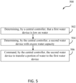
- the process 500 comprises determining, by the central controller 201, that a first water device is low on water (step 502).
- each water device 260 is transmitting a status of a water level (i.e., an amount of available water) to the central controller 201.
- the central controller 201 can determine that a first water device is low on water (i.e., below a threshold volume of water), in accordance with various embodiments.
- the process 500 further comprises determining, by the central controller 201, a second water device with excess water capacity (step 504).
- the central controller 201 can analyze data corresponding to any other water devices 260 based on data received therefrom. Based on the data, the central controller 201 can command the second water device to transfer a portion of water to the first water device (step 506).
- process 500 can facilitate a more efficient sizing of water for an aircraft cabin as the water can be redistributed throughout the water system, in accordance with various embodiments.
- passengers can make flight attendant requests from the passenger UI 240 (e.g., available on an IFE, through a PSU, or on a personal device).
- the IFE and/or a personal device of a passenger can allow more specific request to be made by passengers to flight attendants in accordance with various embodiments.
- a passenger can request ear phones, a pillow, a specific drink available on the menu, etc.
- the central controller can receive a respective request from a passenger and transmit the request to the control panel 205 and/or to a personal device (e.g., through a flight attendant UI 220) of a respective flight attendant (e.g., a flight attendant that is closest to the respective passenger as determined by the central controller 201).
- a personal device e.g., through a flight attendant UI 220
- a respective flight attendant e.g., a flight attendant that is closest to the respective passenger as determined by the central controller 201).
- the central controller 201 can track which flight attendants are handling which requests and assign requests accordingly. In various embodiments, the central controller can send a notification to all flight attendants when a request has been made and a flight attendant can accept a request. In various embodiments, if a flight attendant is already handling a request, the flight attendant may be excluded from a notification of a request when other flight attendants are not handling a request. The present disclosure is not limited in this regard.
- the central controller can track a passenger wait time from when a request is received.
- the central controller 201 can assign tasks based on an order received, in accordance with various embodiments.
- the process 600 comprises receiving, by a central controller 201, a request for a specific item (step 602).
- the specific item can include ear phones, a pillow, a specific item on a drink or food menu, etc.
- the process 600 can further comprise determining, by the central controller 201, a task status of each flight attendant (step 604).
- a status of tasks that have been accepted through the process 600 can be analyzed by the central controller 201.
- the flight attendant UI 220 of each flight attendant can be in continuous communication with the central controller 201 (e.g., through a network or the like). Accordingly, the central controller 201 can monitor each flight attendant's task status and send a notification to flight attendants based on an availability of each respective flight attendant, in accordance with various embodiments.
- the process 600 can further comprise transmitting, by the central controller 201 (e.g., through a network or the like), the request to at least one flight attendant (step 606).
- the request can be assigned, or the flight attendant may have to indicate the flight attendant is accepting the task (i.e., handling the request).
- the present disclosure is not limited in this regard.
- the process 600 can further comprise receiving, by the central controller 201, an indication a flight attendant is handling the request (step 608).
- the central controller 201 can update a respective task status for the flight attendant, in accordance with various embodiments.
- the flight attendant UI 220 for each flight attendant can be utilized for displaying a safety status of the aircraft for flight attendants based on a time period in a respective flight cycle. For example, during landing or takeoff, a passenger seat status (i.e., upright or down position) can be provided to the control panel 205 and/or the flight attendant UI 220 for each flight attendant. In this regard, a flight attendant can quickly check which seat backs are in a down position and inform the passengers to return them to their upright position prior to takeoff or landing, in accordance with various embodiments. Similarly, the flight attendant UI 220 and/or the control panel 205 can be utilized for display of a seat belt status prior to takeoff or landing and/or during turbulence, in accordance with various embodiments.
- data corresponding to the GAINs devices 250 and/or the water devices 260 can be displayed through the control panel 205, a respective flight attendant UI 220, or the like, in accordance with various embodiments.
- health monitoring information can be available to the crew through the control panel 205 and/or a respective flight attendant UI 220.
- crew members can access data corresponding water devices 260 and/or GAINs devices 250 for troubleshooting or the like.
- usage information of the GAINs devices 250 and water devices 260 can further be available through the control panel 205 and/or a respective flight attendant UI 220. In this regard, the usage information can potentially support inventory management, in accordance with various embodiments.
- references to "one embodiment,” “an embodiment,” “various embodiments,” etc. indicate that the embodiment described may include a particular feature, structure, or characteristic, but every embodiment may not necessarily include the feature, structure, or characteristic. Moreover, such phrases are not necessarily referring to the same embodiment. Further, when a particular feature, structure, or characteristic is described in connection with an embodiment, it is submitted that it is within the knowledge of one skilled in the art to affect such feature, structure, or characteristic in connection with other embodiments whether explicitly described. After reading the description, it will be apparent to one skilled in the relevant art(s) how to implement the disclosure in alternative embodiments falling within the scope of the claims.
Landscapes
- Business, Economics & Management (AREA)
- Engineering & Computer Science (AREA)
- Human Resources & Organizations (AREA)
- Aviation & Aerospace Engineering (AREA)
- Entrepreneurship & Innovation (AREA)
- Economics (AREA)
- Strategic Management (AREA)
- Marketing (AREA)
- Physics & Mathematics (AREA)
- Educational Administration (AREA)
- Development Economics (AREA)
- Operations Research (AREA)
- Quality & Reliability (AREA)
- Tourism & Hospitality (AREA)
- Game Theory and Decision Science (AREA)
- General Business, Economics & Management (AREA)
- General Physics & Mathematics (AREA)
- Theoretical Computer Science (AREA)
- Selective Calling Equipment (AREA)
- Small-Scale Networks (AREA)
- Electric Propulsion And Braking For Vehicles (AREA)
Applications Claiming Priority (2)
| Application Number | Priority Date | Filing Date | Title |
|---|---|---|---|
| IN202341021885 | 2023-03-27 | ||
| US18/336,801 US20240330784A1 (en) | 2023-03-27 | 2023-06-16 | Central cabin control systems and methods |
Publications (2)
| Publication Number | Publication Date |
|---|---|
| EP4451186A2 true EP4451186A2 (de) | 2024-10-23 |
| EP4451186A3 EP4451186A3 (de) | 2025-02-26 |
Family
ID=90482543
Family Applications (1)
| Application Number | Title | Priority Date | Filing Date |
|---|---|---|---|
| EP24166883.9A Pending EP4451186A3 (de) | 2023-03-27 | 2024-03-27 | Zentralkabinensteuerungssysteme und -verfahren |
Country Status (1)
| Country | Link |
|---|---|
| EP (1) | EP4451186A3 (de) |
Family Cites Families (3)
| Publication number | Priority date | Publication date | Assignee | Title |
|---|---|---|---|---|
| US20180308037A1 (en) * | 2017-04-25 | 2018-10-25 | The Boeing Company | Vehicle attendant task management systems and methods |
| US20200398988A1 (en) * | 2019-06-19 | 2020-12-24 | Goodrich Corporation | Enhanced potable water system |
| US11958606B2 (en) * | 2020-06-05 | 2024-04-16 | B/E Aerospace, Inc. | Aircraft lavatory systems |
-
2024
- 2024-03-27 EP EP24166883.9A patent/EP4451186A3/de active Pending
Also Published As
| Publication number | Publication date |
|---|---|
| EP4451186A3 (de) | 2025-02-26 |
Similar Documents
| Publication | Publication Date | Title |
|---|---|---|
| US11332250B2 (en) | Integrated aircraft galley and appliance operating system | |
| AU2016266055B2 (en) | Real-time galley power management and fault monitoring system | |
| US8457846B2 (en) | Modular seat actuation control system and communication method | |
| US20160329724A1 (en) | Method for Configurable USB Power Management | |
| CA2790370C (en) | Aircraft seating systems | |
| US20190308579A1 (en) | Seat Sensing and Reporting Apparatus | |
| US10315770B2 (en) | Wireless control systems and methods for aircraft seating systems | |
| EP2082956A2 (de) | System und Verfahren zur elektrisch aktivierten Flugzeugfahrwerksteuerung | |
| JP7109219B2 (ja) | ビークルアテンダントのタスク管理システムおよび方法 | |
| JP7139350B2 (ja) | 機内エンターテイメントシステムによる座席作動制御 | |
| US20240330784A1 (en) | Central cabin control systems and methods | |
| CN115515855A (zh) | 用于经由无线连接控制飞行器座椅及其环境的系统和方法 | |
| CN112308359A (zh) | 预测性飞机客舱服务系统和方法 | |
| CN110316383B (zh) | 座椅传感器阵列和控制器以及具有其的座椅组件 | |
| EP3241748B1 (de) | Sitzmodul mit einem drahtloskommunikationsmodul, fahrzeugsitz mit sitzmodul, flugzeug und verfahren zum betätigen eines sitzmoduls | |
| EP4451186A2 (de) | Zentralkabinensteuerungssysteme und -verfahren | |
| US10836507B2 (en) | Aircraft communication network | |
| EP2853491A1 (de) | Tafel und System zur Flugzeugkabinenverwaltung | |
| CA3027068A1 (en) | Data evaluation system and method for data evaluation in an aircraft | |
| US20180285785A1 (en) | System and method to monitor airplane restroom use | |
| US9907011B2 (en) | Non-transitory computer readable medium, information processing apparatus, and network system for determining relay unit based on loading information and useable-area of user | |
| EP4439324A1 (de) | Universeller kommunikationsknoten | |
| US20240331461A1 (en) | Universal communication node | |
| US20180232565A1 (en) | Terminal control system, controller, and terminal control method | |
| CN119284174A (zh) | 一种飞机智慧客舱系统 |
Legal Events
| Date | Code | Title | Description |
|---|---|---|---|
| PUAI | Public reference made under article 153(3) epc to a published international application that has entered the european phase |
Free format text: ORIGINAL CODE: 0009012 |
|
| STAA | Information on the status of an ep patent application or granted ep patent |
Free format text: STATUS: THE APPLICATION HAS BEEN PUBLISHED |
|
| AK | Designated contracting states |
Kind code of ref document: A2 Designated state(s): AL AT BE BG CH CY CZ DE DK EE ES FI FR GB GR HR HU IE IS IT LI LT LU LV MC ME MK MT NL NO PL PT RO RS SE SI SK SM TR |
|
| PUAL | Search report despatched |
Free format text: ORIGINAL CODE: 0009013 |
|
| AK | Designated contracting states |
Kind code of ref document: A3 Designated state(s): AL AT BE BG CH CY CZ DE DK EE ES FI FR GB GR HR HU IE IS IT LI LT LU LV MC ME MK MT NL NO PL PT RO RS SE SI SK SM TR |
|
| RIC1 | Information provided on ipc code assigned before grant |
Ipc: B64D 11/04 20060101ALI20250120BHEP Ipc: B64D 11/02 20060101ALI20250120BHEP Ipc: G05D 9/12 20060101ALI20250120BHEP Ipc: G01F 15/00 20060101ALI20250120BHEP Ipc: B64D 11/06 20060101ALI20250120BHEP Ipc: B64D 11/00 20060101ALI20250120BHEP Ipc: G06Q 10/0631 20230101AFI20250120BHEP |
|
| STAA | Information on the status of an ep patent application or granted ep patent |
Free format text: STATUS: REQUEST FOR EXAMINATION WAS MADE |
|
| STAA | Information on the status of an ep patent application or granted ep patent |
Free format text: STATUS: EXAMINATION IS IN PROGRESS |
|
| 17P | Request for examination filed |
Effective date: 20250826 |
|
| 17Q | First examination report despatched |
Effective date: 20250924 |