EP4451077A2 - Fernsteuerungsvorrichtung, steuerungssystem, bewegliches objekt, fernsteuerungverfahren und betriebssteuerungsverfahren - Google Patents
Fernsteuerungsvorrichtung, steuerungssystem, bewegliches objekt, fernsteuerungverfahren und betriebssteuerungsverfahren Download PDFInfo
- Publication number
- EP4451077A2 EP4451077A2 EP24164477.2A EP24164477A EP4451077A2 EP 4451077 A2 EP4451077 A2 EP 4451077A2 EP 24164477 A EP24164477 A EP 24164477A EP 4451077 A2 EP4451077 A2 EP 4451077A2
- Authority
- EP
- European Patent Office
- Prior art keywords
- moving object
- vehicle
- production step
- control signal
- distance
- Prior art date
- Legal status (The legal status is an assumption and is not a legal conclusion. Google has not performed a legal analysis and makes no representation as to the accuracy of the status listed.)
- Pending
Links
Images





Classifications
-
- G—PHYSICS
- G05—CONTROLLING; REGULATING
- G05D—SYSTEMS FOR CONTROLLING OR REGULATING NON-ELECTRIC VARIABLES
- G05D1/00—Control of position, course, altitude or attitude of land, water, air or space vehicles, e.g. using automatic pilots
- G05D1/20—Control system inputs
- G05D1/22—Command input arrangements
- G05D1/221—Remote-control arrangements
-
- G—PHYSICS
- G05—CONTROLLING; REGULATING
- G05B—CONTROL OR REGULATING SYSTEMS IN GENERAL; FUNCTIONAL ELEMENTS OF SUCH SYSTEMS; MONITORING OR TESTING ARRANGEMENTS FOR SUCH SYSTEMS OR ELEMENTS
- G05B19/00—Program-control systems
- G05B19/02—Program-control systems electric
- G05B19/418—Total factory control, i.e. centrally controlling a plurality of machines, e.g. direct or distributed numerical control [DNC], flexible manufacturing systems [FMS], integrated manufacturing systems [IMS] or computer integrated manufacturing [CIM]
- G05B19/4189—Total factory control, i.e. centrally controlling a plurality of machines, e.g. direct or distributed numerical control [DNC], flexible manufacturing systems [FMS], integrated manufacturing systems [IMS] or computer integrated manufacturing [CIM] characterised by the transport system
- G05B19/41895—Total factory control, i.e. centrally controlling a plurality of machines, e.g. direct or distributed numerical control [DNC], flexible manufacturing systems [FMS], integrated manufacturing systems [IMS] or computer integrated manufacturing [CIM] characterised by the transport system using automatic guided vehicles [AGV]
-
- B—PERFORMING OPERATIONS; TRANSPORTING
- B60—VEHICLES IN GENERAL
- B60W—CONJOINT CONTROL OF VEHICLE SUB-UNITS OF DIFFERENT TYPE OR DIFFERENT FUNCTION; CONTROL SYSTEMS SPECIALLY ADAPTED FOR HYBRID VEHICLES; ROAD VEHICLE DRIVE CONTROL SYSTEMS FOR PURPOSES NOT RELATED TO THE CONTROL OF A PARTICULAR SUB-UNIT
- B60W30/00—Purposes of road vehicle drive control systems not related to the control of a particular sub-unit, e.g. of systems using conjoint control of vehicle sub-units
- B60W30/14—Adaptive cruise control
- B60W30/143—Speed control
-
- B—PERFORMING OPERATIONS; TRANSPORTING
- B60—VEHICLES IN GENERAL
- B60W—CONJOINT CONTROL OF VEHICLE SUB-UNITS OF DIFFERENT TYPE OR DIFFERENT FUNCTION; CONTROL SYSTEMS SPECIALLY ADAPTED FOR HYBRID VEHICLES; ROAD VEHICLE DRIVE CONTROL SYSTEMS FOR PURPOSES NOT RELATED TO THE CONTROL OF A PARTICULAR SUB-UNIT
- B60W30/00—Purposes of road vehicle drive control systems not related to the control of a particular sub-unit, e.g. of systems using conjoint control of vehicle sub-units
- B60W30/14—Adaptive cruise control
- B60W30/16—Control of distance between vehicles, e.g. keeping a distance to preceding vehicle
-
- G—PHYSICS
- G05—CONTROLLING; REGULATING
- G05D—SYSTEMS FOR CONTROLLING OR REGULATING NON-ELECTRIC VARIABLES
- G05D1/00—Control of position, course, altitude or attitude of land, water, air or space vehicles, e.g. using automatic pilots
- G05D1/20—Control system inputs
- G05D1/24—Arrangements for determining position or orientation
- G05D1/247—Arrangements for determining position or orientation using signals provided by artificial sources external to the vehicle, e.g. navigation beacons
- G05D1/249—Arrangements for determining position or orientation using signals provided by artificial sources external to the vehicle, e.g. navigation beacons from positioning sensors located off-board the vehicle, e.g. from cameras
-
- G—PHYSICS
- G05—CONTROLLING; REGULATING
- G05D—SYSTEMS FOR CONTROLLING OR REGULATING NON-ELECTRIC VARIABLES
- G05D1/00—Control of position, course, altitude or attitude of land, water, air or space vehicles, e.g. using automatic pilots
- G05D1/60—Intended control result
- G05D1/69—Coordinated control of the position or course of two or more vehicles
-
- G—PHYSICS
- G05—CONTROLLING; REGULATING
- G05D—SYSTEMS FOR CONTROLLING OR REGULATING NON-ELECTRIC VARIABLES
- G05D1/00—Control of position, course, altitude or attitude of land, water, air or space vehicles, e.g. using automatic pilots
- G05D1/60—Intended control result
- G05D1/69—Coordinated control of the position or course of two or more vehicles
- G05D1/695—Coordinated control of the position or course of two or more vehicles for maintaining a fixed relative position of the vehicles, e.g. for convoy travelling or formation flight
-
- G—PHYSICS
- G05—CONTROLLING; REGULATING
- G05D—SYSTEMS FOR CONTROLLING OR REGULATING NON-ELECTRIC VARIABLES
- G05D1/00—Control of position, course, altitude or attitude of land, water, air or space vehicles, e.g. using automatic pilots
- G05D1/60—Intended control result
- G05D1/69—Coordinated control of the position or course of two or more vehicles
- G05D1/698—Control allocation
- G05D1/6987—Control allocation by centralised control off-board any of the vehicles
-
- G—PHYSICS
- G06—COMPUTING OR CALCULATING; COUNTING
- G06Q—INFORMATION AND COMMUNICATION TECHNOLOGY [ICT] SPECIALLY ADAPTED FOR ADMINISTRATIVE, COMMERCIAL, FINANCIAL, MANAGERIAL OR SUPERVISORY PURPOSES; SYSTEMS OR METHODS SPECIALLY ADAPTED FOR ADMINISTRATIVE, COMMERCIAL, FINANCIAL, MANAGERIAL OR SUPERVISORY PURPOSES, NOT OTHERWISE PROVIDED FOR
- G06Q10/00—Administration; Management
- G06Q10/08—Logistics, e.g. warehousing, loading or distribution; Inventory or stock management
-
- B—PERFORMING OPERATIONS; TRANSPORTING
- B60—VEHICLES IN GENERAL
- B60W—CONJOINT CONTROL OF VEHICLE SUB-UNITS OF DIFFERENT TYPE OR DIFFERENT FUNCTION; CONTROL SYSTEMS SPECIALLY ADAPTED FOR HYBRID VEHICLES; ROAD VEHICLE DRIVE CONTROL SYSTEMS FOR PURPOSES NOT RELATED TO THE CONTROL OF A PARTICULAR SUB-UNIT
- B60W2554/00—Input parameters relating to objects
- B60W2554/80—Spatial relation or speed relative to objects
- B60W2554/802—Longitudinal distance
-
- G—PHYSICS
- G05—CONTROLLING; REGULATING
- G05B—CONTROL OR REGULATING SYSTEMS IN GENERAL; FUNCTIONAL ELEMENTS OF SUCH SYSTEMS; MONITORING OR TESTING ARRANGEMENTS FOR SUCH SYSTEMS OR ELEMENTS
- G05B2219/00—Program-control systems
- G05B2219/30—Nc systems
- G05B2219/31—From computer integrated manufacturing till monitoring
- G05B2219/31014—Synchronization between AGV movement and workpiece treatment chambers
-
- G—PHYSICS
- G05—CONTROLLING; REGULATING
- G05D—SYSTEMS FOR CONTROLLING OR REGULATING NON-ELECTRIC VARIABLES
- G05D2105/00—Specific applications of the controlled vehicles
- G05D2105/45—Specific applications of the controlled vehicles for manufacturing, maintenance or repairing
-
- G—PHYSICS
- G05—CONTROLLING; REGULATING
- G05D—SYSTEMS FOR CONTROLLING OR REGULATING NON-ELECTRIC VARIABLES
- G05D2107/00—Specific environments of the controlled vehicles
- G05D2107/70—Industrial sites, e.g. warehouses or factories
-
- G—PHYSICS
- G05—CONTROLLING; REGULATING
- G05D—SYSTEMS FOR CONTROLLING OR REGULATING NON-ELECTRIC VARIABLES
- G05D2109/00—Types of controlled vehicles
- G05D2109/10—Land vehicles
-
- G—PHYSICS
- G05—CONTROLLING; REGULATING
- G05D—SYSTEMS FOR CONTROLLING OR REGULATING NON-ELECTRIC VARIABLES
- G05D2111/00—Details of signals used for control of position, course, altitude or attitude of land, water, air or space vehicles
- G05D2111/10—Optical signals
Definitions
- the present disclosure relates to a remote control device, a control system, a moving object, a remote control method, and an operation control method.
- Vehicles that automatically run within a production system for manufacturing vehicles by remote control have hitherto been known.
- the present disclosure may be realized by the following aspects.
- the present disclosure may be embodied in various aspects other than the remote control device, the control system, the moving object, the remote control method, and the operation control method described above.
- the present disclosure may be embodied in aspects of methods for producing a remote control device, a control system, and a moving object, computer programs that execute a remote control method and an operation control method, as well as non-transitory storage mediums storing the computer programs, and the like.
- Fig. 1 shows a schematic structure of a control system 1 in the first embodiment.
- the control system 1 includes one or more external sensors, a plurality of moving objects, and a remote control device 5.
- the external sensors are located outside a vehicle 10.
- the external sensors capture the vehicle 10 from outside the vehicle 10.
- Each external sensor is equipped with a communication device (not shown), and can communicate with other devices, such as the remote control device 5 and the like, via wired or wireless communication.
- the external sensor is constituted of a camera.
- a camera 9 as the external sensor (hereafter referred to as an external camera 9) captures images including the vehicle 10, and outputs the captured images as detection results.
- the captured image output from the external camera 9 is also referred to as an "external camera image”.
- the external camera 9 transmits the external camera image to the remote control device 5 together with camera identification information.
- the camera identification information is a unique ID (identifier) assigned to each of a plurality of external cameras 9 to identify them one another, and there is no overlap of camera identification information among the external cameras 9.
- the location and number of the external cameras 9 are determined by considering an imaging range RG (angle of view) or the like of the external cameras 9 to capture the entire image of a track R by the external cameras 9.
- the external cameras 9 are installed so that a first imaging range RG1, which is the imaging range RG of a first external camera 901, and a second imaging range RG2, which is the imaging range RG of a second external camera 902, overlap.
- the first external camera 901 and the second external camera 902 are adjacent to each other.
- the "moving object” means an object capable of moving, and is a vehicle or an electric vertical takeoff and landing aircraft (so-called flying-automobile), for example.
- the moving object is the vehicle 10.
- the vehicle may be a vehicle to run with a wheel or may be a vehicle to run with a continuous track, and may be a passenger car, a track, a bus, a two-wheel vehicle, a four-wheel vehicle, a construction vehicle, or a combat vehicle, for example.
- the vehicle includes a battery electric vehicle (BEV), a gasoline automobile, a hybrid automobile, and a fuel cell automobile.
- the vehicle 10 is configured to be capable of running by unmanned driving.
- the "unmanned driving” means driving independent of running operation by a passenger.
- the running operation means operation relating to at least one of "run,” “turn,” and “stop” of the vehicle 10.
- the unmanned driving is realized by automatic remote control or manual remote control using a device provided outside the vehicle 10 or by autonomous control by the vehicle 10.
- a passenger not involved in running operation may be on-board a vehicle running by the unmanned driving.
- the passenger not involved in running operation includes a person simply sitting in a seat of the vehicle 10 and a person doing work such as assembly, inspection, or operation of switches different from running operation while on-board the vehicle 10.
- Driving by running operation by a passenger may also be called "manned driving.”
- the vehicle 10 runs by remote control in a factory where a plurality of production steps are performed during production process of the vehicle 10.
- the reference coordinate system of the factory is the global coordinate system. That is, any location in the factory is expressed with X, Y, and Z coordinates in the global coordinate system.
- the factory is not limited to those present in a single building or those present at one property or one address.
- the factory may be present across multiple buildings, multiple properties, multiple addresses, and the like.
- the vehicle 10 may run not only on private roads but also on public roads when the vehicle 10 moves between the production sites where each production step of the production process is performed.
- Fig. 2 shows a schematic structure of the vehicle 10 in the first embodiment.
- Fig. 2 shows a part that represents the structure of the vehicle 10.
- the vehicle 10 is equipped with a vehicle control device 2 that controls the operation of the vehicle 10, one or more actuator groups 29 driven under the control of the vehicle control device 2, and a vehicle communication device 21 for communicating with external devices such as the remote control device 5.
- the vehicle communication device 21 is, for example, a wireless communication device.
- the actuator group 29 includes an actuator for the driving device for accelerating the vehicle 10, an actuator for the steering device for changing the traveling direction of the vehicle 10, and an actuator for the braking device for decelerating the vehicle 10.
- the vehicle 10 is further equipped with a first type sensor group 26 with a first type sensor 260 as an internal sensor, and a second type sensor group 27 with a second type sensor 270 as an internal sensor.
- the internal sensor is an on-vehicle sensor mounted on the vehicle 10.
- the first type sensor group 26 includes a plurality of types of first type sensors 260.
- the first type sensor 260 is an internal sensor that acquires surrounding information that shows the state of the surrounding area of the vehicle 10.
- the first type sensor 260 transmits the acquired data to the vehicle control device 2.
- the first type sensor group 26 includes, as the first type sensor 260, an on-vehicle camera 261, an on-vehicle radar 262, and an on-vehicle LiDAR 263.
- the on-vehicle camera 261 captures an image of a range that includes at least a part of the surrounding area of the vehicle 10, and outputs the captured image as a detection result.
- the captured image output from the on-vehicle camera 261 is also referred to as an "on-vehicle camera image".
- the on-vehicle camera image may be still image data or video data.
- the on-vehicle camera image may be color data or monochrome data.
- the on-vehicle radar 262 emits a search wave (radio wave) to a predetermined search range and receives the reflected wave reflected by an object present in the surrounding area of the vehicle 10, thereby detecting the distance, angle, and relative speed, etc. with respect to the object in the surrounding area of the vehicle 10.
- a search wave radio wave
- the on-vehicle LiDAR 263 emits a laser light to a predetermined measurement range and detects the reflected light reflected by an object present in the surrounding area of the vehicle 10, thereby detecting the distance, angle, and shape, etc. with respect to the object in the surrounding area of the vehicle 10.
- the structure of the first type sensor group 26 is not limited to that shown above.
- the second type sensor group 27 includes a plurality of types of second type sensors 270.
- the second type sensor 270 is a sensor that acquires various physical quantities necessary to control the running operation of the vehicle 10.
- the second type sensor 270 transmits the acquired data to the vehicle control device 2.
- the second type sensor group 27 includes, as the second type sensor 270, a wheel speed sensor 271 and a steering angle sensor 272.
- the wheel speed sensor 271 measures the rotation rate (hereinafter referred to as "wheel speed") of each wheel.
- the steering angle sensor 272 measures an actual steering angle of each wheel.
- the structure of the second type sensor group 27 is not limited to that shown above.
- the vehicle control device 2 includes a vehicle storage unit 23 as the storage unit of the vehicle control device 2, a vehicle CPU 22 as the central processing unit of the vehicle control device 2, and an input/output interface 24.
- the vehicle storage unit 23, the vehicle CPU 22, and the input/output interface 24 are connected via an internal bus 25 to enable bidirectional communication.
- the input/output interface 24 is connected to the vehicle communication device 21 and the actuator group 29.
- the vehicle storage unit 23 stores various types of information, including various programs PG2 that control the running operation of the vehicle 10.
- the vehicle storage unit 23 includes, for example, RAM, ROM, a hard disk drive (HDD) and the like.
- the vehicle CPU 22 functions as a state acquisition unit 221, a vehicle transmission unit 222, and an operation control unit 223 by expanding the various programs PG2 stored in the vehicle storage unit 23.
- the state acquisition unit 221 acquires information (hereafter referred to as "on-vehicle sensor information") obtained by the first type sensor 260 and the second type sensor 270.
- the vehicle transmission unit 222 transmits various types of information to the remote control device 5.
- the vehicle transmission unit 222 transmits the on-vehicle sensor information to the remote control device 5, together with the vehicle identification information.
- the vehicle identification information is a unique ID (identifier) assigned to each of the plurality of vehicles 10 to identify them one another, and there is no overlap of vehicle identification information among the vehicles 10.
- the vehicle transmission unit 222 may transmit various types of information to the external camera 9.
- the operation control unit 223 controls the actuator group 29 to cause the vehicle 10 to run.
- the operation control unit 223 controls the actuator group 29 using the running control signal received from the remote control device 5, thereby causing the vehicle 10 to run.
- the running control signal is a control signal for enabling the vehicle 10 to run.
- the running control signal includes the acceleration and the steering angle of the vehicle 10 as parameters.
- the running control signal may include the speed of the vehicle 10 as a parameter instead of, or in addition to, the acceleration of the vehicle 10.
- At least some of the functions of the vehicle CPU 22 may be implemented as a function of the remote control device 5 or the external camera 9.
- Fig. 3 shows a schematic structure of the remote control device 5 in the first embodiment.
- the remote control device 5 is, for example, a server installed in a factory.
- the remote control device 5 adjusts the actual distance between a front vehicle 101 and a rear vehicle 102 (hereinafter referred to as an "actual distance Da") by remote control of the running operation of at least one of the front vehicle 101 and the rear vehicle 102 as the vehicle 10.
- the rear vehicle 102 is a vehicle 10 running behind the front vehicle 101 in terms of the forward direction when the front vehicle 101 runs.
- the rear vehicle 102 runs continuously with the front vehicle 101 without any other vehicles 10 between them.
- each of the vehicles 101 and 102 is referred to simply as a "vehicle 10" when it is not necessary to distinguish them from one another.
- the remote control device 5 includes a remote communication unit 51 as the communication unit of the remote control device 5, a remote storage unit 53 as the storage unit of the remote control device 5, and a remote CPU 52 as the central processing unit of the remote control device 5.
- the remote communication unit 51, the remote storage unit 53, and the remote CPU 52 are connected via an internal bus 55 to enable bidirectional communication.
- the remote communication unit 51 communicatively connects the vehicle control device 2 and the external camera 9 to the remote control device 5.
- the remote communication unit 51 is, for example, a wireless communication device.
- the communication method by the remote communication unit 51 is not limited to that shown above.
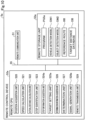
- the remote storage unit 53 stores various types of information, including various programs PG5 that control the operation of the remote control device 5, a vehicle detection model DM1, an object detection model DM2, a target distance database DB, and a reference route RR.
- the details of the vehicle detection model DM1, the object detection model DM2, the target distance database DB, and the reference route RR are described later.
- the remote storage unit 53 includes, for example, RAM, ROM, a hard disk drive (HDD) and the like.
- the remote CPU 52 functions as a position acquisition unit 520, a speed calculation unit 521, an actual distance calculation unit 522, a step identification unit 523, a step information acquisition unit 524, and a target setting unit 525 by expanding the various programs PG5 stored in the remote storage unit 53. Furthermore, the remote CPU 52 functions as a determination information acquisition unit 526, a determination unit 527, a signal generation unit 528, and a remote transmission unit 529 by expanding the various programs PG5 stored in the remote storage unit 53.
- the position acquisition unit 520 acquires vehicle position information using detection results output from the external sensors.
- the vehicle position information is position information that serves as the base in generating the running control signals.
- the vehicle position information includes the position and orientation of the vehicle 10 in the global coordinate system of the factory.
- the position acquisition unit 520 acquires the vehicle position information using external camera images acquired from the external cameras 9, which are external sensors.
- the position acquisition unit 520 detects the outer shape of the vehicle 10, for example, from the external camera image, calculates the coordinates of the external camera image, i.e., the coordinates of the positioning point of the vehicle 10 in the local coordinate system, and converts the calculated coordinates to the coordinates in the global coordinate system to acquire the position of the vehicle 10.
- the outer shape of the vehicle 10 in the captured image may be detected by inputting the external camera image to a detection model using artificial intelligence, for example.
- the detection model is prepared in the control system 1 or outside the control system 1.
- the detection model is stored in advance in a memory of the remote storage unit r 53, for example.
- An example of the detection model is a learned machine learning model that was learned so as to realize either semantic segmentation or instance segmentation.
- a convolution neural network (CNN) learned through supervised learning using a learning dataset is applicable as this machine learning model.
- the learning dataset contains a plurality of training images including the vehicle 10, and a label showing whether each region in the training image is a region indicating the vehicle 10 or a region indicating a subject other than the vehicle 10, for example.
- a parameter for the CNN is preferably updated through backpropagation in such a manner as to reduce error between output result obtained by the detection model and the label.
- the server 200 can acquire the orientation of the vehicle 10 through estimation based on the direction of a motion vector of the vehicle 10 detected from change in location of a feature point of the vehicle 10 between frames of the captured images using optical flow process, for example.
- the speed calculation unit 521 calculates the running speed of the vehicle 10.
- the speed calculation unit 521 calculates the running speed of the vehicle 10 using, for example, the output value of the wheel speed sensor 271 mounted on the vehicle 10. In this case, the speed calculation unit 521 calculates the running speed of the vehicle 10 based on the wheel speed per unit time after performing calculations such as averaging the wheel speed of each wheel.
- the method for calculating the running speed of the vehicle 10 is not limited to that described above. Further, at least some of the functions of the speed calculation unit 521 may be performed by the wheel speed sensor 271 or the vehicle CPU 22.
- the actual distance calculation unit 522 calculates the actual distance Da between the front vehicle 101 and the rear vehicle 102.
- the actual distance calculation unit 522 calculates the actual distance Da between the front vehicle 101 and the rear vehicle 102, for example, by a calculation process using the vehicle position information, the running speed of the vehicle 10, and the elapsed time after the acquisition of the vehicle position information, etc.
- the method for calculating the actual distance Da between the front vehicle 101 and the rear vehicle 102 is not limited to that described above.
- the actual distance calculation unit 522 may, for example, calculate the actual distance Da between the front vehicle 101 and the rear vehicle 102 using the detection results output from the internal sensors.
- the actual distance calculation unit 522 may calculate the actual distance Da between the front vehicle 101 and the rear vehicle 102 using the external camera images.
- the step identification unit 523 identifies one production step being performed on the vehicle 10 targeted for the remote control, from among a plurality of production steps in the production process of the vehicle 10.
- the step identification unit 523 identifies the production step being performed on the vehicle 10 targeted for the remote control by detecting, for example, feature points that allow identification of a plurality of production steps included in the on-vehicle camera image through image analysis. Specifically, for example, if there is an object (hereinafter referred to as a "feature object”) installed only at the work site where the one production step is performed, the step identification unit 523 detects the feature object included in the on-vehicle camera image as feature points. That is, in this case, the feature point is the shape of the feature object.
- the step identification unit 523 detects the color of the wall surface included in the on-vehicle camera image as feature points. Further, for example, if objects with labels, such as letters, symbols, figures, etc. for identifying a plurality of production steps are installed at a work site, the step identification unit 523 detects the labels included in the internal captured image as feature points.
- the method for identifying the one production step being performed on the vehicle 10 is not limited to that described above.
- the step identification unit 523 may identify the one production step being performed on the vehicle 10 by using the external camera image.
- the step information acquisition unit 524 acquires information (hereinafter referred to as production step information) regarding the one production step being performed on at least one of the front vehicle 101 and the rear vehicle 102. That is, the step information acquisition unit 524 acquires production step information with regard to the one production step identified by the step identification unit 523.
- the production step information is information in which production step identification information and work information are associated with each other.
- the production step identification information is a unique ID (identifier) assigned to each of the plurality of production steps included in the production process of the vehicle 10 to identify them one another, and there is no overlap of production step identification information among the production steps.
- the work information indicates the content of work of the production step identified by the production step identification information. In other words, the production step information indicates which of a plurality of production steps in the production process is to be performed, as well as the content of work to be performed. Therefore, the number of production step information is the same as the number of production steps in the production process.
- the work information includes inter-vehicle work information.
- the inter-vehicle work information indicates whether or not a work performed by allowing workers to enter the space between the front vehicle 101 and the rear vehicle 102 (this work will be hereinafter referred to as "inter-vehicle work") is performed.
- the inter-vehicle work is an assembly work to assemble, for example, parts such as lamps (not shown) and stickers (not shown) or on-vehicle devices such as batteries (not shown) to the rear side of the front vehicle 101 or to the front side of the rear vehicle 102.
- the target setting unit 525 sets a target distance Dg between the front vehicle 101 and the rear vehicle 102 according to the production process. Specifically, the target setting unit 525 sets the target distance Dg between the front vehicle 101 and the rear vehicle 102 according to the content of work indicated by the work information associated with the production step identification information indicating the one production step that is being performed on the front vehicle 101 or the rear vehicle 102. If the one production step is being performed, the target setting unit 525 sets the target distance Dg to a distance according to the content of the work of the one production step. Specifically, the target setting unit 525 sets the target distance Dg using, for example, the target distance database DB stored in advance in the remote storage unit 53 as well as the production step information acquired by the step information acquisition unit 524.
- the target distance database DB is a database in which the production step identification information and the target distance Dg according to the content of the work of the production step identified by the production step identification information are associated with each other.
- the target setting unit 525 sets the target distance Dg for the production step in which the inter-vehicle work is performed to be longer than the target distance Dg for the production step in which the inter-vehicle work is not performed, using the production step information.
- the target distance Dg in the production step in which the inter-vehicle work is performed is set, for example, according to the number of workers engaged in the inter-vehicle work and the range of the work region required for the inter-vehicle work.
- the target setting unit 525 performs the following process when the determination unit 527 determines that the one production step that is being performed on the vehicle 10 and that involves inter-vehicle work has been completed.
- the target setting unit 525 sets the target distance Dg between the front vehicle 101 and the rear vehicle 102 to a standard distance Ds.
- the standard distance Ds is a distance between the front vehicle 101 and the rear vehicle 102 and is shorter than the target distance Dg in the case where the inter-vehicle work is being performed.
- the standard distance Ds may be the same as the target distance Dg in any production step in which inter-vehicle work is not performed, from among the plurality of production steps in the production process.
- the target setting unit 525 sets the target distance Dg between the front vehicle 101 and the rear vehicle 102 to the standard distance Ds.
- the movement process is a process in which the vehicle 10 runs between a first work site and a second work site during the production process.
- the first work site is the place where the one production step, which is performed on the vehicle 10 and identified by the step identification unit 523, is performed.
- the second work site is the place where the production step subsequent to the one production step is performed (this subsequent production step will be hereinafter referred to as a next production step).
- the case where the specific conditions are satisfied is, for example, a case where the first case and the second case are satisfied.
- the first case is a case where there is a movement process in which the vehicle 10 runs on the track R that connects the first work site and the second work site, because, for example, the first work site and the second work site are located in different buildings.
- the second case is a case where the one production step performed at the first work site is a production step in which inter-vehicle work is performed.
- the method for setting the target distance Dg and the content thereof are not limited to those described above.
- the target setting unit 525 may set the target distance Dg, for example, using on-vehicle sensor information or external camera images acquired by the first type sensor group 26 mounted on the vehicle 10.
- the determination information acquisition unit 526 acquires information (hereinafter referred to as determination information) for determining whether or not the one production step identified by the step identification unit 523 has been completed.
- the determination information includes information such as on-vehicle camera images and external camera images acquired after the time point when the control to set the actual distance Da between the front vehicle 101 and the rear vehicle 102 to a distance according to the content of the work of the one production step was started.
- the types of information included in the determination information and the acquisition timing are not limited to those described above.
- the determination information may include, for example, on-vehicle sensor information other than on-vehicle camera images or vehicle position information.
- the determination unit 527 determines whether or not the one production step being performed on the vehicle 10 has been completed using the determination information. In other words, the determination unit 527 determines whether or not the production step identified by the step identification unit 523 has been completed. The determination unit 527 determines whether or not the one production step being performed on the vehicle 10 has been completed by detecting, for example, a worker captured in the on-vehicle camera image or external camera image as the determination information by image analysis using the object detection model DM2.
- the object detection model DM2 is a trained machine learning model used to detect objects, such as workers, that have entered the surrounding area of the vehicle 10. For example, a CNN is used as the object detection model DM2.
- the determination unit 527 determines that the one production step has not been completed, for example, when a worker is detected in the surrounding area of the front vehicle 101 and the rear vehicle 102 in the on-vehicle camera image or the external camera image.
- the determination unit 527 determines that the one production step has been completed, for example, when no worker is detected in the surrounding area of the front vehicle 101 and the rear vehicle 102 in the on-vehicle camera image or the external camera image.
- the method for determining whether or not the one production step being performed on the vehicle 10 has been completed is not limited to that described above.
- the signal generation unit 528 generates running control signals. Specifically, the signal generation unit 528 determines the target location to which the vehicle 10 is supposed to go next. In the present embodiment, the target location is expressed by X, Y, and Z coordinates in the global coordinate system.
- the remote storage unit 53 of the remote control device 5 contains a reference route RR stored in advance as a route along which the vehicle 10 is to run. The route is expressed by a node indicating a departure place, a node indicating a way point, a node indicating a destination, and a link connecting nodes to each other.
- the signal generation unit 528 determines the target location to which the vehicle 10 is to move next using the vehicle location information and the reference route RR.
- the signal generation unit 528 determines the target location on the reference route RR ahead of a current location of the vehicle 10.
- the signal generation unit 528 generates a running control signal for causing the vehicle 10 to run toward the determined target location.
- the signal generation unit 528 calculates a running speed of the vehicle 10 from transition of the location of the vehicle 10 and makes comparison between the calculated running speed and a target speed of the vehicle 10.
- the target speed is determined, for example, according to the actual distance Da between the front vehicle 101 and the rear vehicle 102 and the target distance Dg between the front vehicle 101 and the rear vehicle 102. If the running speed is lower than the target speed, the signal generation unit 528 generally determines an acceleration in such a manner as to accelerate the vehicle 10. If the running speed is higher than the target speed as, the signal generation unit 528 generally determines an acceleration in such a manner as to decelerate the vehicle 10.
- server 200 determines a steering angle and an acceleration in such a manner as to prevent the vehicle 10 from deviating from the reference route RR. If the vehicle 10 is not on the reference route RR, in other words, if the vehicle 10 deviates from the reference route, the signal generation unit 528 determines a steering angle and an acceleration in such a manner as to return the vehicle 10 to the reference route RR.
- the signal generation unit 528 generates the following running control signals using the reference route RR, the actual distance Da between the front vehicle 101 and the rear vehicle 102 and the target distance Dg, the running speeds of the front vehicle 101 and the rear vehicle 102, the target speed, the vehicle position information, and the like.
- the signal generation unit 528 generates a running control signal (hereinafter referred to as a first control signal) to set the actual distance Da between the front vehicle 101 and the rear vehicle 102 to the target distance Dg according to the production step information.
- the signal generation unit 528 generates a first control signal, which is at least one of a front first control signal and a rear first control signal.
- the front first control signal is the first control signal that defines the running operation of the front vehicle 101 in order to set the actual distance Da between the front vehicle 101 and the rear vehicle 102 to the target distance Dg according to the production step information. For example, if the target distance Dg is longer than the actual distance Da between the front vehicle 101 and the rear vehicle 102, the signal generation unit 528 generates a front first control signal to cause the front vehicle 101 to perform an acceleration process to increase acceleration in the forward direction.
- the rear first control signal is the first control signal that defines the running operation of the rear vehicle 102 in order to set the actual distance Da between the front vehicle 101 and the rear vehicle 102 to the target distance Dg according to the production step information. For example, if the target distance Dg is longer than the actual distance Da between the front vehicle 101 and the rear vehicle 102, the signal generation unit 528 generates the following rear first control signal. In this case, the signal generation unit 528 generates a rear first control signal to cause the rear vehicle 102 to perform at least one of a deceleration process to decrease the acceleration in the forward direction and a backing process to move the rear vehicle 102 backward in the opposite direction of the forward direction.
- the signal generation unit 528 may generate the following rear first control signal. In this case, the signal generation unit 528 may generate the rear first control signal to cause the rear vehicle 102 to perform a stopping process to stop the running operation.
- the first control signal includes, in addition to the acceleration of the vehicle 10, the steering angle as a parameter. This allows correction of positional deviation from the reference route RR in the process of changing the actual distance Da between the front vehicle 101 and the rear vehicle 102 to the target distance Dg.
- the signal generation unit 528 may further include a parameter that defines the duration of the running operation defined by the first control signal. In this way, the duration of running at the acceleration indicated by the first control signal can be specified. This allows to keep the actual distance Da between the front vehicle 101 and the rear vehicle 102 in a state of being close to the target distance Dg. Further, in this case, if the first control signal includes the steering angle as a parameter, the duration of running at the steering angle indicated by the first control signal can be specified. This allows to keep the relative position of the vehicle 10 in a state of being close to the reference route RR.
- the signal generation unit 528 may further include a parameter that defines the duration of the running operation defined by the first control signal. In this way, after the first control signal switches the traveling direction of the vehicle 10 from the forward direction to the backward direction, which is the opposite of the forward direction, the time required to return the traveling direction of the vehicle 10 from the backward direction to the forward direction can be specified. This allows to keep the actual distance Da between the front vehicle 101 and the rear vehicle 102 in a state of being close to the target distance Dg.
- the signal generation unit 528 may further include a parameter that defines the duration of the running operation defined by the first control signal. In this way, the time the vehicle 10 is stopped by the first control signal can be specified. This allows to keep the actual distance Da between the front vehicle 101 and the rear vehicle 102 in a state of being close to the target distance Dg.
- the signal generation unit 528 performs the following process when the determination unit 527 determines that the one production step that is being performed on the vehicle 10 and that involves inter-vehicle work has been completed.
- the signal generation unit 528 generates a running control signal (hereinafter referred to as a second control signal) to set the actual distance Da between the front vehicle 101 and the rear vehicle 102 to the standard distance Ds as the target distance Dg in the movement process.
- the signal generation unit 528 generates a second control signal, which is at least one of a front second control signal and a rear second control signal.
- the front second control signal is a second control signal to define the running operation of the front vehicle 101 in order to set the actual distance Da between the front vehicle 101 and the rear vehicle 102 to the standard distance Ds in the movement process. For example, if the standard distance Ds is shorter than the actual distance Da between the front vehicle 101 and the rear vehicle 102, the signal generation unit 528 generates the following front second control signal. In this case, the signal generation unit 528 generates a front second control signal to cause the front vehicle 101 to perform at least one of the deceleration process and the backing process. Further, if the standard distance Ds is shorter than the actual distance Da between the front vehicle 101 and the rear vehicle 102, the signal generation unit 528 may generate the front second control signal to cause the front vehicle 101 to perform the stopping process.
- the rear second control signal is a second control signal to define the running operation of the rear vehicle 102 in order to set the actual distance Da between the front vehicle 101 and the rear vehicle 102 to the standard distance Ds in the movement process. For example, if the standard distance Ds is shorter than the actual distance Da between the front vehicle 101 and the rear vehicle 102, the signal generation unit 528 generates the rear second control signal to cause the rear vehicle 102 to perform the acceleration process.
- the second control signal includes, in addition to the acceleration of the vehicle 10, the steering angle as a parameter. This allows correction of positional deviation from the reference route RR in the process of changing the actual distance Da between the front vehicle 101 and the rear vehicle 102 to the standard distance Ds.
- the signal generation unit 528 may further include a parameter that defines the duration of the running operation defined by the second control signal. In this way, the duration of running at the acceleration indicated by the second control signal can be specified. This allows to keep the actual distance Da between the front vehicle 101 and the rear vehicle 102 in a state of being close to the standard distance Ds. Further, in this case, if the second control signal includes the steering angle as a parameter, the duration of running at the steering angle indicated by the second control signal can be specified. This allows to keep the relative position of the vehicle 10 in a state of being close to the reference route RR.
- the signal generation unit 528 may further include a parameter that defines the duration of the running operation defined by the second control signal. In this way, after the second control signal switches the traveling direction of the vehicle 10 from the forward direction to the backward direction, which is the opposite of the forward direction, the time required to return the traveling direction of the vehicle 10 from the backward direction to the forward direction can be specified. This allows to keep the actual distance Da between the front vehicle 101 and the rear vehicle 102 in a state of being close to the standard distance Ds.
- the signal generation unit 528 may further include a parameter that defines the duration of the running operation defined by the second control signal. In this way, the time the vehicle 10 is stopped by the second control signal can be specified. This allows to keep the actual distance Da between the front vehicle 101 and the rear vehicle 102 in a state of being close to the standard distance Ds.
- the remote transmission unit 529 transmits the running control signal generated by the signal generation unit 528 to the vehicle 10 for which the running operation is to be controlled.
- the remote transmission unit 529 may transmit the running control signal to the vehicle 10 via an external device such as the external camera 9 or the like.
- the remote transmission unit 529 transmits the running control signal to the external camera 9.
- the external camera 9 then transmits the running control signal received from the remote control device 5 to the vehicle 10. This allows the vehicle 10 to receive the running control signal from the external camera 9 that is closer to the vehicle 10. This makes the transmission less susceptible to communication failures. Therefore, it is possible to reduce the likelihood that the vehicle 10 may stop due to a communication failure during the period of unmanned driving control.
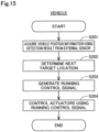
- the remote CPU 52 repeats the acquisition of the vehicle position information, the determination of the target location, the generation of the running control signal, the transmission of the running control signal, and the like, in a predetermined cycle. At least some of the functions of the remote CPU 52 may be implemented as a function of the vehicle control device 2 or the external camera 9.
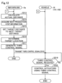
- Fig. 4 is a flowchart of procedures in the process of running control of the vehicle 10 in the first embodiment. The flow shown in Fig. 4 is repeated, for example, every predetermined time from the time point at which the running of the vehicle 10 by unmanned driving is started.
- the position acquisition unit 520 of the remote control device 5 acquires the vehicle position information using the detection result output from the external camera 9 as an external sensor.
- the signal generation unit 528 of the remote control device 5 determines the target location to which the vehicle 10 should go next.
- the signal generation unit 528 of the remote control device 5 generates a running control signal to cause the vehicle 10 to run toward the determined target location.
- the remote transmission unit 529 of the remote control device 5 transmits the generated running control signal to the vehicle 10.
- the vehicle control device 2 mounted on the vehicle 10 receives the running control signal transmitted from the remote control device 5.
- the operation control unit 223 of the vehicle control device 2 controls the actuator group 29 using the received running control signal, thereby causing the vehicle 10 to run at the acceleration and the steering angle indicated by the running control signal.
- the vehicle control device 2 repeats the reception of the running control signal and the control of the actuator group 29 in a predetermined cycle.
- the control system 1 of the present embodiment enables the vehicle 10 to run by remote control, thereby moving the vehicle 10 without using transport equipment, such as a crane, a conveyor, or the like.
- the following describes an exemplary case in which, after the one production step that performs inter-vehicle work on the vehicle 10 is performed at the first work site, the next production step is performed at the second work site, and the vehicle 10 runs on the track R that connects the first work site and the second work site. That is, the following describes a control method in the case where the production process has a movement process and the one production step is performed on the vehicle 10.
- Fig. 5 is a first flowchart showing a first adjustment method.
- Fig. 6 is a second flowchart showing the first adjustment method.
- the first adjustment method is a method to adjust the actual distance Da between the front vehicle 101 and the rear vehicle 102 to the target distance Dg according to the content of the work of the one production step being performed on the vehicle 10.
- the remote transmission unit 529 of the remote control device 5 performs the following process.
- the remote transmission unit 529 transmits a first request signal to the external camera 9, the front vehicle 101, and the rear vehicle 102 (step S302).
- the external camera 9 acquires the external camera image (step S304). After the step S304, the external camera 9 transmits the external camera image to the remote control device 5, together with the camera identification information (step S305).
- step S306 If the state acquisition unit 221 of the vehicle 10 receives the first request signal (step S306: Yes), the state acquisition unit 221 acquires the on-vehicle sensor information acquired by the first type sensor group 26 and the second type sensor group 27 (step S307). After the step S307, the vehicle transmission unit 222 transmits the on-vehicle sensor information to the remote control device 5, together with the vehicle identification information (step S308). Any of the steps from the step S303 to the step S305 and the step S306 to the step S308 may be executed first, or they may be executed concurrently.
- the position acquisition unit 520 of the remote control device 5 acquires the vehicle position information (step S309).
- the speed calculation unit 521 calculates the respective running speeds of the front vehicle 101 and the rear vehicle 102 (step S310).
- the actual distance calculation unit 522 performs the following process using at least some of the vehicle position information and the running speed of the front vehicle 101 and the vehicle position information and the running speed of the rear vehicle 102. In this case, the actual distance calculation unit 522 calculates the actual distance Da between the front vehicle 101 and the rear vehicle 102 (step S311).
- the step identification unit 523 identifies the one production step being performed on the front vehicle 101 and the rear vehicle 102 using the on-vehicle camera image and the like (step S312).
- the step information acquisition unit 524 acquires the production step information with regard to the one production step identified by the step identification unit 523 (step S313).
- the target setting unit 525 sets the target distance Dg to a distance according to the content of the work of the one production step using the target distance database DB, the production step information, and the like (step S314).
- the signal generation unit 528 determines the target location using the reference route RR, the actual distance Da between the front vehicle 101 and the rear vehicle 102 and the target distance Dg, the running speeds of the front vehicle 101 and the rear vehicle 102, the target speed, the vehicle position information, and the like (step S315).
- the signal generation unit 528 generates at least one of the front first control signal and the rear first control signal to enable the vehicle 10 to run toward the determined target location (step S316).
- the remote transmission unit 529 transmits the first control signal to the vehicle 10 for which the running operation is to be controlled (step S317). That is, the remote transmission unit 529 transmits the front first control signal to the front vehicle 101 and transmits the rear first control signal to the rear vehicle 102.
- step S318 If the vehicle control device 2 mounted on the vehicle 10 receives the first control signal (step S318: Yes), the operation control unit 223 controls the actuator group 29 using the received first control signal, thereby causing the vehicle 10 to run at the acceleration and the steering angle indicated by the first control signal (step S319).
- Fig. 7 is a first flowchart showing a second adjustment method.
- Fig. 8 is a second flowchart showing the second adjustment method.
- the second adjustment method is a method to adjust the actual distance Da between the front vehicle 101 and the rear vehicle 102 to the standard distance Ds in the movement process. That is, the second adjustment method is performed after the step S319 of the first adjustment method shown in Fig. 6 .
- the remote transmission unit 529 of the remote control device 5 performs the following process.
- the determination timing is a timing after the timing when the step S319 of the first adjustment method shown in Fig. 6 is performed.
- the determination timing is, for example, the timing when the elapsed time after the timing of the start of running according to the first control signal becomes equal to or more than a predetermined time, or when a predetermined time has passed after the previous determination timing.
- the remote transmission unit 529 transmits a second request signal to the external camera 9, the front vehicle 101, and the rear vehicle 102 (step S402).
- the external camera 9 receives the second request signal (step S403: Yes)
- the external camera 9 acquires the external camera image (step S404).
- the external camera 9 transmits the external camera image to the remote control device 5, together with the camera identification information (step S405).
- step S406 If the vehicle control device 2 mounted on the vehicle 10 receives the second request signal (step S406: Yes), the state acquisition unit 221 acquires the on-vehicle sensor information (step S407). After the step S407, the vehicle transmission unit 222 transmits the on-vehicle sensor information to the remote control device 5, together with the vehicle identification information (step S408). Any of the steps from the step S403 to the step S405 and the step S406 to the step S408 may be executed first, or they may be executed concurrently.
- step S409 Yes
- the determination unit 527 determines whether or not the one production step identified by the step identification unit 523 has been completed using the determination information (step S410). That is, the determination unit 527 determines whether or not the one production step as the target for the control by the first control signal has been completed. If it is determined by the determination unit 527 that the one production step identified by the step identification unit 523 has been completed (step S410: Yes), the position acquisition unit 520 acquires the vehicle position information (step S411). After the step S411, the speed calculation unit 521 calculates the respective running speeds of the front vehicle 101 and the rear vehicle 102 (step S412). In contrast, if it is determined by the determination unit 527 that the production step identified by the step identification unit 523 has not been completed (step S410: No), the process returns to the step S401 and each step from the step S401 to the step S410 is repeatedly performed.
- the actual distance calculation unit 522 performs the following process using at least some of the vehicle position information and the running speed of the front vehicle 101 and the vehicle position information and the running speed of the rear vehicle 102. In this case, the actual distance calculation unit 522 calculates the actual distance Da between the front vehicle 101 and the rear vehicle 102 (step S413).
- the target setting unit 525 sets the target distance Dg between the front vehicle 101 and the rear vehicle 102 to the standard distance Ds (step S414).
- the signal generation unit 528 determines the target location using the reference route RR, the actual distance Da between the front vehicle 101 and the rear vehicle 102 and the standard distance Ds, the running speeds of the front vehicle 101 and the rear vehicle 102, the target speed, the vehicle position information, and the like (step S415).
- the signal generation unit 528 generates at least one of the front second control signal and the rear second control signal to enable the vehicle 10 to run toward the determined target location (step S416).
- the remote transmission unit 529 transmits the second control signal to the vehicle 10 for which the running operation is to be controlled (step S417). That is, the remote transmission unit 529 transmits the front second control signal to the front vehicle 101 and transmits the rear second control signal to the rear vehicle 102.
- step S418 If the vehicle control device 2 mounted on the vehicle 10 receives the second control signal (step S418: Yes), the operation control unit 223 controls the actuator group 29 using the received second control signal, thereby causing the vehicle 10 to run at the acceleration and the steering angle indicated by the second control signal (step S419).
- the remote control device 5 is capable of setting the target distance Dg between the front vehicle 101 and the rear vehicle 102 according to the production step information regarding the one production step. Then, the remote control device 5 can adjust the actual distance Da between the front vehicle 101 and the rear vehicle 102 so that the actual distance Da between the front vehicle 101 and the rear vehicle 102 is equal to the target distance Dg, which is set according to the production step information regarding the one production step being performed on the vehicle 10. That is, the remote control device 5 can set the actual distance Da between the front vehicle 101 and the rear vehicle 102, which are running under remote control, to an inter-vehicle distance appropriate for the content of the work of the one production step being performed in the production process.
- the work information included in the production step information includes inter-vehicle work information.
- other work than the inter-vehicle work e.g., work on the side surface of the vehicle 10.
- the remote control device 5 when the target distance Dg is longer than the actual distance Da between the front vehicle 101 and the rear vehicle 102, the remote control device 5 is capable of generating the rear first control signal to cause the rear vehicle 102 to perform at least one of the deceleration process and the backing process. In this way, the actual distance Da between the front vehicle 101 and the rear vehicle 102 can be easily increased by controlling at least one of the acceleration and the traveling direction of the rear vehicle 102.
- the remote control device 5 when the target distance Dg is longer than the actual distance Da between the front vehicle 101 and the rear vehicle 102, the remote control device 5 is capable of generating the front first control signal to cause the front vehicle 101 to perform the acceleration process.
- the actual distance Da between the front vehicle 101 and the rear vehicle 102 can be easily increased by controlling the acceleration of the front vehicle 101.
- the actual distance Da between the front vehicle 101 and the rear vehicle 102 can be easily increased by providing a difference in running speed between the front vehicle 101 and the rear vehicle 102.
- the remote control device 5 is capable of generating and transmitting both the front first control signal and the rear first control signal so as to set the actual distance Da between the front vehicle 101 and the rear vehicle 102 to the target distance Dg.
- This allows the vehicle control devices 2 of the front vehicle 101 and the rear vehicle 102 that have received the first control signal to respectively control the operation using the first control signal, thereby adjusting the actual distance Da between the front vehicle 101 and the rear vehicle 102 to the target distance Dg.
- This for example, reduces the time required for setting the actual distance Da between the front vehicle 101 and the rear vehicle 102 to the target distance Dg, thereby efficiently changing the actual distance Da between the front vehicle 101 and the rear vehicle 102.
- the remote control device 5 is capable of determining whether or not the one production step being performed on the vehicle 10 has been completed using the determination information. Then, when the remote control device 5 determines that the one production step in which the inter-vehicle work is performed has been completed, the remote control device 5 can adjust the actual distance Da between the front vehicle 101 and the rear vehicle 102 to the standard distance Ds in the movement process. In other words, according to the first embodiment described above, the remote control device 5 is capable of changing the actual distance Da between the front vehicle 101 and the rear vehicle 102 to the standard distance Ds in the movement process after the one production step is completed. This prevents prolonging the actual distance Da between the front vehicle 101 and the rear vehicle 102 more than necessary during the movement process after the production step in which the inter-vehicle work is performed is completed. This allows the vehicle 10 to efficiently move during the movement process.
- the control system 1 is capable of causing the vehicle 10 to run by unmanned driving in a factory where a plurality of production steps are performed. That is, the control system 1 enables the vehicle 10 to be transported in the factory without using belt conveyers.
- a belt conveyer is used to transport the vehicle 10
- the actual distance Da between the front vehicle 101 and the rear vehicle 102 is likely to be set as follows.
- the actual distance Da between the front vehicle 101 and the rear vehicle 102 is likely to be set to the inter-vehicle distance according to the content of the work of the production step that requires the longest inter-vehicle distance, from among the plurality of production steps that are performed on the vehicles 10 placed on the same belt.
- the actual distance Da between the front vehicle 101 and the rear vehicle 102 may become unnecessarily longer than the inter-vehicle distance appropriate for the content of the work of the production step.
- control system 1 is capable of controlling the running operation of the vehicle 10 without using a belt conveyer, thereby transporting the vehicle 10 in a factory, and also adjusting the actual distance Da between the front vehicle 101 and the rear vehicle 102. This makes it possible to optimize the inter-vehicle distance between the plurality of vehicles 10 during the production process.
- Fig. 9 shows a schematic structure of a control system 1a in the second embodiment.
- the present embodiment differs from the first embodiment in the control during the movement process. Accordingly, the production process has a movement process in which the vehicle 10 runs between the first work site where the one production step is performed and the second work site where the next production step, which is performed after the one production step, is performed.
- a third adjustment method is performed after the first adjustment method shown in Figs. 5 and 6 . That is, in the present embodiment, the third adjustment method is performed instead of the second adjustment method shown in Figs. 7 and 8 .
- the third adjustment method is a method to adjust the actual distance Da between the front vehicle 101 and the rear vehicle 102 to a next target distance Dn shown in Fig. 9 .
- the next target distance Dn is the distance between the front vehicle 101 and the rear vehicle 102 according to the next production step information, which is information regarding the next production step. That is, the next target distance Dn is the distance between the front vehicle 101 and the rear vehicle 102 appropriate for the content of the work of the next production step.
- the rest of the structure of the control system 1a is the same as that of the first embodiment, unless otherwise specified.
- the same structure as that of the first embodiment is described with the same reference symbols and the explanation thereof is omitted.
- Fig. 10 shows a schematic structure of a remote control device 5a in the second embodiment.
- the remote control device 5a includes a remote communication unit 51, a remote CPU 52a, and a remote storage unit 53a.
- the remote CPU 52a functions as a position acquisition unit 520, a speed calculation unit 521, an actual distance calculation unit 522, a step identification unit 523, a step information acquisition unit 524a, and a target setting unit 525a by expanding various programs PG5a stored in the remote storage unit 53a.
- the remote CPU 52a functions as a determination information acquisition unit 526, a determination unit 527, a signal generation unit 528a, and a remote transmission unit 529 by expanding the various programs PG5a stored in the remote storage unit 53a.
- the step information acquisition unit 524a further acquires the next production step information.
- the target setting unit 525a sets the target distance Dg between the front vehicle 101 and the rear vehicle 102 to the next target distance Dn.
- the signal generation unit 528a performs the following process when the determination unit 527 determines that the one production step identified by the step identification unit 523 has been completed. In this case, the signal generation unit 528a generates a running control signal (hereinafter referred to as a third control signal) to set the actual distance Da between the front vehicle 101 and the rear vehicle 102 to the next target distance Dn in the movement process.
- a running control signal hereinafter referred to as a third control signal
- the signal generation unit 528 generates at least one of a front third control signal and a rear third control signal.
- the front third control signal is the third control signal that defines the running operation of the front vehicle 101 in order to set the actual distance Da between the front vehicle 101 and the rear vehicle 102 to the next target distance Dn.
- the rear third control signal is the third control signal that defines the running operation of the rear vehicle 102 in order to set the actual distance Da between the front vehicle 101 and the rear vehicle 102 to the next target distance Dn.
- Fig. 11 is a first flowchart showing the third adjustment method.
- Fig. 12 is a second flowchart showing the third adjustment method. As mentioned above, the third adjustment method is performed after the step S319 of the first adjustment method shown in Fig. 6 .
- step S501 when the determination timing comes (step S501: Yes), the remote transmission unit 529 of the remote control device 5 transmits a third request signal to the external camera 9, the front vehicle 101, and the rear vehicle 102 (step S502).
- the external camera 9 acquires the third request signal (step S503: Yes)
- the external camera 9 acquires the external camera image (step S504).
- the external camera 9 transmits the external camera image to the remote control device 5, together with the camera identification information (step S505).
- step S506 If the vehicle control device 2 mounted on the vehicle 10 receives the third request signal (step S506: Yes), the state acquisition unit 221 acquires the on-vehicle sensor information (step S507). After the step S507, the vehicle transmission unit 222 transmits the on-vehicle sensor information to the remote control device 5, together with the vehicle identification information (step S508). Any of the steps from the step S503 to the step S505 and the step S506 to the step S508 may be executed first, or they may be executed concurrently.
- the determination unit 527 determines whether or not the one production step identified by the step identification unit 523 has been completed using the determination information (step S510). If it is determined by the determination unit 527 that the one production step identified by the step identification unit 523 has been completed (step S510: Yes), the position acquisition unit 520 acquires the vehicle position information (step S511). After the step S511, the speed calculation unit 521 calculates the respective running speeds of the front vehicle 101 and the rear vehicle 102 (step S512). In contrast, if it is determined by the determination unit 527 that the one production step identified by the step identification unit 523 has not been completed (step S510: No), the process returns to the step S501 and each step from the step S501 to the step S510 is repeatedly performed.
- the actual distance calculation unit 522 calculates the actual distance Da between the front vehicle 101 and the rear vehicle 102 (step S513).
- the step information acquisition unit 524a acquires the next production step information (step S514).
- the target setting unit 525a sets the target distance Dg between the front vehicle 101 and the rear vehicle 102 to the next target distance Dn (step S515).
- the signal generation unit 528a determines the target location using the reference route RR, the actual distance Da between the front vehicle 101 and the rear vehicle 102 and the next target distance Dn, the running speeds of the front vehicle 101 and the rear vehicle 102, the target speed, the vehicle position information, and the like (step S516). After the step S516, the signal generation unit 528a generates at least one of the front third control signal and the rear third control signal to enable the vehicle 10 to run toward the determined target location (step S517). After the step S517, the remote transmission unit 529 transmits the third control signal to the vehicle 10 for which the running operation is to be controlled in the movement process (step S518).
- step S519 If the vehicle control device 2 mounted on the vehicle 10 receives the third control signal (step S519: Yes), the operation control unit 223 controls the actuator group 29 using the received third control signal, thereby causing the vehicle 10 to run at the acceleration, etc. indicated by the third control signal (step S520).
- the actual distance Da between the front vehicle 101 and the rear vehicle 102 can be adjusted to the next target distance Dn in the movement process. That is, after the one production step is completed, the actual distance Da between the front vehicle 101 and the rear vehicle 102 can be adjusted in advance, i.e., before the next production step begins, to an inter-vehicle distance appropriate for the content of the work of the next production step. This makes it possible to optimize the actual distance Da between the front vehicle 101 and the rear vehicle 102 while the vehicle 10 is running on the track R between the work sites where the one production step and the next production step are performed.
- the actual distance Da between the front vehicle 101 and the rear vehicle 102 is the inter-vehicle distance according to the content of the work of the next production step. This improves the work efficiency and the safety of the workers in the next production step.
- Fig. 13 shows a schematic structure of a control system 1v in the third embodiment.
- the present embodiment differs from the first embodiment in that the control system 1v does not include the remote control device 5.
- a vehicle 10v in the present embodiment is capable of running by autonomous control of the vehicle 10v.
- the rest of the structure of the control system 1v is the same as that of the first embodiment, unless otherwise specified.
- the same structure as that of the first embodiment is described with the same reference symbols and the explanation thereof is omitted.
- Fig. 14 shows a schematic structure of a vehicle control device 2v in the third embodiment.
- Fig. 14 shows a part that represents the structure of the vehicle 10v.
- the vehicle control device 2v includes a vehicle storage unit 23v as the storage unit of the vehicle control device 2v, a vehicle CPU 22v as the central processing unit of the vehicle control device 2v, and an input/output interface 24.
- the vehicle storage unit 23v stores various types of information, including various programs PG2v that control the running operation of the vehicle 10v, a vehicle detection model DM1, an object detection model DM2, a target distance database DB, and a reference route RR.
- the vehicle storage unit 23 includes, for example, RAM, ROM, a hard disk drive (HDD) and the like.
- the vehicle CPU 22v functions as a position acquisition unit 211, a speed calculation unit 212, an actual distance calculation unit 213, and a step identification unit 214 by expanding the various programs PG2v stored in the vehicle storage unit 23v. Furthermore, the vehicle CPU 22v functions as a step information acquisition unit 215, a target setting unit 216, a signal generation unit 217, the state acquisition unit 221, and an operation control unit 223v by expanding the various programs PG2v stored in the vehicle storage unit 23v.
- the position acquisition unit 211 acquires vehicle position information using detection results output from the external sensors. In the present embodiment, the position acquisition unit 211 acquires the vehicle position information using detection results output from the external camera 9, which is an external sensor.
- the speed calculation unit 212 calculates the running speed of the vehicle 10v, which is the own vehicle.
- the speed calculation unit 521 may acquire the running speed of another vehicle 10v from the another vehicle 10v.
- the another vehicle 10v is a vehicle different from the own vehicle 10v and runs at least one of the front and rear of the own vehicle 10v.
- the actual distance calculation unit 213 calculates the actual distance Da between the own vehicle 10v and the another vehicle 10v.
- the step identification unit 214 identifies, from among a plurality of production steps in the production process, one production step that is being performed on the vehicle 10v, which is at least one of the own vehicle 10v and the another vehicle 10v.
- the step information acquisition unit 215 acquires the production step information regarding the one production step being performed on the vehicle 10v, which is at least one of the own vehicle 10v and the another vehicle 10v.
- the target setting unit 216 sets the target distance Dg between the own vehicle 10v and the another vehicle 10v according to the production process.
- the signal generation unit 217 generates various running control signals to set the actual distance Da between the own vehicle 10v and the another vehicle 10v to the target distance Dg.
- the signal generation unit 217 first determines the target location to which the own vehicle 10v is supposed to go next. Then, the signal generation unit 217 generates a running control signal to cause the own vehicle 10v to run toward the determined target location.
- the operation control unit 223v controls the actuator group 29 using the generated running control signal, thereby causing the own vehicle 10v to run according to the parameters indicated by the running control signal.
- the vehicle control device 2v repeats the acquisition of the vehicle position information, the determination of the target location, the generation of the running control signal, and the control of the actuators, in a predetermined cycle.
- Fig. 15 is a flowchart of procedures in the process of running control of the vehicle 10v in the third embodiment. The flow shown in Fig. 15 is repeated, for example, every predetermined time from the time point at which the running of the vehicle 10v by unmanned driving is started.
- the position acquisition unit 211 of the vehicle control device 2v acquires the vehicle position information using the detection result output from the external camera 9.
- the signal generation unit 217 determines the target location to which the vehicle 10v should go next.
- the signal generation unit 217 generates a running control signal to cause the vehicle 10v to run toward the determined target location.
- the operation control unit 223v controls the actuator group 29 using the generated running control signal, thereby causing the vehicle 10v to run according to the parameters indicated by the running control signal.
- control system 1v is capable of causing the vehicle 10v to run by autonomous control of the vehicle 10v without remote control of the vehicle 10v by the remote control device 5.
- the vehicle control device 2v is capable of setting the target distance Dg between the own vehicle 10v and the another vehicle 10v according to the production step information regarding the one production step. This enables adjustment of the actual distance Da between the own vehicle 10v and the another vehicle 10v so that the actual distance Da between the own vehicle 10v and the another vehicle 10v becomes the target distance Dg according to the production step information. This enables adjustment of the actual distance Da between the own vehicle 10v and the another vehicle 10v to an inter-vehicle distance appropriate for the content of the work of the one production step. Therefore, it is possible to prevent the actual distance Da between the own vehicle 10v and the another vehicle 10v from being unnecessarily longer than the target distance Dg.
- the vehicle control device 2v may set the target distance Dg so that the target distance Dg in a production step in which the inter-vehicle work is performed is longer than the target distance Dg in a production step in which the inter-vehicle work is not performed. In this way, it is possible to more reliably ensure a work area in which workers enter to engage in the work between the own vehicle 10v and the another vehicle 10v. This reduces the possibility of interference during the inter-vehicle work and also ensures safety when workers are engaged in the inter-vehicle work.
- the vehicle control device 2v may generate the following first control signal.
- the vehicle control device 2v may generate a first control signal to cause the own vehicle 10v to perform at least one of the deceleration process and the backing process. In this way, the actual distance Da between the own vehicle 10v and the another vehicle 10v can be increased by controlling one of the acceleration and the traveling direction of the own vehicle 10v.
- the vehicle control device 2v may generate the following first control signal.
- the vehicle control device 2v may generate a first control signal to cause the own vehicle 10v to perform the acceleration process. In this way, the actual distance Da between the own vehicle 10v and the another vehicle 10v can be increased by controlling the acceleration of the own vehicle 10v.
- the vehicle control device 2v may further include the determination information acquisition unit 526 and the determination unit 527. Then, when it is determined that the one production step in which inter-vehicle work is performed has been completed, the vehicle control device 2v may generate the following second control signal. In this case, the vehicle control device 2v may generate a second control signal to define the operation of the own vehicle 10v to set the actual distance Da between the own vehicle 10v and the another vehicle 10v to the standard distance Ds as the target distance Dg in the movement process. In this way, the vehicle control device 2v can determine whether or not the one production step that is being performed on at least one of the own vehicle 10v and the another vehicle 10v, and that involves inter-vehicle work has been completed.
- the vehicle control device 2v can set the target distance Dg between the own vehicle 10v and the another vehicle 10v to the next target distance Dn according to the next production step information. This allows the vehicle control device 2v to adjust the actual distance Da between the own vehicle 10v and the another vehicle 10v to the next target distance On in the movement process when it is determined that the one production step has been completed. This enables adjustment of the actual distance Da between the own vehicle 10v and the another vehicle 10v to an inter-vehicle distance appropriate for the content of the work of the next production step in advance before the start of the next production step.
- the determination information may include communicability information.
- the communicability information indicates whether or not the communicable device is capable of communication with the outside of the vehicle 10, 10v.
- the control system 1, 1a, 1v determines that the one production step in which inter-vehicle work is performed has been completed.
- the control system 1, 1a, 1v determines that the one production step in which inter-vehicle work is performed has not been completed.
- the control system 1, 1a, 1v can determine whether or not the one production step has been completed by using the availability of communication between the communicable device and the outside of the vehicle 10, 10v.
- control system 1, 1a, 1v may generate a second control signal to adjust the actual distance Da between the front vehicle 101 and the rear vehicle 102 to the standard distance Ds during the movement process in which the vehicle 10, 10v runs from the work site where the final production step was performed to the storage place after the all production steps are completed.
- the storage place is, for example, a yard.
- the production step information includes final step information that indicates whether or not the production step identified by the production step identification information is the final production step from among a plurality of production steps in the production process.
- the control system 1, 1a, 1v determines whether or not the one production step has been completed and whether or not the one production step is the final production step from among the plurality of production steps in the production process by using the production step information and the determination information. Then, when it is determined that the final production step of the production process has been completed, the control system 1, 1a, 1v generates the second control signal without newly identifying the production step or newly acquiring the production step information.
- the control system 1, 1a, 1v can adjust the actual distance Da between the front vehicle 101 and the rear vehicle 102 to the standard distance Ds during the movement process in which the vehicle 10, 10v runs from the work site where the final production step is performed to the storage place. This prevents prolonging the actual distance Da between the front vehicle 101 and the rear vehicle 102 more than necessary during the movement process. This allows the vehicle 10, 10v to efficiently move from the work site where the final production step is performed to the storage place.
- control system 1, 1a, 1v may identify the one production step being performed on the vehicle 10, 10v by matching the vehicle position information with information (hereinafter referred to as "work site location information") indicating the location of the work site where each production step is performed.
- the work site location information is, for example, map data in which the coordinate value indicating the location of each work site is associated with the production step identification information that identifies the production step on a map of the entire factory.
- the work site location information may also be table data in which the coordinate value indicating the location of each work site is associated with the production step identification information for each production step.
- the control system 1, 1a, 1v can identify the one production step that is being performed on the vehicle 10, 10v using the vehicle position information.
- the external sensor may not be a camera, but may be, for example, a LiDAR (Light Detection And Ranging).
- the detection results output by the external sensor may be 3D point cloud data representing the vehicle 10, 10v.
- the remote control device 5, 5a or the vehicle 10, 10v may acquire the vehicle position information by template matching using the 3D point cloud data as the detection result and the reference point cloud data prepared in advance.
- the vehicle position information may be acquired by using information acquired by a position information reception unit (not shown) mounted on the vehicle 10, 10v.
- the vehicle 10, 10v is equipped with, as the first type sensor 260, the position information reception unit, which is, for example, a GNSS receiver or the like capable of receiving radio waves transmitted from a GNSS satellite.
- the vehicle position information may be acquired by using at least one of the on-vehicle camera images acquired by the on-vehicle camera 261, the on-vehicle radar information acquired by the on-vehicle radar 262, and the on-vehicle LiDAR information acquired by the on-vehicle LiDAR 263.
- the control system 1, 1a, 1v can change the actual distance Da between the front vehicle 101 and the rear vehicle 102 to the target distance Dg using the vehicle position information, and the like.
- the vehicle 10v may be equipped with the internal sensor, and the detection results output from the internal sensor may be used for at least one of the generation of the route and the generation of the running control signals.
- the vehicle 10v may acquire detection result from the internal sensor, and in generating the route, may reflect the detection result from the internal sensor in the route.
- the vehicle 10v may acquire detection result from the internal sensor, and in generating the running control signal, may reflect the detection result from the internal sensor in the running control signal.
- the vehicle 10v can be running by autonomous control, the vehicle 10v acquires vehicle location information using detection result from the external sensor.
- the vehicle 10v may be equipped with an internal sensor, the vehicle 10v may acquire vehicle location information using detection result from the internal sensor, determine a target location to which the vehicle 10v is to move next, generate a route from a current location of the vehicle 10v indicated by the acquired vehicle location information to the target location, generate a running control signal for running along the generated route, and control the actuator group of the vehicle 10v using the generated running control signal.
- the vehicle 10v is capable of running without using any detection result from an external sensor.
- the vehicle 10v may acquire target arrival time or traffic congestion information from outside the vehicle 10v and reflect the target arrival time or traffic congestion information in at least one of the route and the running control signal.
- the functional configuration of the control system 1,1a,1v may be entirely provided at the vehicle 10,10v. Specifically, the processes realized by the control system 1,1a,1v in the present disclosure may be realized by the vehicle 10,10v alone.
- the remote control device 5, 5a automatically generates a running control signal to be transmitted to the vehicle 10.
- the remote control device 5, 5a may generate a running control signal to be transmitted to the vehicle 10 in response to operation by an external operator existing outside the vehicle 10.
- the external operator may operate an operating device including a display on which a captured image output from the external sensor is displayed, steering, an accelerator pedal, and a brake pedal for operating the vehicle 10 remotely, and a communication device for making communication with the remote control device 5, 5a through wire communication or wireless communication, for example, and the remote control device 5, 5a may generate a running control signal responsive to the operation on the operating device.
- the display of the operating device may display inter-vehicle adjustment information for adjusting the inter-vehicle distance.
- the inter-vehicle adjustment information includes, for example, an instruction for increasing or decreasing the actual distance Da according to the target distance Dg by an operation by an external operator.
- the instruction is, for example, a message saying "please increase the inter-vehicle distance", to the external operator.
- the inter-vehicle adjustment information may include specific numerical information such as the current actual distance Da and the target distance Dg.
- the control system 1, 1a, 1v can adjust the inter-vehicle distance between the vehicles 10, 10v by remote control according to operations by the external operator.
- control system 1, 1a, 1v may cause the vehicle 10, 10v to run using modified control signals so as to adjust the actual distance Da between the front vehicle 101 and the rear vehicle 102 to the target distance Dg.
- the modified control signal is a running control signal generated by modifying the value of each parameter of the manual control signal.
- the manual control signal is a running control signal generated according to an operation applied to the operating device.
- the control system 1, 1a, 1v for example, sets an upper limit value for each parameter included in the manual control signal, and modifies the manual control signal so that the value of each parameter included in the manual control signal is equal to or less than the specified upper limit value.
- Such an embodiment makes it possible to avoid abrupt changes in the running operation of the vehicle 10, 10v during the adjustment of the inter-vehicle distance.
- the control system 1, 1a, 1v for example, sets a lower limit value for each parameter included in the manual control signal, and modifies the manual control signal so that the value of each parameter included in the manual control signal is equal to or more than the specified lower limit value.
- Such an embodiment makes it possible to efficiently change the inter-vehicle distance.
- the control system 1, 1a, 1v may cause the vehicle 10, 10v to run using alternative control signals so as to adjust the actual distance Da between the front vehicle 101 and the rear vehicle 102 to the target distance Dg.
- the alternative control signal is a running control signal that is used in place of the manual control signal and is automatically generated by the remote control device 5, 5a.
- the running of the vehicle 10, 10v can be assisted when the running of the vehicle 10, 10v becomes defective due to an operational error by an external operator during the adjustment of the inter-vehicle distance.
- the vehicle 10,10v is simply required to have a configuration to become movable by unmanned driving.
- the vehicle 10 may embodied as a platform having the following configuration, for example.
- the vehicle 10,10v is simply required to include at least actuators and a controller. More specifically, in order to fulfill three functions including "run,” “turn,” and “stop” by unmanned driving, the actuators may include a driving device, a steering device and a braking device. The actuators are controlled by the controller that controls running of the vehicle 10,10v. In order for the vehicle 10,10v to acquire information from outside for unmanned driving, the vehicle 10,10v is simply required to include the vehicle communication device 21 further.
- the vehicle 10,10v to become movable by unmanned driving is not required to be equipped with at least some of interior components such as a driver's seat and a dashboard, is not required to be equipped with at least some of exterior components such as a bumper and a fender or is not required to be equipped with a bodyshell.
- a remaining component such as a bodyshell may be mounted on the vehicle 10,10v before the vehicle 10,10v is shipped from a factory, or a remaining component such as a bodyshell may be mounted on the vehicle 10,10v after the vehicle 10,10v is shipped from a factory while the remaining component such as a bodyshell is not mounted on the vehicle 10,10v.
- Each of components may be mounted on the vehicle 10,10v from any direction such as from above, from below, from the front, from the back, from the right, or from the left. Alternatively, these components may be mounted from the same direction or from respective different directions.
- the location determination for the platform may be performed in the same way as for the vehicle 10 in the first embodiments.
- the vehicle 10,10v may be manufactured by combining a plurality of modules.
- the module means a unit composed of multiple components grouped according to a configuration or function of the vehicle 10,10v.
- a platform of the vehicle 10,10v may be manufactured by combining a front module, a center module and a rear module.
- the front module constitutes a front part of the platform
- the center module constitutes a center part of the platform
- the rear module constitutes a rear part of the platform.
- the number of the modules constituting the platform is not limited to three but may be equal to or less than two, or equal to or greater than four.
- any parts of the vehicle 10,10v different from the platform may be modularized.
- modules may include an arbitrary exterior component such as a bumper or a grill, or an arbitrary interior component such as a seat or a console.
- vehicle 10,10v not only the vehicle 10,10v but also any types of moving object may be manufactured by combining a plurality of modules.
- Such a module may be manufactured by joining a plurality of components by welding or using a fixture, for example, or may be manufactured by forming at least part of the module integrally as a single component by casting.
- a process of forming at least part of a module as a single component is also called Giga-casting or Mega-casting. Giga-casting can form each part conventionally formed by joining multiple parts in a moving object as a single component.
- the front module, the center module, or the rear module described above may be manufactured using Giga-casting, for example.
- a configuration for realizing running of the vehicle 10,10v by unmanned driving is also called a "Remote Control auto Driving system”.
- Conveying a vehicle using Remote Control Auto Driving system is also called “self-running conveyance”.
- Producing the vehicle 10,10v using self-running conveyance is also called “self-running production”.
- self-running production for example, at least part of the conveyance of the vehicle10,10v is realized by self-running conveyance in a factory where the vehicle10,10v is manufactured.
Landscapes
- Engineering & Computer Science (AREA)
- Automation & Control Theory (AREA)
- Physics & Mathematics (AREA)
- General Physics & Mathematics (AREA)
- Aviation & Aerospace Engineering (AREA)
- Radar, Positioning & Navigation (AREA)
- Remote Sensing (AREA)
- Business, Economics & Management (AREA)
- Mechanical Engineering (AREA)
- Transportation (AREA)
- Economics (AREA)
- Quality & Reliability (AREA)
- Marketing (AREA)
- Entrepreneurship & Innovation (AREA)
- Human Resources & Organizations (AREA)
- Strategic Management (AREA)
- Tourism & Hospitality (AREA)
- General Business, Economics & Management (AREA)
- Theoretical Computer Science (AREA)
- Operations Research (AREA)
- Development Economics (AREA)
- General Engineering & Computer Science (AREA)
- Manufacturing & Machinery (AREA)
- Automatic Assembly (AREA)
- Control Of Position, Course, Altitude, Or Attitude Of Moving Bodies (AREA)
- Selective Calling Equipment (AREA)
Applications Claiming Priority (2)
| Application Number | Priority Date | Filing Date | Title |
|---|---|---|---|
| JP2023066865 | 2023-04-17 | ||
| JP2023180282A JP2024153534A (ja) | 2023-04-17 | 2023-10-19 | 遠隔制御装置、制御システム、移動体、遠隔制御方法、および、動作制御方法 |
Publications (2)
| Publication Number | Publication Date |
|---|---|
| EP4451077A2 true EP4451077A2 (de) | 2024-10-23 |
| EP4451077A3 EP4451077A3 (de) | 2024-12-18 |
Family
ID=90366769
Family Applications (1)
| Application Number | Title | Priority Date | Filing Date |
|---|---|---|---|
| EP24164477.2A Pending EP4451077A3 (de) | 2023-04-17 | 2024-03-19 | Fernsteuerungsvorrichtung, steuerungssystem, bewegliches objekt, fernsteuerungverfahren und betriebssteuerungsverfahren |
Country Status (2)
| Country | Link |
|---|---|
| US (1) | US20240345587A1 (de) |
| EP (1) | EP4451077A3 (de) |
Family Cites Families (4)
| Publication number | Priority date | Publication date | Assignee | Title |
|---|---|---|---|---|
| US10928835B2 (en) * | 2017-03-27 | 2021-02-23 | Clearpath Robotics Inc. | Systems and methods for flexible manufacturing using self-driving vehicles |
| US10933933B2 (en) * | 2018-11-02 | 2021-03-02 | GM Global Technology Operations LLC | Autonomous vehicle guidance system and method |
| US10401870B1 (en) * | 2018-11-15 | 2019-09-03 | Grey Orange Pte. Ltd. | System and method for handling items using movable-bots |
| JP2021062790A (ja) * | 2019-10-16 | 2021-04-22 | トヨタ自動車株式会社 | 車両の移送システム |
-
2024
- 2024-03-14 US US18/605,024 patent/US20240345587A1/en active Pending
- 2024-03-19 EP EP24164477.2A patent/EP4451077A3/de active Pending
Also Published As
| Publication number | Publication date |
|---|---|
| EP4451077A3 (de) | 2024-12-18 |
| US20240345587A1 (en) | 2024-10-17 |
Similar Documents
| Publication | Publication Date | Title |
|---|---|---|
| US20210034884A1 (en) | Information processing apparatus, information processing method, program, and mobile object | |
| EP4451077A2 (de) | Fernsteuerungsvorrichtung, steuerungssystem, bewegliches objekt, fernsteuerungverfahren und betriebssteuerungsverfahren | |
| US20240317340A1 (en) | Control system, server, and vehicle | |
| CN118819121A (zh) | 远程控制装置、控制系统、移动体、远程控制方法及动作控制方法 | |
| JP2024153534A (ja) | 遠隔制御装置、制御システム、移動体、遠隔制御方法、および、動作制御方法 | |
| US20250093888A1 (en) | Control device and control method | |
| US20240327122A1 (en) | Unmanned driving system, control device, and unmanned driving method | |
| US20250355434A1 (en) | Control device and control method | |
| US20260065679A1 (en) | Control device | |
| US20240427340A1 (en) | System, controller, and control method | |
| US20240385322A1 (en) | Calculation device | |
| US20240400091A1 (en) | Control device and control method | |
| US20240329644A1 (en) | Unmanned driving system, control device, and unmanned driving method | |
| EP4455995A1 (de) | Positionsschätzungsvorrichtung, positionsschätzungssystem, positionsschätzungsverfahren und computerprogramm | |
| US20240329651A1 (en) | Control device and remote operation device | |
| US12619245B2 (en) | Unmanned driving system, control device, and unmanned driving method | |
| US20250208617A1 (en) | Identification system, identification method, and identification device | |
| US20260062876A1 (en) | System | |
| EP4607304A1 (de) | Fahrzeugherstellungssystem, fahrzeugherstellungsverfahren und programm | |
| US12578732B2 (en) | Control device, moving object, and control method | |
| EP4439516A1 (de) | Bewegliches objekt, fernbedienungs-deaktivierungssystem und fernbedienungs-deaktivierungsverfahren | |
| US20250284296A1 (en) | Vehicle manufacturing system and vehicle manufacturing method | |
| US20250284295A1 (en) | Vehicle manufacturing system and vehicle manufacturing method | |
| EP4521188A1 (de) | Fahrzeugdetektionsvorrichtung, fahrzeugdetektionsverfahren und fahrzeug | |
| US20250238034A1 (en) | Control device |
Legal Events
| Date | Code | Title | Description |
|---|---|---|---|
| PUAI | Public reference made under article 153(3) epc to a published international application that has entered the european phase |
Free format text: ORIGINAL CODE: 0009012 |
|
| STAA | Information on the status of an ep patent application or granted ep patent |
Free format text: STATUS: REQUEST FOR EXAMINATION WAS MADE |
|
| 17P | Request for examination filed |
Effective date: 20240319 |
|
| AK | Designated contracting states |
Kind code of ref document: A2 Designated state(s): AL AT BE BG CH CY CZ DE DK EE ES FI FR GB GR HR HU IE IS IT LI LT LU LV MC ME MK MT NL NO PL PT RO RS SE SI SK SM TR |
|
| PUAL | Search report despatched |
Free format text: ORIGINAL CODE: 0009013 |
|
| AK | Designated contracting states |
Kind code of ref document: A3 Designated state(s): AL AT BE BG CH CY CZ DE DK EE ES FI FR GB GR HR HU IE IS IT LI LT LU LV MC ME MK MT NL NO PL PT RO RS SE SI SK SM TR |
|
| RIC1 | Information provided on ipc code assigned before grant |
Ipc: G05B 19/418 20060101AFI20241111BHEP |