EP4451031A2 - Dichtes gepuffertes faseroptisches kabel - Google Patents
Dichtes gepuffertes faseroptisches kabel Download PDFInfo
- Publication number
- EP4451031A2 EP4451031A2 EP24170942.7A EP24170942A EP4451031A2 EP 4451031 A2 EP4451031 A2 EP 4451031A2 EP 24170942 A EP24170942 A EP 24170942A EP 4451031 A2 EP4451031 A2 EP 4451031A2
- Authority
- EP
- European Patent Office
- Prior art keywords
- optical fiber
- fiber cable
- tensile
- cable
- centre
- Prior art date
- Legal status (The legal status is an assumption and is not a legal conclusion. Google has not performed a legal analysis and makes no representation as to the accuracy of the status listed.)
- Pending
Links
Images


Classifications
-
- G—PHYSICS
- G02—OPTICS
- G02B—OPTICAL ELEMENTS, SYSTEMS OR APPARATUS
- G02B6/00—Light guides; Structural details of arrangements comprising light guides and other optical elements, e.g. couplings
- G02B6/44—Mechanical structures for providing tensile strength and external protection for fibres, e.g. optical transmission cables
- G02B6/4401—Optical cables
- G02B6/4429—Means specially adapted for strengthening or protecting the cables
- G02B6/443—Protective covering
-
- G—PHYSICS
- G02—OPTICS
- G02B—OPTICAL ELEMENTS, SYSTEMS OR APPARATUS
- G02B6/00—Light guides; Structural details of arrangements comprising light guides and other optical elements, e.g. couplings
- G02B6/44—Mechanical structures for providing tensile strength and external protection for fibres, e.g. optical transmission cables
- G02B6/4401—Optical cables
- G02B6/4429—Means specially adapted for strengthening or protecting the cables
- G02B6/443—Protective covering
- G02B6/4432—Protective covering with fibre reinforcements
-
- G—PHYSICS
- G02—OPTICS
- G02B—OPTICAL ELEMENTS, SYSTEMS OR APPARATUS
- G02B6/00—Light guides; Structural details of arrangements comprising light guides and other optical elements, e.g. couplings
- G02B6/02—Optical fibres with cladding with or without a coating
- G02B6/02395—Glass optical fibre with a protective coating, e.g. two layer polymer coating deposited directly on a silica cladding surface during fibre manufacture
-
- G—PHYSICS
- G02—OPTICS
- G02B—OPTICAL ELEMENTS, SYSTEMS OR APPARATUS
- G02B6/00—Light guides; Structural details of arrangements comprising light guides and other optical elements, e.g. couplings
- G02B6/44—Mechanical structures for providing tensile strength and external protection for fibres, e.g. optical transmission cables
- G02B6/4401—Optical cables
- G02B6/4402—Optical cables with one single optical waveguide
-
- G—PHYSICS
- G02—OPTICS
- G02B—OPTICAL ELEMENTS, SYSTEMS OR APPARATUS
- G02B6/00—Light guides; Structural details of arrangements comprising light guides and other optical elements, e.g. couplings
- G02B6/44—Mechanical structures for providing tensile strength and external protection for fibres, e.g. optical transmission cables
- G02B6/4401—Optical cables
- G02B6/4429—Means specially adapted for strengthening or protecting the cables
- G02B6/44384—Means specially adapted for strengthening or protecting the cables the means comprising water blocking or hydrophobic materials
Definitions
- Embodiments of the present disclosure relate to the field of telecommunication fiber, a last mile optical fiber drop cable and more particularly, relate to a tight buffered optical fiber cable.
- Optical fibers are widely used in optical cables.
- Single tight buffer based optical fiber cable face fiber retraction or tight buffer retraction issues during maximum load conditions. This retraction of fibers leads to breakage of spliced and/or connectorized fiber and loss of connectivity.
- free space is required to provide around the fibre module for optimum optical performances. This free space around the module in the cable core fails to provide enough static friction with the surrounding layer allowing free movement of the fibre module. Due to this, coupling of tight buffer modules with surrounding layers is not optimum and leads to fiber retraction during extreme environmental conditions in operations.
- Optical fiber cables are utilized in a wide variety of applications.
- the cables include tight buffered optical fibers.
- a tight buffered optical fiber typically includes an optical waveguide fiber, one or more protective coatings (e.g., a primary coating, a secondary coating, etc.) surrounding an outer surface of the fiber, and a polymeric buffer layer formed to surround the optical fiber and its protective coating(s).
- the buffer layer is formed in intimate contact with the protective coating(s).
- Many conventional materials utilized to form buffer layers may be subject to expansion and contraction as a result of environmental temperature and/or humidity variations. Buffer layer expansion and/or shrinkage (e.g., cold temperature shrinkage, etc.) can cause undesirable tensile and compressive forces to be transferred to the optical fibers, thereby resulting in degradation of the optical fiber performance.
- Prior art KR20220051570A reference discloses an optical fiber cable with a central optical unit and having a water blocking tape (WBT) and aramid yarns. However, the WBT is placed between aramid yarns and sheath.
- WBT water blocking tape
- Prior art reference US2022373752A1 discloses a tight buffer cable having a WBT and aramid yarns. However, the WBT is placed between aramid yarns and sheath.
- Prior art reference US2010150505A1 discloses an optical fiber cable (OFC) with a tight buffered fiber and one or more aramid yarns positioned for coupling with sheath.
- OFC optical fiber cable
- Prior art reference EP2409190B1 discloses an OFC with a central optical unit and placement of aramid yarns with specific angular span between sheath and tight buffer to prevent adhesion.
- optical communication industry has identified a persistent need for an optical fiber cable characterized by optimal dimensions and components, aiming to mitigate the drawbacks inherent in traditional cables.
- these drawbacks include challenges associated with fiber retraction and susceptibility to connectivity loss, particularly under extreme environmental conditions ability of optical fiber cables in diverse and challenging operational scenarios.
- the existing solutions are marked by suboptimal placement of water-blocking tape, inadequacies in tensile yarn positioning, and a deficiency in achieving an optimal cable dimension and requisite coupling between components.
- the present disclosure directly addresses these industry concerns, representing a notable technical advancement in the field by presenting a solution that significantly improves the performance.
- the proposed invention provides a tight buffered optical fiber cable.
- the deformable layer has two longitudinal overlap ends that defines an overlap portion.
- centre of the overlap portion of the deformable layer and a centre of a tensile yarn of the one or more tensile yarns is separated by a predefined angular distance with respect to the centre of the cable at one cross section along a length of the optical fiber cable. Further, the predefined angular distance is greater than or equal to 60 Degrees (60°).
- the one or more tensile yarns comprising at least 1 yarn and at most 6 yarns.
- the deformable layer is a water blocking tape (WBT).
- WBT water blocking tape
- width of the overlap portion is less than 4 millimetres (mm).
- the angular distance between the centres of two or more tensile yarns of the one or more tensile yarns is greater than or equal to 30 degrees (30°) with respect to centre of the optical fiber cable (100).
- the tight buffered optical fiber has an extra tight buffer length that is in a range of 0.04% to 0.2 %.
- the tight buffered optical fiber retracts less than 5mm/10m when the optical fiber cable operates at a tensile load of greater than 400 Newton (N).
- the centre of the overlap portion of the deformable layer and the centre of the tensile yarn of the one or more tensile yarns are separated by ⁇ 90° angular distance with respect to centre of the optical fiber cable at minimum one cross section of the optical fiber cable (100).
- diameter of the optical fiber cable is less than 6 mm.
- the optical fiber cable has a breaking load that is in a range between 1350 Newton (N) and 2500 N. Further, the optical fiber undergoes a strain of less than 0.34% at an aerial load up to 150 N.
- the stripping force of the tight buffered optical fiber is in a range between 1 N and 12 N for a sample of 20 mm tight buffered optical fiber.
- the predefined angular distance is measured in one of, a clockwise direction and an anti-clockwise direction.
- optical fiber cable is illustrated in the accompanying drawings, which like reference letters indicate corresponding parts in the various figures. It should be noted that the accompanying figure is intended to present illustrations of exemplary embodiments of the present disclosure. This figure is not intended to limit the scope of the present disclosure. It should also be noted that the accompanying figure is not necessarily drawn to scale.
- the tight buffered optical fibers provides a novel configuration featuring a deformable layer, one or more tensile yarns, and precise angular distances between them effectively mitigating the issue of fiber retraction.
- Fig. 1 is a pictorial snapshot illustrating a cross sectional view of an optical fiber cable 100.
- the optical fiber cable 100 may be installed through various aerial overhead poles or laid inside various ducts that may be used in different applications.
- the optical fiber cable 100 may have a breaking load that may be in a range between 1350 Newton (N) and 2500 N.
- the optical fiber cable 100 has an optical fiber 102, a buffer layer 104, a deformable layer 106, one or more tensile yarns 108a-108n (hereinafter collectively referred to and designated as "the tensile yarns 108"), and a sheath 110.
- the optical fiber 102 may be anyone of but not limited to, a single mode optical fiber, a multi-mode optical fiber, a single core optical fiber, and a multi-core optical fiber. Further, the optical fiber 102 may undergo a strain of less than 0.34% at an aerial load of up to 150 N.
- the buffer layer 104 surrounds the optical fiber 102 and may define a tight buffered optical fiber 112.
- the tight buffered optical fiber 112 has a stripping force that may be in a range between 1 N and 12 N.
- the tight buffered optical fiber 112 is easily strippable up to 30 millimeters (mm). In alternative embodiments, the tight buffered optical fiber 112 is easily strippable up to 20 millimeters (mm).
- the buffer layer 104 may tightly or semi-tightly surround the optical fiber 102 to define the tight buffered optical fiber 112.
- the material of the buffer layer 104 may be anyone of but not limited to, polyethylene, low-smoke zero-halogen (LSZH), polyvinyl chloride (PVC), thermoplastic polyurethane (TPU), and the like.
- LSZH low-smoke zero-halogen
- PVC polyvinyl chloride
- TPU thermoplastic polyurethane
- the deformable layer 106 may be wrapped around the tight buffered optical fiber 112.
- the deformable layer 106 may have two longitudinal overlap ends 114a and 114b (hereinafter collectively referred to and designated as "the overlap ends 114") that may define an overlap portion 116.
- the deformable layer 106 may be but not limited to a water-blocking tape, a mica tape, a fire-retardant water blocking tape, a heat barrier tape, a polyester tape, and the like. Aspects of the present disclosure are intended to include and/or otherwise cover any type of deformable layer, without deviating from the scope of the present disclosure.
- the deformable layer 106 may be deformed with a force that may be less than 0.5 Newton. Alternatively, the deformable layer 106 may be deformed with a force that may be less than 1 N.
- the overlap portion 116 may have a width that may be less than 4 mm.
- the overlap portion 116 having the width less than 4 mm may facilitate easier implementation in a small sized optical fiber cable.
- the overlap portion 116 having the width less than 4 mm may eliminate the requirement of additional material for the deformable layer 106.
- the tensile yarns 108 may be disposed above the deformable layer 106. Particularly, the centre 118 of the overlap portion 116 of the deformable layer 106 and a centre 120 of a tensile yarn of the tensile yarns 108 are separated by a predefined angular distance with respect to the centre of the cable 100 at least one cross section along a length of the optical fiber cable 100.
- the predefined angular distance may be greater than or equal to 60 Degrees (60°). Further, the predefined angular distance may be measured in any of, a clockwise direction and in an anti-clockwise direction.
- Each tensile yarn of the tensile yarn 108 may be anyone of but not limited to, an aramid yarn, a glass roving yarn, and a poly-ethylene yarn.
- the sheath 110 may surround the deformable layer 106 and the tensile yarns 108.
- the material of the sheath 110 may be any but not limited to, polyethylene, low-smoke zero-halogen (LSZH), polyvinyl chloride (PVC), thermoplastic polyurethane (TPU), and the like.
- the tensile yarns 108 may have at least 1 yarn and at most 6 yarns.
- the deformable layer 106 may be a water blocking tape (WBT).
- WBT water blocking tape
- the width of overlap portion 116 may be less than 4 millimetres (mm).
- the angular distance between two or more tensile yarns of the tensile yarns 108 may be greater than or equal to 30 degrees (30°) with respect to the centre of the cable (100).
- the angular distance between two or more tensile yarns of the tensile yarns 108 greater than 30° enables uniform coupling of a tight buffer with an inner surface of the sheath 110.
- the angular distance between two or more tensile yarns of the tensile yarns 108 greater than 30° may not allow two or more tensile yarns of the tensile yarns 108 to overlap with each other.
- the angular distance may be measured in any, a clockwise direction and an anti-clockwise direction.
- the tight buffered optical fiber 112 may have an extra tight buffer length in range of 0.04% to 0.2%.
- the tight buffered optical fiber 112 having the extra tight buffer length below than 0.04% may not be sufficient for bending and handling operations and may cause stresses to the tight buffered optical fiber 112. This may lead to physical damage to the tight buffered optical fiber 112.
- the tight buffered optical fiber 112 having the extra tight buffer length above than 0.2% may cause stress accumulation inside the core, which may generate excess radial pressure on the tight buffered optical fiber 112 which leads to degradation in optical property.
- the tight buffered optical fiber 112 may retract i.e., fiber retraction may be less than 5mm/10m when the optical fiber cable 100 operates at a tensile load of greater than 400.
- the optical fiber cable 100 may have an outer diameter that may be less than 6 millimeters (mm). Thus, making it light weight and reduces cost for installation of the optical fiber cable 100.
- the centre 118 of the overlap portion 116 of the deformable layer 106 and the centre 120 of the tensile yarn of the tensile yarns 108 are separated by ⁇ 90° angular distance with respect to centre of the cable (100) at minimum least one cross section of the optical fiber cable 100.
- the optical fiber cable 100 has a plurality of embedded strength members 122a-122c (hereinafter collectively referred to and designated as "the strength members 122").
- the strength members 122 may be arranged in the sheath 110 and provide the required tensile strength and stiffness to the cable 100.
- Each strength member of the strength members 122 are made up of a material, including but not limited to, reinforced aramid yarn, reinforced glass yarns, and steel.
- Fig. 2 is a snapshot illustrating a cross sectional view of another optical fiber cable 200 substantially similar to the optical fiber cable 100, in terms of structural and functional aspects and the like elements of the optical fiber cable 100.
- the centre 118 of the overlap portion 116 of the deformable layer 106 and the centre 120 of the tensile yarn of the tensile yarns 108 are separated by 60° angular distance with respect to the centre of the cable 200 at minimum one cross section of the optical fiber cable 200.
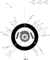
- Fig. 3 is a snapshot illustrating a cross sectional view of another optical fiber cable 300 substantially similar to the optical fiber cable 100, in terms of structural and functional aspects and the like elements of the optical fiber cable 100.
- the tensile yarns 108 may be 3 tensile yarns i.e., 108a, 108b, and 108c.
- the centre 118 of the overlap portion 116 of the deformable layer 106 and the centre 120a of the tensile yarn 108a of the tensile yarns 108 are separated by at least 60° angular distance with respect to centre of the cable 300 at least one cross section of the optical fiber cable 300.
- the centre 120a of the tensile yarn 108a of the tensile yarns 108 and centre 120b of the tensile yarn 108b of the tensile yarns 108 are separated by at least 30° angular distance with respect to centre of the cable 300 at least one cross section of the optical fiber cable 300. Further, the centre 120b of the tensile yarn 108b of the tensile yarns 108 and centre 120c of the tensile yarn 108c of the tensile yarns 108 are separated by at least 30° angular distance with respect to centre of the cable 300 at least one cross section of the optical fiber cable 300.
- the optical fiber cable (100) characterizes an optical fiber (102), a buffer layer (104) that surrounds the optical fiber (102) to define a tight buffered optical fiber (112), a deformable layer (106) wrapped around the tight buffered optical fiber (112), where the deformable layer (106) has two longitudinal overlap ends (114a, 114b) that defines an overlap portion (116), one or more tensile yarns (108a-108n) disposed above the deformable layer (106) and a sheath (110) that surrounds the deformable layer (106) and the one or more tensile yarns (108a-108n).
- the centre (118) of the overlap portion (116) of the deformable layer (106) and centre (120) of a tensile yarn of the one or more tensile yarns (108a-108n) is separated by a predefined angular distance with respect to the centre of the cable (100) at atleast one cross section along a length of the optical fiber cable (100). Moreover, the angular distance between the centres of two or more tensile yarns of the one or more tensile yarns (108a-108n) is greater than or equal to 30 degrees (30°) with respect to centre of the optical fiber cable (100).
- the width of the overlap portion (116) is less than 4 millimetres (mm).
- the centre (118) of the overlap portion (116) of the deformable layer (106) and the centre (120) of the tensile yarn of the one or more tensile yarns (108a-108n) is separated by ⁇ 90° angular distance with respect to centre of the optical fiber cable (100) at minimum one cross section of the optical fiber cable (100).
- the optical fiber (102) undergoes a strain of less than 0.34% at an aerial load up to 150 N. Further, the stripping force of the tight buffered optical fiber (112) is in a range between 1 N and 12 N for a sample of 20 mm tight buffered optical fiber.
- the essential components of the invention includes a deformable layer, one or more tensile yarns positioned at specific angular orientations, and a protective sheath.
- the components collectively serve to prevent fiber retraction and significantly improve cable performance, particularly in the face of extreme operating conditions.
- the collaboration between the deformable layer and the specified tensile yarns functions synergistically to prevent fiber retraction, ensuring an optimal and consistent coupling with surrounding layers.
- the integration of components embodies an approach, offering enhanced reliability and performance in addressing the challenges associated with fiber retraction in optical fiber cables.
- the precise angular positioning of the tensile yarns plays a pivotal role in achieving uniform coupling between the tight buffer unit and the sheath, thereby presenting a robust and highly effective solution to the identified problem.
- the present invention pertains to mitigating the challenge of fiber retraction and associated connectivity loss observed in optical fiber cables, specifically under maximum load conditions.
- the optical fiber cable 100 minimize the fiber retraction in the tight buffered cable and facilitate to uniformly couple the tight buffer with an inner surface of the sheath 110.
- the tensile yarns 108 may be strategically positioned outside the deformable layer 106 ensures a uniform coupling of the tight buffer with the sheath 110 at a plurality of locations and minimizes the fiber retraction during or after installation of the optical fiber cable 100 thereby making the optical fiber cable 100 easy to install.
- the unique placement of the tensile yarns 108 above the deformable layer 106 inside the optical fiber cable 100 may provide minimized fibre module retraction in operating conditions while having safe cable break technology.
- the unique placement of the tensile yarns 108 may keep strain produced at installation load of upto 150N, less than 0.34%.
- the disclosed invention provides several other advantages, including achieving an optimal cable dimension, optimizing breaking load, cost-effectiveness, and a positive impact on overall cable performance. These collective benefits contribute to a more robust and efficient optical fiber cable system, surpassing the limitations of existing solutions.
- the disclosed invention effectively prevents fiber retraction and improves cable performance in real-world operating conditions.
- This adaptability makes it well-suited for critical applications where optimal dimensions and connectivity are paramount, such as aerial installations or deployments under tension.
- the invention encompasses diverse optical fiber cable configurations incorporating deformable layers, tensile yarns, and specific angular distances. This inclusive approach offers a versatile solution to industry-wide challenges concerning fiber retraction and connectivity loss.
- Disjunctive language such as the phrase "at least one of X, Y, Z," unless specifically stated otherwise, is otherwise understood with the context as used in general to present that an item, term, etc., may be either X, Y, or Z, or any combination thereof (e.g., X, Y, and/or Z). Thus, such disjunctive language is not generally intended to, and should not, imply that certain embodiments require at least one of X, at least one of Y, or at least one of Z to each be present.
Landscapes
- Physics & Mathematics (AREA)
- General Physics & Mathematics (AREA)
- Optics & Photonics (AREA)
- Light Guides In General And Applications Therefor (AREA)
Applications Claiming Priority (1)
| Application Number | Priority Date | Filing Date | Title |
|---|---|---|---|
| IN202311028463 | 2023-04-19 |
Publications (2)
| Publication Number | Publication Date |
|---|---|
| EP4451031A2 true EP4451031A2 (de) | 2024-10-23 |
| EP4451031A3 EP4451031A3 (de) | 2025-01-29 |
Family
ID=90789244
Family Applications (1)
| Application Number | Title | Priority Date | Filing Date |
|---|---|---|---|
| EP24170942.7A Pending EP4451031A3 (de) | 2023-04-19 | 2024-04-18 | Dichtes gepuffertes faseroptisches kabel |
Country Status (3)
| Country | Link |
|---|---|
| US (1) | US20240353637A1 (de) |
| EP (1) | EP4451031A3 (de) |
| AU (1) | AU2024202500A1 (de) |
Citations (4)
| Publication number | Priority date | Publication date | Assignee | Title |
|---|---|---|---|---|
| US20100150505A1 (en) | 2008-12-12 | 2010-06-17 | Draka Comteq, B.V. | Buffered Optical Fiber |
| EP2409190B1 (de) | 2009-03-16 | 2016-10-19 | Prysmian S.p.A. | Optisches kabel mit verbesserter abisolierbarkeit |
| KR20220051570A (ko) | 2020-10-19 | 2022-04-26 | 엘에스전선 주식회사 | 광케이블 |
| US20220373752A1 (en) | 2020-10-27 | 2022-11-24 | Superior Essex International LP | Tight buffered optical fibers that resist shrinkage |
Family Cites Families (4)
| Publication number | Priority date | Publication date | Assignee | Title |
|---|---|---|---|---|
| KR100323143B1 (ko) * | 1998-03-25 | 2002-02-04 | 추후제출 | 광섬유 케이블 및 그 제조방법 |
| AU2001255863A1 (en) * | 2000-04-28 | 2001-11-12 | Corning Cable Systems Llc | Fiber optic cable |
| WO2010080343A1 (en) * | 2008-12-19 | 2010-07-15 | Corning Cable Systems Llc | Methods of controlling bonding and water blocking in cables |
| US9482839B2 (en) * | 2013-08-09 | 2016-11-01 | Corning Cable Systems Llc | Optical fiber cable with anti-split feature |
-
2024
- 2024-04-17 AU AU2024202500A patent/AU2024202500A1/en active Pending
- 2024-04-18 EP EP24170942.7A patent/EP4451031A3/de active Pending
- 2024-04-19 US US18/640,059 patent/US20240353637A1/en active Pending
Patent Citations (4)
| Publication number | Priority date | Publication date | Assignee | Title |
|---|---|---|---|---|
| US20100150505A1 (en) | 2008-12-12 | 2010-06-17 | Draka Comteq, B.V. | Buffered Optical Fiber |
| EP2409190B1 (de) | 2009-03-16 | 2016-10-19 | Prysmian S.p.A. | Optisches kabel mit verbesserter abisolierbarkeit |
| KR20220051570A (ko) | 2020-10-19 | 2022-04-26 | 엘에스전선 주식회사 | 광케이블 |
| US20220373752A1 (en) | 2020-10-27 | 2022-11-24 | Superior Essex International LP | Tight buffered optical fibers that resist shrinkage |
Also Published As
| Publication number | Publication date |
|---|---|
| US20240353637A1 (en) | 2024-10-24 |
| EP4451031A3 (de) | 2025-01-29 |
| AU2024202500A1 (en) | 2024-11-07 |
Similar Documents
| Publication | Publication Date | Title |
|---|---|---|
| US9042693B2 (en) | Water-soluble water-blocking element | |
| DK2204681T3 (en) | An optical fiber cable, comprising a perforated water-blocking element | |
| AU2014337301B2 (en) | Armored flexible fiber optic assembly | |
| EP3447558B1 (de) | Glasfaserbandkanalkabel | |
| US6922511B2 (en) | Fiber optic assemblies and cables having subunits with a security feature | |
| EP0373846B1 (de) | Voll dielektrisches Kabel mit leicht zugänglichen Adern | |
| EP4206771A1 (de) | Faseroptisches kabel mit beweglichem reissfaden | |
| US11619797B2 (en) | Dielectric predictable break load aerial drop cable | |
| US9921380B2 (en) | Composite cable | |
| US20240353637A1 (en) | Tight buffered optical fiber cable | |
| US10558005B2 (en) | Fiber optic assembly with rigid wire push material | |
| US20160195686A1 (en) | Armored Flexible Fiber Optic Assembly | |
| AU2024202778A1 (en) | Optical fiber cable with embedded strength members | |
| EP3355092A1 (de) | Optische faser für innenanwendungen | |
| US20210116658A1 (en) | Optical fibre ribbon with thin matrix material layer | |
| EP4468049A1 (de) | Faseroptisches kabel mit mehreren schlitzen | |
| EP4421549A2 (de) | Faseroptisches freileitungskabel | |
| EP4198594A1 (de) | Leichtgewichtiges glasfaserkabel | |
| EP4485031A1 (de) | Faseroptisches kabel mit einem oder mehreren schrumpfschutzelementen | |
| EP4579304A1 (de) | Faseroptisches kabel mit einer fest gepufferten multifasereinheit | |
| EP4212931A1 (de) | Faseroptisches kabel mit eingebetteten verstärkungselementen | |
| EP4212935A1 (de) | Faseroptisches kabel mit mehrschichtigen rohren | |
| EP4212933A1 (de) | Faseroptisches kabel mit flexiblen wickelschläuchen | |
| EP3355089B1 (de) | Optische faser für innenanwendungen | |
| KR20260012122A (ko) | 광점퍼 케이블 |
Legal Events
| Date | Code | Title | Description |
|---|---|---|---|
| PUAI | Public reference made under article 153(3) epc to a published international application that has entered the european phase |
Free format text: ORIGINAL CODE: 0009012 |
|
| STAA | Information on the status of an ep patent application or granted ep patent |
Free format text: STATUS: THE APPLICATION HAS BEEN PUBLISHED |
|
| AK | Designated contracting states |
Kind code of ref document: A2 Designated state(s): AL AT BE BG CH CY CZ DE DK EE ES FI FR GB GR HR HU IE IS IT LI LT LU LV MC ME MK MT NL NO PL PT RO RS SE SI SK SM TR |
|
| PUAL | Search report despatched |
Free format text: ORIGINAL CODE: 0009013 |
|
| AK | Designated contracting states |
Kind code of ref document: A3 Designated state(s): AL AT BE BG CH CY CZ DE DK EE ES FI FR GB GR HR HU IE IS IT LI LT LU LV MC ME MK MT NL NO PL PT RO RS SE SI SK SM TR |
|
| RIC1 | Information provided on ipc code assigned before grant |
Ipc: G02B 6/44 20060101AFI20241223BHEP |
|
| STAA | Information on the status of an ep patent application or granted ep patent |
Free format text: STATUS: REQUEST FOR EXAMINATION WAS MADE |
|
| 17P | Request for examination filed |
Effective date: 20250729 |