EP4451013A1 - Lidar and vehicle - Google Patents
Lidar and vehicle Download PDFInfo
- Publication number
- EP4451013A1 EP4451013A1 EP22914981.0A EP22914981A EP4451013A1 EP 4451013 A1 EP4451013 A1 EP 4451013A1 EP 22914981 A EP22914981 A EP 22914981A EP 4451013 A1 EP4451013 A1 EP 4451013A1
- Authority
- EP
- European Patent Office
- Prior art keywords
- substrate
- bracket
- lidar
- laser
- circuit board
- Prior art date
- Legal status (The legal status is an assumption and is not a legal conclusion. Google has not performed a legal analysis and makes no representation as to the accuracy of the status listed.)
- Pending
Links
Images



Classifications
-
- G—PHYSICS
- G01—MEASURING; TESTING
- G01S—RADIO DIRECTION-FINDING; RADIO NAVIGATION; DETERMINING DISTANCE OR VELOCITY BY USE OF RADIO WAVES; LOCATING OR PRESENCE-DETECTING BY USE OF THE REFLECTION OR RERADIATION OF RADIO WAVES; ANALOGOUS ARRANGEMENTS USING OTHER WAVES
- G01S17/00—Systems using the reflection or reradiation of electromagnetic waves other than radio waves, e.g. lidar systems
- G01S17/88—Lidar systems specially adapted for specific applications
- G01S17/93—Lidar systems specially adapted for specific applications for anti-collision purposes
- G01S17/931—Lidar systems specially adapted for specific applications for anti-collision purposes of land vehicles
-
- G—PHYSICS
- G01—MEASURING; TESTING
- G01S—RADIO DIRECTION-FINDING; RADIO NAVIGATION; DETERMINING DISTANCE OR VELOCITY BY USE OF RADIO WAVES; LOCATING OR PRESENCE-DETECTING BY USE OF THE REFLECTION OR RERADIATION OF RADIO WAVES; ANALOGOUS ARRANGEMENTS USING OTHER WAVES
- G01S17/00—Systems using the reflection or reradiation of electromagnetic waves other than radio waves, e.g. lidar systems
- G01S17/02—Systems using the reflection of electromagnetic waves other than radio waves
-
- G—PHYSICS
- G01—MEASURING; TESTING
- G01S—RADIO DIRECTION-FINDING; RADIO NAVIGATION; DETERMINING DISTANCE OR VELOCITY BY USE OF RADIO WAVES; LOCATING OR PRESENCE-DETECTING BY USE OF THE REFLECTION OR RERADIATION OF RADIO WAVES; ANALOGOUS ARRANGEMENTS USING OTHER WAVES
- G01S17/00—Systems using the reflection or reradiation of electromagnetic waves other than radio waves, e.g. lidar systems
- G01S17/02—Systems using the reflection of electromagnetic waves other than radio waves
- G01S17/06—Systems determining position data of a target
- G01S17/08—Systems determining position data of a target for measuring distance only
-
- G—PHYSICS
- G01—MEASURING; TESTING
- G01S—RADIO DIRECTION-FINDING; RADIO NAVIGATION; DETERMINING DISTANCE OR VELOCITY BY USE OF RADIO WAVES; LOCATING OR PRESENCE-DETECTING BY USE OF THE REFLECTION OR RERADIATION OF RADIO WAVES; ANALOGOUS ARRANGEMENTS USING OTHER WAVES
- G01S7/00—Details of systems according to groups G01S13/00, G01S15/00, G01S17/00
- G01S7/48—Details of systems according to groups G01S13/00, G01S15/00, G01S17/00 of systems according to group G01S17/00
- G01S7/481—Constructional features, e.g. arrangements of optical elements
-
- G—PHYSICS
- G01—MEASURING; TESTING
- G01S—RADIO DIRECTION-FINDING; RADIO NAVIGATION; DETERMINING DISTANCE OR VELOCITY BY USE OF RADIO WAVES; LOCATING OR PRESENCE-DETECTING BY USE OF THE REFLECTION OR RERADIATION OF RADIO WAVES; ANALOGOUS ARRANGEMENTS USING OTHER WAVES
- G01S7/00—Details of systems according to groups G01S13/00, G01S15/00, G01S17/00
- G01S7/48—Details of systems according to groups G01S13/00, G01S15/00, G01S17/00 of systems according to group G01S17/00
- G01S7/481—Constructional features, e.g. arrangements of optical elements
- G01S7/4811—Constructional features, e.g. arrangements of optical elements common to transmitter and receiver
- G01S7/4813—Housing arrangements
-
- G—PHYSICS
- G01—MEASURING; TESTING
- G01S—RADIO DIRECTION-FINDING; RADIO NAVIGATION; DETERMINING DISTANCE OR VELOCITY BY USE OF RADIO WAVES; LOCATING OR PRESENCE-DETECTING BY USE OF THE REFLECTION OR RERADIATION OF RADIO WAVES; ANALOGOUS ARRANGEMENTS USING OTHER WAVES
- G01S7/00—Details of systems according to groups G01S13/00, G01S15/00, G01S17/00
- G01S7/48—Details of systems according to groups G01S13/00, G01S15/00, G01S17/00 of systems according to group G01S17/00
- G01S7/481—Constructional features, e.g. arrangements of optical elements
- G01S7/4817—Constructional features, e.g. arrangements of optical elements relating to scanning
-
- Y—GENERAL TAGGING OF NEW TECHNOLOGICAL DEVELOPMENTS; GENERAL TAGGING OF CROSS-SECTIONAL TECHNOLOGIES SPANNING OVER SEVERAL SECTIONS OF THE IPC; TECHNICAL SUBJECTS COVERED BY FORMER USPC CROSS-REFERENCE ART COLLECTIONS [XRACs] AND DIGESTS
- Y02—TECHNOLOGIES OR APPLICATIONS FOR MITIGATION OR ADAPTATION AGAINST CLIMATE CHANGE
- Y02A—TECHNOLOGIES FOR ADAPTATION TO CLIMATE CHANGE
- Y02A90/00—Technologies having an indirect contribution to adaptation to climate change
- Y02A90/10—Information and communication technologies [ICT] supporting adaptation to climate change, e.g. for weather forecasting or climate simulation
Definitions
- This application relates to the field of radar technologies, and in particular, to a lidar and a vehicle.
- a lidar Light Detection and Ranging, Lidar
- Lidar Light Detection and Ranging, Lidar
- An operating principle of the lidar is to transmit a detection signal (a laser beam) to the target, then compare a received signal (a target echo) reflected from the target with the transmitted signal, and perform appropriate processing to obtain related information about the target, such as a parameter including a target distance, an orientation, a height, a speed, a posture, even a shape, and the like, to detect, track, and identify the target.
- the lidar may include a laser and a photodetector.
- the laser may convert an electrical pulse into an optical pulse and transmit the optical pulse, and the photodetector restores, to an electrical pulse, an optical pulse reflected from the target.
- no temperature control apparatus for cooling or heating the laser is disposed.
- a wavelength of a laser beam output by the laser is affected by a temperature of the laser.
- the corresponding photodetector has a specific requirement for a wavelength range of a received laser beam. If a temperature deviation of the laser is excessively large, a wavelength deviation of the laser beam is excessively large, and some laser energy exceeds a receivable wavelength range of the photodetector. This affects performance of the lidar.
- Embodiments of this application provide a lidar and a vehicle, to resolve a temperature control problem of a laser.
- An aspect of embodiments of this application provides a lidar, including a bracket and an emission assembly.
- the emission assembly includes a substrate, a circuit board, an optical lens, a laser, and a temperature control device, the substrate is connected to the bracket, the optical lens and the circuit board are separately connected to a side that is of the substrate and that backs onto the bracket, the laser is connected to a side that is of the circuit board and that backs onto the substrate, the temperature control device is connected to a side that is of the circuit board and that faces the substrate, a hole is disposed in the substrate, the temperature control device and the bracket are connected to each other in the hole, and a thermal gel is disposed between the temperature control device and the bracket.
- the laser is fastened to the circuit board, components of the laser and the circuit board are fastened to the substrate, and the optical lens is fastened to the substrate, so that the laser and the optical lens that are most sensitive to precision are finally fastened to a same module, that is, the substrate.
- the temperature control device is disposed to implement active temperature control, so that a temperature control problem of the laser can be resolved, and impact of a temperature on a wavelength of a laser beam emitted by the laser is avoided.
- the substrate includes a main body part and a support, the support is connected to a side wall of the main body part, a plane on which the support is located is perpendicular to a plane on which the main body part is located, the support is located on a side that is of the main body part and that faces the circuit board, the circuit board is connected to the main body part, the optical lens is connected to the support, the laser is located at an end that is of the circuit board and that is close to the optical lens, and the laser and the optical lens are disposed opposite to each other.
- the substrate has two parts of structures, respectively configured to carry the laser and the optical lens. On a basis that the laser and the optical lens are integrated on the same substrate, the optical lens can be aligned with the laser. Space utilization is appropriate.
- the temperature control device is a thermo electric cooler, and the thermo electric cooler is configured to heat or cool the circuit board.
- the thermo electric cooler can raise a temperature of the laser when an external ambient temperature is low, and lower the temperature of the laser when the external ambient temperature is high. In this way, the temperature of the laser is in a constant range, and the impact of the temperature on the wavelength of the laser beam emitted by the laser is avoided.
- a coefficient of thermal expansion of the substrate is less than 10 PPM.
- the substrate is set to have a low coefficient of thermal expansion, so that a large deviation of size precision between the laser and the optical lens caused by the thermal expansion and cold contraction effect at high and low temperatures can be avoided.
- the coefficient of thermal expansion of the substrate ranges from 4 PPM to 10 PPM.
- the coefficient of thermal expansion of the substrate is set to range from 4 PPM to 10 PPM. This is more likely to implement, and an adhesive between the substrate and the bracket is not prone to cracking.
- an absolute value of a difference between the coefficient of thermal expansion of the substrate and a coefficient of thermal expansion of the circuit board is less than or equal to 2 PPM.
- the substrate is made of a material including a kovar alloy, ceramic, or glass.
- the kovar alloy, the ceramic, or the glass is disposed as the substrate, so that a low coefficient of thermal expansion requirement of the substrate can be met.
- the circuit board is made of a material including aluminum nitride ceramic.
- the aluminum nitride ceramic is disposed as the circuit board, so that a high thermal conductivity requirement and a low coefficient of thermal expansion requirement of the circuit board can be met.
- the bracket is made of a material including an aluminum alloy.
- the aluminum alloy is disposed as the bracket, so that a structural strength requirement and a high thermal conductivity requirement of the bracket can be met.
- each of two ends of the circuit board is fastened to the substrate by using a cushion block
- the cushion block is a part of a structure protruding from a surface of the substrate, or the cushion block is a structure independent of the substrate and is fastened to the substrate.
- the cushion block can reduce a contact area between the substrate and the circuit board, increase space between the substrate and the circuit board, and reduce heat backflow effect.
- both a length and a width of the cushion block are less than 3 mm.
- the cushion block has a small area, so that the heat backflow effect is minimized.
- the lidar further includes a buffer sheet, the buffer sheet is located between the bracket and the substrate, the buffer sheet is bonded to the bracket by using an adhesive, and the buffer sheet is welded to the substrate, or the buffer sheet is bonded to the substrate by using an adhesive.
- the buffer sheet can improve reliability of bonding between the substrate and the bracket.
- the buffer sheet can overcome a stress caused by a mismatch between the coefficient of thermal expansion of the substrate and a coefficient of thermal expansion of the bracket.
- a coefficient of thermal expansion of the buffer sheet is greater than the coefficient of thermal expansion of the substrate, and the coefficient of thermal expansion of the buffer sheet is less than the coefficient of thermal expansion of the bracket.
- an installation column is disposed on a side that is of the substrate and that faces the bracket
- an installation hole is disposed on a side that is of the bracket and that faces the substrate
- the installation column is located in the installation hole
- a gap between the installation column and the installation hole is filled with an adhesive.
- Adhesive bonding between the installation column and the installation hole can increase adhesive bonding strength between the substrate and the bracket, so that reliability of the adhesive can be further met in cases of high and low temperatures and shock vibration.
- the lidar includes an optical machine
- the optical machine includes the bracket, the emission assembly, and a receiving assembly
- the receiving assembly and the emission assembly are separately fastened to the bracket.
- the bracket is configured to install the emission assembly and the receiving assembly, so that optical precision machines in the lidar are integrated together to improve integration of a structure.
- the lidar further includes a housing and a scanner, both the optical machine and the scanner are installed on the housing, and a light output axis of the optical machine is aligned with a rotation mirror of the scanner.
- a laser beam emitted by the optical machine is reflected by the rotation mirror, and the optical machine is aligned with the rotation mirror, to ensure that all the laser beams emitted by the optical machine are reflected by the rotation mirror. This ensures a field of view range of the lidar.
- a pin is disposed on the housing, a kidney-shaped hole is provided in the bracket, a length direction of the kidney-shaped hole is perpendicular to the light output axis, the pin is installed in the kidney-shaped hole, and a location of the pin in the kidney-shaped hole can be adjusted.
- the location of the optical machine can be adjusted when assembled on the housing. This helps improve location precision between the optical machine and the rotation mirror, so that the lidar can achieve a larger FOV
- the optical lens is bonded to the substrate by using an adhesive
- the circuit board is bonded to the substrate by using an adhesive.
- the optical lens and the circuit board are separately bonded to the substrate by using an adhesive, so that fastening reliability can be ensured.
- At least one slot is provided on a side wall of the substrate.
- the slot is disposed to reduce a thermal conduction area of the substrate and to reduce the heat backflow effect.
- Another aspect of embodiments of this application provides a vehicle, including a vehicle body and the foregoing lidar.
- the lidar is fastened to the vehicle body.
- An embodiment of this application provides a vehicle.
- the lidar provided in the foregoing embodiments of this application can reduce impact of the temperature on performance of the lidar, and provide performance of a large field of view. This helps improve performance such as ranging of the vehicle, and facilitates intelligence of the vehicle.
- An embodiment of this application provides a lidar and a vehicle.
- the laser is fastened to a circuit board, components of the laser and the circuit board and an optical lens are fastened to a same substrate, and a temperature control device is used to actively control a temperature of the laser, so that an operating temperature of the laser can be accurately controlled not to exceed a standard. This avoids impact of the temperature on a laser wavelength.
- a deviation of size precision between the laser and the optical lens at high and low temperatures can be avoided, so that optical performance of the lidar can be improved.
- a buffer sheet and a fitting structure of an installation column and an installation hole are disposed.
- a kidney-shaped hole is designed in the bracket to match a pin designed on a housing, so that a location of an optical machine relative to the housing can be adjusted in one direction and fastened. This implements precise alignment of a relative location of the optical machine and a scanner, and a large field of view is achieved.
- the temperature control device is disposed, so that the temperature of the laser can be constantly controlled at 75 ⁇ 5°C at an external ambient temperature of -40°C to +85°C.
- the laser and the optical lens are integrated on the same substrate, and the substrate is disposed to be made of a material with a low coefficient of thermal expansion, so that a size deviation between the laser and the optical lens can be controlled to be less than 5 microns at the external ambient temperature of -40°C to +85°C.
- the location of the optical machine is set to be adjustable, so that performance of a large field of view of 140 degrees can be achieved.
- a lidar is a radar system that emits a laser beam to detect characteristics such as a location, a speed, and the like of a target, has advantages such as high resolution, good concealment, a strong anti-active interference capability, a small size, and the like, and is widely used in fields such as resource exploration, traffic communication, environment monitoring, and the like.
- the lidar may be mounted on a vehicle as an important part of an intelligent driving environment sensing system.
- the vehicle-mounted lidar has advantages such as accurate acquisition of three-dimensional information of the target, high resolution, a strong anti-interference capability, a wide detection range, near-all-weather operation, and the like.
- FIG. 1 is a schematic diagram of a structure of a vehicle according to an embodiment of this application.
- An aspect of embodiments of this application provides a vehicle.
- the vehicle includes a vehicle body and a lidar 100 mounted on the vehicle body.
- the lidar 100 may be mounted at a location such as front, left front, right front, rear, or the like of the vehicle body, to detect a larger coverage area and to improve driving environment safety of the vehicle.
- FIG. 2 is a schematic diagram of a detection range of a lidar on a vehicle according to an embodiment of this application.
- An example in which the lidar 100 is disposed at three locations of a front, a left front, and a right front of the vehicle body is used.
- a detection field of view of the lidar 100 is an FOV
- a larger FOV indicates a larger coverage area that can be detected. That is, the FOV is a key performance parameter of the lidar 100.
- an optical machine is a key core component of the vehicle-mounted lidar, and needs to output a stable high-quality laser beam and accurately receive a reflected laser beam within an entire life cycle of the vehicle.
- the optical machine may include an emission assembly and a receiving assembly.
- the emission assembly is configured to output a laser wavelength
- the receiving assembly is configured to receive a laser beam reflected from a target
- a core component of the emission assembly is a laser.
- the wavelength of the laser beam output by the laser is affected by a temperature of the laser, and the corresponding receiving assembly also has a specific requirement for a wavelength range of a received laser beam. If a temperature deviation of the laser is excessively large, a wavelength deviation of the laser beam is excessively large, and some laser energy exceeds a receivable wavelength range of the receiving assembly. This affects receiving efficiency and further affects a performance indicator of a detection distance. Therefore, how to perform temperature control design of the laser is one of the difficulties in the structural design of the lidar.
- a mainstream laser of the lidar is an edge emitting laser (Edge Emitting Laser, EEL).
- EEL Edge Emitting Laser
- the EEL has advantages such as a high peak optical power, high energy efficiency, and the like, and is a preferred light source of a long-distance vehicle-mounted lidar product. How to control a temperature of the optical machine using the EEL is also a currently key challenge in structural design of the optical machine of the lidar.
- the waveform of the laser beam directly output by the laser generally does not meet a condition for direct use of the lidar, and an optical lens needs to be used for beam shaping.
- size precision between the laser and the optical lens affects laser quality. Based on an optical design requirement, the size precision between the laser and the optical lens needs to be maintained at a micron level in an entire life cycle. Machining precision and bonding reliability of components and parts, and impact of thermal expansion and cold contraction caused by a temperature change of the components and parts lead to change of the size precision between the laser and the optical lens. Therefore, how to implement a design of controlling size precision between the laser and the optical lens is one of challenges in a current design.
- the laser and a peripheral circuit may be installed on a thermo electric cooler (Thermo Electric Cooler, TEC), and are fastened to an outer housing of the lidar together with the optical lens.
- TEC Thermo Electric Cooler
- weights of the laser and the peripheral circuit are on the TEC, and in a vibration scenario, requirements for strength of the TEC and corresponding fastening strength are high.
- the laser is fastened to the outer housing by using the TEC, and the optical lens is directly fastened to the outer housing. Therefore, the TEC also participates in a process of locating a size between the laser and the lens. In thermal expansion and cold contraction effect caused by a temperature change, the size precision between the optical lens and the laser is further affected by the TEC. This is not conducive to shortening a size chain of a location relationship between the optical lens and the laser.
- the laser is carried by using the thermo electric cooler.
- the TEC may be used to control the temperature of the laser, this technology is applicable only to a case in which the sizes of the laser and the peripheral circuit are small, for example, in a scenario in which an optical fiber laser, an optical module, or the like is used, and cannot be applicable to a scenario in which a large-sized lidar using an EEL laser is used.
- an embodiment of this application provides a lidar.
- An optical lens and a laser are fastened to a same substrate, and a temperature control device is used to actively control a temperature of the laser, so that impact of the temperature on the laser wavelength is avoided.
- size precision between the laser and the optical lens can be reduced, and optical performance of the lidar can be improved.
- FIG. 3 is a schematic diagram of an external structure of the lidar according to an embodiment of this application.
- FIG. 4 is a schematic diagram of an internal structure of the lidar according to an embodiment of this application. Refer to FIG. 3 and FIG. 4 .
- the lidar 100 provided in this embodiment of this application may include a housing 11, and an optical machine 12 and a scanner 13 that are disposed inside the housing 11.
- the housing 11 may include an upper housing and a lower housing (not marked in the figure).
- the upper housing and the lower housing may be fastened in a manner of bonding, screw connection, or the like, to form accommodating space for accommodating the optical machine 12 and the scanner 13.
- the optical machine 12 and the scanner 13 may be separately fastened to the housing 11, for example, may be fastened to a bottom wall of the lower housing (in the figure, a positive direction of a Y-axis is an upper direction, and a negative direction is a lower direction).
- the optical machine 12 is configured to emit and receive a laser beam.
- a rotation mirror is disposed in the scanner 13. The laser beam emitted by the optical machine 12 may be illuminated on a reflective surface of the rotation mirror and then be reflected.
- a light output axis of the optical machine 12 may be aligned with the rotation mirror of the scanner 13.
- the optical machine 12 and the scanner 13 may be spaced on a Z-axis, and the light output axis of the optical machine 12 may extend in a Z direction in the figure.
- an information processing system (not marked in the figure) is further disposed inside the housing 11.
- the information processing system is configured to process a laser signal received by the optical machine 12.
- Another component is further disposed inside the housing 11. Details are not described herein. It should be understood that the optical machine 12 is configured to output a stable high-quality laser beam and can accurately receive a reflected laser beam, and is a key core component of the lidar 100.
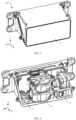
- FIG. 5 is a schematic diagram of a structure of an optical machine according to an embodiment of this application.
- FIG. 6 is a schematic exploded view of an optical machine according to an embodiment of this application.
- an optical machine 12 may include a bracket 21, emission assemblies 22, and a receiving assembly 23.
- the receiving assembly 23 and the emission assemblies 22 may be separately fastened to the bracket 21.
- the bracket 21 may include a first accommodation cavity 211, a second accommodation cavity 212, and a third accommodation cavity 213.
- the first accommodation cavity 211 and the second accommodation cavity 212 are respectively configured to accommodate the emission assemblies 22, and the third accommodation cavity 213 is configured to accommodate the receiving assembly 23.
- Structures of the two emission assemblies 22 are mirror-symmetric, structures of the first accommodation cavity 211 and the second accommodation cavity 212 are mirror-symmetric, and the first accommodation cavity 211 and the second accommodation cavity 212 may be respectively disposed on two adjacent side surfaces of the bracket 21.
- an opening direction of the first accommodation cavity 211 is a positive direction of an X-axis
- an opening direction of the second accommodation cavity 212 is a positive direction of a Z-axis.
- the third accommodation cavity 213 is located above the first accommodation cavity 211 and the second accommodation cavity 212, and is disposed as a structure of a ring-shaped through hole.
- the receiving assembly 23 is disposed in the ring-shaped through hole in a penetrating manner. Specific structures of the third accommodation cavity 213 and the receiving assembly 23 are not specifically described in this application.
- the optical machine 12 may further include a mirror group 24.
- the mirror group 24 may be connected to the bracket 21, and is located between the first accommodation cavity 211 and the second accommodation cavity 212. Laser beams emitted by the two emission assemblies 22 may enter the mirror group 24, converge in the mirror group 24, and then are emitted outward.
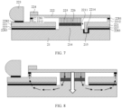
- FIG. 7 is a schematic diagram of a simplified structure of an emission assembly and a bracket according to an embodiment of this application. It should be understood that FIG. 7 shows a part of a structure of the bracket 21, that is, a sectional view corresponding to one emission assembly 22. Refer to FIG. 7 .
- the emission assembly 22 may include a substrate 221, a circuit board 222, an optical lens 223, a laser 224, and a temperature control device 225.
- the substrate 221 may be connected to the bracket 21, the optical lens 223 and the circuit board 222 may be separately connected to a side that is of the substrate 221 and that backs onto the bracket 21, the laser 224 may be connected to a side that is of the circuit board 222 and that backs onto the substrate 221, the temperature control device 225 may be connected to a side that is of the circuit board 222 and that faces the substrate 221, a hole 2211 is disposed in the substrate 221, the temperature control device 225 and the bracket 21 are connected to each other in the hole 2211, and a thermal gel 226 is disposed between the temperature control device 225 and the bracket 21.
- the laser 224 may be welded above the circuit board 222, the circuit board 222 may be bonded to the substrate 221 by using a first adhesive 2281, the optical lens 223 may be bonded to the substrate 221 by using a second adhesive 2282, and the substrate 221 may be bonded to the bracket 21 by using a third adhesive 2283.
- the laser 224 may be disposed at an end that is of the circuit board 222 and that is close to the optical lens 223, so that the laser 224 and the optical lens 223 are disposed close and opposite to each other.
- the lidar 100 may further include a buffer sheet 227.
- the buffer sheet 227 is located between the bracket 21 and the substrate 221.
- the buffer sheet 227 may be welded to the substrate 221, or the buffer sheet 227 may be bonded to the substrate 221 by using an adhesive, and the buffer sheet 227 may be bonded to the bracket 21 by using the third adhesive 2283.
- the optical lens 223 may be in a form of a double convex thick aspheric lens, and is configured to collimate diverged light emitted by the laser 224.
- the laser 224 may be an edge emitting laser (Edge Emitting Laser, EEL), for example, may be a four-channel or an eight-channel laser.
- EEL Edge Emitting Laser
- the temperature control device 225 is connected to the bracket 21.
- the temperature control device 225 is a device for temperature control, and may be configured to heat the laser 224 when an external ambient temperature is low or cool the laser 224 when an external ambient temperature is high, so that a temperature of the laser 224 is in a constant range. This avoids impact of a temperature on a wavelength of a laser beam emitted by the laser 224.
- a specific type of the temperature control device 225 is not specifically limited in this embodiment of this application.
- the temperature control device 225 may be a thermo electric cooler TEC, and may be controlled to cool or heat the circuit board 222 and the laser 224 by switching positive and negative electrodes of the thermo electric cooler.
- a location in which the temperature control device 225 is connected to the substrate 221 may be maximumly close to the laser 224, to improve heat transfer efficiency.
- a hole 2211 is disposed in the substrate 221, so that the temperature control device 225 may be connected to the bracket 21 in the hole 2211, to smoothly transfer heat to the bracket 21.
- the temperature control device 225 is connected to the bracket 21, to transfer heat to the bracket 21.
- the temperature control device 225 may transfer the heat to the bracket 21 by using the thermal gel 226, to improve heat dissipation efficiency.
- a thickness of the thermal gel 226 may be less than 1.5 mm, and a thermal conductivity coefficient of the thermal gel 226 may be 5 W/m ⁇ K to 15 W/m ⁇ K.
- the bracket 21 is configured to fasten and install the substrate 221, to implement heat dissipation for the laser 224.
- the bracket 21 may be made of a metal such as an aluminum alloy through die casting or through machining an aluminum profile.
- a coefficient of thermal expansion of a manufacturing material of the bracket 21 may range from 21 PPM to 24 PPM, for example, may be approximately 23 PPM.
- a thermal conductivity coefficient of the bracket 21 may range from 140 W/m ⁇ K to 200 W/m ⁇ K.
- the substrate 221 is configured to carry the optical lens 223 and the laser 224, and may be made of a material with a low coefficient of thermal expansion (Coefficient of thermal expansion, CTE) and a low thermal conductivity coefficient.
- a coefficient of thermal expansion of the substrate 221 is less than a coefficient of thermal expansion of the bracket 21, and the coefficient of thermal expansion of the substrate 221 may be less than or equal to 10 PPM.
- a coefficient of thermal expansion of the buffer sheet 227 may be greater than the coefficient of thermal expansion of the substrate 221, and is less than the coefficient of thermal expansion of the bracket 21.
- the coefficient of thermal expansion of the buffer sheet 227 may range from 5 PPM to 23 PPM.
- the buffer sheet 227 can improve reliability of bonding between the substrate 221 and the bracket 21.
- the coefficient of thermal expansion of the buffer sheet 227 is set to be between the coefficients of thermal expansion of the substrate 221 and the bracket 21, so that a stress caused by a mismatch between the coefficients of thermal expansion can be overcome.
- a material of the buffer sheet 227 is not specifically limited in this embodiment of this application.
- the buffer sheet 227 may be made of a material such as stainless steel, aluminum, or the like, and a thickness of the buffer sheet 227 may range from 0.2 mm to 2.0 mm.
- the third adhesive 2283 between the buffer sheet 227 and the bracket 21 is prone to cracking.
- the coefficient of thermal expansion of the substrate 221 may range from 4 PPM to 10 PPM. This is more likely to implement, and the third adhesive 2283 is not prone to cracking.
- the thermal conductivity coefficient of the substrate 221 is less than 50 W/m K.
- a manufacturing material of the substrate 221 includes but is not limited to a kovar alloy, ceramic (such as aluminum oxide, zirconia, or the like), glass, and the like.
- the substrate 221 may be a kovar alloy whose coefficient of thermal expansion is approximately 5.5 PPM, for example, may be a kovar alloy whose grade is 4J29 and whose coefficient of thermal expansion is 5.5 PPM.
- an absolute value of a difference between the coefficient of thermal expansion of the substrate 221 and a coefficient of thermal expansion of the circuit board 222 is less than or equal to 2 PPM.
- the circuit board 222 may be made of a plate material with a high thermal conductivity coefficient, for example, aluminum nitride ceramic.
- the coefficient of thermal expansion of the circuit board 222 may range from 4 PPM to 6 PPM.
- the substrate 221 is set to have a low coefficient of thermal expansion, the substrate 221 is unlikely to be affected by thermal expansion and cold contraction, and size precision is more stable, so that a large deviation of size precision between the laser 224 and the optical lens 223 caused by thermal expansion and cold contraction effect at high and low temperatures can be avoided. Even if the substrate 221 is affected by the thermal expansion and cold contraction, the coefficients of thermal expansion of the substrate 221 and the circuit board 222 are set to be close, and impact of a temperature on the substrate 221 and the circuit board 222 are also similar, so that impact on size precision is small. In addition, performance of the second adhesive 2282 between the substrate 221 and the circuit board 222 can also be ensured, and the second adhesive 2282 is not prone to cracking caused by a large deformation difference between the substrate 221 and the circuit board 222.
- the coefficient of thermal expansion of the circuit board 222 may range from 4 PPM to 5 PPM, and is less than the coefficient of thermal expansion of the substrate 221.
- the coefficient of thermal expansion of the substrate 221 may be 5.5 PPM, and is less than the coefficient of thermal expansion of the bracket 21.
- the coefficient of thermal expansion of the bracket 21 may be 23 PPM.
- An installation boss 214 may be disposed on a side that is of the bracket 21 and that faces the substrate 221, and the installation boss 214 may correspond to a location of the temperature control device 225, to reduce a distance between the temperature control device 225 and the bracket 21, so that the temperature control device 225 may be connected to the installation boss 214 by using the thermal gel 226.
- the installation boss 214 may be a part of a structure of the bracket 21, or the installation boss 214 may be a structure that is independent of the bracket 21 and that is fastened to the bracket 21.
- FIG. 8 is a schematic diagram of a heat dissipation path of an emission assembly according to an embodiment of this application.
- the heat is transferred to the bracket 21 through the temperature control device 225 and the thermal gel 226 in a main heat dissipation path (as shown by a large arrow in the figure), and a small part of the heat flows back (as shown by small arrows in the figure), and returns to the circuit board 222 through the bracket 21 and the substrate 221.
- a cushion block 2212 may be disposed on a surface that is of the substrate 221 and that backs onto the bracket 21, and the circuit board 222 is fastened to the cushion block 2212.
- the cushion block 2212 is configured to perform a cushion function.
- the cushion block 2212 may be, for example, in a form of a boss, a bump bar, a bump point, or the like, and can reduce a contact area between the substrate 221 and the circuit board 222, increase space between the substrate 221 and the circuit board 222, and reduce heat backflow effect.
- the cushion block 2212 may be a part of a structure protrudingly disposed on the substrate 221, and is integrated with the substrate 221.
- the cushion block 2212 may be a heat insulation block with a low thermal conductivity coefficient, and is fastened to the substrate 221 in a manner of bonding or the like, to reduce heat transferred from the substrate 221 to the circuit board 222.
- a shape of the cushion block 2212 may be a rectangle, a circle, a long strip, or the like, and a length and a width of the cushion block 221 may be less than 3 mm, to reduce an area of the cushion block 221 and to minimize the heat backflow effect.
- a process of assembling the emission assembly 22 and the bracket 21 may be as follows: First, the laser 224 and the temperature control device 225 are separately fastened to the circuit board 222, then the circuit board 222 and the optical lens 223 are separately fastened to the substrate 221 by using glue, the buffer sheet 227 is welded to the substrate 221, to form the emission assembly 22, then the emission assembly 22 is bonded to the bracket 21 by using glue, and the thermal gel 226 is coated between the temperature control device 225 and the bracket 21.
- the laser 224 and the optical lens 223 that are most sensitive to precision are fastened to a same module, that is, the substrate 221. This can avoid that thermal expansion and cold contraction effect caused by a temperature change affects size precision between the laser 224 and the optical lens 223.
- the temperature control device 225 is disposed to implement active temperature control, and to match a design of reducing heat backflow, so that a temperature control problem of the laser 224 can be resolved, and impact of a temperature on a wavelength of a laser beam emitted by the laser 224 is avoided.
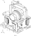
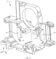
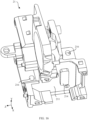
- FIG. 9 is a schematic diagram of a structure of a bracket according to an embodiment of this application.
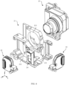
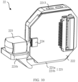
- FIG. 10 is a schematic diagram of a structure of an emission assembly according to an embodiment of this application.
- FIG. 11 is a schematic diagram of a structure of an emission assembly from another angle according to an embodiment of this application. Refer to FIG. 9 to FIG. 11 .
- an installation column 2214 is disposed on a side that is of the substrate 221 and that faces the bracket 21
- an installation hole 215 is disposed on a side that is of the bracket 21 and that faces the substrate 221
- the installation column 2214 is located in the installation hole 215, and a gap between the installation column 2214 and the installation hole 215 is filled with an adhesive.
- a connection between the installation column 2214 and the installation hole 215 may be considered as a mortise and tenon joint structure, and the adhesive is filled between the installation column 2214 and the installation hole 215, to increase adhesive bonding strength between the emission assembly 22 and the bracket 21, so that reliability of the adhesive can be further met in cases of high and low temperatures and shock vibration.
- the two installation columns 2214 may be respectively disposed on two adjacent outer sides of the hole 2211, the installation holes 215 and the installation columns 2214 are correspondingly disposed, and the two installation holes 215 may be respectively disposed on two adjacent outer sides of the installation boss 214. It should be understood that the buffer sheet 227 needs to avoid the installation column 2214.
- the substrate 221 may include a main body part 221a and a support 221b, the support 221b is connected to a side wall of the main body part 221a, a plane on which the support 221b is located is perpendicular to a plane on which the main body part 221a is located, the support 221b is located on a side that is of the main body part 221a and that faces the circuit board 222, the circuit board 222 is connected to the main body part 221a, the optical lens 223 is connected to the support 221b, the laser 224 is located at an end that is of the circuit board 222 and that is close to the optical lens 223, and the laser 224 and the optical lens 223 are disposed opposite to each other.
- the substrate 221 has two structures, that is, the main part 221a and the support 221b that are respectively used to carry the laser 224 and the optical lens 223.
- a structure of the substrate 221 is appropriately planned, so that the optical lens 223 can be aligned with the laser 224.
- the optical lenses 223 in the two emission assemblies 22 are disposed close to the mirror group 24, so that laser beams emitted by the two lasers 224 may separately pass through the optical lenses 223, converge in the mirror group 24, and then be emitted outward.
- At least one slot 2213 may be further provided in the substrate 221, to reduce a heat conduction area of the substrate 221 and to reduce heat backflow effect.
- the slot 2213 may be provided on a side wall of the main part 221a.
- a quantity and a shape of the slot 2213 are not specifically limited in this embodiment of this application. For example, there are two slots 2213 in the figure.
- FIG. 12 is a schematic top view of a lidar according to an embodiment of this application.
- the optical machine 12 and the scanner 13 may be separately fastened to the housing 11, and a laser beam emitted by the optical machine 12 may be illuminated on a reflective surface of a rotation mirror in the scanner 13 and then be reflected.
- FIG. 13 is a schematic diagram of an operating principle of a lidar according to an embodiment of this application.
- the laser beam emitted by the optical machine 12 is reflected by a rotation mirror 131 and then reflected to a side away from the optical machine 12 (as shown by solid line arrows in the figure).
- This scene is a scene in which a field of view is +70 degrees.
- the laser beam emitted by the optical machine 12 is reflected by a rotation mirror 131 and then reflected to a side close to the optical machine 12 (as shown by dashed line arrows in the figure).
- This scene is a scene in which a field of view is -70 degrees.
- the laser beam emitted by the optical machine 12 may not be reflected by the rotation mirror 131, that is, a light leakage phenomenon exists, and a field of view range of the lidar is affected.
- a requirement for size precision between the optical machine 12 and the scanner 13 is high.
- a size of the rotation mirror 131 is usually limited by an overall size of a product, and cannot be increased.
- a projection size of the rotation mirror 131 on an optical path is reduced, and is basically equal to a size of a spot. There is no size margin on two sides. Therefore, the spot of the optical machine 12 and the rotation mirror 131 need to be completely aligned. A higher degree of alignment indicates that the lidar can achieve a larger FOV
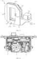
- FIG. 14 is a schematic diagram of a simplified structure of a lidar according to an embodiment of this application.
- pins 111 and kidney-shaped holes 216 are disposed to implement cooperation between the optical machine 12 and the housing 11.
- a length extension direction of the kidney-shaped hole 216 is perpendicular to a direction of the light output axis of the optical machine 12, so that a location of the optical machine 12 relative to the housing 11 can be matched.
- the location of the optical machine 12 can be fine adjusted in a direction perpendicular to the light output axis, so that the location of the optical machine 12 can be adjusted when assembled on the housing 11 (an adjustment direction of the optical machine 12 is shown by an arrow in the figure). This helps improve location precision between the optical machine 12 and the rotation mirror 131.
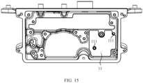
- FIG. 15 is a top view of a housing according to an embodiment of this application.
- FIG. 16 is a schematic diagram of a structure of a bracket from another angle according to an embodiment of this application.
- FIG. 17 is a bottom view of a bracket according to an embodiment of this application. Refer to FIG. 15 to FIG. 17 .
- the pins 111 may be disposed on the housing 11, the kidney-shaped holes 216 may be provided in the bracket 21, a length direction of the kidney-shaped hole 216 is perpendicular to the light output axis of the optical machine 12, the pin 111 may be installed in the kidney-shaped hole 216, and a location of the pin 111 in the kidney-shaped hole 216 can be adjusted.
- kidney-shaped holes 216 there are at least two kidney-shaped holes 216, and the two kidney-shaped holes 216 may be spaced on a bottom wall of the bracket 21, so that the optical machine 12 is limited to move only in a length direction of the kidney-shaped holes 216 to be fine adjusted in location without rotation. This ensures reliability of location adjustment.
- kidney-shaped holes 216 may be provided in the housing 11, and the pins 111 may be disposed on the bracket 21, so that a function of adjusting the location of the optical machine 12 relative to the housing 11 can also be implemented.
- the optical lens and the laser are fastened to the same substrate, and the temperature control device is used to actively control the temperature of the laser, so that the operating temperature of the laser can be accurately controlled not to exceed the standard. This avoids the impact of the temperature on the laser wavelength. In addition, the deviation of size precision between the laser and the optical lens at high and low temperatures can be avoided, so that optical performance of the lidar can be improved.
- the buffer sheet and a fitting structure of the installation column and the installation hole are disposed. This can improve adhesive bonding strength of the emission assembly and the bracket, avoid that the adhesive cracks at high and low temperatures and under shock vibration, and improve bonding reliability.
- the kidney-shaped holes are designed in the bracket to match the pins designed on the housing, so that the location of the optical machine relative to the housing can be adjusted in one direction and fastened. This implements precise alignment of a relative location of the optical machine and the scanner, and the large field of view is achieved.
- the temperature control device 225 is disposed, so that the temperature of the laser 224 can be constantly controlled at 75 ⁇ 5°C at an external ambient temperature of -40°C to +85°C.
- the laser 224 and the optical lens 223 are integrated on the same substrate 221, and the substrate 221 is disposed to be made of a material with a low coefficient of thermal expansion, so that a size deviation between the laser 224 and the optical lens 223 can be controlled to be less than 5 microns at the external ambient temperature of -40°C to +85°C.
- the location of the optical machine 12 is set to be adjustable, so that performance of a large field of view of 140 degrees can be achieved.
- An embodiment of this application provides a vehicle.
- the lidar provided in the foregoing embodiments of this application can reduce impact of a temperature on performance of the lidar, and provide performance of a large field of view. This helps improve performance such as ranging of the vehicle, and facilitates intelligence of the vehicle.
Landscapes
- Engineering & Computer Science (AREA)
- Physics & Mathematics (AREA)
- Computer Networks & Wireless Communication (AREA)
- General Physics & Mathematics (AREA)
- Radar, Positioning & Navigation (AREA)
- Remote Sensing (AREA)
- Electromagnetism (AREA)
- Optical Radar Systems And Details Thereof (AREA)
Abstract
Description
- This application claims priority to
Chinese Patent Application No. 202111679281.4, filed with the China National Intellectual Property Administration on December 31, 2021 - This application relates to the field of radar technologies, and in particular, to a lidar and a vehicle.
- A lidar (Light Detection and Ranging, Lidar) is a radar system that emits a laser beam to detect characteristics such as a location, a speed, and the like of a target. An operating principle of the lidar is to transmit a detection signal (a laser beam) to the target, then compare a received signal (a target echo) reflected from the target with the transmitted signal, and perform appropriate processing to obtain related information about the target, such as a parameter including a target distance, an orientation, a height, a speed, a posture, even a shape, and the like, to detect, track, and identify the target.
- In a conventional technology, the lidar may include a laser and a photodetector. The laser may convert an electrical pulse into an optical pulse and transmit the optical pulse, and the photodetector restores, to an electrical pulse, an optical pulse reflected from the target.
- However, in the conventional technology, no temperature control apparatus for cooling or heating the laser is disposed. A wavelength of a laser beam output by the laser is affected by a temperature of the laser. The corresponding photodetector has a specific requirement for a wavelength range of a received laser beam. If a temperature deviation of the laser is excessively large, a wavelength deviation of the laser beam is excessively large, and some laser energy exceeds a receivable wavelength range of the photodetector. This affects performance of the lidar.
- Embodiments of this application provide a lidar and a vehicle, to resolve a temperature control problem of a laser.
- An aspect of embodiments of this application provides a lidar, including a bracket and an emission assembly. The emission assembly includes a substrate, a circuit board, an optical lens, a laser, and a temperature control device, the substrate is connected to the bracket, the optical lens and the circuit board are separately connected to a side that is of the substrate and that backs onto the bracket, the laser is connected to a side that is of the circuit board and that backs onto the substrate, the temperature control device is connected to a side that is of the circuit board and that faces the substrate, a hole is disposed in the substrate, the temperature control device and the bracket are connected to each other in the hole, and a thermal gel is disposed between the temperature control device and the bracket. In this embodiment of this application, the laser is fastened to the circuit board, components of the laser and the circuit board are fastened to the substrate, and the optical lens is fastened to the substrate, so that the laser and the optical lens that are most sensitive to precision are finally fastened to a same module, that is, the substrate. This can avoid that thermal expansion and cold contraction effect caused by a temperature change affects size precision between the laser and the optical lens. In addition, the temperature control device is disposed to implement active temperature control, so that a temperature control problem of the laser can be resolved, and impact of a temperature on a wavelength of a laser beam emitted by the laser is avoided.
- In a possible implementation, the substrate includes a main body part and a support, the support is connected to a side wall of the main body part, a plane on which the support is located is perpendicular to a plane on which the main body part is located, the support is located on a side that is of the main body part and that faces the circuit board, the circuit board is connected to the main body part, the optical lens is connected to the support, the laser is located at an end that is of the circuit board and that is close to the optical lens, and the laser and the optical lens are disposed opposite to each other. The substrate has two parts of structures, respectively configured to carry the laser and the optical lens. On a basis that the laser and the optical lens are integrated on the same substrate, the optical lens can be aligned with the laser. Space utilization is appropriate.
- In a possible implementation, the temperature control device is a thermo electric cooler, and the thermo electric cooler is configured to heat or cool the circuit board. The thermo electric cooler can raise a temperature of the laser when an external ambient temperature is low, and lower the temperature of the laser when the external ambient temperature is high. In this way, the temperature of the laser is in a constant range, and the impact of the temperature on the wavelength of the laser beam emitted by the laser is avoided.
- In a possible implementation, a coefficient of thermal expansion of the substrate is less than 10 PPM. The substrate is set to have a low coefficient of thermal expansion, so that a large deviation of size precision between the laser and the optical lens caused by the thermal expansion and cold contraction effect at high and low temperatures can be avoided.
- In a possible implementation, the coefficient of thermal expansion of the substrate ranges from 4 PPM to 10 PPM. The coefficient of thermal expansion of the substrate is set to range from 4 PPM to 10 PPM. This is more likely to implement, and an adhesive between the substrate and the bracket is not prone to cracking.
- In a possible implementation, an absolute value of a difference between the coefficient of thermal expansion of the substrate and a coefficient of thermal expansion of the circuit board is less than or equal to 2 PPM. When the temperature changes greatly, in spite of impact of the thermal expansion and cold contraction, because the coefficient of thermal expansion of the substrate is close to the coefficient of thermal expansion of the circuit board, a difference in impact on the substrate and the circuit board is small, and performance of the adhesive between the substrate and the circuit board can be ensured.
- In a possible implementation, the substrate is made of a material including a kovar alloy, ceramic, or glass. The kovar alloy, the ceramic, or the glass is disposed as the substrate, so that a low coefficient of thermal expansion requirement of the substrate can be met.
- In a possible implementation, the circuit board is made of a material including aluminum nitride ceramic. The aluminum nitride ceramic is disposed as the circuit board, so that a high thermal conductivity requirement and a low coefficient of thermal expansion requirement of the circuit board can be met.
- In a possible implementation, the bracket is made of a material including an aluminum alloy. The aluminum alloy is disposed as the bracket, so that a structural strength requirement and a high thermal conductivity requirement of the bracket can be met.
- In a possible implementation, each of two ends of the circuit board is fastened to the substrate by using a cushion block, and the cushion block is a part of a structure protruding from a surface of the substrate, or the cushion block is a structure independent of the substrate and is fastened to the substrate. The cushion block can reduce a contact area between the substrate and the circuit board, increase space between the substrate and the circuit board, and reduce heat backflow effect.
- In a possible implementation, both a length and a width of the cushion block are less than 3 mm. The cushion block has a small area, so that the heat backflow effect is minimized.
- In a possible implementation, the lidar further includes a buffer sheet, the buffer sheet is located between the bracket and the substrate, the buffer sheet is bonded to the bracket by using an adhesive, and the buffer sheet is welded to the substrate, or the buffer sheet is bonded to the substrate by using an adhesive. The buffer sheet can improve reliability of bonding between the substrate and the bracket. In addition, the buffer sheet can overcome a stress caused by a mismatch between the coefficient of thermal expansion of the substrate and a coefficient of thermal expansion of the bracket.
- In a possible implementation, a coefficient of thermal expansion of the buffer sheet is greater than the coefficient of thermal expansion of the substrate, and the coefficient of thermal expansion of the buffer sheet is less than the coefficient of thermal expansion of the bracket.
- In a possible implementation, an installation column is disposed on a side that is of the substrate and that faces the bracket, an installation hole is disposed on a side that is of the bracket and that faces the substrate, the installation column is located in the installation hole, and a gap between the installation column and the installation hole is filled with an adhesive. Adhesive bonding between the installation column and the installation hole can increase adhesive bonding strength between the substrate and the bracket, so that reliability of the adhesive can be further met in cases of high and low temperatures and shock vibration.
- In a possible implementation, the lidar includes an optical machine, the optical machine includes the bracket, the emission assembly, and a receiving assembly, and the receiving assembly and the emission assembly are separately fastened to the bracket. The bracket is configured to install the emission assembly and the receiving assembly, so that optical precision machines in the lidar are integrated together to improve integration of a structure.
- In a possible implementation, the lidar further includes a housing and a scanner, both the optical machine and the scanner are installed on the housing, and a light output axis of the optical machine is aligned with a rotation mirror of the scanner. A laser beam emitted by the optical machine is reflected by the rotation mirror, and the optical machine is aligned with the rotation mirror, to ensure that all the laser beams emitted by the optical machine are reflected by the rotation mirror. This ensures a field of view range of the lidar.
- In a possible implementation, a pin is disposed on the housing, a kidney-shaped hole is provided in the bracket, a length direction of the kidney-shaped hole is perpendicular to the light output axis, the pin is installed in the kidney-shaped hole, and a location of the pin in the kidney-shaped hole can be adjusted. The location of the optical machine can be adjusted when assembled on the housing. This helps improve location precision between the optical machine and the rotation mirror, so that the lidar can achieve a larger FOV
- In a possible implementation, the optical lens is bonded to the substrate by using an adhesive, and the circuit board is bonded to the substrate by using an adhesive. The optical lens and the circuit board are separately bonded to the substrate by using an adhesive, so that fastening reliability can be ensured.
- In a possible implementation, at least one slot is provided on a side wall of the substrate. The slot is disposed to reduce a thermal conduction area of the substrate and to reduce the heat backflow effect.
- Another aspect of embodiments of this application provides a vehicle, including a vehicle body and the foregoing lidar. The lidar is fastened to the vehicle body.
- An embodiment of this application provides a vehicle. The lidar provided in the foregoing embodiments of this application can reduce impact of the temperature on performance of the lidar, and provide performance of a large field of view. This helps improve performance such as ranging of the vehicle, and facilitates intelligence of the vehicle.
- An embodiment of this application provides a lidar and a vehicle. The laser is fastened to a circuit board, components of the laser and the circuit board and an optical lens are fastened to a same substrate, and a temperature control device is used to actively control a temperature of the laser, so that an operating temperature of the laser can be accurately controlled not to exceed a standard. This avoids impact of the temperature on a laser wavelength. In addition, a deviation of size precision between the laser and the optical lens at high and low temperatures can be avoided, so that optical performance of the lidar can be improved. In addition, a buffer sheet and a fitting structure of an installation column and an installation hole are disposed. This can improve adhesive bonding strength of an emission assembly and a bracket, avoid that an adhesive cracks at high and low temperatures and under shock vibration, and improve bonding reliability. A kidney-shaped hole is designed in the bracket to match a pin designed on a housing, so that a location of an optical machine relative to the housing can be adjusted in one direction and fastened. This implements precise alignment of a relative location of the optical machine and a scanner, and a large field of view is achieved.
- For the lidar provided in embodiments of this application, the temperature control device is disposed, so that the temperature of the laser can be constantly controlled at 75±5°C at an external ambient temperature of -40°C to +85°C. The laser and the optical lens are integrated on the same substrate, and the substrate is disposed to be made of a material with a low coefficient of thermal expansion, so that a size deviation between the laser and the optical lens can be controlled to be less than 5 microns at the external ambient temperature of -40°C to +85°C. In addition, in high and low temperature and vibration tests, reliability of bonding between the emission assembly and the bracket meets a design requirement. The location of the optical machine is set to be adjustable, so that performance of a large field of view of 140 degrees can be achieved.
-
-
FIG. 1 is a schematic diagram of a structure of a vehicle according to an embodiment of this application; -
FIG. 2 is a schematic diagram of a detection range of a lidar on a vehicle according to an embodiment of this application; -
FIG. 3 is a schematic diagram of an external structure of a lidar according to an embodiment of this application; -
FIG. 4 is a schematic diagram of an internal structure of a lidar according to an embodiment of this application; -
FIG. 5 is a schematic diagram of a structure of an optical machine according to an embodiment of this application; -
FIG. 6 is a schematic exploded view of an optical machine according to an embodiment of this application; -
FIG. 7 is a schematic diagram of a simplified structure of an emission assembly and a bracket according to an embodiment of this application; -
FIG. 8 is a schematic diagram of a heat dissipation path of an emission assembly according to an embodiment of this application. -
FIG. 9 is a schematic diagram of a structure of a bracket according to an embodiment of this application; -
FIG. 10 is a schematic diagram of a structure of an emission assembly according to an embodiment of this application; -
FIG. 11 is a schematic diagram of a structure of an emission assembly from another angle according to an embodiment of this application; -
FIG. 12 is a schematic top view of a lidar according to an embodiment of this application; -
FIG. 13 is a schematic diagram of an operating principle of a lidar according to an embodiment of this application; -
FIG. 14 is a schematic diagram of a simplified structure of a lidar according to an embodiment of this application; -
FIG. 15 is a top view of a housing according to an embodiment of this application; -
FIG. 16 is a schematic diagram of a structure of a bracket from another angle according to an embodiment of this application; and -
FIG. 17 is a bottom view of a bracket according to an embodiment of this application. - Descriptions of reference numerals:
- 100-lidar; 11-housing; 111-pin; 12-optical machine; 13-scanner; 131-rotation mirror;
- 21-bracket; 211-first accommodation cavity; 212-second accommodation cavity; 213-third accommodation cavity; 214-installation boss; 215-installation hole; 216-kidney-shaped hole;
- 22-emission assembly; 221-substrate; 221a-main body part; 221b-support; 2211-hole; 2212-cushion block; 2213 -slot; 2214-installation column; 222-circuit board; 223-optical lens; 224-laser; 225-temperature control device; 226-thermal gel; 227-buffer sheet; 2281-first adhesive; 2282-second adhesive; 2283-third adhesive;
- 23-receiving assembly; 24-mirror group.
- A lidar is a radar system that emits a laser beam to detect characteristics such as a location, a speed, and the like of a target, has advantages such as high resolution, good concealment, a strong anti-active interference capability, a small size, and the like, and is widely used in fields such as resource exploration, traffic communication, environment monitoring, and the like.
- The lidar may be mounted on a vehicle as an important part of an intelligent driving environment sensing system. The vehicle-mounted lidar has advantages such as accurate acquisition of three-dimensional information of the target, high resolution, a strong anti-interference capability, a wide detection range, near-all-weather operation, and the like.
-
FIG. 1 is a schematic diagram of a structure of a vehicle according to an embodiment of this application. Refer toFIG. 1 . An aspect of embodiments of this application provides a vehicle. The vehicle includes a vehicle body and alidar 100 mounted on the vehicle body. There may be one or more lidars 100. For a location at which thelidar 100 is mounted on the vehicle body, refer to the figure. For example, thelidar 100 may be mounted at a location such as front, left front, right front, rear, or the like of the vehicle body, to detect a larger coverage area and to improve driving environment safety of the vehicle. -
FIG. 2 is a schematic diagram of a detection range of a lidar on a vehicle according to an embodiment of this application. Refer toFIG. 2 . An example in which thelidar 100 is disposed at three locations of a front, a left front, and a right front of the vehicle body is used. A detection field of view of thelidar 100 is an FOV A larger FOV indicates a larger coverage area that can be detected. That is, the FOV is a key performance parameter of thelidar 100. - In addition, an optical machine is a key core component of the vehicle-mounted lidar, and needs to output a stable high-quality laser beam and accurately receive a reflected laser beam within an entire life cycle of the vehicle. The optical machine may include an emission assembly and a receiving assembly. The emission assembly is configured to output a laser wavelength, the receiving assembly is configured to receive a laser beam reflected from a target, and a core component of the emission assembly is a laser.
- Currently, there are many difficulties in structural design of the lidar. The wavelength of the laser beam output by the laser is affected by a temperature of the laser, and the corresponding receiving assembly also has a specific requirement for a wavelength range of a received laser beam. If a temperature deviation of the laser is excessively large, a wavelength deviation of the laser beam is excessively large, and some laser energy exceeds a receivable wavelength range of the receiving assembly. This affects receiving efficiency and further affects a performance indicator of a detection distance. Therefore, how to perform temperature control design of the laser is one of the difficulties in the structural design of the lidar.
- In a conventional technology, a mainstream laser of the lidar is an edge emitting laser (Edge Emitting Laser, EEL). The EEL has advantages such as a high peak optical power, high energy efficiency, and the like, and is a preferred light source of a long-distance vehicle-mounted lidar product. How to control a temperature of the optical machine using the EEL is also a currently key challenge in structural design of the optical machine of the lidar.
- In addition, the waveform of the laser beam directly output by the laser generally does not meet a condition for direct use of the lidar, and an optical lens needs to be used for beam shaping. However, size precision between the laser and the optical lens affects laser quality. Based on an optical design requirement, the size precision between the laser and the optical lens needs to be maintained at a micron level in an entire life cycle. Machining precision and bonding reliability of components and parts, and impact of thermal expansion and cold contraction caused by a temperature change of the components and parts lead to change of the size precision between the laser and the optical lens. Therefore, how to implement a design of controlling size precision between the laser and the optical lens is one of challenges in a current design.
- In a conventional technology, the laser and a peripheral circuit may be installed on a thermo electric cooler (Thermo Electric Cooler, TEC), and are fastened to an outer housing of the lidar together with the optical lens. In this conventional technology, if sizes of the laser and the peripheral circuit are large, a size of the TEC needs to be increased, and a power consumption size needs to be increased. In addition, weights of the laser and the peripheral circuit are on the TEC, and in a vibration scenario, requirements for strength of the TEC and corresponding fastening strength are high. In addition, the laser is fastened to the outer housing by using the TEC, and the optical lens is directly fastened to the outer housing. Therefore, the TEC also participates in a process of locating a size between the laser and the lens. In thermal expansion and cold contraction effect caused by a temperature change, the size precision between the optical lens and the laser is further affected by the TEC. This is not conducive to shortening a size chain of a location relationship between the optical lens and the laser.
- Therefore, in this conventional technology, the laser is carried by using the thermo electric cooler. Although the TEC may be used to control the temperature of the laser, this technology is applicable only to a case in which the sizes of the laser and the peripheral circuit are small, for example, in a scenario in which an optical fiber laser, an optical module, or the like is used, and cannot be applicable to a scenario in which a large-sized lidar using an EEL laser is used.
- Based on the foregoing problem, an embodiment of this application provides a lidar. An optical lens and a laser are fastened to a same substrate, and a temperature control device is used to actively control a temperature of the laser, so that impact of the temperature on the laser wavelength is avoided. In addition, size precision between the laser and the optical lens can be reduced, and optical performance of the lidar can be improved.
-
FIG. 3 is a schematic diagram of an external structure of the lidar according to an embodiment of this application.FIG. 4 is a schematic diagram of an internal structure of the lidar according to an embodiment of this application. Refer toFIG. 3 and FIG. 4 . Thelidar 100 provided in this embodiment of this application may include ahousing 11, and anoptical machine 12 and ascanner 13 that are disposed inside thehousing 11. - A structure of the
housing 11 is not specifically limited in this embodiment of this application. For example, thehousing 11 may include an upper housing and a lower housing (not marked in the figure). The upper housing and the lower housing may be fastened in a manner of bonding, screw connection, or the like, to form accommodating space for accommodating theoptical machine 12 and thescanner 13. - The
optical machine 12 and thescanner 13 may be separately fastened to thehousing 11, for example, may be fastened to a bottom wall of the lower housing (in the figure, a positive direction of a Y-axis is an upper direction, and a negative direction is a lower direction). Theoptical machine 12 is configured to emit and receive a laser beam. A rotation mirror is disposed in thescanner 13. The laser beam emitted by theoptical machine 12 may be illuminated on a reflective surface of the rotation mirror and then be reflected. A light output axis of theoptical machine 12 may be aligned with the rotation mirror of thescanner 13. For example, theoptical machine 12 and thescanner 13 may be spaced on a Z-axis, and the light output axis of theoptical machine 12 may extend in a Z direction in the figure. - In addition, an information processing system (not marked in the figure) is further disposed inside the
housing 11. The information processing system is configured to process a laser signal received by theoptical machine 12. Another component is further disposed inside thehousing 11. Details are not described herein. It should be understood that theoptical machine 12 is configured to output a stable high-quality laser beam and can accurately receive a reflected laser beam, and is a key core component of thelidar 100. -
FIG. 5 is a schematic diagram of a structure of an optical machine according to an embodiment of this application.FIG. 6 is a schematic exploded view of an optical machine according to an embodiment of this application. Refer toFIG. 5 andFIG. 6 . In this embodiment of this application, anoptical machine 12 may include abracket 21,emission assemblies 22, and a receivingassembly 23. The receivingassembly 23 and theemission assemblies 22 may be separately fastened to thebracket 21. - The
bracket 21 may include afirst accommodation cavity 211, asecond accommodation cavity 212, and athird accommodation cavity 213. Thefirst accommodation cavity 211 and thesecond accommodation cavity 212 are respectively configured to accommodate theemission assemblies 22, and thethird accommodation cavity 213 is configured to accommodate the receivingassembly 23. Structures of the twoemission assemblies 22 are mirror-symmetric, structures of thefirst accommodation cavity 211 and thesecond accommodation cavity 212 are mirror-symmetric, and thefirst accommodation cavity 211 and thesecond accommodation cavity 212 may be respectively disposed on two adjacent side surfaces of thebracket 21. For example, an opening direction of thefirst accommodation cavity 211 is a positive direction of an X-axis, and an opening direction of thesecond accommodation cavity 212 is a positive direction of a Z-axis. Thethird accommodation cavity 213 is located above thefirst accommodation cavity 211 and thesecond accommodation cavity 212, and is disposed as a structure of a ring-shaped through hole. The receivingassembly 23 is disposed in the ring-shaped through hole in a penetrating manner. Specific structures of thethird accommodation cavity 213 and the receivingassembly 23 are not specifically described in this application. - The
optical machine 12 may further include amirror group 24. Themirror group 24 may be connected to thebracket 21, and is located between thefirst accommodation cavity 211 and thesecond accommodation cavity 212. Laser beams emitted by the twoemission assemblies 22 may enter themirror group 24, converge in themirror group 24, and then are emitted outward. -
FIG. 7 is a schematic diagram of a simplified structure of an emission assembly and a bracket according to an embodiment of this application. It should be understood thatFIG. 7 shows a part of a structure of thebracket 21, that is, a sectional view corresponding to oneemission assembly 22. Refer toFIG. 7 . In this embodiment of this application, theemission assembly 22 may include asubstrate 221, acircuit board 222, anoptical lens 223, alaser 224, and atemperature control device 225. - The
substrate 221 may be connected to thebracket 21, theoptical lens 223 and thecircuit board 222 may be separately connected to a side that is of thesubstrate 221 and that backs onto thebracket 21, thelaser 224 may be connected to a side that is of thecircuit board 222 and that backs onto thesubstrate 221, thetemperature control device 225 may be connected to a side that is of thecircuit board 222 and that faces thesubstrate 221, ahole 2211 is disposed in thesubstrate 221, thetemperature control device 225 and thebracket 21 are connected to each other in thehole 2211, and athermal gel 226 is disposed between thetemperature control device 225 and thebracket 21. - A vertical direction in the figure is used as an example. The
laser 224 may be welded above thecircuit board 222, thecircuit board 222 may be bonded to thesubstrate 221 by using a first adhesive 2281, theoptical lens 223 may be bonded to thesubstrate 221 by using a second adhesive 2282, and thesubstrate 221 may be bonded to thebracket 21 by using a third adhesive 2283. Thelaser 224 may be disposed at an end that is of thecircuit board 222 and that is close to theoptical lens 223, so that thelaser 224 and theoptical lens 223 are disposed close and opposite to each other. - In a possible implementation, the
lidar 100 may further include abuffer sheet 227. Thebuffer sheet 227 is located between thebracket 21 and thesubstrate 221. Thebuffer sheet 227 may be welded to thesubstrate 221, or thebuffer sheet 227 may be bonded to thesubstrate 221 by using an adhesive, and thebuffer sheet 227 may be bonded to thebracket 21 by using the third adhesive 2283. - A specific form of the
optical lens 223 is not specifically limited in this embodiment of this application. For example, theoptical lens 223 may be in a form of a double convex thick aspheric lens, and is configured to collimate diverged light emitted by thelaser 224. Thelaser 224 may be an edge emitting laser (Edge Emitting Laser, EEL), for example, may be a four-channel or an eight-channel laser. - The
temperature control device 225 is connected to thebracket 21. Thetemperature control device 225 is a device for temperature control, and may be configured to heat thelaser 224 when an external ambient temperature is low or cool thelaser 224 when an external ambient temperature is high, so that a temperature of thelaser 224 is in a constant range. This avoids impact of a temperature on a wavelength of a laser beam emitted by thelaser 224. A specific type of thetemperature control device 225 is not specifically limited in this embodiment of this application. Thetemperature control device 225 may be a thermo electric cooler TEC, and may be controlled to cool or heat thecircuit board 222 and thelaser 224 by switching positive and negative electrodes of the thermo electric cooler. - It should be understood that a location in which the
temperature control device 225 is connected to thesubstrate 221 may be maximumly close to thelaser 224, to improve heat transfer efficiency. Ahole 2211 is disposed in thesubstrate 221, so that thetemperature control device 225 may be connected to thebracket 21 in thehole 2211, to smoothly transfer heat to thebracket 21. - The
temperature control device 225 is connected to thebracket 21, to transfer heat to thebracket 21. Thetemperature control device 225 may transfer the heat to thebracket 21 by using thethermal gel 226, to improve heat dissipation efficiency. For example, a thickness of thethermal gel 226 may be less than 1.5 mm, and a thermal conductivity coefficient of thethermal gel 226 may be 5 W/m·K to 15 W/m·K. - The
bracket 21 is configured to fasten and install thesubstrate 221, to implement heat dissipation for thelaser 224. Thebracket 21 may be made of a metal such as an aluminum alloy through die casting or through machining an aluminum profile. A coefficient of thermal expansion of a manufacturing material of thebracket 21 may range from 21 PPM to 24 PPM, for example, may be approximately 23 PPM. A thermal conductivity coefficient of thebracket 21 may range from 140 W/m·K to 200 W/m·K. - The
substrate 221 is configured to carry theoptical lens 223 and thelaser 224, and may be made of a material with a low coefficient of thermal expansion (Coefficient of thermal expansion, CTE) and a low thermal conductivity coefficient. A coefficient of thermal expansion of thesubstrate 221 is less than a coefficient of thermal expansion of thebracket 21, and the coefficient of thermal expansion of thesubstrate 221 may be less than or equal to 10 PPM. - A coefficient of thermal expansion of the
buffer sheet 227 may be greater than the coefficient of thermal expansion of thesubstrate 221, and is less than the coefficient of thermal expansion of thebracket 21. For example, the coefficient of thermal expansion of thebuffer sheet 227 may range from 5 PPM to 23 PPM. Thebuffer sheet 227 can improve reliability of bonding between thesubstrate 221 and thebracket 21. The coefficient of thermal expansion of thebuffer sheet 227 is set to be between the coefficients of thermal expansion of thesubstrate 221 and thebracket 21, so that a stress caused by a mismatch between the coefficients of thermal expansion can be overcome. A material of thebuffer sheet 227 is not specifically limited in this embodiment of this application. Thebuffer sheet 227 may be made of a material such as stainless steel, aluminum, or the like, and a thickness of thebuffer sheet 227 may range from 0.2 mm to 2.0 mm. - It should be understood that it is difficult to select a material whose coefficient of thermal expansion is less than 4 PPM as the
substrate 221, and if the coefficient of thermal expansion of thesubstrate 221 is excessively small, the third adhesive 2283 between thebuffer sheet 227 and thebracket 21 is prone to cracking. For example, the coefficient of thermal expansion of thesubstrate 221 may range from 4 PPM to 10 PPM. This is more likely to implement, and the third adhesive 2283 is not prone to cracking. The thermal conductivity coefficient of thesubstrate 221 is less than 50 W/m K. - A manufacturing material of the
substrate 221 includes but is not limited to a kovar alloy, ceramic (such as aluminum oxide, zirconia, or the like), glass, and the like. In a possible implementation, thesubstrate 221 may be a kovar alloy whose coefficient of thermal expansion is approximately 5.5 PPM, for example, may be a kovar alloy whose grade is 4J29 and whose coefficient of thermal expansion is 5.5 PPM. - In addition, an absolute value of a difference between the coefficient of thermal expansion of the
substrate 221 and a coefficient of thermal expansion of thecircuit board 222 is less than or equal to 2 PPM. Thecircuit board 222 may be made of a plate material with a high thermal conductivity coefficient, for example, aluminum nitride ceramic. For example, the coefficient of thermal expansion of thecircuit board 222 may range from 4 PPM to 6 PPM. - The
substrate 221 is set to have a low coefficient of thermal expansion, thesubstrate 221 is unlikely to be affected by thermal expansion and cold contraction, and size precision is more stable, so that a large deviation of size precision between thelaser 224 and theoptical lens 223 caused by thermal expansion and cold contraction effect at high and low temperatures can be avoided. Even if thesubstrate 221 is affected by the thermal expansion and cold contraction, the coefficients of thermal expansion of thesubstrate 221 and thecircuit board 222 are set to be close, and impact of a temperature on thesubstrate 221 and thecircuit board 222 are also similar, so that impact on size precision is small. In addition, performance of the second adhesive 2282 between thesubstrate 221 and thecircuit board 222 can also be ensured, and the second adhesive 2282 is not prone to cracking caused by a large deformation difference between thesubstrate 221 and thecircuit board 222. - In a possible implementation, the coefficient of thermal expansion of the
circuit board 222 may range from 4 PPM to 5 PPM, and is less than the coefficient of thermal expansion of thesubstrate 221. The coefficient of thermal expansion of thesubstrate 221 may be 5.5 PPM, and is less than the coefficient of thermal expansion of thebracket 21. The coefficient of thermal expansion of thebracket 21 may be 23 PPM. - An
installation boss 214 may be disposed on a side that is of thebracket 21 and that faces thesubstrate 221, and theinstallation boss 214 may correspond to a location of thetemperature control device 225, to reduce a distance between thetemperature control device 225 and thebracket 21, so that thetemperature control device 225 may be connected to theinstallation boss 214 by using thethermal gel 226. Theinstallation boss 214 may be a part of a structure of thebracket 21, or theinstallation boss 214 may be a structure that is independent of thebracket 21 and that is fastened to thebracket 21. -
FIG. 8 is a schematic diagram of a heat dissipation path of an emission assembly according to an embodiment of this application. Refer toFIG. 8 . For heat generated by thelaser 224 and thecircuit board 222, the heat is transferred to thebracket 21 through thetemperature control device 225 and thethermal gel 226 in a main heat dissipation path (as shown by a large arrow in the figure), and a small part of the heat flows back (as shown by small arrows in the figure), and returns to thecircuit board 222 through thebracket 21 and thesubstrate 221. - In addition, a
cushion block 2212 may be disposed on a surface that is of thesubstrate 221 and that backs onto thebracket 21, and thecircuit board 222 is fastened to thecushion block 2212. Thecushion block 2212 is configured to perform a cushion function. Thecushion block 2212 may be, for example, in a form of a boss, a bump bar, a bump point, or the like, and can reduce a contact area between thesubstrate 221 and thecircuit board 222, increase space between thesubstrate 221 and thecircuit board 222, and reduce heat backflow effect. - The
cushion block 2212 may be a part of a structure protrudingly disposed on thesubstrate 221, and is integrated with thesubstrate 221. Alternatively, thecushion block 2212 may be a heat insulation block with a low thermal conductivity coefficient, and is fastened to thesubstrate 221 in a manner of bonding or the like, to reduce heat transferred from thesubstrate 221 to thecircuit board 222. A shape of thecushion block 2212 may be a rectangle, a circle, a long strip, or the like, and a length and a width of the cushion block 221 may be less than 3 mm, to reduce an area of thecushion block 221 and to minimize the heat backflow effect. - A process of assembling the
emission assembly 22 and thebracket 21 may be as follows: First, thelaser 224 and thetemperature control device 225 are separately fastened to thecircuit board 222, then thecircuit board 222 and theoptical lens 223 are separately fastened to thesubstrate 221 by using glue, thebuffer sheet 227 is welded to thesubstrate 221, to form theemission assembly 22, then theemission assembly 22 is bonded to thebracket 21 by using glue, and thethermal gel 226 is coated between thetemperature control device 225 and thebracket 21. - Overall, in this embodiment of this application, the
laser 224 and theoptical lens 223 that are most sensitive to precision are fastened to a same module, that is, thesubstrate 221. This can avoid that thermal expansion and cold contraction effect caused by a temperature change affects size precision between thelaser 224 and theoptical lens 223. In addition, thetemperature control device 225 is disposed to implement active temperature control, and to match a design of reducing heat backflow, so that a temperature control problem of thelaser 224 can be resolved, and impact of a temperature on a wavelength of a laser beam emitted by thelaser 224 is avoided. -
FIG. 9 is a schematic diagram of a structure of a bracket according to an embodiment of this application.FIG. 10 is a schematic diagram of a structure of an emission assembly according to an embodiment of this application.FIG. 11 is a schematic diagram of a structure of an emission assembly from another angle according to an embodiment of this application. Refer toFIG. 9 to FIG. 11 . In this embodiment of this application, aninstallation column 2214 is disposed on a side that is of thesubstrate 221 and that faces thebracket 21, aninstallation hole 215 is disposed on a side that is of thebracket 21 and that faces thesubstrate 221, theinstallation column 2214 is located in theinstallation hole 215, and a gap between theinstallation column 2214 and theinstallation hole 215 is filled with an adhesive. - A connection between the
installation column 2214 and theinstallation hole 215 may be considered as a mortise and tenon joint structure, and the adhesive is filled between theinstallation column 2214 and theinstallation hole 215, to increase adhesive bonding strength between theemission assembly 22 and thebracket 21, so that reliability of the adhesive can be further met in cases of high and low temperatures and shock vibration. - For example, there may be two
installation columns 2214. The twoinstallation columns 2214 may be respectively disposed on two adjacent outer sides of thehole 2211, the installation holes 215 and theinstallation columns 2214 are correspondingly disposed, and the twoinstallation holes 215 may be respectively disposed on two adjacent outer sides of theinstallation boss 214. It should be understood that thebuffer sheet 227 needs to avoid theinstallation column 2214. - Still refer to
FIG. 10 andFIG. 11 . Thesubstrate 221 may include amain body part 221a and asupport 221b, thesupport 221b is connected to a side wall of themain body part 221a, a plane on which thesupport 221b is located is perpendicular to a plane on which themain body part 221a is located, thesupport 221b is located on a side that is of themain body part 221a and that faces thecircuit board 222, thecircuit board 222 is connected to themain body part 221a, theoptical lens 223 is connected to thesupport 221b, thelaser 224 is located at an end that is of thecircuit board 222 and that is close to theoptical lens 223, and thelaser 224 and theoptical lens 223 are disposed opposite to each other. - The
substrate 221 has two structures, that is, themain part 221a and thesupport 221b that are respectively used to carry thelaser 224 and theoptical lens 223. On a basis of integrating thelaser 224 and theoptical lens 223 on thesame substrate 221, a structure of thesubstrate 221 is appropriately planned, so that theoptical lens 223 can be aligned with thelaser 224. With reference toFIG. 5 andFIG. 6 , it can be learned that theoptical lenses 223 in the twoemission assemblies 22 are disposed close to themirror group 24, so that laser beams emitted by the twolasers 224 may separately pass through theoptical lenses 223, converge in themirror group 24, and then be emitted outward. - In addition, at least one
slot 2213 may be further provided in thesubstrate 221, to reduce a heat conduction area of thesubstrate 221 and to reduce heat backflow effect. Theslot 2213 may be provided on a side wall of themain part 221a. A quantity and a shape of theslot 2213 are not specifically limited in this embodiment of this application. For example, there are twoslots 2213 in the figure. -
FIG. 12 is a schematic top view of a lidar according to an embodiment of this application. Refer toFIG. 12 . Theoptical machine 12 and thescanner 13 may be separately fastened to thehousing 11, and a laser beam emitted by theoptical machine 12 may be illuminated on a reflective surface of a rotation mirror in thescanner 13 and then be reflected. -
FIG. 13 is a schematic diagram of an operating principle of a lidar according to an embodiment of this application. Refer toFIG. 13 , in a use process, in a scene, the laser beam emitted by theoptical machine 12 is reflected by arotation mirror 131 and then reflected to a side away from the optical machine 12 (as shown by solid line arrows in the figure). This scene is a scene in which a field of view is +70 degrees. In another scene, the laser beam emitted by theoptical machine 12 is reflected by arotation mirror 131 and then reflected to a side close to the optical machine 12 (as shown by dashed line arrows in the figure). This scene is a scene in which a field of view is -70 degrees. It should be understood that if theoptical machine 12 and therotation mirror 131 are not aligned, in a large field of view, the laser beam emitted by theoptical machine 12 may not be reflected by therotation mirror 131, that is, a light leakage phenomenon exists, and a field of view range of the lidar is affected. - Therefore, a requirement for size precision between the
optical machine 12 and thescanner 13 is high. Especially in a large FOV scene, a size of therotation mirror 131 is usually limited by an overall size of a product, and cannot be increased. A projection size of therotation mirror 131 on an optical path is reduced, and is basically equal to a size of a spot. There is no size margin on two sides. Therefore, the spot of theoptical machine 12 and therotation mirror 131 need to be completely aligned. A higher degree of alignment indicates that the lidar can achieve a larger FOV -
FIG. 14 is a schematic diagram of a simplified structure of a lidar according to an embodiment of this application. Refer toFIG. 14 . In this embodiment of this application, pins 111 and kidney-shapedholes 216 are disposed to implement cooperation between theoptical machine 12 and thehousing 11. A length extension direction of the kidney-shapedhole 216 is perpendicular to a direction of the light output axis of theoptical machine 12, so that a location of theoptical machine 12 relative to thehousing 11 can be matched. In other words, the location of theoptical machine 12 can be fine adjusted in a direction perpendicular to the light output axis, so that the location of theoptical machine 12 can be adjusted when assembled on the housing 11 (an adjustment direction of theoptical machine 12 is shown by an arrow in the figure). This helps improve location precision between theoptical machine 12 and therotation mirror 131. -
FIG. 15 is a top view of a housing according to an embodiment of this application.FIG. 16 is a schematic diagram of a structure of a bracket from another angle according to an embodiment of this application.FIG. 17 is a bottom view of a bracket according to an embodiment of this application. Refer toFIG. 15 to FIG. 17 . In a possible implementation, thepins 111 may be disposed on thehousing 11, the kidney-shapedholes 216 may be provided in thebracket 21, a length direction of the kidney-shapedhole 216 is perpendicular to the light output axis of theoptical machine 12, thepin 111 may be installed in the kidney-shapedhole 216, and a location of thepin 111 in the kidney-shapedhole 216 can be adjusted. - For example, there are at least two kidney-shaped
holes 216, and the two kidney-shapedholes 216 may be spaced on a bottom wall of thebracket 21, so that theoptical machine 12 is limited to move only in a length direction of the kidney-shapedholes 216 to be fine adjusted in location without rotation. This ensures reliability of location adjustment. - It is not difficult to understand that in another possible implementation, the kidney-shaped
holes 216 may be provided in thehousing 11, and thepins 111 may be disposed on thebracket 21, so that a function of adjusting the location of theoptical machine 12 relative to thehousing 11 can also be implemented. - For the lidar provided in the foregoing embodiments of this application, the optical lens and the laser are fastened to the same substrate, and the temperature control device is used to actively control the temperature of the laser, so that the operating temperature of the laser can be accurately controlled not to exceed the standard. This avoids the impact of the temperature on the laser wavelength. In addition, the deviation of size precision between the laser and the optical lens at high and low temperatures can be avoided, so that optical performance of the lidar can be improved.
- In addition, the buffer sheet and a fitting structure of the installation column and the installation hole are disposed. This can improve adhesive bonding strength of the emission assembly and the bracket, avoid that the adhesive cracks at high and low temperatures and under shock vibration, and improve bonding reliability. The kidney-shaped holes are designed in the bracket to match the pins designed on the housing, so that the location of the optical machine relative to the housing can be adjusted in one direction and fastened. This implements precise alignment of a relative location of the optical machine and the scanner, and the large field of view is achieved.
- Overall, for the lidar provided in the foregoing embodiments of this application, the
temperature control device 225 is disposed, so that the temperature of thelaser 224 can be constantly controlled at 75±5°C at an external ambient temperature of -40°C to +85°C. Thelaser 224 and theoptical lens 223 are integrated on thesame substrate 221, and thesubstrate 221 is disposed to be made of a material with a low coefficient of thermal expansion, so that a size deviation between thelaser 224 and theoptical lens 223 can be controlled to be less than 5 microns at the external ambient temperature of -40°C to +85°C. In addition, in high and low temperature and vibration tests, reliability of bonding between theemission assembly 22 and thebracket 21 meets a design requirement. The location of theoptical machine 12 is set to be adjustable, so that performance of a large field of view of 140 degrees can be achieved. - An embodiment of this application provides a vehicle. The lidar provided in the foregoing embodiments of this application can reduce impact of a temperature on performance of the lidar, and provide performance of a large field of view. This helps improve performance such as ranging of the vehicle, and facilitates intelligence of the vehicle.
- Finally, it should be noted that the foregoing embodiments are merely intended for describing the technical solutions in embodiments of this application, instead of limiting the technical solutions. Although embodiments of this application are described in detail with reference to the foregoing embodiments, persons of ordinary skill in the art should understand that they may still make modifications to the technical solutions described in the foregoing embodiments or make equivalent replacements to some or all technical features thereof, without departing from the scope of the technical solutions in the embodiments of this application.
Claims (20)
- A lidar, comprising a bracket and an emission assembly, wherein
the emission assembly comprises a substrate, a circuit board, an optical lens, a laser, and a temperature control device, the substrate is connected to the bracket, the optical lens and the circuit board are separately connected to a side that is of the substrate and that backs onto the bracket, the laser is connected to a side that is of the circuit board and that backs onto the substrate, the temperature control device is connected to a side that is of the circuit board and that faces the substrate, a hole is disposed in the substrate, the temperature control device and the bracket are connected to each other in the hole, and a thermal gel is disposed between the temperature control device and the bracket. - The lidar according to claim 1, wherein the substrate comprises a main body part and a support, the support is connected to a side wall of the main body part, a plane on which the support is located is perpendicular to a plane on which the main body part is located, the support is located on a side that is of the main body part and that faces the circuit board, the circuit board is connected to the main body part, the optical lens is connected to the support, the laser is located at an end that is of the circuit board and that is close to the optical lens, and the laser and the optical lens are disposed opposite to each other.
- The lidar according to claim 1 or 2, wherein the temperature control device is a thermo electric cooler, and the thermo electric cooler is configured to heat or cool the circuit board.
- The lidar according to any one of claims 1 to 3, wherein a coefficient of thermal expansion of the substrate is less than or equal to 10 PPM.
- The lidar according to claim 4, wherein the coefficient of thermal expansion of the substrate ranges from 4 PPM to 10 PPM.
- The lidar according to any one of claims 1 to 5, wherein an absolute value of a difference between the coefficient of thermal expansion of the substrate and a coefficient of thermal expansion of the circuit board is less than or equal to 2 PPM.
- The lidar according to claim 6, wherein the substrate is made of a material comprising a kovar alloy, ceramic, or glass.
- The lidar according to claim 6, wherein the circuit board is made of a material comprising aluminum nitride ceramic.
- The lidar according to any one of claims 1 to 8, wherein the bracket is made of a material comprising an aluminum alloy.
- The lidar according to any one of claims 1 to 9, wherein each of two ends of the circuit board is fastened to the substrate by using a cushion block, and the cushion block is a part of a structure protruding from a surface of the substrate, or the cushion block is a structure independent of the substrate and is fastened to the substrate.
- The lidar according to claim 10, wherein both a length and a width of the cushion block are less than 3 mm.
- The lidar according to any one of claims 1 to 11, wherein the lidar further comprises a buffer sheet, the buffer sheet is located between the bracket and the substrate, the buffer sheet is bonded to the bracket by using an adhesive, and the buffer sheet is welded to the substrate, or the buffer sheet is bonded to the substrate by using an adhesive.
- The lidar according to claim 12, wherein a coefficient of thermal expansion of the buffer sheet is greater than the coefficient of thermal expansion of the substrate, and the coefficient of thermal expansion of the buffer sheet is less than a coefficient of thermal expansion of the bracket.
- The lidar according to claim 12, wherein an installation column is disposed on a side that is of the substrate and that faces the bracket, an installation hole is disposed on a side that is of the bracket and that faces the substrate, the installation column is located in the installation hole, and a gap between the installation column and the installation hole is filled with an adhesive.
- The lidar according to any one of claims 1 to 14, wherein the lidar comprises an optical machine, the optical machine comprises the bracket, the emission assembly, and the receiving assembly, and the receiving assembly and the emission assembly are separately fastened to the bracket.
- The lidar according to claim 15, wherein the lidar further comprises a housing and a scanner, both the optical machine and the scanner are installed on the housing, and a light output axis of the optical machine is aligned with a rotation mirror of the scanner.
- The lidar according to claim 16, wherein a pin is disposed on the housing, a kidney-shaped hole is provided in the bracket, a length direction of the kidney-shaped hole is perpendicular to the light output axis, the pin is installed in the kidney-shaped hole, and a location of the pin in the kidney-shaped hole is adjustable.
- The lidar according to any one of claims 1 to 17, wherein the optical lens is bonded to the substrate by using an adhesive, and the circuit board is bonded to the substrate by using an adhesive.
- The lidar according to any one of claims 1 to 18, wherein at least one slot is provided on a side wall of the substrate.
- A vehicle, comprising a vehicle body and at least one lidar according to any one of claims 1 to 19, wherein the lidar is fastened to the vehicle body.
Applications Claiming Priority (2)
| Application Number | Priority Date | Filing Date | Title |
|---|---|---|---|
| CN202111679281.4A CN116413726A (en) | 2021-12-31 | 2021-12-31 | LiDAR and Vehicles |
| PCT/CN2022/143047 WO2023125731A1 (en) | 2021-12-31 | 2022-12-28 | Lidar and vehicle |
Publications (2)
| Publication Number | Publication Date |
|---|---|
| EP4451013A1 true EP4451013A1 (en) | 2024-10-23 |
| EP4451013A4 EP4451013A4 (en) | 2025-03-26 |
Family
ID=86998072
Family Applications (1)
| Application Number | Title | Priority Date | Filing Date |
|---|---|---|---|
| EP22914981.0A Pending EP4451013A4 (en) | 2021-12-31 | 2022-12-28 | Lidar and vehicle |
Country Status (3)
| Country | Link |
|---|---|
| EP (1) | EP4451013A4 (en) |
| CN (1) | CN116413726A (en) |
| WO (1) | WO2023125731A1 (en) |
Families Citing this family (1)
| Publication number | Priority date | Publication date | Assignee | Title |
|---|---|---|---|---|
| CN116609766B (en) * | 2023-07-21 | 2023-11-07 | 深圳市速腾聚创科技有限公司 | Laser radar and mobile device |
Family Cites Families (5)
| Publication number | Priority date | Publication date | Assignee | Title |
|---|---|---|---|---|
| WO2019010320A1 (en) * | 2017-07-05 | 2019-01-10 | Ouster, Inc. | Light ranging device with electronically scanned emitter array and synchronized sensor array |
| CN209417295U (en) * | 2018-11-13 | 2019-09-20 | 北醒(北京)光子科技有限公司 | A kind of laser radar main module and laser radar |
| WO2021001502A1 (en) * | 2019-07-03 | 2021-01-07 | Blickfeld GmbH | Post-scanner telescope optics for lidar system |
| CN214623023U (en) * | 2020-11-26 | 2021-11-05 | 上海禾赛科技股份有限公司 | Transmitting circuit board assembly, transmitting module and laser radar |
| CN113791418A (en) * | 2021-09-30 | 2021-12-14 | 北醒(北京)光子科技有限公司 | A laser ranging radar |
-
2021
- 2021-12-31 CN CN202111679281.4A patent/CN116413726A/en active Pending
-
2022
- 2022-12-28 EP EP22914981.0A patent/EP4451013A4/en active Pending
- 2022-12-28 WO PCT/CN2022/143047 patent/WO2023125731A1/en not_active Ceased
Also Published As
| Publication number | Publication date |
|---|---|
| CN116413726A (en) | 2023-07-11 |
| WO2023125731A1 (en) | 2023-07-06 |
| EP4451013A4 (en) | 2025-03-26 |
Similar Documents
| Publication | Publication Date | Title |
|---|---|---|
| US12517225B2 (en) | Laser transceiving module and light adjustment method thereof, LiDAR, and automatic drive apparatus | |
| CN208239607U (en) | A kind of laser radar radiator structure | |
| US11867820B2 (en) | Mirror adjusting device, reflecting assembly, LiDAR, and intelligent driving apparatus | |
| CN112198600A (en) | Multi-channel light receiving assembly for optical communication and optical path coupling method thereof | |
| CN218216098U (en) | Laser transmitter and laser radar | |
| US11885913B2 (en) | LiDAR and automobile | |
| WO2022006752A1 (en) | Laser receiving apparatus, laser radar, and smart sensing device | |
| US20210006036A1 (en) | Optical module | |
| CN112859258B (en) | Integrally designed laser radar bar optical fiber coupling module | |
| CN115236632A (en) | Lens module, laser module and lidar device | |
| WO2023125731A1 (en) | Lidar and vehicle | |
| EP1353421B1 (en) | Optical module with a monitor photo diode | |
| CN110596675A (en) | Laser emission device and laser radar system | |
| US20250164611A1 (en) | Optical radar device, light source structure and the assembly process thereof | |
| CN221351737U (en) | Laser radar and window assembly thereof | |
| CN113791418A (en) | A laser ranging radar | |
| JPS60221713A (en) | Photoelectric module casing | |
| CN118448976A (en) | Light source based on cylindrical mirror and preparation method thereof | |
| CN113655487B (en) | Continuous field laser short-range detection front-end device | |
| CN217112718U (en) | Lens assembly and laser radar | |
| US20220206118A1 (en) | METHODS AND APPARATUSES FOR THERMAL MANAGEMENT OF A DETECTION SENSOR ASSEMBLY IN A LiDAR SYSTEM | |
| CN223976748U (en) | Infrared temperature measurement system and equipment | |
| CN223244813U (en) | Laser radar | |
| CN219915975U (en) | Heat conduction diaphragm | |
| WO2024120387A1 (en) | Opto-mechanical component of lidar and lidar |
Legal Events
| Date | Code | Title | Description |
|---|---|---|---|
| STAA | Information on the status of an ep patent application or granted ep patent |
Free format text: STATUS: THE INTERNATIONAL PUBLICATION HAS BEEN MADE |
|
| PUAI | Public reference made under article 153(3) epc to a published international application that has entered the european phase |
Free format text: ORIGINAL CODE: 0009012 |
|
| STAA | Information on the status of an ep patent application or granted ep patent |
Free format text: STATUS: REQUEST FOR EXAMINATION WAS MADE |
|
| 17P | Request for examination filed |
Effective date: 20240715 |
|
| AK | Designated contracting states |
Kind code of ref document: A1 Designated state(s): AL AT BE BG CH CY CZ DE DK EE ES FI FR GB GR HR HU IE IS IT LI LT LU LV MC ME MK MT NL NO PL PT RO RS SE SI SK SM TR |
|
| RAP1 | Party data changed (applicant data changed or rights of an application transferred) |
Owner name: SHENZHEN YINWANG INTELLIGENTTECHNOLOGIES CO., LTD. |
|
| A4 | Supplementary search report drawn up and despatched |
Effective date: 20250224 |
|
| RIC1 | Information provided on ipc code assigned before grant |
Ipc: G01S 17/931 20200101ALI20250218BHEP Ipc: G01S 17/02 20200101ALI20250218BHEP Ipc: G01S 7/481 20060101ALI20250218BHEP Ipc: G01S 17/08 20060101AFI20250218BHEP |
|
| DAV | Request for validation of the european patent (deleted) | ||
| DAX | Request for extension of the european patent (deleted) | ||
| GRAP | Despatch of communication of intention to grant a patent |
Free format text: ORIGINAL CODE: EPIDOSNIGR1 |
|
| STAA | Information on the status of an ep patent application or granted ep patent |
Free format text: STATUS: GRANT OF PATENT IS INTENDED |
|
| INTG | Intention to grant announced |
Effective date: 20260206 |