EP4450942A1 - Shaving razor component test method - Google Patents
Shaving razor component test method Download PDFInfo
- Publication number
- EP4450942A1 EP4450942A1 EP24165921.8A EP24165921A EP4450942A1 EP 4450942 A1 EP4450942 A1 EP 4450942A1 EP 24165921 A EP24165921 A EP 24165921A EP 4450942 A1 EP4450942 A1 EP 4450942A1
- Authority
- EP
- European Patent Office
- Prior art keywords
- razor component
- clamp
- shaving razor
- rotatable clamp
- rotatable
- Prior art date
- Legal status (The legal status is an assumption and is not a legal conclusion. Google has not performed a legal analysis and makes no representation as to the accuracy of the status listed.)
- Granted
Links
Images








Classifications
-
- G—PHYSICS
- G01—MEASURING; TESTING
- G01M—TESTING STATIC OR DYNAMIC BALANCE OF MACHINES OR STRUCTURES; TESTING OF STRUCTURES OR APPARATUS, NOT OTHERWISE PROVIDED FOR
- G01M5/00—Investigating the elasticity of structures, e.g. deflection of bridges or air-craft wings
- G01M5/0041—Investigating the elasticity of structures, e.g. deflection of bridges or air-craft wings by determining deflection or stress
- G01M5/005—Investigating the elasticity of structures, e.g. deflection of bridges or air-craft wings by determining deflection or stress by means of external apparatus, e.g. test benches or portable test systems
- G01M5/0058—Investigating the elasticity of structures, e.g. deflection of bridges or air-craft wings by determining deflection or stress by means of external apparatus, e.g. test benches or portable test systems of elongated objects, e.g. pipes, masts, towers or railways
-
- B—PERFORMING OPERATIONS; TRANSPORTING
- B26—HAND CUTTING TOOLS; CUTTING; SEVERING
- B26B—HAND-HELD CUTTING TOOLS NOT OTHERWISE PROVIDED FOR
- B26B21/00—Razors of the open or knife type; Safety razors or other shaving implements of the planing type; Hair-trimming devices involving a razor-blade; Equipment therefor
- B26B21/40—Details or accessories
- B26B21/4081—Shaving methods; Usage or wear indication; Testing methods
- B26B21/4093—Testing of shaving razors or components thereof
-
- G—PHYSICS
- G01—MEASURING; TESTING
- G01M—TESTING STATIC OR DYNAMIC BALANCE OF MACHINES OR STRUCTURES; TESTING OF STRUCTURES OR APPARATUS, NOT OTHERWISE PROVIDED FOR
- G01M5/00—Investigating the elasticity of structures, e.g. deflection of bridges or air-craft wings
- G01M5/0075—Investigating the elasticity of structures, e.g. deflection of bridges or air-craft wings by means of external apparatus, e.g. test benches or portable test systems
-
- G—PHYSICS
- G01—MEASURING; TESTING
- G01M—TESTING STATIC OR DYNAMIC BALANCE OF MACHINES OR STRUCTURES; TESTING OF STRUCTURES OR APPARATUS, NOT OTHERWISE PROVIDED FOR
- G01M99/00—Subject matter not provided for in other groups of this subclass
- G01M99/007—Subject matter not provided for in other groups of this subclass by applying a load, e.g. for resistance or wear testing
-
- G—PHYSICS
- G01—MEASURING; TESTING
- G01N—INVESTIGATING OR ANALYSING MATERIALS BY DETERMINING THEIR CHEMICAL OR PHYSICAL PROPERTIES
- G01N3/00—Investigating strength properties of solid materials by application of mechanical stress
- G01N3/02—Details
- G01N3/04—Chucks
-
- G—PHYSICS
- G01—MEASURING; TESTING
- G01N—INVESTIGATING OR ANALYSING MATERIALS BY DETERMINING THEIR CHEMICAL OR PHYSICAL PROPERTIES
- G01N3/00—Investigating strength properties of solid materials by application of mechanical stress
- G01N3/22—Investigating strength properties of solid materials by application of mechanical stress by applying steady torsional forces
Definitions
- the present disclosure relates generally to methods for testing shaving razor components and more specifically to methods for testing the flexibility, strength, and/or resiliency of shaving razor components.
- Various embodiments relate to a shaving razor component test method comprising the steps of providing a rotatable clamp, providing a fixed clamp, securing a first end of a shaving razor component to the rotatable clamp, securing a second end of the shaving razor component to the fixed clamp, and rotating the rotatable clamp. The rotating may cause the shaving razor component to fail.
- a shaving razor component test method comprising the steps of providing a first rotatable clamp, providing a first fixed clamp, securing a first end of a first shaving razor component to the first rotatable clamp, securing a second end of the first shaving razor component to the first fixed clamp, providing a second rotatable clamp, providing a second fixed clamp, securing a first end of a second shaving razor component to the second rotatable clamp, securing a second end of the second shaving razor component to the second fixed clamp, and rotating the first rotatable clamp and the second rotatable clamp simultaneously.
- the rotating may cause at least one of the first shaving razor component and the second shaving razor component to fail.
- the present disclosure is not limited to particular materials, reagents, reaction materials, manufacturing processes, or the like, as such can vary. It is also to be understood that the terminology used herein is for purposes of describing particular embodiments only and is not intended to be limiting. It is also possible in the present disclosure that steps can be executed in different sequence where this is logically possible.
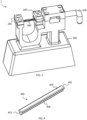
- FIG. 1, FIG. 2 , and FIG. 3 cooperate to illustrate a shaving razor component testing apparatus 1 and a function thereof.
- the razor component testing apparatus 1 may comprise a rotatable clamp 100, and a fixed clamp 200, which are both mounted to a body 300.
- the rotatable clamp 100 may be rotatably coupled to an actuator 500.
- the actuator 500 may comprise a crank handle 502 and a shaft 504 that may rotate within a frame 506.
- the frame 506 may be mounted to or integrally formed with the body 300.
- FIG. 3 shows the razor component testing apparatus 1 during a rotation of the rotatable clamp 500. When the actuator 500 is rotated, the rotatable clamp 100 may rotate and the fixed clamp 200 may remain stationary.
- the rotation may twist a shaving razor component 400 clamped between the rotatable clamp 100 and the fixed clamp 200.
- the twisting may eventually cause the shaving razor component 400 to fail.
- This test may facilitate a comparison of the flexibility, strength, and/or resiliency of shaving razor components, including, for example, components comprising different materials, such as ethyl vinyl acetate or high impact polystyrene.
- FIG. 4 is a schematic diagram providing an isometric view of a razor component 400.
- the razor component 400 may have a first end 401 and a second end 402.
- the first end 401 may be clamped in the rotatable clamp 100.
- the second end 402 may be clamped in the fixed clamp 200.
- the razor component 400 may be any type of component, including for example a component made of ethyl vinyl acetate or high impact polystyrene.
- the razor component 400 may have any shape, for example, an extended T-shape as illustrated, comprising a horizontally extending top portion 404 and a vertically extending bottom portion 406 that is perpendicular to the horizontally extending top portion 404.
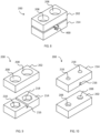
- FIG. 5, FIG. 6, and FIG. 7 cooperate to illustrate various views of a rotatable clamp 100 of a razor component testing apparatus 1.
- FIG. 5 is a schematic diagram providing an isometric view of a rotatable clamp 100 clamping a razor component 400.
- the rotatable clamp 100 may comprise a top portion 102 and a bottom portion 128.
- the top portion 102 may comprise one or more apertures 114, which may accommodate a magnet, a bolt, or a nut to secure the top portion 102 to the bottom portion 128.
- the rotatable clamp 100 may be rotatably coupled to a drive shaft 504 of an actuator 500.
- FIG. 6 is a schematic diagram providing an exploded isometric view of a rotatable clamp 100.
- the bottom portion 128 may comprise one or more apertures 132, which may accommodate a magnet, a bolt, or a nut to secure the bottom portion 128 to the top portion 102.
- the bottom portion 128 may further comprise a bottom clamp groove 130 that may be shaped to receive a shaving razor component 400 or a portion thereof, such as, for example a vertically extending bottom portion 406 of a razor component 400 having an extended T-shape (See: FIG. 4 ).
- the top portion 102 may comprise a top clamp groove which may also be shaped to receive a shaving razor component 400. Such a top clamp groove make cooperate with the bottom clamp groove 130 to receive the shaving razor component 400.
- FIG. 7 is a schematic exploded isometric bottom view of a rotatable clamp 100, showing that the aperture 132 in the bottom portion 128 may receive a nut (not shown) to engage with a bolt (not shown) or a magnet (not shown) passing through the apertures 114 of the top portion 102.
- FIG. 8, FIG. 9, and FIG. 10 cooperate to illustrate various views of a fixed clamp 100 of a razor component testing apparatus 1.
- FIG. 8 is a schematic diagram providing an isometric view of a fixed clamp 200 clamping a razor component 400.
- the fixed clamp 200 may comprise a top portion 202 and a bottom portion 214.
- the top portion 202 may comprise one or more apertures 208, which may accommodate a magnet, a bolt, or a nut to secure the top portion 202 to the bottom portion 214.
- the fixed clamp 200 or the bottom portion 214 thereof may be rigidly affixed to or integrally formed with a body 300 of a razor component testing apparatus 2 (See: FIG. 14 ).
- FIG. 9 is a schematic diagram providing an exploded isometric view of a fixed clamp 200 and FIG.
- the bottom portion 214 may comprise one or more apertures 218, which may accommodate a magnet, a bolt, or a nut to secure the bottom portion 214 to the top portion 202.
- the bottom portion 214 may further comprise a bottom clamp groove 216 that may be shaped to receive a shaving razor component 400.
- the top portion 202 may comprise a top clamp groove which may also be shaped to receive a shaving razor component 400. Such a top clamp groove may cooperate with the bottom clamp groove 216 to receive the shaving razor component 400.
- any of the apertures 114, 132, 208, 218 in the fixed clamp 100 or the rotatable clamp 200 may be configured to receive a magnet, to receive a nut (not shown), to receive a bolt (not shown) or to receive any other suitable device for generating a clamping force between the top portions 102, 202 and the corresponding bottom portions 128, 214.
- the clamping force may be in a range of about 1 N to about 30 N.
- the force may be calibrated for specific razor components 400 to avoid crushing the razor component 400 and to allow the razor component 400 to fail between the rotatable clamp 100 and the fixed clamp 200 instead of at the point where the razor component 400 is gripped by the rotatable clamp 100 or by the fixed clamp 200.
- FIG. 11, FIG. 12 , and FIG. 13 cooperate to illustrate a shaving razor component testing apparatus 2 and a function thereof.
- FIG. 11 is an isometric view of a razor component testing apparatus 2.
- the razor component testing apparatus 2 may comprise a rotatable clamp assembly 101.
- the rotatable clamp assembly 101 may comprise a first rotatable clamp 100a and a second rotatable clamp 100b.
- the razor component testing apparatus 2 may further comprise a first fixed clamp 200a and a second fixed clamp 200b.
- the rotatable clamp assembly 101 as well as the first fixed clamp 200a and the second fixed clamp 200b may be mounted to a body 300.
- the razor components 400a, 400b may have any shape, for example, an extended T-shape as illustrated, comprising a horizontally extending top portion 404a, b and a vertically extending bottom portion 406a, b that is perpendicular to the horizontally extending top portion 404.
- FIG. 12 is a schematic diagram providing an isometric view of a pair of razor components 400a, 400b.
- the first shaving razor component 400a may comprise a first end 402a and a second end 402b.
- the second shaving razor component 400b may comprise a first end 401b and a second end 402b.
- the first shaving razor component 400a may be clamped between the first rotatable clamp 100a and the first fixed clamp 200a.
- the first end 401a of the first shaving razor component 400a may be clamped in the first rotatable clamp 100a while the second end 402a of the first shaving razor component 400a may be clamped in the first fixed clamp 200a.
- the second shaving razor component 400b may be clamped between the second rotatable clamp 100b and the second fixed clamp 200b.
- the first end 401b of the second shaving razor component 400b may be clamped in the second rotatable clamp 100b while the second end 402b of the second shaving razor component 400b may be clamped in the second fixed clamp 200b.
- FIG. 13 is a schematic diagram providing an isometric view of a razor component testing apparatus 2 during a rotation of a rotatable clamp assembly 101 thereof.
- the razor component testing apparatus 2 may further comprise an actuator 500, which, as will be described hereinafter, may transfer rotational power to the rotatable clamp assembly 101 to rotate both the first rotatable clamp 100a and the second rotatable clamp 100b simultaneously.
- the first shaving razor component 400a and the second shaving razor component 400b may be twisted as shown in FIG. 13 .
- the twisting may eventually cause one of the shaving razor components 400a, 400b to fail.
- This test may facilitate a comparison of the flexibility, strength, and/or resiliency of shaving razor components, including, for example, components comprising different materials, such as ethyl vinyl acetate or high impact polystyrene.
- FIG. 14 , FIG. 15, and FIG. 16 cooperate to illustrate a body 300 of a razor component testing apparatus 2.
- FIG. 14 is a schematic diagram providing an isometric view of a body 300 of a razor component testing apparatus 2.
- FIG. 15 is a schematic diagram providing a top view of a body 300 of a razor component testing apparatus 2.
- FIG. 16 is a schematic diagram providing a cross-sectional view of the body 300 of the razor component testing apparatus 2 shown in FIG. 15 , along line A-A.
- the body 300 may define a drive belt aperture 304 through which a drive belt 510 (See: FIG. 32 ) may pass.
- the body 300 may also define an actuator shaft aperture 306 through which a drive shaft 504 may pass.
- the body 300 may further define an actuator clearance groove 308 to provide clearance for a crank handle 502 of an actuator 500 (See: FIG. 31 ).
- the body 300 may comprise a rotatable clamp support 302 to accommodate a rotatable clamp assembly 101 (See: FIG. 22 ).
- the previously mentioned bottom portion 214a of a first fixed clamp 200a and a bottom portion 214b of a second fixed clamp 200b may be integrally formed with the body 300 or otherwise affixed thereto.
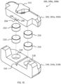
- FIG. 17, FIG. 18 , FIG. 19 , FIG. 20, and FIG. 21 cooperate to illustrate one type of fixed clamp 200, 200a, 200b that may be used in any of the razor component testing apparatuses 1, 2 described herein. It is to be appreciated that any variation of a fixed clamp 200, 200a, 200b described herein may be employed in the razor component testing apparatuses 1, 2. Variations on the fixed clamps 200, 200a, 200b may also be employed.
- FIG. 17 is a schematic diagram providing an isometric view and FIG. 18 is a schematic diagram providing a front view of fixed clamp 200, 200a, 200b of a razor component testing apparatus 1, 2.
- a fixed clamp 200, 200a, 200b may comprise a top portion 202, 202a, 202b, and a bottom portion 214, 214a, 214b.
- the top portion 202, 202a, 202b may comprise a top clamp groove 204.
- One or more gripping teeth 206 may be defined within the top clamp groove 204.
- the top portion 202, 202a, 202b may also include a grip 212 to allow a user to handle the top portion 202, 202a, 202b more easily.
- the grip 212 may, for example, facilitate the attachment or detachment of the top portion 202, 202a, 202b to or from the bottom portion 214, 214a, 214b.
- the bottom portion 214, 214a, 214b may comprise a bottom clamp groove 216.
- the top clamp groove 204 and the bottom clamp groove 216 may be a pair of cooperating grooves shaped to receive a first end 401, 401a, 401b or a second end 402, 402a, 402b of a shaving razor component 400, 400a, 400b (See: FIG. 4 or FIG. 12 ).
- the one or more gripping teeth 206 may be positioned within the pair of cooperating grooves 204, 216 to press against or to penetrate a horizontally extending top portion 404 of a razor component 400 that has an extended T-shape (See: FIG. 4 , and FIG. 12 ).
- FIG. 19 is a schematic diagram providing an exploded view of fixed clamp 200, 200a, 200b of a razor component testing apparatus 1, 2.
- the bottom portion 214, 214a, 214b may comprise one or more apertures 218, which may accommodate a magnet 210, a bolt, or a nut.
- FIG. 20 is a schematic exploded bottom view of a top portion 202, 202a, 202b of a fixed clamp 200, 200a, 200b of a razor component testing apparatus 1, 2.
- the top portion 202, 202a, 202b may comprise one or more apertures 208, which may accommodate a magnet 210, a bolt, or a nut.
- Cooperation of the magnets 210 or other suitable devices may generate a clamping force between the top portion 202, 202a, 202b and the corresponding bottom portion 214, 214a, 214b.
- the clamping force may be in a range of about 1 N to about 30 N.
- FIG. 21 is a schematic diagram providing an isometric view of a fixed clamp 200, 200a, 200b of a razor component testing apparatus clamping a razor component 1,2. As shown, the one or more gripping teeth 206 may press against the horizontally extending top portion 404 of the extended T-shaped razor component 400.
- the number and positioning of the gripping teeth 206 may be calibrated along with the clamping force for specific razor component(s) 400, 400a, 400b to avoid crushing the razor component 400, 400a, 400b and to allow the razor component(s) 400, 400a, 400b to fail between the rotatable clamp 100, 100a, 100b and the corresponding fixed clamp 200, 200a, 200b instead of at the point where the razor component(s) 400 is/are gripped by the rotatable clamp(s) 100, 100a, 100b or by the fixed clamp(s) 200, 200a, 200b.
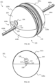
- FIG. 22, FIG. 23 , FIG. 24 , FIG. 25 , FIG. 26, FIG. 27 , FIG. 28, FIG. 29 , FIG. 30 , and FIG. 31 cooperate to illustrate a rotatable clamp assembly 101 and various components thereof.
- the rotatable clamp assembly may comprise a first rotatable clamp 100a and a second rotatable clamp 100b.
- These rotatable clamps 100a, 100b exemplify one type of rotatable clamp 100, 100a, 100b that may be used in any of the razor component testing apparatuses 1, 2 described herein. It is to be appreciated that any variation of a rotatable clamp 100, 100a, 100b described herein may be employed in the razor component testing apparatuses 1, 2. Variations on the rotatable clamps 100, 100a, 100b may also be employed.
- FIG. 22 is a schematic diagram providing an isometric view and FIG. 23 is a schematic diagram providing a side view of a rotatable clamp assembly 101 comprising a first rotatable clamp 100a clamping a first razor component 400a and a second rotatable clamp 100b clamping a second razor component 400b.
- the first rotatable clamp 100a may comprise a top portion 102a and a bottom portion 128a.
- the second rotatable clamp 100b may comprise a top portion 102b and a bottom portion 128b. It is to be appreciated that the top portions 102a, 102b and the bottom portions 128a, 128b of the first rotatable clamp 100a and the second rotatable clamp 100b may have the same or similar features.
- the top portions 102a, 102b may comprise an outer surface 104.
- the outer surface 104 may comprise a gripping tool aperture 106 to allow a tool (not shown) to be inserted into the top portion 102b to make it easier for a user to detach the top portion 102a, 102b from the base assembly 126.
- the bottom portions 128a, 128b maybe affixed to or integral with a base assembly 126, such that the base assembly 126 may comprise both bottom portions 128a, 128b.
- the base assembly 126 may define a rotation groove 138, which may be rotatably coupled to a rotatable clamp support 302 of their body 300 of a razor component testing apparatus 2 (See: FIGs. 14 - 16 ).
- the top portions 102a, 102b may comprise a top clamp groove 110.
- One or more gripping teeth 112 may be defined within the top clamp groove 110.
- the bottom portions 128a, 128b may comprise a bottom clamp groove 130.
- the top clamp groove 110 and the bottom clamp groove 130 may be a pair of cooperating grooves shaped to receive a first end 401, 401a, 401b or a second end 402, 402a, 402b of a shaving razor component 400, 400a, 400b (See: FIG. 4 or FIG. 12 ).
- the one or more gripping teeth 112 may be positioned within the pair of cooperating grooves 110, 130 to press against or to penetrate a horizontally extending top portion 404 of a razor component 400 that has an extended T-shape (See: FIG. 4 , and FIG. 12 ).
- the number and positioning of the gripping teeth 112 may be calibrated along with the clamping force for specific razor component(s) 400, 400a, 400b to avoid crushing the razor component 400, 400a, 400b and to allow the razor component(s) 400, 400a, 400b to fail between the rotatable clamp 100, 100a, 100b and the fixed clamp 200, 200a, 200b instead of at the point where the razor component(s) 400 is/are gripped by the rotatable clamp(s) 100, 100a, 100b or by the fixed clamp(s) 200.
- FIG. 24 is a schematic diagram providing a partially exploded isometric view of a rotatable clamp assembly 101.
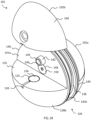
- FIG. 25 is a schematic diagram providing a partially exploded isometric view of a rotatable clamp assembly 101 with one top portion 102b, embodied as a quarter-spherical removable portion, removed.
- the base assembly 126 may comprise two halves having the same or similar features.
- the base assembly 126 may comprise a pair of opposing internal sidewalls 140, which may be spaced apart from each other and separated by the rotation groove 138.
- Each internal sidewall 140 may comprise a first side 141a and a second side 141b.
- a threaded aperture 148 may extend through each internal sidewall 140 to accommodate a screw 150 that may hold the two halves of the base assembly 126 together.
- a magnet nub 142 may extend from the first side 141a of the internal sidewall.
- the magnet nub 142 may comprise a magnet aperture 144, which may be sized and shaped to accommodate a magnet 146.
- the bottom portions 128a, 128b of each half of the base assembly 126 may comprise a base wall 135 that extends perpendicularly from the internal side wall 140.
- the bottom clamp groove 130 may be defined in the base wall 135.
- the base wall 140 may also comprise an aperture 132 to accommodate a magnet 134.
- FIG. 26 is a schematic diagram providing an isometric view and FIG. 27 is a schematic diagram providing an exploded isometric view of a top portion 102a, 102b, embodied as a quarter-spherical removable portion, of a rotatable clamp assembly 101.
- the top portion 102a, 102b may comprise an outer surface 104, a bottom wall 108, and an inner sidewall 118.
- a side nub groove 120 may be defined in the bottom wall 108 and the inner sidewall 118.
- a gripping tool aperture 106 may extend through the outer surface 104 and into the side nub groove 120 to allow a tool (not shown) to be inserted therethrough and to press against an internal sidewall 140 of the base assembly 126 (See: FIGs.
- the side nub groove 120 or the inner sidewall 118 may further comprise an aperture 122 to accommodate a magnet 124, which may cooperate with the magnet 144 (See: FIGs. 24 , 25 ) disposed in one of the internal side walls 140 of the base assembly 126 to secure the top portion 102a, 102b to the base assembly 126.
- the bottom wall 108 may comprise an aperture 114 to accommodate a magnet 116, which may cooperate with the magnet 134 (See: FIGs. 24 , 25 ) disposed in one of the base walls 135 of the base assembly 126 to secure the top portion 102a, 102b to the base assembly 126.
- the bottom wall 108 may also comprise the top clamp groove 110 and the one or more gripping teeth 112, previously described.
- FIG. 28 is a schematic diagram providing a bottom view of a rotatable clamp assembly 101.
- FIG. 29 is a schematic diagram providing an isometric view and
- FIG. 30 is a schematic diagram providing an exploded isometric view along line B-B as shown in FIG. 28 of a rotatable clamp assembly 101.
- the rotatable clamp assembly 101 may comprise a gear 136 disposed between the two halves thereof.
- the gear 136 may be disposed between the internal sidewalls 140 of the two halves of the rotatable clamp assembly 101, such that it is affixed to or integrally formed with the second side 141b of the respective internal side wall 140.
- the threaded aperture 148 may optionally extend through the gear 136.
- the base assembly 126 may further comprise a pair of outer ring grooves 152 and a pair of inner ring grooves 154.
- the outer ring grooves 152 may accommodate outer rings 156 and the inner ring grooves 154 may accommodate inner rings 158.
- the outer rings 156 and the inner rings 154 may comprise a wear resistant material and may protect the base assembly 126 from excessive wear as it rotatably engages the rotatable clamp support 302 of the body 300 (See: FIGs. 14 - 16 ).
- FIG. 31, FIG. 32 , FIG. 33, and FIG. 34 cooperate to illustrate an actuator 500 of a razor component testing apparatus 2 and a function thereof.
- FIG. 31 is a schematic diagram providing an isometric view of an actuator 500 of a razor component testing apparatus 2.
- the actuator 500 may comprise a crank handle 502 rotatably coupled to a drive shaft 504. It is to be appreciated that the drive shaft 504 may also be mechanically actuated.
- the drive shaft 504 may be supported by a frame 506 in which a gear 508 is disposed.
- FIG. 32 is a schematic diagram providing an isometric view of a drive belt 510 of an actuator of a razor component testing apparatus 2.
- the drive belt 510 may comprise a plurality of teeth 512.
- the drive belt 510 may engage the gear 508.
- FIG. 31 is a schematic diagram providing an isometric view of an actuator 500 of a razor component testing apparatus 2.
- the actuator 500 may comprise a plurality of teeth 512.
- the drive belt 510 may engage
- FIG. 33 is a schematic diagram providing a top view of a razor component testing apparatus.
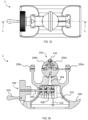
- FIG. 34 is a schematic diagram providing a cross-sectional view of the razor component testing apparatus shown in FIG. 33 , along line C-C.
- the frame 506 may be disposed within an internal cavity 310 of the body 300 of the razor component testing apparatus 2.
- the drive belt 501 may extend through a drive-belt aperture 304 in the body 300 to engage the gear 136 of the rotatable clamp assembly 101.
- the actuator 500 may thereby transfer rotational power from the crank handle 502 (or a suitable mechanical alternative) to the drive shaft 504 to the gear 508.
- the drive belt 510 may transfer rotational power from the gear 508 of the actuator 500 to the gear 136 of the rotatable clamp assembly 101 to rotate the rotatable clamp assembly 101 and thereby the first rotatable clamp 100a simultaneously with the second rotatable clamp 100b.
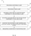
- FIG. 35 is a schematic block diagram of a shaving razor component test method 3.
- the method 3 may comprise a step 10 of providing a rotatable clamp and a step 12 of providing a fixed clamp.
- the method 3 may further comprise a step 14 of securing a first end of a shaving razor component to the rotatable clamp and a step 16 of securing a second end of the shaving razor component to the fixed clamp.
- the method 3 may comprise a step 18 of rotating the rotatable clamp, wherein said rotating causes the shaving razor component to fail.
- the method 3 may further comprise a step 20 of measuring a duration of the rotating step 18.
- FIG. 36 is a schematic block diagram of a shaving razor component test method 4.
- the method 3 may comprise a step 22 of providing a first rotatable clamp and a step 24 of providing a first fixed clamp.
- the method 3 may further comprise a step 26 of securing a first end of a first shaving razor component to the first rotatable clamp and a step 28 of securing a second end of the first shaving razor component to the first fixed clamp.
- the method 3 may further comprise a step 30 of providing a second rotatable clamp and a step 32 of providing a second fixed clamp.
- the method 3 may further comprise a step 34 of securing a first end of a second shaving razor component to the second rotatable clamp and a step 36 of securing a second end of the second shaving razor component to the second fixed clamp.
- the method 3 may further comprise a step 38 of rotating the first rotatable clamp and the second rotatable clamp simultaneously, wherein said rotating causes at least one of the first shaving razor component and the second shaving razor component to fail.
- the method 3 may further comprise a step 40 of measuring a first time, corresponding to a duration of the rotating step 38.
- the method 3 may comprise a step 42 of continuing to rotate the first rotatable clamp and the second rotatable clamp simultaneously, wherein said continued rotating causes at least one of the first shaving razor component and the second shaving razor component to fail.
- the method may comprise a step 44 of measuring a second time, corresponding to a duration of the continuing to rotate step 42.
- the method may comprise a step 46 of displaying, recording, or comparing the first time to the second time.
- the components described herein may be fabricated from any suitable material, including but not limited to plastics, metals, and wood.
Landscapes
- Physics & Mathematics (AREA)
- General Physics & Mathematics (AREA)
- Life Sciences & Earth Sciences (AREA)
- Engineering & Computer Science (AREA)
- General Health & Medical Sciences (AREA)
- Biochemistry (AREA)
- Analytical Chemistry (AREA)
- Chemical & Material Sciences (AREA)
- Immunology (AREA)
- Pathology (AREA)
- Health & Medical Sciences (AREA)
- Forests & Forestry (AREA)
- Mechanical Engineering (AREA)
- Aviation & Aerospace Engineering (AREA)
- Investigating Strength Of Materials By Application Of Mechanical Stress (AREA)
Abstract
Description
- The present disclosure relates generally to methods for testing shaving razor components and more specifically to methods for testing the flexibility, strength, and/or resiliency of shaving razor components.
- Consumers of disposable and system shaving razors (i.e., razor handles having a replaceable razor cartridge) continue to demand improved product performance. As a result, razor manufacturers continually try to improve upon various shaving razor performance attributes that are desired by consumers. However, even when a better shaving razor is designed and manufactured, razor manufacturing companies, advertisers, and retailers face difficulty in communicating to the consumers, especially in a meaningful, clear, and visual manner, that a particular shaving razor component demonstrates improved or more effective performance, comfort, or other benefits compared to other shaving razor products.
- Accordingly, there is a need for an apparatus and/or a method for demonstrating to consumers particular advantages of using certain shaving razors. There is also a need for a method to demonstrate the flexibility, strength, and/or resiliency of shaving razor components and to communicate these differences to consumers clearly.
- The discussion of shortcomings and needs existing in the field prior to the present disclosure is in no way an admission that such shortcomings and needs were recognized by those skilled in the art prior to the present disclosure.
- Various embodiments solve the above-mentioned problems and provide methods useful for demonstrating the flexibility, strength, and/or resiliency of shaving razor components and for communicating these differences to consumers clearly.
- Various embodiments relate to a shaving razor component test method comprising the steps of providing a rotatable clamp, providing a fixed clamp, securing a first end of a shaving razor component to the rotatable clamp, securing a second end of the shaving razor component to the fixed clamp, and rotating the rotatable clamp. The rotating may cause the shaving razor component to fail.
- Various embodiments relate to a shaving razor component test method comprising the steps of providing a first rotatable clamp, providing a first fixed clamp, securing a first end of a first shaving razor component to the first rotatable clamp, securing a second end of the first shaving razor component to the first fixed clamp, providing a second rotatable clamp, providing a second fixed clamp, securing a first end of a second shaving razor component to the second rotatable clamp, securing a second end of the second shaving razor component to the second fixed clamp, and rotating the first rotatable clamp and the second rotatable clamp simultaneously. The rotating may cause at least one of the first shaving razor component and the second shaving razor component to fail.
- These and other features, aspects, and advantages of various embodiments will become better understood with reference to the following description, figures, and claims.
- Many aspects of this disclosure can be better understood with reference to the following figures.
- FIG. 1
- is a schematic diagram providing a front view of a razor component testing apparatus.
- FIG. 2
- is a schematic diagram providing an isometric view of a razor component testing apparatus.
- FIG. 3
- is a schematic diagram providing an isometric view of a razor component testing apparatus during a rotation of a rotatable clamp.
- FIG. 4
- is a schematic diagram providing an isometric view of a razor component.
- FIG. 5
- is a schematic diagram providing an isometric view of a rotatable clamp clamping a razor component.
- FIG. 6
- is a schematic diagram providing an exploded isometric view of a rotatable clamp.
- FIG. 7
- is a schematic diagram providing an exploded isometric bottom view of a rotatable clamp.
- FIG. 8
- is a schematic diagram providing an isometric view of a fixed clamp clamping a razor component.
- FIG. 9
- is a schematic diagram providing an exploded isometric view of a fixed clamp.
- FIG. 10
- is a schematic diagram providing an exploded isometric bottom view of a fixed clamp.
- FIG. 11
- is a schematic diagram providing an isometric view of a razor component testing apparatus.
- FIG. 12
- is a schematic diagram providing an isometric view of a pair of razor components.
- FIG. 13
- is a schematic diagram providing an isometric view of a razor component testing apparatus during a rotation of a rotatable clamp assembly.
- FIG. 14
- is a schematic diagram providing an isometric view of a body of a razor component testing apparatus.
- FIG. 15
- is a schematic diagram providing a top view of a body of a razor component testing apparatus.
- FIG. 16
- is a schematic diagram providing a cross-sectional view of the body of the razor component testing apparatus shown in
FIG. 15 , along line A-A. - FIG. 17
- is a schematic diagram providing an isometric view of fixed clamp of a razor component testing apparatus.
- FIG. 18
- is a schematic diagram providing a front view of a fixed clamp of a razor component testing apparatus.
- FIG. 19
- is a schematic diagram providing an exploded view of a fixed clamp of a razor component testing apparatus.
- FIG. 20
- is a schematic diagram providing an exploded bottom view of a top portion of a fixed clamp of a razor component testing apparatus.
- FIG. 21
- is a schematic diagram providing an isometric view of a fixed clamp of a razor component testing apparatus clamping a razor component.
- FIG. 22
- is a schematic diagram providing an isometric view of a rotatable clamp assembly comprising a first rotatable clamp clamping a first razor component and a second rotatable clamp clamping a second razor component.
- FIG. 23
- is a schematic diagram providing a side view of a rotatable clamp assembly.
- FIG. 24
- is a schematic diagram providing a partially exploded isometric view of a rotatable clamp assembly.
- FIG. 25
- is a schematic diagram providing a partially exploded isometric view of a rotatable clamp assembly with one top portion, embodied as a quarter-spherical removable portion, removed.
- FIG. 26
- is a schematic diagram providing an isometric view of a top portion, embodied as a quarter-spherical removable portion, of a rotatable clamp assembly.
- FIG. 27
- is a schematic diagram providing an exploded isometric view of a top portion, embodied as a quarter-spherical removable portion, of a rotatable clamp assembly.
- FIG. 28
- is a schematic diagram providing a bottom view of a rotatable clamp assembly.
- FIG. 29
- is a schematic diagram providing an isometric view along line B-B as shown in
FIG. 28 of a rotatable clamp assembly. - FIG. 30
- is a schematic diagram providing an exploded isometric view along line B-B as shown in
FIG. 28 of a rotatable clamp assembly. - FIG. 31
- is a schematic diagram providing an isometric view of an actuator of a razor component testing apparatus.
- FIG. 32
- is a schematic diagram providing an isometric view of a drive belt of an actuator of a razor component testing apparatus.
- FIG. 33
- is a schematic diagram providing a top view of a razor component testing apparatus.
- FIG. 34
- is a schematic diagram providing a cross-sectional view of the razor component testing apparatus shown in
FIG. 33 , along line C-C. - FIG. 35
- is a schematic block diagram of a shaving razor component test method.
- FIG. 36
- is a schematic block diagram of a shaving razor component test method.
- It should be understood that the various embodiments are not limited to the examples illustrated in the figures.
- This disclosure is written to describe the invention to a person having ordinary skill in the art, who will understand that this disclosure is not limited to the specific examples or embodiments described. The examples and embodiments are single instances of the invention which will make a much larger scope apparent to the person having ordinary skill in the art. Unless defined otherwise, all technical and scientific terms used herein have the same meaning as commonly understood by the person having ordinary skill in the art. It is also to be understood that the terminology used herein is for the purpose of describing examples and embodiments only, and is not intended to be limiting, since the scope of the present disclosure will be limited only by the appended claims.
- All the features disclosed in this specification (including any accompanying claims, abstract, and drawings) may be replaced by alternative features serving the same, equivalent, or similar purpose, unless expressly stated otherwise. Thus, unless expressly stated otherwise, each feature disclosed is one example only of a generic series of equivalent or similar features. The examples and embodiments described herein are for illustrative purposes only and that various modifications or changes in light thereof will be suggested to the person having ordinary skill in the art and are to be included within the spirit and purview of this application. Many variations and modifications may be made to the embodiments of the disclosure without departing substantially from the spirit and principles of the disclosure. All such modifications and variations are intended to be included herein within the scope of this disclosure. For example, unless otherwise indicated, the present disclosure is not limited to particular materials, reagents, reaction materials, manufacturing processes, or the like, as such can vary. It is also to be understood that the terminology used herein is for purposes of describing particular embodiments only and is not intended to be limiting. It is also possible in the present disclosure that steps can be executed in different sequence where this is logically possible.
- All numeric values are herein assumed to be modified by the term "about," whether or not explicitly indicated. The term "about" generally refers to a range of numbers that one of skill in the art would consider equivalent to the recited value (for example, having the same function or result). In many instances, the term "about" may include numbers that are rounded to the nearest significant figure.
- In everyday usage, indefinite articles (like "a" or "an") precede countable nouns and noncountable nouns almost never take indefinite articles. It must be noted, therefore, that, as used in this specification and in the claims that follow, the singular forms "a," "an," and "the" include plural referents unless the context clearly dictates otherwise. Thus, for example, reference to "a support" includes a plurality of supports. Particularly when a single countable noun is listed as an element in a claim, this specification will generally use a phrase such as "a single." For example, "a single support."
- Where a range of values is provided, it is understood that each intervening value, to the tenth of the unit of the lower limit (unless the context clearly dictates otherwise), between the upper and lower limit of that range, and any other stated or intervening value in that stated range, is encompassed within the disclosure. The upper and lower limits of these smaller ranges may independently be included in the smaller ranges and are also encompassed within the disclosure, subject to any specifically excluded limit in the stated range. Where the stated range includes one or both of the limits, ranges excluding either or both of those included limits are also included in the disclosure.
-
FIG. 1, FIG. 2 , andFIG. 3 cooperate to illustrate a shaving razorcomponent testing apparatus 1 and a function thereof. The razorcomponent testing apparatus 1 may comprise arotatable clamp 100, and afixed clamp 200, which are both mounted to abody 300. Therotatable clamp 100 may be rotatably coupled to anactuator 500. Theactuator 500 may comprise a crankhandle 502 and ashaft 504 that may rotate within aframe 506. Theframe 506 may be mounted to or integrally formed with thebody 300.FIG. 3 shows the razorcomponent testing apparatus 1 during a rotation of therotatable clamp 500. When theactuator 500 is rotated, therotatable clamp 100 may rotate and the fixedclamp 200 may remain stationary. The rotation may twist a shavingrazor component 400 clamped between therotatable clamp 100 and the fixedclamp 200. The twisting may eventually cause the shavingrazor component 400 to fail. This test may facilitate a comparison of the flexibility, strength, and/or resiliency of shaving razor components, including, for example, components comprising different materials, such as ethyl vinyl acetate or high impact polystyrene. -
FIG. 4 is a schematic diagram providing an isometric view of arazor component 400. Therazor component 400 may have afirst end 401 and asecond end 402. Thefirst end 401 may be clamped in therotatable clamp 100. Thesecond end 402 may be clamped in the fixedclamp 200. Therazor component 400 may be any type of component, including for example a component made of ethyl vinyl acetate or high impact polystyrene. Therazor component 400 may have any shape, for example, an extended T-shape as illustrated, comprising a horizontally extendingtop portion 404 and a vertically extendingbottom portion 406 that is perpendicular to the horizontally extendingtop portion 404. -
FIG. 5, FIG. 6, and FIG. 7 cooperate to illustrate various views of arotatable clamp 100 of a razorcomponent testing apparatus 1.FIG. 5 is a schematic diagram providing an isometric view of arotatable clamp 100 clamping arazor component 400. Therotatable clamp 100 may comprise atop portion 102 and abottom portion 128. Thetop portion 102 may comprise one ormore apertures 114, which may accommodate a magnet, a bolt, or a nut to secure thetop portion 102 to thebottom portion 128. Therotatable clamp 100 may be rotatably coupled to adrive shaft 504 of anactuator 500.FIG. 6 is a schematic diagram providing an exploded isometric view of arotatable clamp 100. Thebottom portion 128 may comprise one ormore apertures 132, which may accommodate a magnet, a bolt, or a nut to secure thebottom portion 128 to thetop portion 102. Thebottom portion 128 may further comprise abottom clamp groove 130 that may be shaped to receive a shavingrazor component 400 or a portion thereof, such as, for example a vertically extendingbottom portion 406 of arazor component 400 having an extended T-shape (See:FIG. 4 ). As will be discussed hereinafter, although not shown here, thetop portion 102 may comprise a top clamp groove which may also be shaped to receive a shavingrazor component 400. Such a top clamp groove make cooperate with thebottom clamp groove 130 to receive the shavingrazor component 400.FIG. 7 is a schematic exploded isometric bottom view of arotatable clamp 100, showing that theaperture 132 in thebottom portion 128 may receive a nut (not shown) to engage with a bolt (not shown) or a magnet (not shown) passing through theapertures 114 of thetop portion 102. -
FIG. 8, FIG. 9, and FIG. 10 cooperate to illustrate various views of a fixedclamp 100 of a razorcomponent testing apparatus 1.FIG. 8 is a schematic diagram providing an isometric view of a fixedclamp 200 clamping arazor component 400. The fixedclamp 200 may comprise atop portion 202 and abottom portion 214. Thetop portion 202 may comprise one ormore apertures 208, which may accommodate a magnet, a bolt, or a nut to secure thetop portion 202 to thebottom portion 214. The fixedclamp 200 or thebottom portion 214 thereof may be rigidly affixed to or integrally formed with abody 300 of a razor component testing apparatus 2 (See:FIG. 14 ).FIG. 9 is a schematic diagram providing an exploded isometric view of a fixedclamp 200 andFIG. 10 is a schematic diagram providing an exploded isometric bottom view of a fixedclamp 200. Thebottom portion 214 may comprise one ormore apertures 218, which may accommodate a magnet, a bolt, or a nut to secure thebottom portion 214 to thetop portion 202. Thebottom portion 214 may further comprise abottom clamp groove 216 that may be shaped to receive a shavingrazor component 400. As will be discussed hereinafter, although not shown here, thetop portion 202 may comprise a top clamp groove which may also be shaped to receive a shavingrazor component 400. Such a top clamp groove may cooperate with thebottom clamp groove 216 to receive the shavingrazor component 400. - It is to be appreciated that any of the
apertures clamp 100 or therotatable clamp 200 may be configured to receive a magnet, to receive a nut (not shown), to receive a bolt (not shown) or to receive any other suitable device for generating a clamping force between thetop portions bottom portions specific razor components 400 to avoid crushing therazor component 400 and to allow therazor component 400 to fail between therotatable clamp 100 and the fixedclamp 200 instead of at the point where therazor component 400 is gripped by therotatable clamp 100 or by the fixedclamp 200. -
FIG. 11, FIG. 12 , andFIG. 13 cooperate to illustrate a shaving razorcomponent testing apparatus 2 and a function thereof.FIG. 11 is an isometric view of a razorcomponent testing apparatus 2. The razorcomponent testing apparatus 2 may comprise arotatable clamp assembly 101. Therotatable clamp assembly 101 may comprise a firstrotatable clamp 100a and a secondrotatable clamp 100b. The razorcomponent testing apparatus 2 may further comprise a firstfixed clamp 200a and a secondfixed clamp 200b. Therotatable clamp assembly 101 as well as the firstfixed clamp 200a and the secondfixed clamp 200b may be mounted to abody 300. As previously stated, therazor components top portion 404a, b and a vertically extendingbottom portion 406a, b that is perpendicular to the horizontally extendingtop portion 404. -
FIG. 12 is a schematic diagram providing an isometric view of a pair ofrazor components shaving razor component 400a may comprise afirst end 402a and asecond end 402b. Similarly, the secondshaving razor component 400b may comprise afirst end 401b and asecond end 402b. The firstshaving razor component 400a may be clamped between the firstrotatable clamp 100a and the firstfixed clamp 200a. For example, thefirst end 401a of the firstshaving razor component 400a may be clamped in the firstrotatable clamp 100a while thesecond end 402a of the firstshaving razor component 400a may be clamped in the firstfixed clamp 200a. In like manner, the secondshaving razor component 400b may be clamped between the secondrotatable clamp 100b and the secondfixed clamp 200b. For example, thefirst end 401b of the secondshaving razor component 400b may be clamped in the secondrotatable clamp 100b while thesecond end 402b of the secondshaving razor component 400b may be clamped in the secondfixed clamp 200b. -
FIG. 13 is a schematic diagram providing an isometric view of a razorcomponent testing apparatus 2 during a rotation of arotatable clamp assembly 101 thereof. As shown in bothFIG. 11 andFIG. 13 , the razorcomponent testing apparatus 2 may further comprise anactuator 500, which, as will be described hereinafter, may transfer rotational power to therotatable clamp assembly 101 to rotate both the firstrotatable clamp 100a and the secondrotatable clamp 100b simultaneously. When therotatable clamp assembly 101 is rotated, the firstshaving razor component 400a and the secondshaving razor component 400b may be twisted as shown inFIG. 13 . The twisting may eventually cause one of the shavingrazor components -
FIG. 14 ,FIG. 15, and FIG. 16 cooperate to illustrate abody 300 of a razorcomponent testing apparatus 2.FIG. 14 is a schematic diagram providing an isometric view of abody 300 of a razorcomponent testing apparatus 2.FIG. 15 is a schematic diagram providing a top view of abody 300 of a razorcomponent testing apparatus 2.FIG. 16 is a schematic diagram providing a cross-sectional view of thebody 300 of the razorcomponent testing apparatus 2 shown inFIG. 15 , along line A-A. Thebody 300 may define adrive belt aperture 304 through which a drive belt 510 (See:FIG. 32 ) may pass. Thebody 300 may also define anactuator shaft aperture 306 through which adrive shaft 504 may pass. Thebody 300 may further define anactuator clearance groove 308 to provide clearance for a crank handle 502 of an actuator 500 (See:FIG. 31 ). Next, thebody 300 may comprise arotatable clamp support 302 to accommodate a rotatable clamp assembly 101 (See:FIG. 22 ). Finally, it is to be appreciated that the previously mentionedbottom portion 214a of a firstfixed clamp 200a and abottom portion 214b of a secondfixed clamp 200b may be integrally formed with thebody 300 or otherwise affixed thereto. -
FIG. 17, FIG. 18 ,FIG. 19 ,FIG. 20, and FIG. 21 cooperate to illustrate one type of fixedclamp component testing apparatuses clamp component testing apparatuses -
FIG. 17 is a schematic diagram providing an isometric view andFIG. 18 is a schematic diagram providing a front view of fixedclamp component testing apparatus clamp top portion bottom portion top portion top clamp groove 204. One or moregripping teeth 206 may be defined within thetop clamp groove 204. Thetop portion grip 212 to allow a user to handle thetop portion grip 212 may, for example, facilitate the attachment or detachment of thetop portion bottom portion bottom portion bottom clamp groove 216. Thetop clamp groove 204 and thebottom clamp groove 216 may be a pair of cooperating grooves shaped to receive afirst end second end razor component FIG. 4 orFIG. 12 ). The one or moregripping teeth 206 may be positioned within the pair of cooperatinggrooves top portion 404 of arazor component 400 that has an extended T-shape (See:FIG. 4 , andFIG. 12 ). -
FIG. 19 is a schematic diagram providing an exploded view of fixedclamp component testing apparatus bottom portion more apertures 218, which may accommodate amagnet 210, a bolt, or a nut.FIG. 20 is a schematic exploded bottom view of atop portion clamp component testing apparatus top portion more apertures 208, which may accommodate amagnet 210, a bolt, or a nut. Cooperation of themagnets 210 or other suitable devices may generate a clamping force between thetop portion corresponding bottom portion -
FIG. 21 is a schematic diagram providing an isometric view of a fixedclamp razor component gripping teeth 206 may press against the horizontally extendingtop portion 404 of the extended T-shapedrazor component 400. The number and positioning of the grippingteeth 206 may be calibrated along with the clamping force for specific razor component(s) 400, 400a, 400b to avoid crushing therazor component rotatable clamp clamp -
FIG. 22, FIG. 23 ,FIG. 24 ,FIG. 25 ,FIG. 26, FIG. 27 ,FIG. 28, FIG. 29 ,FIG. 30 , andFIG. 31 cooperate to illustrate arotatable clamp assembly 101 and various components thereof. The rotatable clamp assembly may comprise a firstrotatable clamp 100a and a secondrotatable clamp 100b. These rotatable clamps 100a, 100b exemplify one type ofrotatable clamp component testing apparatuses rotatable clamp component testing apparatuses -
FIG. 22 is a schematic diagram providing an isometric view andFIG. 23 is a schematic diagram providing a side view of arotatable clamp assembly 101 comprising a firstrotatable clamp 100a clamping afirst razor component 400a and a secondrotatable clamp 100b clamping asecond razor component 400b. The firstrotatable clamp 100a may comprise atop portion 102a and abottom portion 128a. Similarly, the secondrotatable clamp 100b may comprise atop portion 102b and abottom portion 128b. It is to be appreciated that thetop portions bottom portions rotatable clamp 100a and the secondrotatable clamp 100b may have the same or similar features. - The
top portions outer surface 104. Theouter surface 104 may comprise agripping tool aperture 106 to allow a tool (not shown) to be inserted into thetop portion 102b to make it easier for a user to detach thetop portion base assembly 126. Thebottom portions base assembly 126, such that thebase assembly 126 may comprise bothbottom portions base assembly 126 may define arotation groove 138, which may be rotatably coupled to arotatable clamp support 302 of theirbody 300 of a razor component testing apparatus 2 (See:FIGs. 14 - 16 ). - The
top portions top clamp groove 110. One or moregripping teeth 112 may be defined within thetop clamp groove 110. Thebottom portions bottom clamp groove 130. Thetop clamp groove 110 and thebottom clamp groove 130 may be a pair of cooperating grooves shaped to receive afirst end second end razor component FIG. 4 orFIG. 12 ). The one or moregripping teeth 112 may be positioned within the pair of cooperatinggrooves top portion 404 of arazor component 400 that has an extended T-shape (See:FIG. 4 , andFIG. 12 ). The number and positioning of the grippingteeth 112 may be calibrated along with the clamping force for specific razor component(s) 400, 400a, 400b to avoid crushing therazor component rotatable clamp clamp -
FIG. 24 is a schematic diagram providing a partially exploded isometric view of arotatable clamp assembly 101.FIG. 25 is a schematic diagram providing a partially exploded isometric view of arotatable clamp assembly 101 with onetop portion 102b, embodied as a quarter-spherical removable portion, removed. Although only one half of thebase assembly 126 is exposed and illustrated, it is to be appreciated that thebase assembly 126 may comprise two halves having the same or similar features. Thebase assembly 126 may comprise a pair of opposinginternal sidewalls 140, which may be spaced apart from each other and separated by therotation groove 138. Eachinternal sidewall 140 may comprise afirst side 141a and asecond side 141b. A threadedaperture 148 may extend through eachinternal sidewall 140 to accommodate ascrew 150 that may hold the two halves of thebase assembly 126 together. Amagnet nub 142 may extend from thefirst side 141a of the internal sidewall. Themagnet nub 142 may comprise amagnet aperture 144, which may be sized and shaped to accommodate amagnet 146. Thebottom portions base assembly 126 may comprise abase wall 135 that extends perpendicularly from theinternal side wall 140. Thebottom clamp groove 130 may be defined in thebase wall 135. Thebase wall 140 may also comprise anaperture 132 to accommodate amagnet 134. -
FIG. 26 is a schematic diagram providing an isometric view andFIG. 27 is a schematic diagram providing an exploded isometric view of atop portion rotatable clamp assembly 101. Thetop portion outer surface 104, abottom wall 108, and aninner sidewall 118. Aside nub groove 120 may be defined in thebottom wall 108 and theinner sidewall 118. Agripping tool aperture 106 may extend through theouter surface 104 and into theside nub groove 120 to allow a tool (not shown) to be inserted therethrough and to press against aninternal sidewall 140 of the base assembly 126 (See:FIGs. 24 ,25 ) to detach atop portion base assembly 126. Theside nub groove 120 or theinner sidewall 118 may further comprise anaperture 122 to accommodate amagnet 124, which may cooperate with the magnet 144 (See:FIGs. 24 ,25 ) disposed in one of theinternal side walls 140 of thebase assembly 126 to secure thetop portion base assembly 126. Similarly, thebottom wall 108 may comprise anaperture 114 to accommodate amagnet 116, which may cooperate with the magnet 134 (See:FIGs. 24 ,25 ) disposed in one of thebase walls 135 of thebase assembly 126 to secure thetop portion base assembly 126. Thebottom wall 108 may also comprise thetop clamp groove 110 and the one or moregripping teeth 112, previously described. -
FIG. 28 is a schematic diagram providing a bottom view of arotatable clamp assembly 101.FIG. 29 is a schematic diagram providing an isometric view andFIG. 30 is a schematic diagram providing an exploded isometric view along line B-B as shown inFIG. 28 of arotatable clamp assembly 101. Therotatable clamp assembly 101 may comprise agear 136 disposed between the two halves thereof. For example, thegear 136 may be disposed between theinternal sidewalls 140 of the two halves of therotatable clamp assembly 101, such that it is affixed to or integrally formed with thesecond side 141b of the respectiveinternal side wall 140. The threadedaperture 148 may optionally extend through thegear 136. Thebase assembly 126 may further comprise a pair ofouter ring grooves 152 and a pair ofinner ring grooves 154. Theouter ring grooves 152 may accommodateouter rings 156 and theinner ring grooves 154 may accommodateinner rings 158. The outer rings 156 and theinner rings 154 may comprise a wear resistant material and may protect thebase assembly 126 from excessive wear as it rotatably engages therotatable clamp support 302 of the body 300 (See:FIGs. 14 - 16 ). -
FIG. 31, FIG. 32 ,FIG. 33, and FIG. 34 cooperate to illustrate anactuator 500 of a razorcomponent testing apparatus 2 and a function thereof.FIG. 31 is a schematic diagram providing an isometric view of anactuator 500 of a razorcomponent testing apparatus 2. Theactuator 500 may comprise a crankhandle 502 rotatably coupled to adrive shaft 504. It is to be appreciated that thedrive shaft 504 may also be mechanically actuated. Thedrive shaft 504 may be supported by aframe 506 in which agear 508 is disposed.FIG. 32 is a schematic diagram providing an isometric view of adrive belt 510 of an actuator of a razorcomponent testing apparatus 2. Thedrive belt 510 may comprise a plurality ofteeth 512. Thedrive belt 510 may engage thegear 508.FIG. 33 is a schematic diagram providing a top view of a razor component testing apparatus.FIG. 34 is a schematic diagram providing a cross-sectional view of the razor component testing apparatus shown inFIG. 33 , along line C-C. Theframe 506 may be disposed within aninternal cavity 310 of thebody 300 of the razorcomponent testing apparatus 2. The drive belt 501 may extend through a drive-belt aperture 304 in thebody 300 to engage thegear 136 of therotatable clamp assembly 101. Theactuator 500 may thereby transfer rotational power from the crank handle 502 (or a suitable mechanical alternative) to thedrive shaft 504 to thegear 508. Thedrive belt 510 may transfer rotational power from thegear 508 of theactuator 500 to thegear 136 of therotatable clamp assembly 101 to rotate therotatable clamp assembly 101 and thereby the firstrotatable clamp 100a simultaneously with the secondrotatable clamp 100b. -
FIG. 35 is a schematic block diagram of a shaving razorcomponent test method 3. Themethod 3 may comprise astep 10 of providing a rotatable clamp and astep 12 of providing a fixed clamp. Themethod 3 may further comprise astep 14 of securing a first end of a shaving razor component to the rotatable clamp and astep 16 of securing a second end of the shaving razor component to the fixed clamp. Next, themethod 3 may comprise astep 18 of rotating the rotatable clamp, wherein said rotating causes the shaving razor component to fail. Finally, themethod 3 may further comprise astep 20 of measuring a duration of therotating step 18. -
FIG. 36 is a schematic block diagram of a shaving razorcomponent test method 4. Themethod 3 may comprise astep 22 of providing a first rotatable clamp and astep 24 of providing a first fixed clamp. Themethod 3 may further comprise astep 26 of securing a first end of a first shaving razor component to the first rotatable clamp and astep 28 of securing a second end of the first shaving razor component to the first fixed clamp. Themethod 3 may further comprise astep 30 of providing a second rotatable clamp and astep 32 of providing a second fixed clamp. Themethod 3 may further comprise astep 34 of securing a first end of a second shaving razor component to the second rotatable clamp and astep 36 of securing a second end of the second shaving razor component to the second fixed clamp. Themethod 3 may further comprise a step 38 of rotating the first rotatable clamp and the second rotatable clamp simultaneously, wherein said rotating causes at least one of the first shaving razor component and the second shaving razor component to fail. Themethod 3 may further comprise astep 40 of measuring a first time, corresponding to a duration of the rotating step 38. Thereafter, themethod 3 may comprise astep 42 of continuing to rotate the first rotatable clamp and the second rotatable clamp simultaneously, wherein said continued rotating causes at least one of the first shaving razor component and the second shaving razor component to fail. Next, the method may comprise astep 44 of measuring a second time, corresponding to a duration of the continuing to rotatestep 42. Finally, the method may comprise astep 46 of displaying, recording, or comparing the first time to the second time. - The components described herein may be fabricated from any suitable material, including but not limited to plastics, metals, and wood.
- The dimensions and values disclosed herein are not to be understood as being strictly limited to the exact numerical values recited. Instead, unless otherwise specified, each such dimension is intended to mean both the recited value and a functionally equivalent range surrounding that value. For example, a dimension disclosed as "40 mm" is intended to mean "about 40 mm."
Claims (10)
- A shaving razor component test method (4) comprising the steps of:providing (22) a first rotatable clamp (100a);providing (24) a first fixed clamp (200a);securing (26) a first end (401a) of a first shaving razor component (400a) to the first rotatable clamp (100a);securing (28) a second end (402a) of the first shaving razor component (400a) to the first fixed clamp (200a);providing (30) a second rotatable clamp (100b);providing (32) a second fixed clamp (200b);securing (34) a first end (401b) of a second shaving razor component (400b) to the second rotatable clamp (100b);securing (36) a second end (402b) of the second shaving razor component (400b) to the second fixed clamp (200b); androtating (38) the first rotatable clamp (100a) and the second rotatable clamp (100b) simultaneously, wherein said rotating (38) causes at least one of the first shaving razor component (400a) and the second shaving razor component (400b) to fail.
- A shaving razor component test method (4) according to Claim 1, wherein the first rotatable clamp (100a) comprises a first plurality of magnets (116, 124) and the first fixed clamp (200a) comprises a second plurality of magnets (210, 220).
- A shaving razor component test method (4) according to Claim 2, wherein the first plurality of magnets (116, 124) imparts a first clamping force of about 1 N to about 30 N to the first end (401a) of the first shaving razor component (400a), and
wherein the second plurality of magnets (210, 220) imparts a second clamping force of about 1 N to about 30 N to the second end (402a) of the first shaving razor component (400a). - A shaving razor component test method (4) according to any one of Claims 1 to 3, wherein the second rotatable clamp (100b) comprises comprise a third plurality of magnets (116, 124) and the second fixed claim (200b) comprises a fourth plurality of magnets (210, 220).
- A shaving razor component test method (4) according to Claim 4, wherein the third plurality of magnets (116, 124) imparts a first clamping force of about 1 N to about 30 N to the first end (401b) of the second shaving razor component (400b), and wherein the fourth plurality of magnets (210, 220) imparts a second clamping force of about 1 N to about 30 N to the second end (402b) of the second shaving razor component (400b).
- A shaving razor component test method (4) according to any one of Claims 1 to 5, wherein the first rotatable clamp (100a) comprises a first pair of cooperating grooves (110, 130) shaped to receive the first end (401a) of the first shaving razor component (400a), and
wherein the first fixed clamp (200a) comprises a second pair of cooperating grooves (204, 216) shaped to receive the second end (402a) of the first shaving razor component (400a). - A shaving razor component test method (4) according to Claim 6, wherein the first rotatable clamp (100a) further comprises a first pair of gripping teeth (112) disposed in at least one (110) of the first pair of cooperating grooves (110, 130), and wherein the first fixed clamp (200a) further comprises a second pair of gripping teeth (206) disposed in at least one of the second pair of cooperating grooves (204, 216).
- A shaving razor component test method (4) according to any one of Claims 1 to 7, wherein the second rotatable clamp (100b) comprises a first pair of cooperating grooves (110, 130) shaped to receive the first end (401b) of the second shaving razor component (400b), and
wherein the second fixed clamp (200b) comprises a second pair of cooperating grooves (204, 216) shaped to receive the second end (401b) of the second shaving razor component (400b). - A shaving razor component test method (4) according to any one of Claims 1 to 8, wherein the second rotatable clamp (100b) further comprises a first pair of gripping teeth (112) disposed in at least one (110) of the first pair of cooperating grooves (110, 130), and
wherein the second fixed clamp (200b) further comprises a second pair of gripping teeth (206) disposed in at least one (204) of the second pair of cooperating grooves (204, 216). - A shaving razor component test method (4) according to any one of Claims 1 to 9, further comprising measuring (40) a first time, corresponding to a duration of the rotating step,continuing to rotate the first rotatable clamp (100a) and the second rotatable clamp (100b) simultaneously, wherein said continued rotating causes at least one of the first shaving razor component (400a) and the second shaving razor component (400b) to fail,measuring (44) a second time, corresponding to a duration of the continuing to rotate step, andcomparing (46) the first time to the second time.
Applications Claiming Priority (1)
| Application Number | Priority Date | Filing Date | Title |
|---|---|---|---|
| US18/135,509 US12617110B2 (en) | 2023-04-17 | 2023-04-17 | Shaving razor component test method |
Publications (2)
| Publication Number | Publication Date |
|---|---|
| EP4450942A1 true EP4450942A1 (en) | 2024-10-23 |
| EP4450942B1 EP4450942B1 (en) | 2025-11-05 |
Family
ID=90468452
Family Applications (1)
| Application Number | Title | Priority Date | Filing Date |
|---|---|---|---|
| EP24165921.8A Active EP4450942B1 (en) | 2023-04-17 | 2024-03-25 | Shaving razor component test method |
Country Status (2)
| Country | Link |
|---|---|
| US (1) | US12617110B2 (en) |
| EP (1) | EP4450942B1 (en) |
Citations (4)
| Publication number | Priority date | Publication date | Assignee | Title |
|---|---|---|---|---|
| CN105372125A (en) * | 2015-12-23 | 2016-03-02 | 济南科汇试验设备有限公司 | Fixture tooling for torsion testing machine and using method of fixture tooling |
| EP3160832A1 (en) * | 2014-06-25 | 2017-05-03 | Barnes, David Lorin | An automated lifting stand for a recreational vehicle |
| CN109459169A (en) * | 2018-11-02 | 2019-03-12 | 江苏乾涌控股有限公司 | A kind of multi-functional dynameter |
| EP3546156A1 (en) * | 2018-03-30 | 2019-10-02 | The Gillette Company LLC | Razor handle with a pivoting portion |
Family Cites Families (2)
| Publication number | Priority date | Publication date | Assignee | Title |
|---|---|---|---|---|
| US10751895B2 (en) * | 2017-05-19 | 2020-08-25 | The Gillette Company Llc | Apparatus for testing razor blades and method for same |
| US11491832B2 (en) | 2018-02-27 | 2022-11-08 | Methode Electronics, Inc. | Towing systems and methods using magnetic field sensing |
-
2023
- 2023-04-17 US US18/135,509 patent/US12617110B2/en active Active
-
2024
- 2024-03-25 EP EP24165921.8A patent/EP4450942B1/en active Active
Patent Citations (4)
| Publication number | Priority date | Publication date | Assignee | Title |
|---|---|---|---|---|
| EP3160832A1 (en) * | 2014-06-25 | 2017-05-03 | Barnes, David Lorin | An automated lifting stand for a recreational vehicle |
| CN105372125A (en) * | 2015-12-23 | 2016-03-02 | 济南科汇试验设备有限公司 | Fixture tooling for torsion testing machine and using method of fixture tooling |
| EP3546156A1 (en) * | 2018-03-30 | 2019-10-02 | The Gillette Company LLC | Razor handle with a pivoting portion |
| CN109459169A (en) * | 2018-11-02 | 2019-03-12 | 江苏乾涌控股有限公司 | A kind of multi-functional dynameter |
Also Published As
| Publication number | Publication date |
|---|---|
| US20240342936A1 (en) | 2024-10-17 |
| US12617110B2 (en) | 2026-05-05 |
| EP4450942B1 (en) | 2025-11-05 |
Similar Documents
| Publication | Publication Date | Title |
|---|---|---|
| EP0156681B1 (en) | Nut setting tool | |
| CA2705571C (en) | Apparatus for converting side-to-side driving motion to rotational motion with a spring assembly and system for tuning the spring assembly | |
| EP4450942B1 (en) | Shaving razor component test method | |
| EP4450943A1 (en) | Shaving razor component test apparatus | |
| CA2640504A1 (en) | Torque-enabling drive tool holder | |
| US12161521B2 (en) | Electrical brush handpiece and an electrical toothbrush having the electrical brush handpiece and an attachment brush | |
| CN103170943B (en) | Screwdriver | |
| WO2020245684A1 (en) | Sheath assembly mechanism | |
| US6415515B1 (en) | System, apparatus, and method for blade clearance tuning | |
| WO2019040718A1 (en) | Tool and tool holder assembly | |
| JP4528629B2 (en) | System for removably connecting an instrument including a drive member to a driven member having a workpiece | |
| US12576304B2 (en) | Exercise machines, crankshaft assemblies for exercise machines, and methods of disassembling exercise machines having crank arms | |
| JP2006078279A (en) | Test method and testing device of rubber elasticity characteristic material | |
| JP3233081B2 (en) | Gripper | |
| US20250262719A1 (en) | A holding device for abrasive strips and use of a holding device | |
| CN216256904U (en) | A limit brush subassembly and cleaning device for cleaning device | |
| JP3192239B2 (en) | Hair removal device | |
| CN214445898U (en) | Spanner convenient to adjust | |
| CN111151809A (en) | A wire cutter with an adjustable handle angle | |
| JP7841745B2 (en) | Crimping tool for attaching metal fittings | |
| CN223259660U (en) | Ultrasonic scanning clamp for discrete device | |
| CN221175308U (en) | Tightly-fixed adjustable handle | |
| CN109848920B (en) | Ring gear formula extracting tool | |
| JP3107245U (en) | Caulking tool | |
| CN210500000U (en) | Chain spanner |
Legal Events
| Date | Code | Title | Description |
|---|---|---|---|
| PUAI | Public reference made under article 153(3) epc to a published international application that has entered the european phase |
Free format text: ORIGINAL CODE: 0009012 |
|
| STAA | Information on the status of an ep patent application or granted ep patent |
Free format text: STATUS: THE APPLICATION HAS BEEN PUBLISHED |
|
| AK | Designated contracting states |
Kind code of ref document: A1 Designated state(s): AL AT BE BG CH CY CZ DE DK EE ES FI FR GB GR HR HU IE IS IT LI LT LU LV MC ME MK MT NL NO PL PT RO RS SE SI SK SM TR |
|
| STAA | Information on the status of an ep patent application or granted ep patent |
Free format text: STATUS: REQUEST FOR EXAMINATION WAS MADE |
|
| 17P | Request for examination filed |
Effective date: 20250214 |
|
| GRAP | Despatch of communication of intention to grant a patent |
Free format text: ORIGINAL CODE: EPIDOSNIGR1 |
|
| STAA | Information on the status of an ep patent application or granted ep patent |
Free format text: STATUS: GRANT OF PATENT IS INTENDED |
|
| INTG | Intention to grant announced |
Effective date: 20250625 |
|
| GRAS | Grant fee paid |
Free format text: ORIGINAL CODE: EPIDOSNIGR3 |
|
| GRAA | (expected) grant |
Free format text: ORIGINAL CODE: 0009210 |
|
| STAA | Information on the status of an ep patent application or granted ep patent |
Free format text: STATUS: THE PATENT HAS BEEN GRANTED |
|
| AK | Designated contracting states |
Kind code of ref document: B1 Designated state(s): AL AT BE BG CH CY CZ DE DK EE ES FI FR GB GR HR HU IE IS IT LI LT LU LV MC ME MK MT NL NO PL PT RO RS SE SI SK SM TR |
|
| REG | Reference to a national code |
Ref country code: CH Ref legal event code: F10 Free format text: ST27 STATUS EVENT CODE: U-0-0-F10-F00 (AS PROVIDED BY THE NATIONAL OFFICE) Effective date: 20251105 Ref country code: GB Ref legal event code: FG4D |
|
| REG | Reference to a national code |
Ref country code: DE Ref legal event code: R096 Ref document number: 602024001135 Country of ref document: DE |
|
| REG | Reference to a national code |
Ref country code: IE Ref legal event code: FG4D |
|
| P01 | Opt-out of the competence of the unified patent court (upc) registered |
Free format text: CASE NUMBER: UPC_APP_0017748_4450942/2025 Effective date: 20251216 |
|
| REG | Reference to a national code |
Ref country code: NL Ref legal event code: MP Effective date: 20251105 |
|
| PG25 | Lapsed in a contracting state [announced via postgrant information from national office to epo] |
Ref country code: ES Free format text: LAPSE BECAUSE OF FAILURE TO SUBMIT A TRANSLATION OF THE DESCRIPTION OR TO PAY THE FEE WITHIN THE PRESCRIBED TIME-LIMIT Effective date: 20251105 |
|
| REG | Reference to a national code |
Ref country code: LT Ref legal event code: MG9D |
|
| PG25 | Lapsed in a contracting state [announced via postgrant information from national office to epo] |
Ref country code: NO Free format text: LAPSE BECAUSE OF FAILURE TO SUBMIT A TRANSLATION OF THE DESCRIPTION OR TO PAY THE FEE WITHIN THE PRESCRIBED TIME-LIMIT Effective date: 20260205 |
|
| PGFP | Annual fee paid to national office [announced via postgrant information from national office to epo] |
Ref country code: DE Payment date: 20260204 Year of fee payment: 3 |
|
| PG25 | Lapsed in a contracting state [announced via postgrant information from national office to epo] |
Ref country code: HR Free format text: LAPSE BECAUSE OF FAILURE TO SUBMIT A TRANSLATION OF THE DESCRIPTION OR TO PAY THE FEE WITHIN THE PRESCRIBED TIME-LIMIT Effective date: 20251105 Ref country code: AT Free format text: LAPSE BECAUSE OF FAILURE TO SUBMIT A TRANSLATION OF THE DESCRIPTION OR TO PAY THE FEE WITHIN THE PRESCRIBED TIME-LIMIT Effective date: 20251105 Ref country code: FI Free format text: LAPSE BECAUSE OF FAILURE TO SUBMIT A TRANSLATION OF THE DESCRIPTION OR TO PAY THE FEE WITHIN THE PRESCRIBED TIME-LIMIT Effective date: 20251105 |
|
| PGFP | Annual fee paid to national office [announced via postgrant information from national office to epo] |
Ref country code: AT Payment date: 20260301 Year of fee payment: 3 |
|
| REG | Reference to a national code |
Ref country code: AT Ref legal event code: MK05 Ref document number: 1854824 Country of ref document: AT Kind code of ref document: T Effective date: 20251105 |
|
| PG25 | Lapsed in a contracting state [announced via postgrant information from national office to epo] |
Ref country code: NL Free format text: LAPSE BECAUSE OF FAILURE TO SUBMIT A TRANSLATION OF THE DESCRIPTION OR TO PAY THE FEE WITHIN THE PRESCRIBED TIME-LIMIT Effective date: 20251105 |
|
| PG25 | Lapsed in a contracting state [announced via postgrant information from national office to epo] |
Ref country code: RS Free format text: LAPSE BECAUSE OF FAILURE TO SUBMIT A TRANSLATION OF THE DESCRIPTION OR TO PAY THE FEE WITHIN THE PRESCRIBED TIME-LIMIT Effective date: 20260205 |
|
| PG25 | Lapsed in a contracting state [announced via postgrant information from national office to epo] |
Ref country code: IS Free format text: LAPSE BECAUSE OF FAILURE TO SUBMIT A TRANSLATION OF THE DESCRIPTION OR TO PAY THE FEE WITHIN THE PRESCRIBED TIME-LIMIT Effective date: 20260305 |
|
| PG25 | Lapsed in a contracting state [announced via postgrant information from national office to epo] |
Ref country code: PT Free format text: LAPSE BECAUSE OF FAILURE TO SUBMIT A TRANSLATION OF THE DESCRIPTION OR TO PAY THE FEE WITHIN THE PRESCRIBED TIME-LIMIT Effective date: 20260305 |
|
| PG25 | Lapsed in a contracting state [announced via postgrant information from national office to epo] |
Ref country code: PL Free format text: LAPSE BECAUSE OF FAILURE TO SUBMIT A TRANSLATION OF THE DESCRIPTION OR TO PAY THE FEE WITHIN THE PRESCRIBED TIME-LIMIT Effective date: 20251105 |
|
| PG25 | Lapsed in a contracting state [announced via postgrant information from national office to epo] |
Ref country code: LV Free format text: LAPSE BECAUSE OF FAILURE TO SUBMIT A TRANSLATION OF THE DESCRIPTION OR TO PAY THE FEE WITHIN THE PRESCRIBED TIME-LIMIT Effective date: 20251105 |
|
| PG25 | Lapsed in a contracting state [announced via postgrant information from national office to epo] |
Ref country code: BG Free format text: LAPSE BECAUSE OF FAILURE TO SUBMIT A TRANSLATION OF THE DESCRIPTION OR TO PAY THE FEE WITHIN THE PRESCRIBED TIME-LIMIT Effective date: 20251105 |
|
| PG25 | Lapsed in a contracting state [announced via postgrant information from national office to epo] |
Ref country code: LT Free format text: LAPSE BECAUSE OF FAILURE TO SUBMIT A TRANSLATION OF THE DESCRIPTION OR TO PAY THE FEE WITHIN THE PRESCRIBED TIME-LIMIT Effective date: 20251105 |
|
| PG25 | Lapsed in a contracting state [announced via postgrant information from national office to epo] |
Ref country code: SM Free format text: LAPSE BECAUSE OF FAILURE TO SUBMIT A TRANSLATION OF THE DESCRIPTION OR TO PAY THE FEE WITHIN THE PRESCRIBED TIME-LIMIT Effective date: 20251105 |
|
| PG25 | Lapsed in a contracting state [announced via postgrant information from national office to epo] |
Ref country code: DK Free format text: LAPSE BECAUSE OF FAILURE TO SUBMIT A TRANSLATION OF THE DESCRIPTION OR TO PAY THE FEE WITHIN THE PRESCRIBED TIME-LIMIT Effective date: 20251105 |
|
| PG25 | Lapsed in a contracting state [announced via postgrant information from national office to epo] |
Ref country code: IT Free format text: LAPSE BECAUSE OF FAILURE TO SUBMIT A TRANSLATION OF THE DESCRIPTION OR TO PAY THE FEE WITHIN THE PRESCRIBED TIME-LIMIT Effective date: 20251105 |
|
| PG25 | Lapsed in a contracting state [announced via postgrant information from national office to epo] |
Ref country code: EE Free format text: LAPSE BECAUSE OF FAILURE TO SUBMIT A TRANSLATION OF THE DESCRIPTION OR TO PAY THE FEE WITHIN THE PRESCRIBED TIME-LIMIT Effective date: 20251105 |
|
| PG25 | Lapsed in a contracting state [announced via postgrant information from national office to epo] |
Ref country code: CZ Free format text: LAPSE BECAUSE OF FAILURE TO SUBMIT A TRANSLATION OF THE DESCRIPTION OR TO PAY THE FEE WITHIN THE PRESCRIBED TIME-LIMIT Effective date: 20251105 |
|
| PG25 | Lapsed in a contracting state [announced via postgrant information from national office to epo] |
Ref country code: SK Free format text: LAPSE BECAUSE OF FAILURE TO SUBMIT A TRANSLATION OF THE DESCRIPTION OR TO PAY THE FEE WITHIN THE PRESCRIBED TIME-LIMIT Effective date: 20251105 |
|
| PG25 | Lapsed in a contracting state [announced via postgrant information from national office to epo] |
Ref country code: SE Free format text: LAPSE BECAUSE OF FAILURE TO SUBMIT A TRANSLATION OF THE DESCRIPTION OR TO PAY THE FEE WITHIN THE PRESCRIBED TIME-LIMIT Effective date: 20251105 |