EP4450936A1 - Système de mesure d'au moins une grandeur thermique configuré pour limiter l'impact des transferts thermiques par convection - Google Patents
Système de mesure d'au moins une grandeur thermique configuré pour limiter l'impact des transferts thermiques par convection Download PDFInfo
- Publication number
- EP4450936A1 EP4450936A1 EP24170255.4A EP24170255A EP4450936A1 EP 4450936 A1 EP4450936 A1 EP 4450936A1 EP 24170255 A EP24170255 A EP 24170255A EP 4450936 A1 EP4450936 A1 EP 4450936A1
- Authority
- EP
- European Patent Office
- Prior art keywords
- thermal
- measuring system
- barrier
- thermal sensor
- quantity according
- Prior art date
- Legal status (The legal status is an assumption and is not a legal conclusion. Google has not performed a legal analysis and makes no representation as to the accuracy of the status listed.)
- Pending
Links
Images

Classifications
-
- G—PHYSICS
- G01—MEASURING; TESTING
- G01K—MEASURING TEMPERATURE; MEASURING QUANTITY OF HEAT; THERMALLY-SENSITIVE ELEMENTS NOT OTHERWISE PROVIDED FOR
- G01K1/00—Details of thermometers not specially adapted for particular types of thermometer
- G01K1/14—Supports; Fastening devices; Arrangements for mounting thermometers in particular locations
-
- F—MECHANICAL ENGINEERING; LIGHTING; HEATING; WEAPONS; BLASTING
- F02—COMBUSTION ENGINES; HOT-GAS OR COMBUSTION-PRODUCT ENGINE PLANTS
- F02K—JET-PROPULSION PLANTS
- F02K3/00—Plants including a gas turbine driving a compressor or a ducted fan
- F02K3/02—Plants including a gas turbine driving a compressor or a ducted fan in which part of the working fluid by-passes the turbine and combustion chamber
- F02K3/04—Plants including a gas turbine driving a compressor or a ducted fan in which part of the working fluid by-passes the turbine and combustion chamber the plant including ducted fans, i.e. fans with high volume, low pressure outputs, for augmenting the jet thrust, e.g. of double-flow type
- F02K3/06—Plants including a gas turbine driving a compressor or a ducted fan in which part of the working fluid by-passes the turbine and combustion chamber the plant including ducted fans, i.e. fans with high volume, low pressure outputs, for augmenting the jet thrust, e.g. of double-flow type with front fan
-
- G—PHYSICS
- G01—MEASURING; TESTING
- G01K—MEASURING TEMPERATURE; MEASURING QUANTITY OF HEAT; THERMALLY-SENSITIVE ELEMENTS NOT OTHERWISE PROVIDED FOR
- G01K13/00—Thermometers specially adapted for specific purposes
- G01K13/02—Thermometers specially adapted for specific purposes for measuring temperature of moving fluids or granular materials capable of flow
- G01K13/024—Thermometers specially adapted for specific purposes for measuring temperature of moving fluids or granular materials capable of flow of moving gases
-
- B—PERFORMING OPERATIONS; TRANSPORTING
- B64—AIRCRAFT; AVIATION; COSMONAUTICS
- B64D—EQUIPMENT FOR FITTING IN OR TO AIRCRAFT; FLIGHT SUITS; PARACHUTES; ARRANGEMENT OR MOUNTING OF POWER PLANTS OR PROPULSION TRANSMISSIONS IN AIRCRAFT
- B64D47/00—Equipment not otherwise provided for
-
- F—MECHANICAL ENGINEERING; LIGHTING; HEATING; WEAPONS; BLASTING
- F01—MACHINES OR ENGINES IN GENERAL; ENGINE PLANTS IN GENERAL; STEAM ENGINES
- F01D—NON-POSITIVE DISPLACEMENT MACHINES OR ENGINES, e.g. STEAM TURBINES
- F01D17/00—Regulating or controlling by varying flow
- F01D17/02—Arrangement of sensing elements
- F01D17/08—Arrangement of sensing elements responsive to condition of working-fluid, e.g. pressure
- F01D17/085—Arrangement of sensing elements responsive to condition of working-fluid, e.g. pressure to temperature
-
- F—MECHANICAL ENGINEERING; LIGHTING; HEATING; WEAPONS; BLASTING
- F02—COMBUSTION ENGINES; HOT-GAS OR COMBUSTION-PRODUCT ENGINE PLANTS
- F02C—GAS-TURBINE PLANTS; AIR INTAKES FOR JET-PROPULSION PLANTS; CONTROLLING FUEL SUPPLY IN AIR-BREATHING JET-PROPULSION PLANTS
- F02C7/00—Features, components parts, details or accessories, not provided for in, or of interest apart form groups F02C1/00 - F02C6/00; Air intakes for jet-propulsion plants
-
- G—PHYSICS
- G01—MEASURING; TESTING
- G01J—MEASUREMENT OF INTENSITY, VELOCITY, SPECTRAL CONTENT, POLARISATION, PHASE OR PULSE CHARACTERISTICS OF INFRARED, VISIBLE OR ULTRAVIOLET LIGHT; COLORIMETRY; RADIATION PYROMETRY
- G01J5/00—Radiation pyrometry, e.g. infrared or optical thermometry
-
- G—PHYSICS
- G01—MEASURING; TESTING
- G01J—MEASUREMENT OF INTENSITY, VELOCITY, SPECTRAL CONTENT, POLARISATION, PHASE OR PULSE CHARACTERISTICS OF INFRARED, VISIBLE OR ULTRAVIOLET LIGHT; COLORIMETRY; RADIATION PYROMETRY
- G01J5/00—Radiation pyrometry, e.g. infrared or optical thermometry
- G01J5/0088—Radiation pyrometry, e.g. infrared or optical thermometry in turbines
-
- G—PHYSICS
- G01—MEASURING; TESTING
- G01J—MEASUREMENT OF INTENSITY, VELOCITY, SPECTRAL CONTENT, POLARISATION, PHASE OR PULSE CHARACTERISTICS OF INFRARED, VISIBLE OR ULTRAVIOLET LIGHT; COLORIMETRY; RADIATION PYROMETRY
- G01J5/00—Radiation pyrometry, e.g. infrared or optical thermometry
- G01J5/02—Constructional details
-
- G—PHYSICS
- G01—MEASURING; TESTING
- G01J—MEASUREMENT OF INTENSITY, VELOCITY, SPECTRAL CONTENT, POLARISATION, PHASE OR PULSE CHARACTERISTICS OF INFRARED, VISIBLE OR ULTRAVIOLET LIGHT; COLORIMETRY; RADIATION PYROMETRY
- G01J5/00—Radiation pyrometry, e.g. infrared or optical thermometry
- G01J5/02—Constructional details
- G01J5/04—Casings
- G01J5/041—Mountings in enclosures or in a particular environment
- G01J5/042—High-temperature environment
-
- G—PHYSICS
- G01—MEASURING; TESTING
- G01J—MEASUREMENT OF INTENSITY, VELOCITY, SPECTRAL CONTENT, POLARISATION, PHASE OR PULSE CHARACTERISTICS OF INFRARED, VISIBLE OR ULTRAVIOLET LIGHT; COLORIMETRY; RADIATION PYROMETRY
- G01J5/00—Radiation pyrometry, e.g. infrared or optical thermometry
- G01J5/02—Constructional details
- G01J5/04—Casings
- G01J5/041—Mountings in enclosures or in a particular environment
- G01J5/045—Sealings; Vacuum enclosures; Encapsulated packages; Wafer bonding structures; Getter arrangements
-
- G—PHYSICS
- G01—MEASURING; TESTING
- G01J—MEASUREMENT OF INTENSITY, VELOCITY, SPECTRAL CONTENT, POLARISATION, PHASE OR PULSE CHARACTERISTICS OF INFRARED, VISIBLE OR ULTRAVIOLET LIGHT; COLORIMETRY; RADIATION PYROMETRY
- G01J5/00—Radiation pyrometry, e.g. infrared or optical thermometry
- G01J5/02—Constructional details
- G01J5/08—Optical arrangements
- G01J5/0875—Windows; Arrangements for fastening thereof
-
- G—PHYSICS
- G01—MEASURING; TESTING
- G01K—MEASURING TEMPERATURE; MEASURING QUANTITY OF HEAT; THERMALLY-SENSITIVE ELEMENTS NOT OTHERWISE PROVIDED FOR
- G01K1/00—Details of thermometers not specially adapted for particular types of thermometer
- G01K1/14—Supports; Fastening devices; Arrangements for mounting thermometers in particular locations
- G01K1/143—Supports; Fastening devices; Arrangements for mounting thermometers in particular locations for measuring surface temperatures
-
- G—PHYSICS
- G01—MEASURING; TESTING
- G01K—MEASURING TEMPERATURE; MEASURING QUANTITY OF HEAT; THERMALLY-SENSITIVE ELEMENTS NOT OTHERWISE PROVIDED FOR
- G01K1/00—Details of thermometers not specially adapted for particular types of thermometer
- G01K1/16—Special arrangements for conducting heat from the object to the sensitive element
-
- G—PHYSICS
- G01—MEASURING; TESTING
- G01K—MEASURING TEMPERATURE; MEASURING QUANTITY OF HEAT; THERMALLY-SENSITIVE ELEMENTS NOT OTHERWISE PROVIDED FOR
- G01K1/00—Details of thermometers not specially adapted for particular types of thermometer
- G01K1/20—Compensating for effects of temperature changes other than those to be measured, e.g. changes in ambient temperature
-
- G—PHYSICS
- G01—MEASURING; TESTING
- G01K—MEASURING TEMPERATURE; MEASURING QUANTITY OF HEAT; THERMALLY-SENSITIVE ELEMENTS NOT OTHERWISE PROVIDED FOR
- G01K13/00—Thermometers specially adapted for specific purposes
-
- G—PHYSICS
- G01—MEASURING; TESTING
- G01K—MEASURING TEMPERATURE; MEASURING QUANTITY OF HEAT; THERMALLY-SENSITIVE ELEMENTS NOT OTHERWISE PROVIDED FOR
- G01K17/00—Measuring quantity of heat
-
- F—MECHANICAL ENGINEERING; LIGHTING; HEATING; WEAPONS; BLASTING
- F05—INDEXING SCHEMES RELATING TO ENGINES OR PUMPS IN VARIOUS SUBCLASSES OF CLASSES F01-F04
- F05D—INDEXING SCHEME FOR ASPECTS RELATING TO NON-POSITIVE-DISPLACEMENT MACHINES OR ENGINES, GAS-TURBINES OR JET-PROPULSION PLANTS
- F05D2260/00—Function
- F05D2260/20—Heat transfer, e.g. cooling
- F05D2260/231—Preventing heat transfer
-
- F—MECHANICAL ENGINEERING; LIGHTING; HEATING; WEAPONS; BLASTING
- F05—INDEXING SCHEMES RELATING TO ENGINES OR PUMPS IN VARIOUS SUBCLASSES OF CLASSES F01-F04
- F05D—INDEXING SCHEME FOR ASPECTS RELATING TO NON-POSITIVE-DISPLACEMENT MACHINES OR ENGINES, GAS-TURBINES OR JET-PROPULSION PLANTS
- F05D2260/00—Function
- F05D2260/80—Diagnostics
-
- F—MECHANICAL ENGINEERING; LIGHTING; HEATING; WEAPONS; BLASTING
- F05—INDEXING SCHEMES RELATING TO ENGINES OR PUMPS IN VARIOUS SUBCLASSES OF CLASSES F01-F04
- F05D—INDEXING SCHEME FOR ASPECTS RELATING TO NON-POSITIVE-DISPLACEMENT MACHINES OR ENGINES, GAS-TURBINES OR JET-PROPULSION PLANTS
- F05D2270/00—Control
- F05D2270/80—Devices generating input signals, e.g. transducers, sensors, cameras or strain gauges
-
- F—MECHANICAL ENGINEERING; LIGHTING; HEATING; WEAPONS; BLASTING
- F05—INDEXING SCHEMES RELATING TO ENGINES OR PUMPS IN VARIOUS SUBCLASSES OF CLASSES F01-F04
- F05D—INDEXING SCHEME FOR ASPECTS RELATING TO NON-POSITIVE-DISPLACEMENT MACHINES OR ENGINES, GAS-TURBINES OR JET-PROPULSION PLANTS
- F05D2270/00—Control
- F05D2270/80—Devices generating input signals, e.g. transducers, sensors, cameras or strain gauges
- F05D2270/804—Optical devices
Definitions
- the present application relates to a system for measuring at least one thermal quantity such as a temperature or a thermal flow as well as to an aircraft propulsion assembly comprising at least one such system.
- a propulsion assembly of an aircraft comprises a motorization and a nacelle positioned around the motorization and configured to channel a primary air flow into the motorization and a secondary air flow between the motorization and the nacelle.
- the motorization generates internal radiative environment temperatures and very high internal air temperatures of the order of several hundred degrees.
- protective elements such as heat shields, thermal insulation and/or heat dissipation and cooling systems such as radiators for example.
- thermocouple or a temperature probe such as a thermistor is used to measure the temperature at a given point.
- a heat flux sensor is used to measure the heat flux absorbed by radiation and/or by conduction.
- the invention relates to a system for measuring at least one thermal quantity, the measuring system being configured to be connected to a structure and comprising at least one thermal sensor.
- the measuring system comprises at least one barrier transparent to infrared radiation in at least one zone of said barrier, the latter at least partially delimiting a cavity in which the thermal sensor is positioned and having a form factor greater than or equal to 0.8.
- the cavity contains a controlled atmosphere having at least one of a high vacuum level, a high inert gas filling rate, a low humidity level and a low level of pollutants.
- the barrier has a transmittance greater than or equal to 80% for rays having a wavelength between 0.7 ⁇ m and 12 ⁇ m. According to another characteristic, the barrier has a thickness less than or equal to 1 mm.
- the measurement system includes a support that extends between first and second ends, the thermal sensor being attached to the first end. Additionally, the barrier includes an orifice configured to allow the support of the cross, the measuring system comprising at least one sealing system connecting the support and the barrier at the right of the orifice.
- the thermal sensor is attached to the structure and connected to the latter by at least one element with high thermal conductivity.
- the barrier forms a shell which has a periphery connected in a sealed manner to the structure so as to delimit the cavity in which the thermal sensor is positioned.
- the shell comprises at least one layer made of a porous or nanoporous material, transparent to infrared radiation.
- the barrier forms a closed envelope surrounding the thermal sensor and delimiting the cavity in which the thermal sensor is positioned.
- the thermal sensor is remote from the structure and isolated from the latter in terms of thermal flow by conduction.
- the closed envelope comprises at least a first part which has an inner face oriented towards the thermal sensor positioned in the closed envelope and an outer face oriented towards the structure.
- the measuring system comprises a first interface connecting the thermal sensor and the inner face as well as a second interface connecting the structure and the outer face, the first and second interfaces having a high conductivity, the first part of the closed envelope being made of a material having a high thermal conductivity.
- the first part of the closed envelope is configured to be opaque to infrared radiation and to have an emissivity for infrared radiation close to or equal to that of the material of the structure.
- the invention also relates to an aircraft propulsion assembly comprising at least one system for measuring at least one thermal quantity according to one of the preceding characteristics.
- an aircraft comprises at least one propulsion assembly 10 comprising an engine 12, a nacelle 14 positioned around the engine 12 as well as an annular duct 16 located between the engine 12 and the nacelle 14.
- the engine 12 comprises, from front to rear, a fan 18, an engine core 20 delimited by a casing 20.1, an external wall 22 surrounding the engine core 20, distant from its casing 20.1, as well as a first nozzle 24 extending the engine core 20.
- the external wall 22 is also called the fixed internal structure or IFS (for Inner fixed structure in English).
- the engine 12 comprises an intermediate zone 26 (called the core zone in English) positioned between the casing 20.1 of the engine core 20 and the external wall 22.
- the nacelle 14 comprises an air inlet upstream of the engine 12, an intermediate part intended to surround the fan, a rear part 28 which can integrate thrust reversal means, positioned around the external wall 22 and generally terminated by a second nozzle 30.
- the nacelle 14 also has an internal wall 32 (called Inner Fixed Structure in English) spaced from the engine 12, in particular from its external wall 22.
- a primary flow circulates in the engine core 20 and exits via the first nozzle 24.
- a secondary flow exiting the fan 18 circulates in the annular duct 16 delimited by the external wall 22 of the engine 12 and the internal wall 32 of the nacelle 14.
- the primary and secondary flows are ejected via the first and second nozzles 24, 30.
- the external wall 22 of the engine 12 separates a hot zone inside the engine 12, in the intermediate zone 26, and a cold zone outside the engine 12, in the intermediate zone 26.
- the annular duct 16 the propulsion assembly 10 comprises at least one piece of equipment 34 positioned in this intermediate zone 26.
- the propulsion assembly 10 comprises at least one thermal protection element 36 such as a convection cooling system configured to ventilate the intermediate zone 26 and send cold air from the cold zone to the hot zone and/or a heat shield to limit the impact of heat transfers by radiation on the equipment 34.
- This heat shield can be fixed directly to the equipment 34 or to the casing 20.1 of the engine core 20. It can be positioned at different zones of the propulsion assembly 10.
- the propulsion assembly 10, the motorization 12 and the nacelle 14 are not further described because they may be identical to those of the prior art. Whatever the embodiment, the propulsion assembly 10 comprises at least one piece of equipment 34 sensitive to high temperatures as well as at least one thermal protection element 36.
- the propulsion assembly 10 comprises at least one system 38 for measuring at least one thermal quantity, said thermal quantity being chosen from, in particular, a temperature and a heat flux by radiation.
- This measuring system 38 is connected to a structure 40 secured to the propulsion assembly 10 and positioned in an environment 41, in particular a convective environment, having an air flow 41.1 materialized by arrows.
- This air flow 41.1 can convey at least one heat flux by complex convection in three dimensions.
- structure 40 is meant a structure, the skin of a structure, equipment or any other element of the propulsion assembly 10.
- This measuring system 38 comprises at least one thermal sensor 42 configured to determine at least one thermal quantity as well as at least one barrier 44 transparent to infrared radiation in at least one zone of said barrier 44, said barrier 44 being configured to isolate the thermal sensor 42 from the air flow 41.1.
- This barrier 44 makes it possible to protect the thermal sensor 42 from possible pollutants and/or thermal flows by convection carried in particular by the air flow 41.1 and to limit the impact of the latter on the measurement of each quantity by the thermal sensor 42.
- the thermal sensor 42 is a thermocouple, a thermistor or a heat flow sensor.
- the thermal sensor 42 is configured to convert a first physical quantity such as temperature or a heat flow thermal into a second physical quantity such as an electric current.
- the measuring system 38 comprises at least one analysis system 46 remote from the thermal sensor 42 as well as at least one electric cable 48 connecting the thermal sensor 42 and the analysis system 46.
- the infrared rays have wavelengths between 0.7 ⁇ m and 12 ⁇ m.
- the barrier 44 is made of a material configured to transmit at least 80% of the infrared rays.
- the material of the barrier 44 has a low thermal conductivity of less than or equal to 1.5 W/m.K.
- the barrier 44 has the highest possible transmittance (or transmission coefficient), greater than or equal to 80%, preferably greater than or equal to 90% and as close as possible to 100%, for rays having a wavelength of between 0.7 ⁇ m and 12 ⁇ m corresponding to infrared radiation.
- the material of the barrier 44 is chosen from the following materials: a transparent glass-ceramic such as Sr i Al j S k O 8 , CaF 2 , AION, Ga i Ge j S k Te i Nb j B ik , KBr, BaO-GeO 2 -Ga 2 O 3 , a polycarbonate, Te i -As j -Ge k , CaLa 2 S 4 , a glass of type BK7, a quartz Q2, a zinc selenide, ... This list of materials is not exhaustive.
- a transparent glass-ceramic such as Sr i Al j S k O 8 , CaF 2 , AION, Ga i Ge j S k Te i Nb j B ik , KBr, BaO-GeO 2 -Ga 2 O 3 , a polycarbonate, Te i -As j -Ge k , CaLa 2 S 4 ,
- the barrier 44 has a thickness less than or equal to 1 mm.
- the measuring system 38 comprises at least one sheath 50 which extends between first and second ends 50.1, 50.2, the thermal sensor 42 being fixed to the first end 50.1, the sheath 50 passing through the barrier 44.
- This sheath 50 is more or less rigid. When it is rigid, it can provide the support function configured to support the thermal sensor 42 and the barrier 44.
- Each electrical cable 48 runs in the sheath 50. The latter is generally electrically insulated.
- the barrier 44 forms a closed envelope 52, surrounding the thermal sensor 42, delimiting a cavity 54 in which the thermal sensor 42 is positioned.
- the closed envelope 52 is cylindrical.
- the cavity 54 is evacuated or contains an inert gas.
- the barrier 44 formed by the closed envelope 52 comprises an orifice 56 configured to allow the sheath 50 to pass through it.
- the measuring system 38 comprises at least one sealing system 58 connecting the sheath 50 and the barrier 44 at the level of the orifice 56 so as to close the cavity 54 in a sealed manner.
- the closed envelope 52 is distant from the structure 40.
- the sheath 50 ensures the support function and its second end 50.2 is connected to the structure 40.
- the measuring system 38 comprises at least one connecting element 60 connecting the sheath 50 and the structure 40, such as glue, putty, at least one rivet, at least one bolt, at least one screw or other.
- the structure 40, the sheath 50 and/or the connecting element 60 is (or are) made of a material with low thermal conductivity. This solution makes it possible to filter the thermal flows by not allowing the thermal flows to pass by conduction between the structure 40 and the thermal sensor 42.
- the measuring system 38 comprises a connecting element 62 made of a material with low thermal conductivity to connect on the one hand the closed casing 52 and on the other hand the sheath 50 and/or the thermal sensor 42.
- This solution makes it possible to filter the thermal flows by isolating the thermal sensor 42 from the thermal flows by conduction through the wires 48 and the sheath 50.
- the closed envelope 52 is entirely made of a material transparent to infrared radiation.
- This closed envelope 52 makes it possible to filter the thermal flows by only allowing the thermal flows by radiation to pass and by isolating the thermal sensor 42 from the thermal flows by convection.
- the thermal sensor 42 being insulated on the plane of the thermal conduction of the closed envelope 52, it is not impacted by the thermal flows by conduction.
- the closed envelope 52 comprises at least a first part 52.1 which has an inner face F52.1 oriented towards the thermal sensor 42 positioned in the closed envelope 52 and an outer face F52.1' oriented towards the structure 40.
- the first part 52.1 is shaped like the structure 40 so as to match its shapes and to be intimately pressed against said structure 40.
- the first part 52.1 of the closed envelope 52 is interposed between the structure 40 and the thermal sensor 42.
- the closed envelope 52 is in contact with the structure 40.
- the measuring system 38 comprises a first interface 64.1 connecting the thermal sensor 42 and the inner face F52.1 as well as a second interface 64.2 connecting the structure 40 and the outer face F52.1', the first and second interfaces 64.1, 64.2 having a high conductivity so as not to filter the thermal flows by conduction between the structure 40 and the thermal sensor 42.
- the first and second interfaces 64.1, 64.2 have a thickness less than or equal to 0.2 mm.
- the first and second interfaces 64.1, 64.2 are obtained by bonding using an adhesive having a fairly high thermal conductivity and greater than or equal to 0.2 W/mK.
- the invention is not limited to this embodiment for the first and second interfaces 64.1, 64.2.
- the closed envelope 52 is not made of the same material transparent to infrared radiation.
- the part 52.1 is made of a first material having a high thermal conductivity while the remainder of the closed envelope 52, called the second part 52.2, is made of a material transparent to infrared radiation, with low thermal conductivity.
- the first part 52.1 is made of a material opaque to infrared radiation, having an emissivity for infrared radiation close to or equal to that of the material of the structure 40.
- the second part 52.2 can be made of a material filtering solar rays but allowing infrared radiation to pass through.
- the closed envelope 52 is made in its entirety of a material transparent to infrared radiation and at least one face among the inner and outer faces F52.1, F52.1' of the part 52.1 is covered with a coating opaque to infrared radiation, said coating being made of a material having an emissivity for infrared radiation close to or equal to that of the material of the structure 40.
- the part 52.1 of the closed envelope 52 is configured to be opaque to infrared radiation and to have an emissivity for infrared radiation close to or equal to that of the material of the structure 40.
- the embodiment visible on the figure 3 allows the temperature gradient between the structure 40 and the thermal sensor 42 to be reduced. It is more particularly suitable for measuring the temperature of a surface area of the structure 40 positioned at the right of the thermal sensor 42 or for measuring a heat flow exchanged by a surface area of the structure 40 positioned at the right of the thermal sensor 42.
- the thermal sensor 42 connected to the sheath 50 is introduced into the closed envelope 52.
- the thermal sensor 42 is connected to the closed envelope 52.
- the sealing system 58 is put in place so as to close the cavity 54 in a sealed manner.
- the sheath 50 is connected to the structure 40 according to the embodiment visible on the figure 2 or the closed envelope 52 is connected to the structure 40 according to the embodiment visible in the figure 3 .
- the barrier 44 forms a shell 66 which has a periphery 66.1 connected in a sealed manner to the structure 40 so as to delimit a sealed cavity 54 in which the thermal sensor 42 is positioned.
- the shell 66 has a half-spherical shape.
- the invention is not limited to this shape for the shell 66.
- the measuring system 38 comprises at least one connection 68 connecting the thermal sensor 42 and the structure 40, the barrier 44 not being interposed between the thermal sensor 42 and the structure 40.
- this connection 68 is thermally conductive.
- the barrier 44 formed by the shell 66 comprises an orifice 70 configured to allow the sheath 50 to pass through it.
- the measuring system 38 comprises at least one sealing system 72 connecting the sheath 50 and the barrier 44 at the orifice 70 so as to close the cavity 54 in a sealed manner.
- the shell 66 is made of a material transparent to infrared radiation, this material being non-porous.
- the shell 66 is connected to the structure 40 in a controlled atmosphere so that the air trapped between the shell 66 and the structure 40 has a low humidity level and a low level of pollutants at atmospheric pressure on the ground.
- the shell 66 is permeable to liquids while drastically reducing the effect of convection with the air in the area located outside the barrier 44. This solution makes it possible to obtain a draining barrier 44 allowing the evacuation of any liquids present in the cavity 54.
- the shell 66 comprises a single layer made of a porous or nanoporous material, transparent to infrared radiation.
- the shell 66 comprises a first perforated layer made of a material transparent to infrared radiation as well as a second layer covering the first layer, made of a porous or nanoporous material, transparent to infrared radiation.
- the shell 66 is made of nanostructured glass coated with SiO 2 or ITO, polycarbonate coated with AR or nanoporous material such as chalcogenide glass-ceramic. This list is not exhaustive.
- the system 38 for measuring at least one thermal quantity is configured to be connected to a structure 40 and positioned in at least one convective heat flow. It comprises at least one thermal sensor 42 as well as at least one barrier 44 transparent to infrared radiation in at least one area of said barrier 44, the barrier 44 at least partially delimiting a cavity 54 in which the thermal sensor 42 is positioned.
- This solution makes it possible to filter the heat flows impacting the thermal sensor 42 and to protect it at least from convective heat flows.
- the thermal sensor 42 is chosen from thermal sensors of simple and reliable design.
- the cavity 54 contains a controlled atmosphere having at least one characteristic among a high vacuum level, a high inert gas filling rate, a low humidity level and a low level of pollutants.
- the thermal sensor 42 is distant from a structure 40 of the propulsion assembly 10 and isolated from the latter in terms of thermal flows by conduction.
- the thermal sensor is impacted by the thermal flows by radiation and protected from the thermal flows by convection and by conduction.
- This embodiment is more particularly adapted to precisely determine the impact of the thermal flows by radiation at a given point of the propulsion assembly 10 distant from the structure 40, by limiting the disturbances linked to possible pollutants and/or to the thermal flows by convection and by conduction.
- the thermal sensor 42 is attached to a structure 40 of a propulsion assembly 10 and connected to the latter by at least one element with high thermal conductivity limiting the appearance of a thermal gradient between the thermal sensor 42 and the structure 40.
- This embodiment is more particularly suitable for precisely determining the temperature or the heat flow exchanged at a given point at the surface of the structure 40, to the right of which the thermal sensor 42 is positioned, by limiting the disturbances linked to possible pollutants and/or to thermal flows by convection.
- the barrier 44 can have different shapes (other than cylindrical or semi-spherical).
- the barrier 44 has a form factor greater than or equal to 0.8.
- the thermal sensor 42 can receive radiation coming from a multitude of directions and from a larger solid angle compared to the solutions of the prior art.
Landscapes
- Physics & Mathematics (AREA)
- General Physics & Mathematics (AREA)
- Engineering & Computer Science (AREA)
- Spectroscopy & Molecular Physics (AREA)
- Chemical & Material Sciences (AREA)
- Combustion & Propulsion (AREA)
- Mechanical Engineering (AREA)
- General Engineering & Computer Science (AREA)
- Aviation & Aerospace Engineering (AREA)
- Photometry And Measurement Of Optical Pulse Characteristics (AREA)
- Radiation Pyrometers (AREA)
Abstract
Description
- La présente demande se rapporte à un système de mesure d'au moins une grandeur thermique comme une température ou un flux thermique ainsi qu'à un ensemble de propulsion d'aéronef comportant au moins un tel système.
- Selon un mode de réalisation, un ensemble de propulsion d'un aéronef comprend une motorisation ainsi qu'une nacelle positionnée autour de la motorisation et configurée pour canaliser un flux d'air primaire dans la motorisation et un flux d'air secondaire entre la motorisation et la nacelle. En fonctionnement, la motorisation génère des températures d'environnement radiatif interne et des températures d'air interne très élevées de l'ordre de plusieurs centaines de degrés. Pour fonctionner correctement, certains équipements situés dans la motorisation ou la nacelle, sensibles aux températures élevées, sont protégés par des éléments de protection comme des écrans thermiques, des isolations thermiques et/ou des systèmes de dissipation et de refroidissement thermiques comme des radiateurs par exemple. La conception de tels éléments de protection nécessite de déterminer précisément les flux thermiques par rayonnement susceptibles d'impacter les équipements sensibles aux températures élevées, l'évolution de la température d'environnement radiatif interne ou l'évolution de la température de l'air dans les zones où ils sont implantés afin d'optimiser la masse de ces éléments de protection, le choix des matériaux et ne pas les surdimensionner pour limiter les coûts et l'impact sur les performances de l'ensemble de propulsion de l'aéronef. Durant l'exploitation de l'aéronef, les systèmes de dissipation et de refroidissement thermiques peuvent induire des perturbations aérodynamiques. Par conséquent, il est important, lors de l'exploitation de l'aéronef, de déterminer précisément les flux thermiques par rayonnement susceptibles d'impacter les équipements sensibles aux températures élevées, l'évolution de la température d'environnement radiatif ou l'évolution de la température de l'air dans les zones où ils sont implantés afin d'optimiser le fonctionnement de ces systèmes de dissipation et de refroidissement thermiques.
- Selon un mode de réalisation, un thermocouple ou une sonde de température telle qu'une thermistance est utilisé pour mesurer la température en un point donné. Selon un autre mode de réalisation, un capteur de flux thermique est utilisé pour mesurer le flux thermique absorbé par rayonnement et/ou par conduction. Ces modes de réalisation de conception simple ne sont pas satisfaisants car ils ne permettent pas de mesurer précisément une grandeur thermique comme une température de peau d'un équipement ou un flux thermique absorbé par rayonnement en un point notamment si ce point est situé dans un environnement impacté par des flux thermiques par convection complexes comme dans un ensemble de propulsion. La présente invention vise à remédier à tout ou partie des inconvénients précités.
- A cet effet, l'invention a pour objet un système de mesure d'au moins une grandeur thermique, le système de mesure étant configuré pour être relié à une structure et comprenant au moins un capteur thermique.
- Selon l'invention, le système de mesure comprend au moins une barrière transparente aux rayonnements infrarouges dans au moins une zone de ladite barrière, cette dernière délimitant au moins partiellement une cavité dans laquelle est positionné le capteur thermique et présentant un facteur de forme supérieur ou égal à 0,8.
- Cette solution permet de filtrer les flux thermiques, notamment les flux thermiques conductifs parasites, impactant le capteur thermique et de le protéger au moins des flux thermiques par convection. Ainsi, il est possible de déterminer précisément la température en un point situé dans un ensemble de propulsion d'un aéronef ou le flux thermique par rayonnement impactant ce point.
- Selon une autre caractéristique, la cavité contient une atmosphère contrôlée présentant au moins une caractéristique parmi un niveau de vide élevé, un taux de remplissage en gaz inerte élevé, un faible taux d'hygrométrie et un faible niveau de polluants.
- Selon une autre caractéristique, la barrière présente une transmittance supérieure ou égale à 80% pour des rayons présentant une longueur d'ondes comprise entre 0,7 µm et 12 µm. Selon une autre caractéristique, la barrière présente une épaisseur inférieure ou égale à 1 mm.
- Selon une autre caractéristique, le système de mesure comprend un support qui s'étend entre des première et deuxième extrémités, le capteur thermique étant fixé à la première extrémité. En complément, la barrière comprend un orifice configuré pour permettre au support de la traverser, le système de mesure comprenant au moins un système d'étanchéité reliant le support et la barrière au droit de l'orifice.
- Selon une autre caractéristique, le capteur thermique est accolé à la structure et relié à cette dernière par au moins un élément à conductivité thermique élevée.
- Selon une autre caractéristique, la barrière forme une coque qui présente une périphérie reliée de manière étanche à la structure de sorte à délimiter la cavité dans laquelle est positionné le capteur thermique.
- Selon une autre caractéristique, la coque comprend au moins une couche réalisée en un matériau poreux ou nanoporeux, transparent aux rayonnements infrarouges.
- Selon une autre caractéristique, la barrière forme une enveloppe fermée entourant le capteur thermique et délimitant la cavité dans laquelle est positionné le capteur thermique.
- Selon une autre caractéristique, le capteur thermique est distant de la structure et isolé de cette dernière en matière de flux thermique par conduction.
- Selon une autre caractéristique, l'enveloppe fermée comprend au moins une première partie qui présente une face intérieure orientée vers le capteur thermique positionné dans l'enveloppe fermée et une face extérieure orientée vers la structure. En complément, le système de mesure comprend une première interface reliant le capteur thermique et la face intérieure ainsi qu'une deuxième interface reliant la structure et la face extérieure, les première et deuxième interfaces présentant une conductivité élevée, la première partie de l'enveloppe fermée étant réalisée en un matériau présentant une conductivité thermique élevée.
- Selon une autre caractéristique, la première partie de l'enveloppe fermée est configurée pour être opaque aux rayonnements infrarouges et avoir une émissivité pour les rayonnements infrarouges proche de ou égale à celle du matériau de la structure.
- L'invention a également pour objet un ensemble de propulsion d'aéronef comportant au moins un système de mesure d'au moins une grandeur thermique selon l'une des caractéristiques précédentes.
- D'autres caractéristiques et avantages ressortiront de la description de l'invention qui va suivre, description donnée à titre d'exemple uniquement, en regard des dessins annexés parmi lesquels :
- La
figure 1 est une coupe longitudinale d'une partie d'un ensemble de propulsion, - La
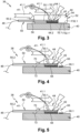
figure 2 est une représentation schématique d'un système de mesure d'au moins une grandeur thermique illustrant un mode de réalisation de l'invention, - La
figure 3 est une représentation schématique d'un système de mesure d'au moins une grandeur thermique illustrant un autre mode de réalisation de l'invention, - La
figure 4 est une représentation schématique d'un système de mesure d'au moins une grandeur thermique illustrant un autre mode de réalisation de l'invention, et - La
figure 5 est une représentation schématique d'un système de mesure d'au moins une grandeur thermique illustrant un autre mode de réalisation de l'invention. - Selon un mode de réalisation visible sur la
figure 1 , un aéronef comprend au moins un ensemble de propulsion 10 comportant une motorisation 12, une nacelle 14 positionnée autour de la motorisation 12 ainsi qu'un conduit annulaire 16 situé entre la motorisation 12 et la nacelle 14. - La motorisation 12 comprend, de l'avant vers l'arrière, une soufflante 18, un coeur de moteur 20 délimité par une enveloppe 20.1, une paroi externe 22 entourant le coeur de moteur 20, distante de son enveloppe 20.1, ainsi qu'une première tuyère 24 prolongeant le coeur de moteur 20. La paroi externe 22 est également appelée structure interne fixe ou IFS (pour Inner fixed structure en anglais). La motorisation 12 comprend une zone intermédiaire 26 (appelée core zone en anglais) positionnée entre l'enveloppe 20.1 du coeur de moteur 20 et la paroi externe 22.
- La nacelle 14 comprend une entrée d'air en amont de la motorisation 12, une partie intermédiaire destinée à entourer la soufflante, une partie arrière 28 pouvant intégrer des moyens d'inversion de poussée, positionnée autour de la paroi externe 22 et généralement terminée par une deuxième tuyère 30. La nacelle 14 présente également une paroi interne 32 (appelée Inner Fixed Structure en anglais) espacée de la motorisation 12, notamment de sa paroi externe 22.
- En fonctionnement, un flux primaire circule dans le coeur de moteur 20 et sort via la première tuyère 24. Un flux secondaire sortant de la soufflante 18 circule dans le conduit annulaire 16 délimité par la paroi externe 22 de la motorisation 12 et la paroi interne 32 de la nacelle 14. Les flux primaire et secondaire sont éjectés via les première et deuxième tuyères 24, 30. La paroi externe 22 de la motorisation 12 sépare une zone chaude à l'intérieur de la motorisation 12, dans la zone intermédiaire 26, et une zone froide à l'extérieur de la motorisation 12, dans le conduit annulaire 16. Selon un agencement, l'ensemble de propulsion 10 comprend au moins un équipement 34 positionné dans cette zone intermédiaire 26.
- Selon un mode de réalisation, l'ensemble de propulsion 10 comprend au moins un élément de protection thermique 36 comme un système de refroidissement par convection configuré pour ventiler la zone intermédiaire 26 et envoyer de l'air froid de la zone froide vers la zone chaude et/ou un écran thermique pour limiter l'impact des transferts thermiques par rayonnement sur l'équipement 34. Cet écran thermique peut être fixé directement sur l'équipement 34 ou sur l'enveloppe 20.1 du coeur de moteur 20. Il peut être positionné au niveau de différentes zones de l'ensemble de propulsion 10.
- L'ensemble de propulsion 10, la motorisation 12 et la nacelle 14 ne sont pas plus décrits car ils peuvent être identiques à ceux de l'art antérieur. Quel que soit le mode de réalisation, l'ensemble de propulsion 10 comprend au moins un équipement 34 sensible aux températures élevées ainsi qu'au moins un élément de protection thermique 36.
- Comme illustré sur les
figures 2 à 5 , l'ensemble de propulsion 10 comprend au moins un système de mesure 38 d'au moins une grandeur thermique, ladite grandeur thermique étant choisie parmi notamment une température, un flux thermique par rayonnement. Ce système de mesure 38 est relié à une structure 40 solidaire de l'ensemble de propulsion 10 et positionné dans un environnement 41, notamment un environnement convectif, présentant un flux d'air 41.1 matérialisé par des flèches. Ce flux d'air 41.1 peut véhiculer au moins un flux thermique par convection complexe dans trois dimensions. Par structure 40, on entend une structure, la peau d'une structure, un équipement ou tout autre élément de l'ensemble de propulsion 10. - Ce système de mesure 38 comprend au moins un capteur thermique 42 configuré pour déterminer au moins une grandeur thermique ainsi qu'au moins une barrière 44 transparente aux rayonnements infrarouges dans au moins une zone de ladite barrière 44, ladite barrière 44 étant configurée pour isoler le capteur thermique 42 du flux d'air 41.1. Cette barrière 44 permet de protéger le capteur thermique 42 d'éventuels polluants et/ou de flux thermiques par convection véhiculés notamment par le flux d'air 41.1 et de limiter l'impact de ces derniers sur la mesure de chaque grandeur par le capteur thermique 42.
- Selon une configuration, le capteur thermique 42 est un thermocouple, une thermistance ou un capteur de flux thermique. Selon un mode de réalisation, le capteur thermique 42 est configuré pour convertir une première grandeur physique comme la température ou un flux thermique en une deuxième grandeur physique comme un courant électrique. Le système de mesure 38 comprend au moins un système d'analyse 46 distant du capteur thermique 42 ainsi qu'au moins un câble électrique 48 reliant le capteur thermique 42 et le système d'analyse 46. Pour la présente demande, les rayons infrarouges présentent des longueurs d'onde comprises entre 0,7 µm et 12 µm.
- Selon un mode de réalisation, la barrière 44 est réalisée en un matériau configuré pour transmettre au moins 80% des rayons infrarouges. Le matériau de la barrière 44 présente une faible conductivité thermique inférieure ou égale à 1,5 W/m.K. Selon une configuration, la barrière 44 présente une transmittance (ou coefficient de transmission) la plus élevée possible, supérieure ou égale à 80%, de préférence supérieure ou égale à 90% et la plus proche de 100%, pour des rayons présentant une longueur d'ondes comprise entre 0,7 µm et 12 µm correspondant aux rayonnements infrarouges.
- Le matériau de la barrière 44 est choisi parmi les matériaux suivants : une vitrocéramique transparente comme SriAljSkO8, CaF2, AION, GaiGejSk TeiNbjBik , KBr, BaO-GeO2-Ga2O3, un polycarbonate, Tei-Asj-Gek, CaLa2S4, un verre de type BK7, un quartz Q2, un zinc selenide, ... Cette liste de matériaux n'est pas exhaustive.
- Selon une configuration, la barrière 44 présente une épaisseur inférieure ou égale à 1 mm.
- Selon un mode de réalisation visible sur les
figures 2 à 5 , le système de mesure 38 comprend au moins une gaine 50 qui s'étend entre des première et deuxième extrémités 50.1, 50.2, le capteur thermique 42 étant fixé à la première extrémité 50.1, la gaine 50 traversant la barrière 44. Cette gaine 50 est plus ou moins rigide. Lorsqu'elle est rigide, elle peut assurer la fonction de support configuré pour supporter le capteur thermique 42 et la barrière 44. Chaque câble électrique 48 chemine dans la gaine 50. Cette dernière est généralement isolée électriquement. - Selon des modes de réalisation visibles sur les
figures 2 et3 , la barrière 44 forme une enveloppe fermée 52, entourant le capteur thermique 42, délimitant une cavité 54 dans laquelle est positionné le capteur thermique 42. Selon un agencement, l'enveloppe fermée 52 est cylindrique. Bien entendu, l'invention n'est pas limitée à cette forme géométrique. Selon une configuration, la cavité 54 est mise au vide ou contient un gaz inerte. Selon une configuration, la barrière 44 formée par l'enveloppe fermée 52 comprend un orifice 56 configuré pour permettre à la gaine 50 de la traverser. En complément, le système de mesure 38 comprend au moins un système d'étanchéité 58 reliant la gaine 50 et la barrière 44 au droit de l'orifice 56 de manière à fermer la cavité 54 de manière étanche. - Selon un mode de réalisation visible sur la
figure 2 , l'enveloppe fermée 52 est distante de la structure 40. Selon ce mode de réalisation, la gaine 50 assure la fonction de support et sa deuxième extrémité 50.2 est reliée à la structure 40. A cet effet, le système de mesure 38 comprend au moins un élément de liaison 60 reliant la gaine 50 et la structure 40, comme de la colle, du mastic, au moins un rivet, au moins un boulon, au moins une vis ou autre. - Selon un agencement, la structure 40, la gaine 50 et/ou l'élément de liaison 60 est (ou sont) réalisé(s) en un matériau à faible conductivité thermique. Cette solution permet de filtrer les flux thermiques en ne laissant pas passer les flux thermiques par conduction entre la structure 40 et le capteur thermique 42.
- Selon un mode de réalisation, le système de mesure 38 comprend un élément de liaison 62 en un matériau à faible conductivité thermique pour relier d'une part l'enveloppe fermée 52 et d'autre part la gaine 50 et/ou le capteur thermique 42. Cette solution permet de filtrer les flux thermiques en isolant le capteur thermique 42 des flux thermiques par conduction à travers les fils 48 et la gaine 50.
- Selon le mode de réalisation visible sur la
figure 2 , l'enveloppe fermée 52 est entièrement réalisée en un matériau transparent aux rayonnements infrarouges. Cette enveloppe fermée 52 permet de filtrer les flux thermiques en ne laissant passer que les flux thermiques par rayonnement et en isolant le capteur thermique 42 des flux thermiques par convection. Le capteur thermique 42 étant isolé sur le plan de la conduction thermique de l'enveloppe fermée 52, il n'est pas impacté par les flux thermiques par conduction. - Selon un autre mode de réalisation visible sur la
figure 3 , l'enveloppe fermée 52 comprend au moins une première partie 52.1 qui présente une face intérieure F52.1 orientée vers le capteur thermique 42 positionné dans l'enveloppe fermée 52 et une face extérieure F52.1' orientée vers la structure 40. La première partie 52.1 est conformée comme la structure 40 de manière à épouser ses formes et à être intimement plaquée contre ladite structure 40. Ainsi, la première partie 52.1 de l'enveloppe fermée 52 est intercalée entre la structure 40 et le capteur thermique 42. - Selon le mode de réalisation visible sur la
figure 3 , l'enveloppe fermée 52 est en contact avec la structure 40. Le système de mesure 38 comprend une première interface 64.1 reliant le capteur thermique 42 et la face intérieure F52.1 ainsi qu'une deuxième interface 64.2 reliant la structure 40 et la face extérieure F52.1', les première et deuxième interfaces 64.1, 64.2 présentant une conductivité élevée de manière à ne pas filtrer les flux thermiques par conduction entre la structure 40 et le capteur thermique 42. - Selon un agencement, les première et deuxième interfaces 64.1, 64.2 présentent une épaisseur inférieure ou égale à 0,2 mm. A titre d'exemple, les première et deuxième interfaces 64.1, 64.2 sont obtenues par collage en utilisant une colle présentant une conductivité thermique assez élevée et supérieure ou égale à 0,2 W/m.K. Bien entendu, l'invention n'est pas limitée à ce mode de réalisation pour les première et deuxième interfaces 64.1, 64.2. Selon une première configuration, contrairement au mode de réalisation visible sur la
figure 2 , l'enveloppe fermée 52 n'est pas réalisée dans un même matériau transparent aux rayonnements infrarouges. La partie 52.1 est réalisée en un premier matériau présentant une conductivité thermique élevée alors que le reste de l'enveloppe fermée 52, appelé deuxième partie 52.2, est réalisée en un matériau transparent aux rayonnements infrarouges, à faible conductivité thermique. Selon une variante, la première partie 52.1 est réalisée en un matériau opaque aux rayonnements infrarouges, ayant une émissivité pour les rayonnements infrarouges proche de ou égale à celle du matériau de la structure 40. Lorsque le système de mesure 38 peut être impacté par les rayons solaires, la deuxième partie 52.2 peut être réalisée en un matériau filtrant les rayons solaires mais laissant passer les rayonnements infrarouges. Selon une deuxième configuration, l'enveloppe fermée 52 est réalisée dans sa totalité en un matériau transparent aux rayonnements infrarouges et au moins une face parmi les faces intérieure et extérieure F52.1, F52.1' de la partie 52.1 est recouverte d'un revêtement opaque aux rayonnements infrarouges, ledit revêtement étant réalisé en un matériau ayant une émissivité pour les rayonnements infrarouges proche de ou égale à celle du matériau de la structure 40. Selon les première et deuxième configurations, la partie 52.1 de l'enveloppe fermée 52 est configurée pour être opaque aux rayonnements infrarouges et avoir une émissivité pour les rayonnements infrarouges proche de ou égale à celle du matériau de la structure 40. - Le mode de réalisation visible sur la
figure 3 permet de réduire le gradient de température entre la structure 40 et le capteur thermique 42. Il est plus particulièrement adapté pour mesurer la température d'une zone en surface de la structure 40 positionnée au droit du capteur thermique 42 ou pour mesurer un flux thermique échangé par une zone en surface de la structure 40 positionnée au droit du capteur thermique 42. - Selon les modes de réalisation visibles sur les
figures 2 et3 , le capteur thermique 42 relié à la gaine 50 est introduit dans l'enveloppe fermée 52. Selon le mode de réalisation visible sur lafigure 3 , le capteur thermique 42 est relié à l'enveloppe fermée 52. Après la mise au vide ou le remplissage de l'enveloppe fermée 52 avec un gaz inerte, le système d'étanchéité 58 est mis en place de manière à fermer la cavité 54 de manière étanche. En suivant, la gaine 50 est reliée à la structure 40 selon le mode de réalisation visible sur lafigure 2 ou l'enveloppe fermée 52 est reliée à la structure 40 selon le mode de réalisation visible sur lafigure 3 . Selon des modes de réalisation visibles sur lesfigures 4 et 5 , la barrière 44 forme une coque 66 qui présente une périphérie 66.1 reliée de manière étanche à la structure 40 de sorte à délimiter une cavité 54 étanche dans laquelle est positionné le capteur thermique 42. Selon un agencement, la coque 66 présente une forme demi-sphérique. Bien entendu, l'invention n'est pas limitée à cette forme pour la coque 66. - Selon une configuration, le système de mesure 38 comprend au moins une liaison 68 reliant le capteur thermique 42 et la structure 40, la barrière 44 n'étant pas intercalée entre le capteur thermique 42 et la structure 40. Selon un agencement, cette liaison 68 est conductrice thermiquement.
- Selon une configuration, la barrière 44 formée par la coque 66 comprend un orifice 70 configuré pour permettre à la gaine 50 de la traverser. En complément, le système de mesure 38 comprend au moins un système d'étanchéité 72 reliant la gaine 50 et la barrière 44 au droit de l'orifice 70 de manière à fermer la cavité 54 de manière étanche.
- Selon un mode de réalisation visible sur la
figure 4 , la coque 66 est réalisée en un matériau transparent aux rayonnements infrarouges, ce matériau étant non poreux. - Selon ce mode de réalisation, après la fixation du capteur thermique 42 sur la structure 40, la coque 66 est reliée à la structure 40 dans une atmosphère contrôlée de manière à ce que l'air emprisonné entre la coque 66 et la structure 40 présente un faible taux d'hygrométrie et un faible niveau de polluants à pression atmosphérique au sol.
- Selon un mode de réalisation visible sur la
figure 5 , la coque 66 est perméable aux liquides tout en réduisant drastiquement l'effet de la convection avec l'air de la zone située à l'extérieur de la barrière 44. Cette solution permet d'obtenir une barrière 44 drainante permettant l'évacuation d'éventuels liquides présents dans la cavité 54. - Selon une configuration, la coque 66 comprend une unique couche réalisée en un matériau poreux ou nanoporeux, transparent aux rayonnements infrarouges. Selon une autre configuration, la coque 66 comprend une première couche perforée réalisée en un matériau transparent aux rayonnements infrarouges ainsi qu'une deuxième couche recouvrant la première couche, réalisée en un matériau poreux ou nanoporeux, transparent aux rayonnements infrarouges.
- A titre d'exemple, la coque 66 est réalisée en verre nanostructuré revêtu de SiO2 ou d'ITO, en polycarbonate revêtu d'AR ou en matériau nanoporeux comme la vitrocéramique de chalcogénures. Cette liste n'est pas exhaustive.
- Quel que soit le mode de réalisation, le système de mesure 38 d'au moins une grandeur thermique est configuré pour être relié à une structure 40 et positionné dans au moins un flux thermique par convection. Il comprend au moins un capteur thermique 42 ainsi qu'au moins une barrière 44 transparente aux rayonnements infrarouges dans au moins une zone de ladite barrière 44, la barrière 44 délimitant au moins partiellement une cavité 54 dans laquelle est positionné le capteur thermique 42. Cette solution permet de filtrer les flux thermiques impactant le capteur thermique 42 et de le protéger au moins des flux thermiques par convection. Le capteur thermique 42 est choisi parmi les capteurs thermiques de conception simple et fiable.
- Selon une configuration, la cavité 54 contient une atmosphère contrôlée présentant au moins une caractéristique parmi un niveau de vide élevé, un taux de remplissage en gaz inerte élevé, un faible taux d'hygrométrie et un faible niveau de polluants.
- Selon un premier mode de réalisation, le capteur thermique 42 est distant d'une structure 40 de l'ensemble de propulsion 10 et isolé de cette dernière sur le plan des flux thermiques par conduction. Selon ce premier mode de réalisation, le capteur thermique est impacté par les flux thermiques par rayonnement et protégé des flux thermiques par convection et par conduction. Ce mode de réalisation est plus particulièrement adapté pour déterminer précisément l'impact des flux thermiques par rayonnement en un point donné de l'ensemble de propulsion 10 distant de la structure 40, en limitant les perturbations liées à d'éventuels polluants et/ou aux flux thermiques par convection et par conduction.
- Selon d'autres modes de réalisation, le capteur thermique 42 est accolé à une structure 40 d'un ensemble de propulsion 10 et relié à cette dernière par au moins un élément à conductivité thermique élevée limitant l'apparition d'un gradient thermique entre le capteur thermique 42 et la structure 40. Ce mode de réalisation est plus particulièrement adapté pour déterminer précisément la température ou le flux thermique échangé en un point donné à la surface de la structure 40, au droit duquel est positionné le capteur thermique 42, en limitant les perturbations liées à d'éventuels polluants et/ou aux flux thermiques par convection. Bien entendu, l'invention n'est pas limitée aux modes de réalisation précédemment décrits. La barrière 44 peut avoir différentes formes (autres que cylindrique ou demi-sphérique). Quelque soit le mode de réalisation, contrairement à des systèmes de mesure de l'art antérieur qui comprennent une barrière sous la forme d'un hublot limitant les directions des rayonnements impactant le capteur thermique 42, la barrière 44 présente un facteur de forme supérieur ou égal à 0,8. Ainsi, le capteur thermique 42 peut recevoir des rayonnements provenant d'une multitude de directions et d'un plus grand angle solide par rapport aux solutions de l'art antérieur.
Claims (13)
- Système de mesure (38) d'au moins une grandeur thermique, le système de mesure (38) étant configuré pour être relié à une structure (40) et comprenant au moins un capteur thermique (42), caractérisé en ce que le système de mesure (38) comprend au moins une barrière (44) transparente aux rayonnements infrarouges dans au moins une zone de ladite barrière (44), la barrière (44) délimitant au moins partiellement une cavité (54) dans laquelle est positionné le capteur thermique (42) et présentant un facteur de forme supérieur ou égal à 0,8.
- Système de mesure (38) d'au moins une grandeur thermique selon la revendication précédente, caractérisé en ce que la cavité (54) contient une atmosphère contrôlée présentant au moins une caractéristique parmi un niveau de vide élevé, un taux de remplissage en gaz inerte élevé, un faible taux d'hygrométrie et un faible niveau de polluants.
- Système de mesure (38) d'au moins une grandeur thermique selon l'une des revendications précédentes, caractérisé en ce que la barrière (44) présente une transmittance supérieure ou égale à 80% pour des rayons présentant une longueur d'ondes comprise entre 0,7 µm et 12 µm.
- Système de mesure (38) d'au moins une grandeur thermique selon l'une des revendications précédentes, caractérisé en ce que la barrière (44) présente une épaisseur inférieure ou égale à 1 mm.
- Système de mesure (38) d'au moins une grandeur thermique selon l'une des revendications précédentes, caractérisé en ce que le système de mesure (38) comprend une gaine (50) qui s'étend entre des première et deuxième extrémités (50.1, 50.2), le capteur thermique (42) étant fixé à la première extrémité (50.1), en ce que la barrière (44) comprend un orifice (56, 70) configuré pour permettre à la gaine (50) de la traverser et en ce que le système de mesure (38) comprend au moins un système d'étanchéité (58, 72) reliant la gaine (50) et la barrière (44) au droit de l'orifice (56).
- Système de mesure (38) d'au moins une grandeur thermique selon l'une des revendications précédentes, caractérisé en ce que le capteur thermique (42) est accolé à la structure (40) et relié à cette dernière par au moins un élément à conductivité thermique élevée.
- Système de mesure (38) d'au moins une grandeur thermique selon la revendication précédente, caractérisé en ce que la barrière (44) forme une coque (66) qui présente une périphérie (66.1) reliée de manière étanche à la structure (40) de sorte à délimiter la cavité (54) dans laquelle est positionné le capteur thermique (42).
- Système de mesure (38) d'au moins une grandeur thermique selon la revendication précédente, caractérisé en ce que la coque (66) comprend au moins une couche réalisée en un matériau poreux ou nanoporeux, transparent aux rayonnements infrarouges.
- Système de mesure (38) d'au moins une grandeur thermique selon l'une des revendications 1 à 5, caractérisé en ce que la barrière (44) forme une enveloppe fermée (52) entourant le capteur thermique (42) et délimitant la cavité (54) dans laquelle est positionné le capteur thermique (42).
- Système de mesure (38) d'au moins une grandeur thermique selon la revendication précédente, caractérisé en ce que le capteur thermique (42) est distant de la structure (40) et isolé de cette dernière en matière de flux thermique par conduction.
- Système de mesure (38) d'au moins une grandeur thermique selon la revendication 9, caractérisé en ce que l'enveloppe fermée (52) comprend au moins une première partie (52.1) qui présente une face intérieure (F52.1) orientée vers le capteur thermique (42) positionné dans l'enveloppe fermée (52) et une face extérieure (F52.1') orientée vers la structure (40), en ce que le système de mesure (38) comprend une première interface (64.1) reliant le capteur thermique (42) et la face intérieure (F52.1) ainsi qu'une deuxième interface (64.2) reliant la structure (40) et la face extérieure (F52.1'), les première et deuxième interfaces (64.1, 64.2) présentant une conductivité élevée et en ce que la première partie (52.1) de l'enveloppe fermée (52) est réalisée en un matériau présentant une conductivité thermique élevée.
- Système de mesure (38) d'au moins une grandeur thermique selon la revendication précédente, caractérisé en ce que la première partie (52.1) de l'enveloppe fermée (52) est configurée pour être opaque aux rayonnements infrarouges et avoir une émissivité pour les rayonnements infrarouges proche de ou égale à celle du matériau de la structure (40).
- Ensemble de propulsion d'aéronef comportant au moins un système de mesure (38) d'au moins une grandeur thermique selon l'une des revendications précédentes.
Applications Claiming Priority (1)
| Application Number | Priority Date | Filing Date | Title |
|---|---|---|---|
| FR2303946 | 2023-04-20 |
Publications (1)
| Publication Number | Publication Date |
|---|---|
| EP4450936A1 true EP4450936A1 (fr) | 2024-10-23 |
Family
ID=87800883
Family Applications (1)
| Application Number | Title | Priority Date | Filing Date |
|---|---|---|---|
| EP24170255.4A Pending EP4450936A1 (fr) | 2023-04-20 | 2024-04-15 | Système de mesure d'au moins une grandeur thermique configuré pour limiter l'impact des transferts thermiques par convection |
Country Status (3)
| Country | Link |
|---|---|
| US (1) | US20240353269A1 (fr) |
| EP (1) | EP4450936A1 (fr) |
| CN (1) | CN118817078A (fr) |
Citations (3)
| Publication number | Priority date | Publication date | Assignee | Title |
|---|---|---|---|---|
| FR2046303A5 (fr) * | 1969-04-21 | 1971-03-05 | Gen Electric | |
| US5655839A (en) * | 1994-06-16 | 1997-08-12 | Raytek Sensorik Gmbh | IR temperature sensor |
| EP1835270A1 (fr) * | 2006-03-15 | 2007-09-19 | Siemens Aktiengesellschaft | Capteur de température destiné à une turbine |
Family Cites Families (11)
| Publication number | Priority date | Publication date | Assignee | Title |
|---|---|---|---|---|
| US4136518A (en) * | 1972-05-03 | 1979-01-30 | Avco Corporation | Infrared radiation suppressor for a gas turbine engine |
| US4800715A (en) * | 1981-08-10 | 1989-01-31 | The United States Of America As Represented By The Secretary Of The Army | Apparatus for suppressing infrared radiation emitted from gas turbine engines |
| US6253540B1 (en) * | 1982-07-08 | 2001-07-03 | General Electric Company | Removable baffle infrared suppressor |
| DE3712328A1 (de) * | 1987-04-11 | 1988-10-27 | Messerschmitt Boelkow Blohm | Einrichtung zur infrarotstrahlungsabschirmung |
| US20020122459A1 (en) * | 2000-12-27 | 2002-09-05 | Mcfarland Dawn Key | Passively cooled high temperature capable probe housing |
| US20040136434A1 (en) * | 2003-01-13 | 2004-07-15 | Langley Lawrence W. | Laminated heat flux indicating device |
| CA2739494A1 (fr) * | 2008-09-23 | 2010-04-08 | Aerovironment Inc. | Reservoir pour liquide cryogenique |
| US9228902B2 (en) * | 2010-07-08 | 2016-01-05 | Cvg Management Corporation | Infrared temperature measurement and stabilization thereof |
| US10830132B2 (en) * | 2016-04-29 | 2020-11-10 | General Electric Company | Micro thermal imaging system for turbine engines |
| US10829226B2 (en) * | 2016-05-24 | 2020-11-10 | Textron Innovations, Inc. | Compressor temperature control system and method |
| FR3059419B1 (fr) * | 2016-11-29 | 2018-11-23 | Airbus Operations (S.A.S.) | Systeme de protection d'un thermocouple installe dans un compartiment de moteur d'aeronef |
-
2024
- 2024-04-15 EP EP24170255.4A patent/EP4450936A1/fr active Pending
- 2024-04-16 CN CN202410456510.3A patent/CN118817078A/zh active Pending
- 2024-04-17 US US18/637,736 patent/US20240353269A1/en active Pending
Patent Citations (3)
| Publication number | Priority date | Publication date | Assignee | Title |
|---|---|---|---|---|
| FR2046303A5 (fr) * | 1969-04-21 | 1971-03-05 | Gen Electric | |
| US5655839A (en) * | 1994-06-16 | 1997-08-12 | Raytek Sensorik Gmbh | IR temperature sensor |
| EP1835270A1 (fr) * | 2006-03-15 | 2007-09-19 | Siemens Aktiengesellschaft | Capteur de température destiné à une turbine |
Non-Patent Citations (1)
| Title |
|---|
| KUCHH NAYA SIKHO: "Thermopile | Working Principle | THE INSTRUMENT GURU", 22 October 2021 (2021-10-22), pages 1 - 8, XP093101005, Retrieved from the Internet <URL:https://web.archive.org/web/20211022041155/https://theinstrumentguru.com/thermopile/> [retrieved on 20231114] * |
Also Published As
| Publication number | Publication date |
|---|---|
| CN118817078A (zh) | 2024-10-22 |
| US20240353269A1 (en) | 2024-10-24 |
Similar Documents
| Publication | Publication Date | Title |
|---|---|---|
| AU1866595A (en) | Noncontact active temperature sensor | |
| EP2880451B1 (fr) | Système de sonde, sonde mixte de référence primaire pour aéronef, aéronef et procédé de mesure associés | |
| FR3015431A1 (fr) | Structure primaire de mat d'accrochage renforcee. | |
| WO2010089487A1 (fr) | Ensemble de suspension pour turboréacteur d'aéronef | |
| EP1035017A1 (fr) | Procédé de simulation des flux thermiques externes absorbés en vol par les éléments radiatifs extérieurs d'un engin spatial et engin spatial pour la mise en oeuvre de ce procédé | |
| CA2645240C (fr) | Tuyere de soufflante a section reglable | |
| FR2990754A1 (fr) | Dispositif de mesure des amplitudes vibratoires des sommets d'aubes dans une turbomachine | |
| EP2742344A1 (fr) | Capteur de gaz d'échappement pour un moteur a combustion interne | |
| EP1721136B1 (fr) | Procede de realisation d'un dispositif pour la detection thermique d'un rayonnement comportant un microbolometre actif et un microbolometre passif | |
| WO2021019139A1 (fr) | Capot pour vehicule, en particulier pour vehicule supersonique ou hypersonique | |
| EP4450936A1 (fr) | Système de mesure d'au moins une grandeur thermique configuré pour limiter l'impact des transferts thermiques par convection | |
| US20080149861A1 (en) | Low-temperature adjustable blackbody apparatus | |
| FR3069707B1 (fr) | Dispositif infrarouge | |
| EP0100694A1 (fr) | Câble isolé pour le transport d'énergie électrique notamment à haute tension, et dispositif de détection de défauts dans un tel câble | |
| EP3839457B1 (fr) | Groupe propulseur d'aéronef présentant une entrée d'air présentant une paroi munie d'un dispositif de mesure à capteur optique entouré par une enveloppe souple accolée à la dite paroi et procédé d'installation dudit dispositif | |
| EP1144966B1 (fr) | Detecteur thermique a angle de vue limite | |
| EP4530589B1 (fr) | Dispositif de mesure de temperature a fibre optique isolee d'une paroi de fixation par une piece comprenant du liege | |
| EP1510800B1 (fr) | Procédé de compensation des effets des flux par rayonnement sur un capteur de temperature | |
| EP3286535A1 (fr) | Capteur hautes temperatures avec connecteur integre | |
| EP2204981B1 (fr) | Procédé d'évaluation de salissure différentielle | |
| FR2958449A1 (fr) | Dispositif de controle thermique d'un tube a collecteur rayonnant | |
| WO1995035643A1 (fr) | Four electrique de cuisson | |
| FR3059419A1 (fr) | Systeme de protection d'un thermocouple installe dans un compartiment de moteur d'aeronef | |
| EP0250281B1 (fr) | Capteur de mesure de la temperature de surface d'un corps | |
| FR2933772A1 (fr) | Dispositif de mesure de la temperature d'une enceinte |
Legal Events
| Date | Code | Title | Description |
|---|---|---|---|
| PUAI | Public reference made under article 153(3) epc to a published international application that has entered the european phase |
Free format text: ORIGINAL CODE: 0009012 |
|
| STAA | Information on the status of an ep patent application or granted ep patent |
Free format text: STATUS: THE APPLICATION HAS BEEN PUBLISHED |
|
| AK | Designated contracting states |
Kind code of ref document: A1 Designated state(s): AL AT BE BG CH CY CZ DE DK EE ES FI FR GB GR HR HU IE IS IT LI LT LU LV MC ME MK MT NL NO PL PT RO RS SE SI SK SM TR |
|
| STAA | Information on the status of an ep patent application or granted ep patent |
Free format text: STATUS: REQUEST FOR EXAMINATION WAS MADE |
|
| 17P | Request for examination filed |
Effective date: 20250414 |
|
| STAA | Information on the status of an ep patent application or granted ep patent |
Free format text: STATUS: EXAMINATION IS IN PROGRESS |
|
| 17Q | First examination report despatched |
Effective date: 20260319 |