EP4450889A1 - Ventilation system - Google Patents
Ventilation system Download PDFInfo
- Publication number
- EP4450889A1 EP4450889A1 EP22907015.6A EP22907015A EP4450889A1 EP 4450889 A1 EP4450889 A1 EP 4450889A1 EP 22907015 A EP22907015 A EP 22907015A EP 4450889 A1 EP4450889 A1 EP 4450889A1
- Authority
- EP
- European Patent Office
- Prior art keywords
- air supply
- airflow
- exhaust
- supply
- fan
- Prior art date
- Legal status (The legal status is an assumption and is not a legal conclusion. Google has not performed a legal analysis and makes no representation as to the accuracy of the status listed.)
- Granted
Links
Images





Classifications
-
- F—MECHANICAL ENGINEERING; LIGHTING; HEATING; WEAPONS; BLASTING
- F24—HEATING; RANGES; VENTILATING
- F24F—AIR-CONDITIONING; AIR-HUMIDIFICATION; VENTILATION; USE OF AIR CURRENTS FOR SCREENING
- F24F11/00—Control or safety arrangements
- F24F11/70—Control systems characterised by their outputs; Constructional details thereof
- F24F11/72—Control systems characterised by their outputs; Constructional details thereof for controlling the supply of treated air, e.g. its pressure
- F24F11/74—Control systems characterised by their outputs; Constructional details thereof for controlling the supply of treated air, e.g. its pressure for controlling air flow rate or air velocity
- F24F11/77—Control systems characterised by their outputs; Constructional details thereof for controlling the supply of treated air, e.g. its pressure for controlling air flow rate or air velocity by controlling the speed of ventilators
-
- F—MECHANICAL ENGINEERING; LIGHTING; HEATING; WEAPONS; BLASTING
- F24—HEATING; RANGES; VENTILATING
- F24F—AIR-CONDITIONING; AIR-HUMIDIFICATION; VENTILATION; USE OF AIR CURRENTS FOR SCREENING
- F24F7/00—Ventilation
- F24F7/007—Ventilation with forced flow
-
- F—MECHANICAL ENGINEERING; LIGHTING; HEATING; WEAPONS; BLASTING
- F24—HEATING; RANGES; VENTILATING
- F24F—AIR-CONDITIONING; AIR-HUMIDIFICATION; VENTILATION; USE OF AIR CURRENTS FOR SCREENING
- F24F2110/00—Control inputs relating to air properties
- F24F2110/10—Temperature
- F24F2110/12—Temperature of the outside air
-
- F—MECHANICAL ENGINEERING; LIGHTING; HEATING; WEAPONS; BLASTING
- F24—HEATING; RANGES; VENTILATING
- F24F—AIR-CONDITIONING; AIR-HUMIDIFICATION; VENTILATION; USE OF AIR CURRENTS FOR SCREENING
- F24F2110/00—Control inputs relating to air properties
- F24F2110/50—Air quality properties
- F24F2110/65—Concentration of specific substances or contaminants
- F24F2110/70—Carbon dioxide
-
- F—MECHANICAL ENGINEERING; LIGHTING; HEATING; WEAPONS; BLASTING
- F24—HEATING; RANGES; VENTILATING
- F24F—AIR-CONDITIONING; AIR-HUMIDIFICATION; VENTILATION; USE OF AIR CURRENTS FOR SCREENING
- F24F2120/00—Control inputs relating to users or occupants
- F24F2120/10—Occupancy
-
- F—MECHANICAL ENGINEERING; LIGHTING; HEATING; WEAPONS; BLASTING
- F24—HEATING; RANGES; VENTILATING
- F24F—AIR-CONDITIONING; AIR-HUMIDIFICATION; VENTILATION; USE OF AIR CURRENTS FOR SCREENING
- F24F7/00—Ventilation
- F24F7/04—Ventilation with ducting systems, e.g. by double walls; with natural circulation
- F24F7/06—Ventilation with ducting systems, e.g. by double walls; with natural circulation with forced air circulation, e.g. by fan positioning of a ventilator in or against a conduit
- F24F7/08—Ventilation with ducting systems, e.g. by double walls; with natural circulation with forced air circulation, e.g. by fan positioning of a ventilator in or against a conduit with separate ducts for supplied and exhausted air with provisions for reversal of the input and output systems
-
- Y—GENERAL TAGGING OF NEW TECHNOLOGICAL DEVELOPMENTS; GENERAL TAGGING OF CROSS-SECTIONAL TECHNOLOGIES SPANNING OVER SEVERAL SECTIONS OF THE IPC; TECHNICAL SUBJECTS COVERED BY FORMER USPC CROSS-REFERENCE ART COLLECTIONS [XRACs] AND DIGESTS
- Y02—TECHNOLOGIES OR APPLICATIONS FOR MITIGATION OR ADAPTATION AGAINST CLIMATE CHANGE
- Y02B—CLIMATE CHANGE MITIGATION TECHNOLOGIES RELATED TO BUILDINGS, e.g. HOUSING, HOUSE APPLIANCES OR RELATED END-USER APPLICATIONS
- Y02B30/00—Energy efficient heating, ventilation or air conditioning [HVAC]
- Y02B30/70—Efficient control or regulation technologies, e.g. for control of refrigerant flow, motor or heating
Definitions
- the present disclosure relates to a ventilation system.
- Patent Literature 1 discloses a ventilation system (heat recovery outdoor air conditioning system) capable of first type ventilation.
- This ventilation system includes a heat exchanger, a supply air path and exhaust air path that allow the inside and outside of a target space to communicate with each other via the heat exchanger, an air supply fan that supplies air outside the target space to the target space via the supply air path, and an exhaust fan that exhausts air in the target space to the outside of the target space via the exhaust air path.
- the heat exchanger of a heat pump outdoor air conditioner recovers heat from the return air in the indoor zone and then exhausts the heat to the outdoors, and uses the recovered heat for heat exchange with outside air from outdoors to supply the air to the indoor zone.
- PATENT LITERATURE 1 Japanese Laid-Open Patent Publication No. 03-20573
- the conventional ventilation system is configured by the air supply fan, the exhaust fan, and the heat exchanger being housed in a single casing, it is not assumed, for example, to supply the supply air subjected to a heat exchange to a plurality of areas or to adjust the amount of supply air for each of the plurality of areas.
- An object of the present disclosure is to provide a ventilation system capable of supplying supply air subjected to a heat exchange to a plurality of areas in an airflow adjustable manner.
- the first heat exchanger and the first air supply fan and second air supply fan located further toward an indoor side than the first heat exchanger are included in the interior of the air supply path, so that the supply air subjected to a heat exchange can be supplied to the plurality of areas.
- control unit executes the first air supply control and the second air supply control, it is possible to adjust each of the first supply airflow and the second supply airflow.
- the supply air subjected to a heat exchange can be supplied to the plurality of areas in an airflow adjustable manner.
- the control unit may determine the target value of the first supply airflow and the target value of the second supply airflow on the basis of a detection result of the monitoring sensor.
- control unit determines the target value of the first supply airflow and the target value of the second supply airflow on the basis of the detection result of the monitoring sensor, ventilation contributing to the improvement of the indoor environment (for example, ventilation that decreases the CO2 concentration) can be performed for each area.
- the control unit may execute exhaust control to adjust a rotational speed of the exhaust fan so that the exhaust airflow becomes a target value.
- the exhaust airflow can be adjusted.
- appropriate ventilation can be performed by balancing the sum of the first supply airflow and the second supply airflow with the exhaust airflow.
- control unit may determine the target value of the exhaust airflow and a controlled variable for the refrigerant circuit on the basis of the target value of the first supply airflow and the target value of the second supply airflow.
- the control unit determines the target value of the exhaust airflow and a controlled variable for the refrigerant circuit on the basis of the target value of the first supply airflow and the target value of the second supply airflow, for example, the refrigerant circuit can be controlled with an appropriate heat recovery amount while balancing the sum of the first supply airflow and the second supply airflow with the exhaust airflow.
- the control unit may include: a main controller that determines the target value of the first supply airflow, the target value of the second supply airflow, the target value of the exhaust airflow, and the controlled variable for the refrigerant circuit; a first controller that executes the first air supply control; a second controller that executes the second air supply control; and a third controller that executes the exhaust control.
- the first to third controllers adjust the fan speed based on the target value, and the main controller determines the target value of each airflow and the controlled variable for the refrigerant circuit, so that the processing load on the main controller can be suppressed as compared with the case where the main controller is responsible for all processing. Therefore, for example, the manufacturing cost of the ventilation system can be reduced by, for example, using a controller for an air conditioner as the main controller.
- the ventilation system according to the present disclosure may further include: a first air supply unit that includes the first air supply fan, the first air supply detector, and the first controller and is capable of autonomously adjusting the first supply airflow; and a second air supply unit that includes the second air supply fan, the second air supply detector, and the second controller and is capable of autonomously adjusting the second supply airflow.
- the first air supply unit and the second air supply unit can be placed in the same room or in different rooms, for example depending on user needs.
- the flexibility of the installation places of the air supply units is improved.
- the ventilation system according to the present disclosure may further include an exhaust unit that includes the exhaust fan, the exhaust detector, and the third controller and is capable of autonomously adjusting the exhaust airflow.
- the exhaust unit can be placed indoors or outdoors, for example depending on user needs.
- the flexibility of the installation place of the exhaust unit is improved.
- FIG. 1 is a longitudinal sectional view of a building illustrating an example of the overall configuration of a ventilation system 1.
- RA Indoor air (return air). This is also the air that the system 1 draws in from indoors.
- EA Air (exhaust air) that the system 1 discharges outdoors.
- the ventilation system 1 provides first-type ventilation for an indoor target space RM while performing temperature adjustment for the supply air SA and heat recovery from the return air RA.
- the target space RM is, for example, the indoor space of various buildings such as an office building, a hospital, and a factory.
- the target space RM is preferably an airtight room for a predetermined use, but may be, for example, an indoor corridor, a staircase, an entrance, or the like. Furthermore, in the target space RM, an indoor unit 2 of an air conditioning system separate from the ventilation system 1 may be installed.
- the ventilation system 1 includes a heat exchange unit 10 on the utilization side (air supply side), an air supply unit 20, a heat exchange unit 30 on the recovery side (exhaust side), an exhaust unit 40, a compressor unit 50, and a refrigerant circuit 60.
- the heat exchange unit 10 and the air supply unit 20 are installed in the ceiling space of the target space RM, and the heat exchange unit 30, the exhaust unit 40, and the compressor unit 50 are installed inside the wall of the target space RM.
- the ventilation system 1 further includes an input device 70 that is an input equipment allowing users to input operations, and a monitoring sensor 80.
- the input device 70 is, for example, a remote controller attached to the wall surface of the target space RM.
- the input device 70 may be installed in a room different from the target space RM, such as a management room (not illustrated).
- the monitoring sensor 80 monitors an indoor air state, and is capable of wired or wireless communication conforming to a predetermined communication standard.
- the monitoring sensor 80 is assumed to be a CO2 sensor that is attached to the ceiling surface of the target space RM and that detects CO2 concentration.
- each unit illustrated in FIG. 1 is an example, and for example, the heat exchange unit 30 and the exhaust unit 40 may be arranged in the ceiling space, and the return air RA may be drawn in from the ceiling side.
- At least one of the heat exchange unit 30, the exhaust unit 40, and the compressor unit 50 may be installed outdoors.
- the ventilation system 1 includes a plurality of (two in the illustrated example) air supply units 20 of the same product.
- one of the plurality of air supply units 20 is referred to as a first air supply unit 20A, and the other is referred to as a second air supply unit 20B.
- the ventilation system 1 includes a plurality of (two in the illustrated example) CO2 sensors 80 of the same product.
- one of the plurality of CO2 sensors 80 is referred to as a first CO2 sensor 80A, and the other is referred to as a second CO2 sensor 80B.
- the first CO2 sensor 80A satisfies the following installation condition 1
- the second CO2 sensor 80B satisfies the following installation condition 2.
- Installation Condition 1 The distance (for example, within 1 m) from the first CO2 sensor 80A to the first air supply unit 20A is shorter than the distance from the first CO2 sensor 80A to the second air supply unit 20B.
- Installation Condition 2 The distance (for example, within 1 m) from the second CO2 sensor 80B to the second air supply unit 20B is shorter than the distance from the second CO2 sensor 80B to the first air supply unit 20A.
- the heat exchange unit 10 on the utilization side has a casing 11 and a plurality of devices housed in the casing 11.
- the plurality of devices includes a utilization-side heat exchanger (hereinafter referred to as "first heat exchanger") 12, which is an element device of the refrigerant circuit 60, and an outside air temperature sensor 13.
- the first heat exchanger 12 is, for example, a cross-fin tube or microchannel heat exchanger, and exchanges heat between the refrigerant flowing inside the first heat exchanger 12 and the outside air OA.
- the first air supply unit 20A has a casing 21A and a plurality of devices housed in the casing 21A.
- the plurality of devices includes a first air supply fan 22A, a first air supply detector 23A, a first supply air temperature sensor 24A, and a first controller 25A.
- the first air supply fan 22A is, for example, a centrifugal fan with controllable fan speed.
- the first air supply detector 23A is, for example, an airflow sensor for detecting airflow, or a sensor for detecting air velocity, differential pressure, fan speed, or the like (hereinafter referred to as "airflow equivalent"), which are physical quantities from which the airflow is calculated. Therefore, if the first controller 25A has the function of counting the fan speed, the first controller 25A also serves as the first air supply detector 23A.
- the first controller 25A is, for example, a control module including a circuit board and an integrated circuit such as a central processing unit (CPU) and memory mounted on the circuit board.
- the integrated circuit may include at least a field-programmable gate array (FPGA) or an application-specific IC (ASIC).
- the first controller 25A is capable of communication control with other controllers and sensors conforming to a predetermined communication standard, and is capable of performing predetermined information processing such as control for adjusting the fan speed so that the airflow of the first air supply fan 22A becomes a target value.
- the second air supply unit 20B has a casing 21B and a plurality of devices housed in the casing 21B.
- the plurality of devices includes a second air supply fan 22B, a second air supply detector 23B, a second supply air temperature sensor 24B, and a second controller 25B.
- the second air supply fan 22B is, for example, a centrifugal fan with controllable fan speed.
- the second air supply detector 23B is, for example, an airflow sensor for detecting airflow or a sensor for detecting the airflow equivalent. Therefore, if the second controller 25B has the function of counting the fan speed, the second controller 25B also serves as the second air supply detector 23B.
- the second controller 25B is, for example, a control module including a circuit board and an integrated circuit such as a CPU and memory mounted on the circuit board.
- the integrated circuit may include at least the FPGA or the ASIC.
- the second controller 25B is capable of communication control with other controllers and sensors conforming to a predetermined communication standard, and is capable of performing predetermined information processing such as control for adjusting the fan speed so that the airflow of the second air supply fan 22B becomes a target value.
- the heat exchange unit 30 on the recovery side has a casing 31 and a plurality of devices housed in the casing 31.
- the plurality of devices includes a recovery-side heat exchanger (hereinafter referred to as "second heat exchanger") 32, which is an element device of the refrigerant circuit 60, and a return air temperature sensor 33.
- second heat exchanger recovery-side heat exchanger
- the second heat exchanger 32 is, for example, a cross-fin tube or microchannel heat exchanger, and exchanges heat between the refrigerant flowing inside the second heat exchanger 32 and the return air RA.
- the exhaust unit 40 has a casing 41 and a plurality of devices housed in the casing 41.
- the plurality of devices includes an exhaust fan 42, an exhaust detector 43, and a third controller 44.
- the exhaust fan 42 is, for example, a centrifugal fan with controllable fan speed.
- the exhaust detector 43 is, for example, an airflow sensor for detecting airflow or a sensor for detecting the airflow equivalent. Therefore, if the third controller 44 has the function of counting the fan speed, the third controller 44 also serves as the air supply detector 43.
- the third controller 44 is, for example, a control module including a circuit board and an integrated circuit such as a CPU and memory mounted on the circuit board.
- the integrated circuit may include at least the FPGA or the ASIC.
- the third controller 44 is capable of communication control with other controllers and sensors conforming to a predetermined communication standard, and is capable of performing predetermined information processing such as control for adjusting the fan speed so that the airflow of the exhaust fan 42 becomes a target value.
- the compressor unit 50 includes a casing 51 and a plurality of devices housed in the casing 51.
- the plurality of devices includes a compressor 52, a four-way valve 53, an expansion valve 54, and a main controller 55.
- the refrigerant circuit 60 circulates refrigerant through the compressor 52, the first heat exchanger 12, and the second heat exchanger 32, and has the compressor 52, the four-way valve 53, the expansion valve 54, the first heat exchanger 12, the second heat exchanger 32, and a refrigerant pipe 61 that connects these components.
- the main controller 55 is, for example, a control module including a circuit board and an integrated circuit such as a CPU and memory mounted on the circuit board.
- the integrated circuit may include at least the FPGA or the ASIC.
- the main controller 55 is capable of performing communication control with other controllers and sensors conforming to a predetermined communication standard and of performing predetermined information processing such as determination of a controlled variable for the refrigerant circuit 60 according to the ventilation rate.
- the suction port of the casing 11 communicates with an air supply port outdoors through a duct d1.
- the suction ports of the casings 21A and 21B are airtightly connected to the blow-out port of the casing 11 by a duct d2 being a branch pipe.
- the blow-out ports of the casings 21A and 21B are exposed from the ceiling surface to the target space RM.
- the air path formed by the duct d1, the casing 11, the duct d2, and the casings 21A and 21B connects the outdoor space to the indoor space, and constitutes an "air supply path" having an interior in which the first heat exchanger 12 and the first and second air supply fans 22A and 22B located further toward the indoor side than the first heat exchanger 12 are arranged.
- a blow-out unit having a filter, a wind direction plate, and the like may be coupled to the blow-out side of the casings 21A and 21B via a duct or directly, and the blow-out unit may be exposed from the ceiling surface to the target space RM.
- a humidifying unit or a filter unit (not illustrated) that collects microparticles (such as PM 2.5) may be provided at points on the ducts d1 and d2.
- the casing of each of the above units may also be a component of the air supply path.
- the suction port of the casing 31 is airtightly connected to the air supply port in the floor surface by a duct d3 including a branch pipe.
- the suction port of the casing 41 is airtightly connected to the blow-out port of the casing 31 by a duct d4.
- the blow-out port of the casing 41 communicates with an exhaust port outdoors through a duct d5.
- the air path formed by the duct d3, the casing 31, the duct d4, the casing 41, and the duct d5 connects the outdoors to the indoors, and constitutes an "exhaust air path" in which the second heat exchanger 32 and the exhaust fan 42 are disposed.
- the outside air temperature sensor 13 detects the temperature of the outside air OA before heat exchange with the first heat exchanger 12.
- the air subjected to heat exchange in the first heat exchanger 12 passes through the duct d2 and the casings 21A and 21B and is delivered indoors as the supply air SA.
- the first and second supply air temperature sensors 24A and 24B detect the temperature of the supply air SA.
- the return air temperature sensor 33 detects the temperature of the return air RA before heat exchange with the second heat exchanger 32.
- the air after the heat exchange with the second heat exchanger 32 passes through the casing 41 and the duct d5 and is delivered outdoors as the exhaust air EA.
- the exhaust air path may be configured such that the heat exchange unit 30 is located on the blow-out side (downstream side in the exhaust direction) of the exhaust unit 40.
- the heat exchange unit 30 and the exhaust unit 40 may be an integrated unit housed in the same casing.
- the compressor 52 is an element device of the refrigerant circuit 60, sucking in low-pressure gaseous refrigerant and discharging high-pressure gaseous refrigerant.
- the compressor 52 is, for example, a variable displacement type (variable capacity type), the displacement of which is variable by the inverter control of an electric motor.
- the compressor 52 may be of a constant-displacement type or two or more compressors 52 may be connected in parallel.
- the expansion valve 54 is, for example, an electric valve for adjusting the flow rate and pressure of the refrigerant in the pipe 61.
- the refrigerant pressure to the first heat exchanger 12 is adjusted by controlling the opening degree of the expansion valve 54.
- the four-way valve 53 reverses the flow direction of the refrigerant in the circuit, and switches the refrigerant discharged from compressor 52 to either first heat exchanger 12 or second heat exchanger 32. Therefore, the temperature adjustment operation that can be executed by the ventilation system 1 includes "cold air supply” in which the outside air OA is cooled and supplied indoors, and “warm air supply” in which the outside air OA is heated and supplied indoors.
- the four-way valve 53 is maintained in the state indicated by the solid line in FIG. 1 .
- the first heat exchanger 12 on the utilization side functions as an evaporator and cools the outside air OA
- the second heat exchanger 32 on the recovery side functions as a condenser and heats the return air RA.
- the heating of the return air RA corresponds to heat recovery from the return air RA.
- the four-way valve 53 is maintained in the state indicated by the broken line in FIG. 1 .
- the first heat exchanger 12 on the utilization side functions as a condenser and heats the outside air OA
- the second heat exchanger 32 on the recovery side functions as an evaporator and cools the return air RA.
- the cooling of the return air RA corresponds to heat recovery from the return air RA.
- the four-way valve 53 of the refrigerant circuit 60 may be omitted.
- the first heat exchanger 12 is used only as either an evaporator or a condenser, resulting in the ventilation system 1 that performs only the cold air supply or the warm air supply.
- FIG. 2 is a block diagram illustrating an example of the control system of the ventilation system 1.
- SI Setting information that can be input to the input device 70.
- SIc and SIt are included:
- AF1 is the detection result of the sensor
- AF1 is the airflow calculated from the detection result of the sensor.
- AF1 may be the airflow calculated from the fan speed counted by the first controller 25A.
- AF2 is the detection result of the sensor
- AF2 is the airflow calculated from the detection result of the sensor.
- AF2 may be the airflow calculated from the fan speed counted by the second controller 25B.
- AF3 is the detection result of the sensor
- AF3 is the airflow calculated from the detection result of the sensor.
- AF3 may be the airflow calculated from the fan speed counted by the third controller 44.
- CT1 Detection result of the first CO2 sensor 80A (CO2 concentration near the first air supply fan)
- CT2 Detection result of the second CO2 sensor 80B (CO2 concentration near the second air supply fan)
- TV1 Target value of airflow (first supply airflow) blown out by the first air supply fan 22A
- CQ Controlled variable (compressor discharge amount, refrigerant flow rate or direction, and the like) for the refrigerant circuit 60
- the control system of the ventilation system 1 includes a control unit CU composed of a group of controllers that perform wired or wireless communication.
- the control unit CU includes, for example, the main controller 55, the first controller 25A, the second controller 25B, and the third controller 44.
- the main controller 55 is connected to the input device 70.
- the input device 70 transmits the SI to the main controller 55.
- the main controller 55 records the received SI in its own memory.
- the main controller 55 is connected to each of the temperature-related sensors 24A, 24B, 13, and 33.
- the main controller 55 receives TS1, TS2, TO, and TR from the sensors 24A, 24B, 13, and 33.
- the TS1 may be transmitted to the main controller 55 with the first controller 25A as a relay node.
- the TS2 may be transmitted to the main controller 55 with the second controller 25B as a relay node.
- the main controller 55 is connected to the first controller 25A, the second controller 25B, and the third controller 44.
- the main controller 55 Upon determining TV1, the main controller 55 transmits the determined TV1 to the first controller 25A, upon determining the TV2, the main controller 55 transmits the determined TV2 to the second controller 25B, and upon determining TV3, the main controller 55 transmits the determined TV3 to the third controller 44.
- the main controller 55 is connected to the compressor 52, the four-way valve 53, and the expansion valve 54. Upon determining CQ, the main controller 55 outputs the determined CQ to at least one of the compressor 52, the four-way valve 53, and the expansion valve 54.
- the first controller 25A is connected to the first air supply fan 22A, the first air supply detector 23A, and the first CO2 sensor 80A.
- the first controller 25A transfers the CT1 received from the first CO2 sensor 80A to the main controller 55. If the first CO2 sensor 80A is connected to the main controller 55, the CT1 is directly transmitted to the main controller 55.
- the first controller 25A sets the detection result received from the detector 23A as AF1.
- the first controller 25A calculates AF1 from the detection result received from the detector 23A.
- the first controller 25A may set the airflow calculated from the fan speed counted by itself as AF1.
- the first controller 25A Upon receiving the TV1, the first controller 25A calculates the fan speed on the basis of the TV1 and the AF1, and outputs the calculated speed to the first air supply fan 22A.
- the second controller 25B is connected to the second air supply fan 22B, the second air supply detector 23B, and the second CO2 sensor 80B.
- the second controller 25B transfers the CT2 received from the second CO2 sensor 80B to the main controller 55. If the second CO2 sensor 80B is connected to the main controller 55, the CT2 is directly transmitted to the main controller 55.
- the second controller 25B sets the detection result received from the detector 23B as AF2.
- the second controller 25B calculates AF2 from the detection result received from the detector 23B.
- the second controller 25B may set the airflow calculated from the fan speed counted by itself as AF2.
- the second controller 25B Upon receiving the TV2, the second controller 25B calculates the fan speed on the basis of the TV2 and the AF2, and outputs the calculated speed to the second air supply fan 22B.
- the third controller 44 is connected to the exhaust fan 42 and the exhaust detector 43.
- the third controller 44 sets the detection result received from the detector 43 as AF3.
- the third controller 44 calculates AF3 from the detection result received from the detector 43.
- the third controller 44 may set the airflow calculated from the fan speed counted by itself as AF3.
- the third controller 44 Upon receiving the TV3, the third controller 44 calculates the fan speed on the basis of the TV3 and the AF3, and outputs the calculated speed to the exhaust fan 42.
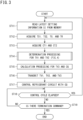
- FIG. 3 is a flowchart illustrating an example of information processing of the main controller 55.
- the main controller 55 reads the latest setting information SI from the memory after startup (step ST11).
- the main controller 55 acquires TS1, TS2, TO, and TR, which are detection results related to temperature (step ST12), and acquires CT1 and CT2, which are the detection result of CO2 concentration in the target space RM (step ST13).
- the main controller 55 executes determination processing for the TV1 and TV2, which are the target values of supply airflow (step ST14). Details of this determination processing ( FIG. 4 ) will be described later.
- the main controller 55 executes calculation processing for TV3, which is the target value of exhaust airflow, and CQ, which is a controlled variable for the refrigerant circuit 60 (step ST15).
- This calculation processing calculates the TV3 and the CQ on the basis of the TV1 and TV2 determined in the current control cycle.
- the main controller 55 calculates a temperature adjustment load for bringing the supply air SA to the set temperature SIt from the TV1 to TV3 determined in the current control cycle and the current TS1, TS2, TO, and TR, and determines CQ, which is a controlled variable for the refrigerant circuit 60, on the basis of the calculated temperature adjustment load.
- the main controller 55 transmits the determined TV1 to TV3 to the controllers 25A, 25B, and 44, respectively (step ST16).
- the main controller 55 transmits the TV1 to the first controller 25A, transmits the TV2 to the second controller 25B, and transmits the TV3 to the third controller 44.
- the main controller 55 controls the refrigerant circuit 60 with the CQ determined in the step ST15 (step ST17), and determines whether or not a predetermined control cycle (for example, 30 seconds) has elapsed (step ST18).
- a predetermined control cycle for example, 30 seconds
- the main controller 55 returns the process to before the step ST11.
- the main controller 55 determines the presence or absence of a termination command from the input device 70 (step ST19).
- step ST19 If the determination result in the step ST19 is negative, the main controller 55 returns the process to before the ST18. If the determination result in step ST19 is positive, the main controller 55 terminates the process.
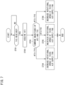
- FIG. 4 is a flowchart illustrating an example of determination processing (step ST14 in FIG. 3 ) for the target value of supply airflow.
- the memory of the main controller 55 holds a reference table that defines the correspondence relationship between the type of supply airflow and the target values TV1 and TV2 of supply airflow.
- TH is a CO2 concentration threshold set in advance to determine whether or not strong ventilation is required, and is set to, for example, 1000 ppm.
- step ST32 determines whether CT2 ⁇ TH (step ST33).
- step ST34 determines whether CT2 ⁇ TH (step ST34).
- the main controller 55 reads the target value of supply airflow corresponding to "strong wind" from the reference table and sets the read target values as TV1 and TV2.
- the main controller 55 reads the target values of supply airflow corresponding to "strong wind” and “breeze” from the reference table, and sets the target value corresponding to "strong wind” as TV1 and the target value corresponding to "breeze” as TV2.
- the main controller 55 reads the target values of supply airflow corresponding to "strong wind” and “breeze” from the reference table, and sets the target value corresponding to "strong wind” as TV2 and the target value corresponding to "breeze” as TV1.
- the main controller 55 reads the target value of supply airflow corresponding to "breeze” from the reference table and sets the read target values as TV1 and TV2.
- FIG. 5 is a flowchart illustrating an example of information processing of the first controller 25A.
- the first controller 25A determines whether or not TV1 has been received from the main controller 55 (step ST51), and if so, acquires AF1 from the detection result of the first air supply detector 23A (step ST52).
- the first controller 25A compares the magnitudes of the AF1 and the TV1 (step ST53), and executes the following processing according to the comparison result.
- the first controller 25A autonomously adjusts the rotational speed of its own first air supply fan 22A on the basis of the TV1 received from the main controller 55 and the AF1 that can be detected by its own detector 23A.
- the first air supply unit 20A including the first air supply fan 22A, the first air supply detector 23A, and the first controller 25A, corresponds to a unit capable of autonomously adjusting the first supply airflow AF1.
- FIG. 6 is a flowchart illustrating an example of information processing of the second controller 25B.
- the second controller 25B determines whether or not TV2 has been received from the main controller 55 (step ST71), and if so, acquires AF2 from the detection result of the second air supply detector 23B (step ST72).
- the second controller 25B compares the magnitudes of the AF2 and the TV2 (step ST73), and executes the following processing according to the comparison result.
- the second controller 25B autonomously adjusts the rotational speed of its own second air supply fan 22B on the basis of the TV2 received from the main controller 55 and the AF2 that can be detected by its own detector 23B.
- the second air supply unit 20B including the second air supply fan 22B, the second air supply detector 23B, and the second controller 25B, corresponds to a unit capable of autonomously adjusting the second supply airflow AF2.
- FIG. 7 is a flowchart illustrating an example of information processing of the third controller 44.
- the third controller 44 determines whether or not TV3 has been received from the main controller 55 (step ST91), and if so, acquires AF3 from the detection result of the exhaust detector 43 (step ST92).
- the third controller 44 compares the magnitudes of the AF3 and TV3 (step ST93), and executes the following processing according to the comparison result.
- the third controller 44 autonomously adjusts the rotational speed of its own exhaust fan 42 on the basis of the TV3 received from the main controller 55 and the AF3 that can be detected by its own detector 43.
- the exhaust unit 40 including the exhaust fan 42, the exhaust detector 43, and the third controller 44, corresponds to a unit capable of autonomously adjusting the exhaust airflow AF3.
- FIG. 8 is a longitudinal sectional view of a building illustrating another example of the overall configuration of the ventilation system 1.
- Difference 1 There are a plurality of target spaces RM1 and RM2 indoors, defined by an interior wall 3.
- the air supply units 20A and 20B are installed in the target spaces RM1 and RM2, respectively.
- the CO2 sensors 80A and 80B are installed in the target spaces RM1 and RM2, respectively.
- Input devices 70A and 70B are installed in the target spaces RM1 and RM2, respectively, and settings can be input by the user to each of the input devices 70A and 70B.
- the embodiment in FIG. 8 has the advantage that the ventilation rate and the supply air temperature can be set for each of the target spaces RM1 and RM2, and the ventilation for suppressing the CO2 concentration can be individually executed in each of the target spaces RM1 and RM2.
- the CO2 sensor is exemplified as an example of the indoor monitoring sensor 80, but the monitoring sensor 80 may be, for example, the following sensors.
- the monitoring sensor 80 that can be employed in the ventilation system 1 according to the present embodiment is not limited to the CO2 sensor, and may be any sensor that detects state information (such as CO2 concentration, particle concentration, odor level, presence or absence of people, and number of people), which is at least one of an indoor air state, the presence or absence of people indoors, and the number of people indoors.
- state information such as CO2 concentration, particle concentration, odor level, presence or absence of people, and number of people
- the air supply unit 20 and exhaust unit 30 without controllers may be adopted, and overall control to adjust the fan speed may also be performed by the main controller 55.
- the main controller 55 and the first to third controllers 25A, 25B, and 44 perform control in a distributed manner, so that the processing load on the main controller 55 can be reduced, and less expensive control modules can be used.
- controllers 25A and 25B relay the detection results of some measurement devices (for example, the CO2 sensor 80), the increase in signal lines can be suppressed as much as possible.
- control unit CU (specifically, the first and second controllers 25A and 25B) executes the following first air supply control and second air supply control, it is possible to adjust each of the first supply airflow AF 1 and the second supply airflow AF2.
- the supply air SA subjected to a heat exchange can be supplied to the plurality of areas in an airflow adjustable manner.
- control unit CU determines the target value TV1 of the first supply airflow and the target value TV2 of the second supply airflow on the basis of the detection results of the monitoring sensors 80A and 80B.
- ventilation contributing to the improvement of the indoor environment for example, ventilation that decreases the CO2 concentration
- ventilation that decreases the CO2 concentration can be performed for each area.
- the control unit CU (specifically, third controller 44) executes the following exhaust control, the exhaust airflow AF3 can be adjusted. Therefore, for example, appropriate ventilation can be performed by balancing the sum of the first supply airflow AF1 and the second supply airflow AF2 with the exhaust airflow AF3.
- Exhaust control Control to adjust the rotational speed of the exhaust fan 42 so that the exhaust airflow AF3 becomes a target value TV3
- control unit CU determines the target value TV3 of the exhaust airflow and a controlled variable CQ for the refrigerant circuit 60 on the basis of the target value TV1 of the first supply airflow and the target value TV2 of the second supply airflow.
- the refrigerant circuit 60 can be controlled with an appropriate heat recovery amount while balancing the sum of the first supply airflow AF1 and the second supply airflow AF2 with the exhaust airflow AF3.
- the first to third controllers 25A, 25B, and 44 adjust the fan speeds based on the target values TV1 to TV3, and the main controller 55 determines the target values TV1 to TV3 and the controlled variable CQ for the refrigerant circuit 60.
- the processing load on the main controller 55 can be suppressed as compared with the case where the main controller 55 is responsible for all processing. Therefore, for example, the manufacturing cost of the ventilation system 1 can be reduced by, for example, using a controller for an air conditioner as the main controller 55.
- the ventilation system 1 includes: the first air supply unit 20A that includes the first air supply fan 22A, the first air supply detector 23A, and the first controller 25A and is capable of autonomously adjusting the first supply airflow AF 1; and the second air supply unit 20B that includes the second air supply fan 22B, the second air supply detector 23B, and the second controller 25B and is capable of autonomously adjusting the second supply airflow AF2.
- the first air supply unit 20A and the second air supply unit 20B can be placed in the same room RM or in different rooms RM1 and RM2, for example depending on user needs.
- the flexibility of the installation places of the air supply units 20A and 20B is improved.
- the ventilation system 1 includes the exhaust unit 40 that includes the exhaust fan 42, the exhaust detector 43, and the third controller 44 and is capable of autonomously adjusting the exhaust airflow AF3.
- the exhaust unit 40 can be placed indoors or outdoors, for example depending on user needs.
- the flexibility of the installation place of the exhaust unit 40 is improved.
Landscapes
- Engineering & Computer Science (AREA)
- Chemical & Material Sciences (AREA)
- Combustion & Propulsion (AREA)
- Mechanical Engineering (AREA)
- General Engineering & Computer Science (AREA)
- Physics & Mathematics (AREA)
- Fluid Mechanics (AREA)
- Air Conditioning Control Device (AREA)
- Ventilation (AREA)
Abstract
Description
- The present disclosure relates to a ventilation system.
-
Patent Literature 1 discloses a ventilation system (heat recovery outdoor air conditioning system) capable of first type ventilation. This ventilation system includes a heat exchanger, a supply air path and exhaust air path that allow the inside and outside of a target space to communicate with each other via the heat exchanger, an air supply fan that supplies air outside the target space to the target space via the supply air path, and an exhaust fan that exhausts air in the target space to the outside of the target space via the exhaust air path. - In the above ventilation system, the heat exchanger of a heat pump outdoor air conditioner recovers heat from the return air in the indoor zone and then exhausts the heat to the outdoors, and uses the recovered heat for heat exchange with outside air from outdoors to supply the air to the indoor zone.
- PATENT LITERATURE 1:
Japanese Laid-Open Patent Publication No. 03-20573 - Since the conventional ventilation system is configured by the air supply fan, the exhaust fan, and the heat exchanger being housed in a single casing, it is not assumed, for example, to supply the supply air subjected to a heat exchange to a plurality of areas or to adjust the amount of supply air for each of the plurality of areas.
- An object of the present disclosure is to provide a ventilation system capable of supplying supply air subjected to a heat exchange to a plurality of areas in an airflow adjustable manner.
-
- (1) A ventilation system according to the present disclosure includes: a refrigerant circuit that circulates refrigerant through a compressor, a first heat exchanger, and a second heat exchanger; a first air supply fan and a second air supply fan that supply outdoor air to an indoor space; an exhaust fan that exhausts indoor air to an outdoor space; an air supply path that connects the outdoor space to the indoor space and has an interior in which the first heat exchanger and the first air supply fan and second air supply fan located further toward an indoor side than the first heat exchanger are arranged; an exhaust air path that connects the outdoor space to the indoor space and has an interior in which the second heat exchanger and the exhaust fan are arranged; a first air supply detector for detecting a first supply airflow blown out by the first air supply fan; a second air supply detector for detecting a second supply airflow blown out by the second air supply fan; and a control unit. The control unit executes first air supply control to adjust a rotational speed of the first air supply fan so that the first supply airflow becomes a target value, and second air supply control to adjust a rotational speed of the second air supply fan so that the second supply airflow becomes a target value.
- In the ventilation system according to the present disclosure, the first heat exchanger and the first air supply fan and second air supply fan located further toward an indoor side than the first heat exchanger are included in the interior of the air supply path, so that the supply air subjected to a heat exchange can be supplied to the plurality of areas.
- In addition, since the control unit executes the first air supply control and the second air supply control, it is possible to adjust each of the first supply airflow and the second supply airflow. Thus, the supply air subjected to a heat exchange can be supplied to the plurality of areas in an airflow adjustable manner.
- (2) In a case where the ventilation system according to the present disclosure further includes a monitoring sensor for detecting state information that is at least one of an indoor air state, presence or absence of people indoors, and number of people indoors, the control unit may determine the target value of the first supply airflow and the target value of the second supply airflow on the basis of a detection result of the monitoring sensor.
- In this case, since the control unit determines the target value of the first supply airflow and the target value of the second supply airflow on the basis of the detection result of the monitoring sensor, ventilation contributing to the improvement of the indoor environment (for example, ventilation that decreases the CO2 concentration) can be performed for each area.
- (3) In a case where the ventilation system according to the present disclosure further includes an exhaust detector for detecting an exhaust airflow blown out by the exhaust fan, the control unit may execute exhaust control to adjust a rotational speed of the exhaust fan so that the exhaust airflow becomes a target value.
- In this case, since the control unit executes the exhaust control, the exhaust airflow can be adjusted. Thus, for example, appropriate ventilation can be performed by balancing the sum of the first supply airflow and the second supply airflow with the exhaust airflow.
- (4) In the ventilation system according to the present disclosure, the control unit may determine the target value of the exhaust airflow and a controlled variable for the refrigerant circuit on the basis of the target value of the first supply airflow and the target value of the second supply airflow.
- In this case, since the control unit determines the target value of the exhaust airflow and a controlled variable for the refrigerant circuit on the basis of the target value of the first supply airflow and the target value of the second supply airflow, for example, the refrigerant circuit can be controlled with an appropriate heat recovery amount while balancing the sum of the first supply airflow and the second supply airflow with the exhaust airflow.
- (5) In the ventilation system according to the present disclosure, the control unit may include: a main controller that determines the target value of the first supply airflow, the target value of the second supply airflow, the target value of the exhaust airflow, and the controlled variable for the refrigerant circuit; a first controller that executes the first air supply control; a second controller that executes the second air supply control; and a third controller that executes the exhaust control.
- In this case, the first to third controllers adjust the fan speed based on the target value, and the main controller determines the target value of each airflow and the controlled variable for the refrigerant circuit, so that the processing load on the main controller can be suppressed as compared with the case where the main controller is responsible for all processing. Therefore, for example, the manufacturing cost of the ventilation system can be reduced by, for example, using a controller for an air conditioner as the main controller.
- (6) The ventilation system according to the present disclosure may further include: a first air supply unit that includes the first air supply fan, the first air supply detector, and the first controller and is capable of autonomously adjusting the first supply airflow; and a second air supply unit that includes the second air supply fan, the second air supply detector, and the second controller and is capable of autonomously adjusting the second supply airflow.
- In this case, the first air supply unit and the second air supply unit can be placed in the same room or in different rooms, for example depending on user needs. Thus, the flexibility of the installation places of the air supply units is improved.
- (7) The ventilation system according to the present disclosure may further include an exhaust unit that includes the exhaust fan, the exhaust detector, and the third controller and is capable of autonomously adjusting the exhaust airflow.
- In this case, the exhaust unit can be placed indoors or outdoors, for example depending on user needs. Thus, the flexibility of the installation place of the exhaust unit is improved.
-
-
FIG. 1 is a longitudinal sectional view of a building illustrating an example of the overall configuration of a ventilation system. -
FIG. 2 is a block diagram illustrating an example of the control system of a control unit. -
FIG. 3 is a flowchart illustrating an example of information processing of a main controller. -
FIG. 4 is a flowchart illustrating an example of determination processing for the target value of supply airflow. -
FIG. 5 is a flowchart illustrating an example of information processing of a first controller. -
FIG. 6 is a flowchart illustrating an example of information processing of a second controller. -
FIG. 7 is a flowchart illustrating an example of information processing of a third controller. -
FIG. 8 is a longitudinal sectional view of a building illustrating another example of the overall configuration of the ventilation system. -
FIG. 1 is a longitudinal sectional view of a building illustrating an example of the overall configuration of aventilation system 1. - In
FIG. 1 , reference signs "OA", "SA", "RA", and "EA" have the following meanings. - OA: Outdoor air (outside air). This is also the air that the
system 1 draws in from outdoors. - SA: Air (supply air) that the
system 1 sends indoors. - RA: Indoor air (return air). This is also the air that the
system 1 draws in from indoors. - EA: Air (exhaust air) that the
system 1 discharges outdoors. - The
ventilation system 1 according to the present embodiment provides first-type ventilation for an indoor target space RM while performing temperature adjustment for the supply air SA and heat recovery from the return air RA. The target space RM is, for example, the indoor space of various buildings such as an office building, a hospital, and a factory. - The target space RM is preferably an airtight room for a predetermined use, but may be, for example, an indoor corridor, a staircase, an entrance, or the like. Furthermore, in the target space RM, an
indoor unit 2 of an air conditioning system separate from theventilation system 1 may be installed. - As illustrated in
FIG. 1 , theventilation system 1 includes aheat exchange unit 10 on the utilization side (air supply side), anair supply unit 20, aheat exchange unit 30 on the recovery side (exhaust side), anexhaust unit 40, acompressor unit 50, and arefrigerant circuit 60. - The
heat exchange unit 10 and theair supply unit 20 are installed in the ceiling space of the target space RM, and theheat exchange unit 30, theexhaust unit 40, and thecompressor unit 50 are installed inside the wall of the target space RM. - The
ventilation system 1 further includes aninput device 70 that is an input equipment allowing users to input operations, and amonitoring sensor 80. Theinput device 70 is, for example, a remote controller attached to the wall surface of the target space RM. Theinput device 70 may be installed in a room different from the target space RM, such as a management room (not illustrated). - The
monitoring sensor 80 monitors an indoor air state, and is capable of wired or wireless communication conforming to a predetermined communication standard. In the present embodiment, themonitoring sensor 80 is assumed to be a CO2 sensor that is attached to the ceiling surface of the target space RM and that detects CO2 concentration. - The installation position of each unit illustrated in
FIG. 1 is an example, and for example, theheat exchange unit 30 and theexhaust unit 40 may be arranged in the ceiling space, and the return air RA may be drawn in from the ceiling side. - Alternatively, at least one of the
heat exchange unit 30, theexhaust unit 40, and thecompressor unit 50 may be installed outdoors. - The
ventilation system 1 includes a plurality of (two in the illustrated example)air supply units 20 of the same product. Hereinafter, one of the plurality ofair supply units 20 is referred to as a firstair supply unit 20A, and the other is referred to as a secondair supply unit 20B. - The
ventilation system 1 includes a plurality of (two in the illustrated example)CO2 sensors 80 of the same product. Hereinafter, one of the plurality ofCO2 sensors 80 is referred to as afirst CO2 sensor 80A, and the other is referred to as asecond CO2 sensor 80B. - In the present embodiment, the
first CO2 sensor 80A satisfies the followinginstallation condition 1, and thesecond CO2 sensor 80B satisfies the followinginstallation condition 2. - Installation Condition 1: The distance (for example, within 1 m) from the
first CO2 sensor 80A to the firstair supply unit 20A is shorter than the distance from thefirst CO2 sensor 80A to the secondair supply unit 20B. - Installation Condition 2: The distance (for example, within 1 m) from the
second CO2 sensor 80B to the secondair supply unit 20B is shorter than the distance from thesecond CO2 sensor 80B to the firstair supply unit 20A. - The
heat exchange unit 10 on the utilization side has acasing 11 and a plurality of devices housed in thecasing 11. The plurality of devices includes a utilization-side heat exchanger (hereinafter referred to as "first heat exchanger") 12, which is an element device of therefrigerant circuit 60, and an outsideair temperature sensor 13. - The
first heat exchanger 12 is, for example, a cross-fin tube or microchannel heat exchanger, and exchanges heat between the refrigerant flowing inside thefirst heat exchanger 12 and the outside air OA. - The first
air supply unit 20A has acasing 21A and a plurality of devices housed in thecasing 21A. The plurality of devices includes a firstair supply fan 22A, a firstair supply detector 23A, a first supplyair temperature sensor 24A, and afirst controller 25A. - The first
air supply fan 22A is, for example, a centrifugal fan with controllable fan speed. The firstair supply detector 23A is, for example, an airflow sensor for detecting airflow, or a sensor for detecting air velocity, differential pressure, fan speed, or the like (hereinafter referred to as "airflow equivalent"), which are physical quantities from which the airflow is calculated. Therefore, if thefirst controller 25A has the function of counting the fan speed, thefirst controller 25A also serves as the firstair supply detector 23A. - The
first controller 25A is, for example, a control module including a circuit board and an integrated circuit such as a central processing unit (CPU) and memory mounted on the circuit board. The integrated circuit may include at least a field-programmable gate array (FPGA) or an application-specific IC (ASIC). - The
first controller 25A is capable of communication control with other controllers and sensors conforming to a predetermined communication standard, and is capable of performing predetermined information processing such as control for adjusting the fan speed so that the airflow of the firstair supply fan 22A becomes a target value. - The second
air supply unit 20B has acasing 21B and a plurality of devices housed in thecasing 21B. The plurality of devices includes a secondair supply fan 22B, a secondair supply detector 23B, a second supplyair temperature sensor 24B, and asecond controller 25B. - The second
air supply fan 22B is, for example, a centrifugal fan with controllable fan speed. The secondair supply detector 23B is, for example, an airflow sensor for detecting airflow or a sensor for detecting the airflow equivalent. Therefore, if thesecond controller 25B has the function of counting the fan speed, thesecond controller 25B also serves as the secondair supply detector 23B. - The
second controller 25B is, for example, a control module including a circuit board and an integrated circuit such as a CPU and memory mounted on the circuit board. The integrated circuit may include at least the FPGA or the ASIC. - The
second controller 25B is capable of communication control with other controllers and sensors conforming to a predetermined communication standard, and is capable of performing predetermined information processing such as control for adjusting the fan speed so that the airflow of the secondair supply fan 22B becomes a target value. - The
heat exchange unit 30 on the recovery side has acasing 31 and a plurality of devices housed in thecasing 31. The plurality of devices includes a recovery-side heat exchanger (hereinafter referred to as "second heat exchanger") 32, which is an element device of therefrigerant circuit 60, and a returnair temperature sensor 33. - The
second heat exchanger 32 is, for example, a cross-fin tube or microchannel heat exchanger, and exchanges heat between the refrigerant flowing inside thesecond heat exchanger 32 and the return air RA. - The
exhaust unit 40 has acasing 41 and a plurality of devices housed in thecasing 41. The plurality of devices includes anexhaust fan 42, anexhaust detector 43, and athird controller 44. - The
exhaust fan 42 is, for example, a centrifugal fan with controllable fan speed. Theexhaust detector 43 is, for example, an airflow sensor for detecting airflow or a sensor for detecting the airflow equivalent. Therefore, if thethird controller 44 has the function of counting the fan speed, thethird controller 44 also serves as theair supply detector 43. - The
third controller 44 is, for example, a control module including a circuit board and an integrated circuit such as a CPU and memory mounted on the circuit board. The integrated circuit may include at least the FPGA or the ASIC. - The
third controller 44 is capable of communication control with other controllers and sensors conforming to a predetermined communication standard, and is capable of performing predetermined information processing such as control for adjusting the fan speed so that the airflow of theexhaust fan 42 becomes a target value. - The
compressor unit 50 includes acasing 51 and a plurality of devices housed in thecasing 51. The plurality of devices includes acompressor 52, a four-way valve 53, anexpansion valve 54, and amain controller 55. - The
refrigerant circuit 60 circulates refrigerant through thecompressor 52, thefirst heat exchanger 12, and thesecond heat exchanger 32, and has thecompressor 52, the four-way valve 53, theexpansion valve 54, thefirst heat exchanger 12, thesecond heat exchanger 32, and arefrigerant pipe 61 that connects these components. - The
main controller 55 is, for example, a control module including a circuit board and an integrated circuit such as a CPU and memory mounted on the circuit board. The integrated circuit may include at least the FPGA or the ASIC. - The
main controller 55 is capable of performing communication control with other controllers and sensors conforming to a predetermined communication standard and of performing predetermined information processing such as determination of a controlled variable for therefrigerant circuit 60 according to the ventilation rate. - In the ceiling space of the target space RM, the suction port of the
casing 11 communicates with an air supply port outdoors through a duct d1. - In the ceiling space of the target space RM, the suction ports of the
casings casing 11 by a duct d2 being a branch pipe. The blow-out ports of thecasings - Therefore, the air path formed by the duct d1, the
casing 11, the duct d2, and thecasings first heat exchanger 12 and the first and secondair supply fans first heat exchanger 12 are arranged. - Note that a blow-out unit (not illustrated) having a filter, a wind direction plate, and the like may be coupled to the blow-out side of the
casings - Under the floor of the target space RM, the suction port of the
casing 31 is airtightly connected to the air supply port in the floor surface by a duct d3 including a branch pipe. - Inside the wall of the target space RM, the suction port of the
casing 41 is airtightly connected to the blow-out port of thecasing 31 by a duct d4. The blow-out port of thecasing 41 communicates with an exhaust port outdoors through a duct d5. - Therefore, the air path formed by the duct d3, the
casing 31, the duct d4, thecasing 41, and the duct d5 connects the outdoors to the indoors, and constitutes an "exhaust air path" in which thesecond heat exchanger 32 and theexhaust fan 42 are disposed. - When the first
air supply fan 22A and the secondair supply fan 22B are driven, the duct d1, thecasing 11, and the duct d2 in the air supply path become negative pressure, and the outside air OA is drawn into the duct d1. - At this time, the outside
air temperature sensor 13 detects the temperature of the outside air OA before heat exchange with thefirst heat exchanger 12. The air subjected to heat exchange in thefirst heat exchanger 12 passes through the duct d2 and thecasings air temperature sensors - When the
exhaust fan 42 is driven, the duct d4, thecasing 31, and the duct d3 in the exhaust air path become negative pressure, and the return air RA is drawn into the duct d3. - At this time, the return
air temperature sensor 33 detects the temperature of the return air RA before heat exchange with thesecond heat exchanger 32. The air after the heat exchange with thesecond heat exchanger 32 passes through thecasing 41 and the duct d5 and is delivered outdoors as the exhaust air EA. - In the
ventilation system 1 inFIG. 1 , the exhaust air path may be configured such that theheat exchange unit 30 is located on the blow-out side (downstream side in the exhaust direction) of theexhaust unit 40. - In the
ventilation system 1 inFIG. 1 , theheat exchange unit 30 and theexhaust unit 40 may be an integrated unit housed in the same casing. - Element Device of Refrigerant Circuit and Temperature Adjustment Operation
- The
compressor 52 is an element device of therefrigerant circuit 60, sucking in low-pressure gaseous refrigerant and discharging high-pressure gaseous refrigerant. - The
compressor 52 is, for example, a variable displacement type (variable capacity type), the displacement of which is variable by the inverter control of an electric motor. However, thecompressor 52 may be of a constant-displacement type or two ormore compressors 52 may be connected in parallel. - The
expansion valve 54 is, for example, an electric valve for adjusting the flow rate and pressure of the refrigerant in thepipe 61. The refrigerant pressure to thefirst heat exchanger 12 is adjusted by controlling the opening degree of theexpansion valve 54. - The four-
way valve 53 reverses the flow direction of the refrigerant in the circuit, and switches the refrigerant discharged fromcompressor 52 to eitherfirst heat exchanger 12 orsecond heat exchanger 32. Therefore, the temperature adjustment operation that can be executed by theventilation system 1 includes "cold air supply" in which the outside air OA is cooled and supplied indoors, and "warm air supply" in which the outside air OA is heated and supplied indoors. - Specifically, in the case of cold air supply in which cold air obtained by cooling the outside air OA is used as the supply air SA, the four-
way valve 53 is maintained in the state indicated by the solid line inFIG. 1 . - In this case, the
first heat exchanger 12 on the utilization side functions as an evaporator and cools the outside air OA, and thesecond heat exchanger 32 on the recovery side functions as a condenser and heats the return air RA. The heating of the return air RA corresponds to heat recovery from the return air RA. - Meanwhile, in the case of the warm air supply in which warm air obtained by heating the outside air OA is used as the supply air SA, the four-
way valve 53 is maintained in the state indicated by the broken line inFIG. 1 . - In this case, the
first heat exchanger 12 on the utilization side functions as a condenser and heats the outside air OA, and thesecond heat exchanger 32 on the recovery side functions as an evaporator and cools the return air RA. The cooling of the return air RA corresponds to heat recovery from the return air RA. - In the
ventilation system 1 according to the present embodiment, the four-way valve 53 of therefrigerant circuit 60 may be omitted. In this case, thefirst heat exchanger 12 is used only as either an evaporator or a condenser, resulting in theventilation system 1 that performs only the cold air supply or the warm air supply. -
FIG. 2 is a block diagram illustrating an example of the control system of theventilation system 1. - The meanings of the parameters included in
FIG. 2 are as follows. - SI: Setting information that can be input to the
input device 70. For example, the following SIc and SIt are included: - SIc: Supply airflow rate identification information defined in stages (such as "breeze", "weak wind", "medium wind", and "strong wind", or identification numbers from "
level 1" to "level 4") - SIt: Set temperature of the supply air SA
- TS1: Detection result of the first supply
air temperature sensor 24A (supply air temperature of the first air supply fan) - TS2: Detection result of the second supply
air temperature sensor 24B (supply air temperature of the second air supply fan) - TO: Detection result of the outside air temperature sensor 13 (outside air temperature)
- TR: Detection result of the return air temperature sensor 33 (return air temperature)
- AF1: Airflow (first supply airflow) blown out by the first
air supply fan 22A - However, if the first
air supply detector 23A is an airflow sensor, AF1 is the detection result of the sensor, and if the firstair supply detector 23A is a sensor that detects an airflow equivalent, AF1 is the airflow calculated from the detection result of the sensor. AF1 may be the airflow calculated from the fan speed counted by thefirst controller 25A. - AF2: Airflow (second supply airflow) blown out by the second
air supply fan 22B - However, if the second
air supply detector 23B is an airflow sensor, AF2 is the detection result of the sensor, and if the secondair supply detector 23B is a sensor that detects an airflow equivalent, AF2 is the airflow calculated from the detection result of the sensor. AF2 may be the airflow calculated from the fan speed counted by thesecond controller 25B. - AF3: Airflow (exhaust airflow) blown out by the
exhaust fan 42 - However, if the
exhaust detector 43 is an airflow sensor, AF3 is the detection result of the sensor, and if theexhaust detector 43 is a sensor that detects an airflow equivalent, AF3 is the airflow calculated from the detection result of the sensor. AF3 may be the airflow calculated from the fan speed counted by thethird controller 44. - CT1: Detection result of the
first CO2 sensor 80A (CO2 concentration near the first air supply fan) - CT2: Detection result of the
second CO2 sensor 80B (CO2 concentration near the second air supply fan) - TV1: Target value of airflow (first supply airflow) blown out by the first
air supply fan 22A - TV2: Target value of airflow (second supply airflow) blown out by the second
air supply fan 22B - TV3: Target value of airflow (exhaust airflow) blown out by the
exhaust fan 42 - CQ: Controlled variable (compressor discharge amount, refrigerant flow rate or direction, and the like) for the
refrigerant circuit 60 - As illustrated in
FIG. 2 , the control system of theventilation system 1 includes a control unit CU composed of a group of controllers that perform wired or wireless communication. The control unit CU includes, for example, themain controller 55, thefirst controller 25A, thesecond controller 25B, and thethird controller 44. - The
main controller 55 is connected to theinput device 70. When the user inputs SI to theinput device 70, theinput device 70 transmits the SI to themain controller 55. Themain controller 55 records the received SI in its own memory. - The
main controller 55 is connected to each of the temperature-relatedsensors main controller 55 receives TS1, TS2, TO, and TR from thesensors - If the first supply
air temperature sensor 24A is connected to thefirst controller 25A, the TS1 may be transmitted to themain controller 55 with thefirst controller 25A as a relay node. - If the second supply
air temperature sensor 24B is connected to thesecond controller 25B, the TS2 may be transmitted to themain controller 55 with thesecond controller 25B as a relay node. - The
main controller 55 is connected to thefirst controller 25A, thesecond controller 25B, and thethird controller 44. - Upon determining TV1, the
main controller 55 transmits the determined TV1 to thefirst controller 25A, upon determining the TV2, themain controller 55 transmits the determined TV2 to thesecond controller 25B, and upon determining TV3, themain controller 55 transmits the determined TV3 to thethird controller 44. - The
main controller 55 is connected to thecompressor 52, the four-way valve 53, and theexpansion valve 54. Upon determining CQ, themain controller 55 outputs the determined CQ to at least one of thecompressor 52, the four-way valve 53, and theexpansion valve 54. - The
first controller 25A is connected to the firstair supply fan 22A, the firstair supply detector 23A, and thefirst CO2 sensor 80A. - The
first controller 25A transfers the CT1 received from thefirst CO2 sensor 80A to themain controller 55. If thefirst CO2 sensor 80A is connected to themain controller 55, the CT1 is directly transmitted to themain controller 55. - If the first
air supply detector 23A is an airflow sensor, thefirst controller 25A sets the detection result received from thedetector 23A as AF1. - If the first
air supply detector 23A is an airflow equivalent sensor, thefirst controller 25A calculates AF1 from the detection result received from thedetector 23A. Thefirst controller 25A may set the airflow calculated from the fan speed counted by itself as AF1. - Upon receiving the TV1, the
first controller 25A calculates the fan speed on the basis of the TV1 and the AF1, and outputs the calculated speed to the firstair supply fan 22A. - The
second controller 25B is connected to the secondair supply fan 22B, the secondair supply detector 23B, and thesecond CO2 sensor 80B. - The
second controller 25B transfers the CT2 received from thesecond CO2 sensor 80B to themain controller 55. If thesecond CO2 sensor 80B is connected to themain controller 55, the CT2 is directly transmitted to themain controller 55. - If the second
air supply detector 23B is an airflow sensor, thesecond controller 25B sets the detection result received from thedetector 23B as AF2. - If the second
air supply detector 23B is an airflow equivalent sensor, thesecond controller 25B calculates AF2 from the detection result received from thedetector 23B. Thesecond controller 25B may set the airflow calculated from the fan speed counted by itself as AF2. - Upon receiving the TV2, the
second controller 25B calculates the fan speed on the basis of the TV2 and the AF2, and outputs the calculated speed to the secondair supply fan 22B. - The
third controller 44 is connected to theexhaust fan 42 and theexhaust detector 43. - If the
exhaust detector 43 is an airflow sensor, thethird controller 44 sets the detection result received from thedetector 43 as AF3. - If the
exhaust detector 43 is an airflow equivalent sensor, thethird controller 44 calculates AF3 from the detection result received from thedetector 43. Thethird controller 44 may set the airflow calculated from the fan speed counted by itself as AF3. - Upon receiving the TV3, the
third controller 44 calculates the fan speed on the basis of the TV3 and the AF3, and outputs the calculated speed to theexhaust fan 42. -
FIG. 3 is a flowchart illustrating an example of information processing of themain controller 55. - As illustrated in
FIG. 3 , themain controller 55 reads the latest setting information SI from the memory after startup (step ST11). - Next, the
main controller 55 acquires TS1, TS2, TO, and TR, which are detection results related to temperature (step ST12), and acquires CT1 and CT2, which are the detection result of CO2 concentration in the target space RM (step ST13). - Then the
main controller 55 executes determination processing for the TV1 and TV2, which are the target values of supply airflow (step ST14). Details of this determination processing (FIG. 4 ) will be described later. - Next, the
main controller 55 executes calculation processing for TV3, which is the target value of exhaust airflow, and CQ, which is a controlled variable for the refrigerant circuit 60 (step ST15). This calculation processing calculates the TV3 and the CQ on the basis of the TV1 and TV2 determined in the current control cycle. - For example, the
main controller 55 determines the TV3 using the formula of TV3 = TV1 + TV2 to balance the air supply and exhaust amount for the target space RM. - In addition, the
main controller 55 calculates a temperature adjustment load for bringing the supply air SA to the set temperature SIt from the TV1 to TV3 determined in the current control cycle and the current TS1, TS2, TO, and TR, and determines CQ, which is a controlled variable for therefrigerant circuit 60, on the basis of the calculated temperature adjustment load. - Next, the
main controller 55 transmits the determined TV1 to TV3 to thecontrollers - Specifically, the
main controller 55 transmits the TV1 to thefirst controller 25A, transmits the TV2 to thesecond controller 25B, and transmits the TV3 to thethird controller 44. - Next, the
main controller 55 controls therefrigerant circuit 60 with the CQ determined in the step ST15 (step ST17), and determines whether or not a predetermined control cycle (for example, 30 seconds) has elapsed (step ST18). - If the determination result in the step ST18 is positive, the
main controller 55 returns the process to before the step ST11. - If the determination result in the step ST18 is negative, the
main controller 55 determines the presence or absence of a termination command from the input device 70 (step ST19). - If the determination result in the step ST19 is negative, the
main controller 55 returns the process to before the ST18. If the determination result in step ST19 is positive, themain controller 55 terminates the process. -
FIG. 4 is a flowchart illustrating an example of determination processing (step ST14 inFIG. 3 ) for the target value of supply airflow. - Here, it is assumed that there are four types of supply airflow that can be designated using SIc, that is, breeze, weak wind, medium wind, and strong wind, and the type designated by the user using SIc is "breeze". Furthermore, the memory of the
main controller 55 holds a reference table that defines the correspondence relationship between the type of supply airflow and the target values TV1 and TV2 of supply airflow. - As illustrated in
FIG. 4 , themain controller 55 extracts the type (= breeze) included in the acquired SIc (step ST31). - Next, the
main controller 55 determines whether CT1 ≥ TH (step ST32). "TH" is a CO2 concentration threshold set in advance to determine whether or not strong ventilation is required, and is set to, for example, 1000 ppm. - If the determination result in step ST32 is positive, the
main controller 55 determines whether CT2 ≥ TH (step ST33). - Even if the determination result in step ST32 is negative, the
main controller 55 determines whether CT2 ≥ TH (step ST34). - If the determination result in step ST33 is positive, the
main controller 55 sets TV1 and TV2 to the target values equivalent to strong wind regardless of the type (= breeze) extracted from SIc (step ST35). - Specifically, the
main controller 55 reads the target value of supply airflow corresponding to "strong wind" from the reference table and sets the read target values as TV1 and TV2. - If the determination result in step ST33 is negative, the
main controller 55 sets only TV1 to the target value equivalent to strong wind (step ST36), and follows the extracted type (= breeze) for TV2. - Specifically, the
main controller 55 reads the target values of supply airflow corresponding to "strong wind" and "breeze" from the reference table, and sets the target value corresponding to "strong wind" as TV1 and the target value corresponding to "breeze" as TV2. - If the determination result in step ST34 is positive, the
main controller 55 sets only TV2 to the target value corresponding to strong wind (step ST37), and follows the extracted type (= breeze) for TV1. - Specifically, the
main controller 55 reads the target values of supply airflow corresponding to "strong wind" and "breeze" from the reference table, and sets the target value corresponding to "strong wind" as TV2 and the target value corresponding to "breeze" as TV1. - If the determination result in step ST34 is negative, the target values of TV1 and TV2 are set according to the extracted type (= breeze) of SIc (step ST35).
- Specifically, the
main controller 55 reads the target value of supply airflow corresponding to "breeze" from the reference table and sets the read target values as TV1 and TV2. -
FIG. 5 is a flowchart illustrating an example of information processing of thefirst controller 25A. - As illustrated in
FIG. 5 , after startup, thefirst controller 25A determines whether or not TV1 has been received from the main controller 55 (step ST51), and if so, acquires AF1 from the detection result of the firstair supply detector 23A (step ST52). - Next, the
first controller 25A compares the magnitudes of the AF1 and the TV1 (step ST53), and executes the following processing according to the comparison result. - That is, if AF1 < TV1, the
first controller 25A increases the rotational speed of the firstair supply fan 22A by a predetermined amount (step ST54). If AF1 = TV1, the rotational speed is maintained (step ST55), and if AF1 > TV1, the rotational speed is decreased by a predetermined amount (step ST56). - In this manner, the
first controller 25A autonomously adjusts the rotational speed of its own firstair supply fan 22A on the basis of the TV1 received from themain controller 55 and the AF1 that can be detected by itsown detector 23A. - Therefore, the first
air supply unit 20A, including the firstair supply fan 22A, the firstair supply detector 23A, and thefirst controller 25A, corresponds to a unit capable of autonomously adjusting the first supply airflow AF1. -
FIG. 6 is a flowchart illustrating an example of information processing of thesecond controller 25B. - As illustrated in
FIG. 6 , after startup, thesecond controller 25B determines whether or not TV2 has been received from the main controller 55 (step ST71), and if so, acquires AF2 from the detection result of the secondair supply detector 23B (step ST72). - Next, the
second controller 25B compares the magnitudes of the AF2 and the TV2 (step ST73), and executes the following processing according to the comparison result. - That is, if AF2 < TV2, the
second controller 25B increases the rotational speed of the secondair supply fan 22B by a predetermined amount (step ST74). If AF2 = TV2, the rotational speed is maintained (step ST75), and if AF2 > TV2, the rotational speed is decreased by a predetermined amount (step ST76). - In this manner, the
second controller 25B autonomously adjusts the rotational speed of its own secondair supply fan 22B on the basis of the TV2 received from themain controller 55 and the AF2 that can be detected by itsown detector 23B. - Therefore, the second
air supply unit 20B, including the secondair supply fan 22B, the secondair supply detector 23B, and thesecond controller 25B, corresponds to a unit capable of autonomously adjusting the second supply airflow AF2. -
FIG. 7 is a flowchart illustrating an example of information processing of thethird controller 44. - As illustrated in
FIG. 7 , after startup, thethird controller 44 determines whether or not TV3 has been received from the main controller 55 (step ST91), and if so, acquires AF3 from the detection result of the exhaust detector 43 (step ST92). - Next, the
third controller 44 compares the magnitudes of the AF3 and TV3 (step ST93), and executes the following processing according to the comparison result. - That is, if AF3 < TV3, the
third controller 44 increases the rotational speed of theexhaust fan 42 by a predetermined amount (step ST94). If AF3 = TV3, the rotational speed is maintained (step ST95), and if AF3 > TV3, the rotational speed is decreased by a predetermined amount (step ST96). - In this manner, the
third controller 44 autonomously adjusts the rotational speed of itsown exhaust fan 42 on the basis of the TV3 received from themain controller 55 and the AF3 that can be detected by itsown detector 43. - Therefore, the
exhaust unit 40, including theexhaust fan 42, theexhaust detector 43, and thethird controller 44, corresponds to a unit capable of autonomously adjusting the exhaust airflow AF3. -
FIG. 8 is a longitudinal sectional view of a building illustrating another example of the overall configuration of theventilation system 1. - The differences between the embodiment in
FIG. 8 and the embodiment inFIG. 1 are as follows. - Difference 1: There are a plurality of target spaces RM1 and RM2 indoors, defined by an interior wall 3.
- Difference 2: The
air supply units - Difference 3: The
CO2 sensors - Difference 3:
Input devices input devices - Therefore, the embodiment in
FIG. 8 has the advantage that the ventilation rate and the supply air temperature can be set for each of the target spaces RM1 and RM2, and the ventilation for suppressing the CO2 concentration can be individually executed in each of the target spaces RM1 and RM2. - In the above-described embodiment, the CO2 sensor is exemplified as an example of the
indoor monitoring sensor 80, but themonitoring sensor 80 may be, for example, the following sensors. - 1) Suspended particle sensor: A sensor that detects the concentration of suspended particles such as smoke and dust
- 2) Odor sensor: A sensor that detects the degree of indoor odor
- 3) Presence sensor: A sensor that detects the presence or absence of people in a room
- 4) Number-of-people count sensor: A sensor that detects the number of people in a room
- In the case of adopting the suspended particle sensor, it is only required to perform intervention control to increase the ventilation rate when the particle concentration becomes a predetermined value or more, and in the case of adopting the odor sensor, it is only required to perform intervention control to increase the ventilation rate when the degree of odor becomes a predetermined value or more.
- Similarly, in the case of adopting the presence sensor, it is only required to perform intervention control to increase the ventilation rate in response to the detection of the presence of people, and in the case of adopting the number-of-people count sensor is adopted, it is only required to perform intervention control to increase the ventilation rate when the number of people becomes a predetermined value or more.
- As described above, the
monitoring sensor 80 that can be employed in theventilation system 1 according to the present embodiment is not limited to the CO2 sensor, and may be any sensor that detects state information (such as CO2 concentration, particle concentration, odor level, presence or absence of people, and number of people), which is at least one of an indoor air state, the presence or absence of people indoors, and the number of people indoors. - In the above-described embodiment, the
air supply unit 20 andexhaust unit 30 without controllers may be adopted, and overall control to adjust the fan speed may also be performed by themain controller 55. - However, by adopting the
air supply unit 20 andexhaust unit 30 with the controllers mounted as in the above-described embodiment, themain controller 55 and the first tothird controllers main controller 55 can be reduced, and less expensive control modules can be used. - In addition, in the above-described embodiment, since the
controllers -
- (1) In the
ventilation system 1 according to the present embodiment, thefirst heat exchanger 12 and the firstair supply fan 22A and secondair supply fan 22B located further toward an indoor side than thefirst heat exchanger 12 are included in the interior of the air supply path, so that the supply air SA subjected to a heat exchange can be supplied to a plurality of areas. - In addition, since the control unit CU (specifically, the first and
second controllers supply airflow AF 1 and the second supply airflow AF2. Thus, the supply air SA subjected to a heat exchange can be supplied to the plurality of areas in an airflow adjustable manner. -
- First air supply control: Control to adjust the rotational speed of the first
air supply fan 22A so that the first supply airflow AF1 becomes a target value TV1 - Second air supply control: Control to adjust the rotational speed of the second
air supply fan 22B so that the second supply airflow AF2 becomes a target value TV2 - (2) In the
ventilation system 1 according to the present embodiment, the control unit CU (specifically, the main controller 55) determines the target value TV1 of the first supply airflow and the target value TV2 of the second supply airflow on the basis of the detection results of themonitoring sensors - Therefore, ventilation contributing to the improvement of the indoor environment (for example, ventilation that decreases the CO2 concentration) can be performed for each area.
- (3) In the
ventilation system 1 according to the present embodiment, since the control unit CU (specifically, third controller 44) executes the following exhaust control, the exhaust airflow AF3 can be adjusted. Therefore, for example, appropriate ventilation can be performed by balancing the sum of the first supply airflow AF1 and the second supply airflow AF2 with the exhaust airflow AF3. - Exhaust control: Control to adjust the rotational speed of the
exhaust fan 42 so that the exhaust airflow AF3 becomes a target value TV3 - (4) In the
ventilation system 1 according to the present embodiment, the control unit CU (specifically, the main controller 55) determines the target value TV3 of the exhaust airflow and a controlled variable CQ for therefrigerant circuit 60 on the basis of the target value TV1 of the first supply airflow and the target value TV2 of the second supply airflow. - Thus, for example, the
refrigerant circuit 60 can be controlled with an appropriate heat recovery amount while balancing the sum of the first supply airflow AF1 and the second supply airflow AF2 with the exhaust airflow AF3. - (5) In the
ventilation system 1 according to the present embodiment, the first tothird controllers main controller 55 determines the target values TV1 to TV3 and the controlled variable CQ for therefrigerant circuit 60. - Thus, the processing load on the
main controller 55 can be suppressed as compared with the case where themain controller 55 is responsible for all processing. Therefore, for example, the manufacturing cost of theventilation system 1 can be reduced by, for example, using a controller for an air conditioner as themain controller 55. - (6) The
ventilation system 1 according to the present embodiment includes: the firstair supply unit 20A that includes the firstair supply fan 22A, the firstair supply detector 23A, and thefirst controller 25A and is capable of autonomously adjusting the firstsupply airflow AF 1; and the secondair supply unit 20B that includes the secondair supply fan 22B, the secondair supply detector 23B, and thesecond controller 25B and is capable of autonomously adjusting the second supply airflow AF2. - Therefore, the first
air supply unit 20A and the secondair supply unit 20B can be placed in the same room RM or in different rooms RM1 and RM2, for example depending on user needs. Thus, the flexibility of the installation places of theair supply units - (7) The
ventilation system 1 according to the present embodiment includes theexhaust unit 40 that includes theexhaust fan 42, theexhaust detector 43, and thethird controller 44 and is capable of autonomously adjusting the exhaust airflow AF3. Thus, theexhaust unit 40 can be placed indoors or outdoors, for example depending on user needs. Thus, the flexibility of the installation place of theexhaust unit 40 is improved. - The present disclosure is not limited to the above exemplification, but is defined by claims, and is intended to include all modifications within the meaning and scope equivalent to the claims.
-
- 1
- ventilation system
- 12
- first heat exchanger
- 20A
- first air supply unit
- 20B
- second air supply unit
- 22A
- first air supply fan
- 22B
- second air supply fan
- 23A
- first air supply detector
- 23B
- second air supply detector
- 24A
- first supply air temperature sensor
- 24B
- second supply air temperature sensor
- 25A
- first controller
- 25B
- second controller
- 30
- heat exchange unit
- 31
- casing
- 32
- second heat exchanger
- 33
- return air temperature sensor
- 40
- exhaust unit
- 42
- exhaust fan
- 43
- exhaust detector
- 44
- third controller
- 52
- compressor
- 53
- four-way valve
- 54
- expansion valve
- 55
- main controller
- 60
- refrigerant circuit
- 61
- refrigerant pipe
- 70
- input device (remote controller)
- 80
- monitoring sensor (CO2 sensor)
- 80A
- monitoring sensor (CO2 sensor)
- 80B
- monitoring sensor (CO2 sensor)
- CU
- control unit
- AF1
- first supply airflow
- AF2
- second supply airflow
- AF3
- exhaust airflow
- TV1
- target value of first supply airflow
- TV2
- target value of second supply airflow
- TV3
- target value of exhaust airflow
- CQ
- controlled variable for refrigerant circuit
Claims (7)
- A ventilation system (1) comprising:a refrigerant circuit (60) that circulates refrigerant through a compressor (52), a first heat exchanger (12), and a second heat exchanger (32);a first air supply fan (22A) and a second air supply fan (22B) that supply outdoor air to an indoor space;an exhaust fan (42) that exhausts indoor air to an outdoor space;an air supply path that connects the outdoor space to the indoor space and has an interior in which the first heat exchanger (12) and the first air supply fan (22A) and second air supply fan (22B) located further toward an indoor side than the first heat exchanger (12) are arranged;an exhaust air path that connects the outdoor space to the indoor space and has an interior in which the second heat exchanger (32) and the exhaust fan (42) are arranged;a first air supply detector (23A) for detecting a first supply airflow (AF1) blown out by the first air supply fan (22A);a second air supply detector (23B) for detecting a second supply airflow (AF2) blown out by the second air supply fan (22B); anda control unit (CU),wherein the control unit (CU) executesfirst air supply control to adjust a rotational speed of the first air supply fan (22A) so that the first supply airflow (AF1) becomes a target value (TV1), andsecond air supply control to adjust a rotational speed of the second air supply fan (22B) so that the second supply airflow (AF2) becomes a target value (TV2).
- The ventilation system (1) according to claim 1, further comprising a monitoring sensor (80A, 80B) for detecting state information that is at least one of an indoor air state, presence or absence of people indoors, and number of people indoors,
wherein the control unit (CU) determines the target value (TV1) of the first supply airflow and the target value (TV2) of the second supply airflow on a basis of a detection result of the monitoring sensor (80A, 80B). - The ventilation system (1) according to claim 1 or 2, further comprising an exhaust detector (43) for detecting an exhaust airflow (AF3) blown out by the exhaust fan (42),
wherein the control unit (CU) executes exhaust control to adjust a rotational speed of the exhaust fan (42) so that the exhaust airflow (AF3) becomes a target value (TV3). - The ventilation system (1) according to claim 3, wherein the control unit (CU) determines the target value (TV3) of the exhaust airflow and a controlled variable (CQ) for the refrigerant circuit (60) on a basis of the target value (TV1) of the first supply airflow and the target value (TV2) of the second supply airflow.
- The ventilation system (1) according to claim 4, wherein the control unit (CU) includes:a main controller (55) that determines the target value (TV1) of the first supply airflow, the target value (TV2) of the second supply airflow, the target value (TV3) of the exhaust airflow, and the controlled variable (CQ) for the refrigerant circuit (60);a first controller (25A) that executes the first air supply control;a second controller (25B) that executes the second air supply control; anda third controller (44) that executes the exhaust control.
- The ventilation system (1) according to claim 5, further comprising:a first air supply unit (20A) that includes the first air supply fan (22A), the first air supply detector (23A), and the first controller (25A) and is capable of autonomously adjusting the first supply airflow (AF1); anda second air supply unit (25B) that includes the second air supply fan (22B), the second air supply detector (23B), and the second controller (25B) and is capable of autonomously adjusting the second supply airflow (AF2).
- The ventilation system (1) according to claim 5 or 6, further comprising an exhaust unit (40) that includes the exhaust fan (42), the exhaust detector (43), and the third controller (44) and is capable of autonomously adjusting the exhaust airflow (AF3).
Applications Claiming Priority (2)
| Application Number | Priority Date | Filing Date | Title |
|---|---|---|---|
| JP2021204824A JP7280529B1 (en) | 2021-12-17 | 2021-12-17 | ventilation system |
| PCT/JP2022/039233 WO2023112481A1 (en) | 2021-12-17 | 2022-10-21 | Ventilation system |
Publications (3)
| Publication Number | Publication Date |
|---|---|
| EP4450889A1 true EP4450889A1 (en) | 2024-10-23 |
| EP4450889A4 EP4450889A4 (en) | 2025-03-12 |
| EP4450889B1 EP4450889B1 (en) | 2026-05-06 |
Family
ID=86395925
Family Applications (1)
| Application Number | Title | Priority Date | Filing Date |
|---|---|---|---|
| EP22907015.6A Active EP4450889B1 (en) | 2021-12-17 | 2022-10-21 | Ventilation system |
Country Status (6)
| Country | Link |
|---|---|
| US (1) | US20240310071A1 (en) |
| EP (1) | EP4450889B1 (en) |
| JP (2) | JP7280529B1 (en) |
| CN (1) | CN118765361A (en) |
| AU (1) | AU2022414435C1 (en) |
| WO (1) | WO2023112481A1 (en) |
Families Citing this family (1)
| Publication number | Priority date | Publication date | Assignee | Title |
|---|---|---|---|---|
| CN120845855A (en) * | 2025-07-11 | 2025-10-28 | 北京航天河科技发展有限公司 | A method and device for controlling ventilation of underground space |
Family Cites Families (35)
| Publication number | Priority date | Publication date | Assignee | Title |
|---|---|---|---|---|
| FR2435670A1 (en) * | 1974-12-30 | 1980-04-04 | Barthalon Maurice | Space heating system with heat pump device - has parameters of system chosen to allow compressor to operate at resonant frequency |
| JPS52115548A (en) * | 1976-03-24 | 1977-09-28 | Matsushita Electric Ind Co Ltd | Heat pump type air conditioning system |
| JPS5980627U (en) * | 1982-11-25 | 1984-05-31 | 株式会社東芝 | air conditioner |
| JPS6136641A (en) * | 1984-07-26 | 1986-02-21 | Matsushita Electric Ind Co Ltd | Air conditioning and air ventilation device |
| JPS6172945A (en) * | 1984-09-18 | 1986-04-15 | Kajima Corp | Air conditioner |
| JPS61197932A (en) * | 1985-02-26 | 1986-09-02 | Mitsubishi Electric Corp | Ventilation device |
| JPH0635891B2 (en) * | 1985-07-19 | 1994-05-11 | 松下精工株式会社 | Air conditioner |
| JPH01217144A (en) * | 1988-02-24 | 1989-08-30 | Matsushita Seiko Co Ltd | Ventilation type air conditioner |
| JPH0320573A (en) | 1989-06-19 | 1991-01-29 | Sanyo Electric Co Ltd | Air-conditioning apparatus |
| JPH0835684A (en) * | 1994-07-26 | 1996-02-06 | Natl House Ind Co Ltd | Air conditioner for building |
| JP2000220877A (en) * | 1999-01-29 | 2000-08-08 | Daikin Ind Ltd | Ventilation air conditioner |
| JP2002162067A (en) * | 2000-11-21 | 2002-06-07 | Daikin Ind Ltd | Air conditioner |
| CN1228577C (en) * | 2002-09-27 | 2005-11-23 | 木村工机株式会社 | Floor type heat pump air conditioner |
| JP2006317078A (en) * | 2005-05-12 | 2006-11-24 | Toyo Eng Works Ltd | Heat pump air conditioner |
| JP4979308B2 (en) * | 2006-08-28 | 2012-07-18 | 三機工業株式会社 | Air conditioning system |
| KR20080065178A (en) * | 2007-01-08 | 2008-07-11 | 주식회사 대우일렉트로닉스 | Multi air conditioner using one indoor unit |
| JP5098346B2 (en) * | 2007-01-30 | 2012-12-12 | パナソニック株式会社 | Ventilation air conditioner |
| JP5076745B2 (en) * | 2007-08-31 | 2012-11-21 | パナソニック株式会社 | Ventilation air conditioner |
| JP5451995B2 (en) * | 2007-12-18 | 2014-03-26 | 株式会社ササクラ | Air conditioning equipment |
| JP5426322B2 (en) * | 2009-10-30 | 2014-02-26 | 三機工業株式会社 | Air conditioning system and air conditioning method |
| JP5862266B2 (en) * | 2011-12-13 | 2016-02-16 | ダイキン工業株式会社 | Ventilation system |
| JP5533973B2 (en) * | 2012-10-10 | 2014-06-25 | ダイキン工業株式会社 | Humidity control ventilator |
| CN104329759B (en) * | 2014-11-10 | 2017-05-10 | 上海理工大学 | Temperature control dehumidification system and temperature control dehumidification method for fresh air of radiation air conditioner |
| CN204665595U (en) * | 2015-05-29 | 2015-09-23 | 北京网电盈科科技发展有限公司 | Tandem heat-recycling air treatment device |
| CN109695913A (en) * | 2017-10-24 | 2019-04-30 | 宁波方太厨具有限公司 | A kind of kitchen air conditioner system and Water heater for kitchen system matched with the air-conditioning system |
| WO2019082377A1 (en) * | 2017-10-27 | 2019-05-02 | 三菱電機株式会社 | Heat pump system |
| US20190154270A1 (en) * | 2017-11-22 | 2019-05-23 | Evolving Living Innovation Center E.L.I.C. S.r.l. | Heat pump apparatus for air renewal in domestic rooms and the method of operation thereof |
| JPWO2019146121A1 (en) * | 2018-01-29 | 2020-06-18 | 三菱電機株式会社 | Air conditioning system |
| JP2019168194A (en) * | 2018-03-26 | 2019-10-03 | 三菱電機株式会社 | Outside air treatment unit |
| JP6761890B1 (en) * | 2019-04-15 | 2020-09-30 | ダイキン工業株式会社 | Air conditioning system |
| JP2020183838A (en) * | 2019-05-08 | 2020-11-12 | ダイキン工業株式会社 | Air conditioning system |
| JP7245730B2 (en) * | 2019-06-24 | 2023-03-24 | ダイキン工業株式会社 | air conditioning system |
| KR102363938B1 (en) * | 2019-10-18 | 2022-02-15 | 김주형 | Method and apparatus for adjust the air supply according to the exhaust of indoor |
| JP6958657B2 (en) * | 2020-03-31 | 2021-11-02 | ダイキン工業株式会社 | Air conditioning system |
| CN113669876A (en) * | 2020-04-30 | 2021-11-19 | 广东松下环境系统有限公司 | Ventilation system and ventilation method |
-
2021
- 2021-12-17 JP JP2021204824A patent/JP7280529B1/en active Active
-
2022
- 2022-10-21 EP EP22907015.6A patent/EP4450889B1/en active Active
- 2022-10-21 CN CN202280083147.4A patent/CN118765361A/en active Pending
- 2022-10-21 AU AU2022414435A patent/AU2022414435C1/en active Active
- 2022-10-21 WO PCT/JP2022/039233 patent/WO2023112481A1/en not_active Ceased
-
2023
- 2023-05-10 JP JP2023077873A patent/JP7541259B2/en active Active
-
2024
- 2024-05-23 US US18/672,844 patent/US20240310071A1/en active Pending
Also Published As
| Publication number | Publication date |
|---|---|
| US20240310071A1 (en) | 2024-09-19 |
| JP7541259B2 (en) | 2024-08-28 |
| JP2023100914A (en) | 2023-07-19 |
| EP4450889B1 (en) | 2026-05-06 |
| AU2022414435B2 (en) | 2024-07-18 |
| CN118765361A (en) | 2024-10-11 |
| AU2022414435A1 (en) | 2024-07-04 |
| AU2022414435C1 (en) | 2024-08-08 |
| WO2023112481A1 (en) | 2023-06-22 |
| JP7280529B1 (en) | 2023-05-24 |
| JP2023090074A (en) | 2023-06-29 |
| EP4450889A4 (en) | 2025-03-12 |
Similar Documents
| Publication | Publication Date | Title |
|---|---|---|
| US4987952A (en) | Apparatus for use in dehumidifying and otherwise conditioning air within a room | |
| US12228308B2 (en) | Fan unit, fan unit system, and air treatment system | |
| US10151505B2 (en) | Air-conditioning apparatus | |
| KR20100119646A (en) | Air conditioner | |
| US12140328B2 (en) | Zone monitoring systems and methods for a zoning system | |
| US20200309394A1 (en) | Hvac unit utilizing selectively modulated flow rates with hot gas reheat circuit | |
| JP6856154B2 (en) | Air conditioning system | |
| EP3792565A1 (en) | Air conditioning system | |
| JP6661775B2 (en) | Air conditioner | |
| EP4450889B1 (en) | Ventilation system | |
| JP2011149615A (en) | Air conditioning system | |
| KR20120019279A (en) | Demand control system and method for chiller | |
| EP4450882B1 (en) | VENTILATION SYSTEM | |
| US20240003580A1 (en) | Air-conditioning system, controller for air-conditioning apparatus, and control method for air-conditioning apparatus | |
| JP7856884B2 (en) | Ventilation system | |
| KR20000047501A (en) | Control method for electro-drive expansion valve | |
| JPH1089752A (en) | Whole building air conditioning system | |
| JPH10267358A (en) | Collective duct type air conditioning system | |
| JP3015551B2 (en) | Air conditioner | |
| KR100988617B1 (en) | Air Conditioner and Control Method | |
| KR20110046044A (en) | Facility control system | |
| JPH03186137A (en) | Duct type air conditioner | |
| JP2023050660A (en) | ventilation system | |
| KR20050105738A (en) | (a) multi type air conditioner and method of controlling the same | |
| JP2003207197A (en) | Control method of air conditioner and air conditioner |
Legal Events
| Date | Code | Title | Description |
|---|---|---|---|
| STAA | Information on the status of an ep patent application or granted ep patent |
Free format text: STATUS: THE INTERNATIONAL PUBLICATION HAS BEEN MADE |
|
| PUAI | Public reference made under article 153(3) epc to a published international application that has entered the european phase |
Free format text: ORIGINAL CODE: 0009012 |
|
| STAA | Information on the status of an ep patent application or granted ep patent |
Free format text: STATUS: REQUEST FOR EXAMINATION WAS MADE |
|
| 17P | Request for examination filed |
Effective date: 20240610 |
|
| AK | Designated contracting states |
Kind code of ref document: A1 Designated state(s): AL AT BE BG CH CY CZ DE DK EE ES FI FR GB GR HR HU IE IS IT LI LT LU LV MC ME MK MT NL NO PL PT RO RS SE SI SK SM TR |
|
| P01 | Opt-out of the competence of the unified patent court (upc) registered |
Free format text: CASE NUMBER: APP_1115/2025 Effective date: 20250108 |
|
| A4 | Supplementary search report drawn up and despatched |
Effective date: 20250210 |
|
| RIC1 | Information provided on ipc code assigned before grant |
Ipc: F24F 7/08 20060101ALI20250204BHEP Ipc: F24F 7/007 20060101ALI20250204BHEP Ipc: F24F 120/10 20180101ALI20250204BHEP Ipc: F24F 110/70 20180101ALI20250204BHEP Ipc: F24F 11/74 20180101AFI20250204BHEP |
|
| DAV | Request for validation of the european patent (deleted) | ||
| DAX | Request for extension of the european patent (deleted) | ||
| STAA | Information on the status of an ep patent application or granted ep patent |
Free format text: STATUS: EXAMINATION IS IN PROGRESS |
|
| 17Q | First examination report despatched |
Effective date: 20250717 |
|
| GRAP | Despatch of communication of intention to grant a patent |
Free format text: ORIGINAL CODE: EPIDOSNIGR1 |
|
| STAA | Information on the status of an ep patent application or granted ep patent |
Free format text: STATUS: GRANT OF PATENT IS INTENDED |
|
| INTG | Intention to grant announced |
Effective date: 20260123 |
|
| GRAS | Grant fee paid |
Free format text: ORIGINAL CODE: EPIDOSNIGR3 |
|
| GRAA | (expected) grant |
Free format text: ORIGINAL CODE: 0009210 |
|
| STAA | Information on the status of an ep patent application or granted ep patent |
Free format text: STATUS: THE PATENT HAS BEEN GRANTED |
|
| AK | Designated contracting states |
Kind code of ref document: B1 Designated state(s): AL AT BE BG CH CY CZ DE DK EE ES FI FR GB GR HR HU IE IS IT LI LT LU LV MC ME MK MT NL NO PL PT RO RS SE SI SK SM TR |
|
| REG | Reference to a national code |
Ref country code: CH Ref legal event code: F10 Free format text: ST27 STATUS EVENT CODE: U-0-0-F10-F00 (AS PROVIDED BY THE NATIONAL OFFICE) Effective date: 20260506 Ref country code: GB Ref legal event code: FG4D |