EP4450882A1 - Ventilation system - Google Patents
Ventilation system Download PDFInfo
- Publication number
- EP4450882A1 EP4450882A1 EP22907005.7A EP22907005A EP4450882A1 EP 4450882 A1 EP4450882 A1 EP 4450882A1 EP 22907005 A EP22907005 A EP 22907005A EP 4450882 A1 EP4450882 A1 EP 4450882A1
- Authority
- EP
- European Patent Office
- Prior art keywords
- mode
- air
- control
- blow
- ventilation
- Prior art date
- Legal status (The legal status is an assumption and is not a legal conclusion. Google has not performed a legal analysis and makes no representation as to the accuracy of the status listed.)
- Granted
Links
Images




Classifications
-
- F—MECHANICAL ENGINEERING; LIGHTING; HEATING; WEAPONS; BLASTING
- F24—HEATING; RANGES; VENTILATING
- F24F—AIR-CONDITIONING; AIR-HUMIDIFICATION; VENTILATION; USE OF AIR CURRENTS FOR SCREENING
- F24F11/00—Control or safety arrangements
- F24F11/62—Control or safety arrangements characterised by the type of control or by internal processing, e.g. using fuzzy logic, adaptive control or estimation of values
- F24F11/63—Electronic processing
- F24F11/65—Electronic processing for selecting an operating mode
-
- F—MECHANICAL ENGINEERING; LIGHTING; HEATING; WEAPONS; BLASTING
- F24—HEATING; RANGES; VENTILATING
- F24F—AIR-CONDITIONING; AIR-HUMIDIFICATION; VENTILATION; USE OF AIR CURRENTS FOR SCREENING
- F24F11/00—Control or safety arrangements
- F24F11/30—Control or safety arrangements for purposes related to the operation of the system, e.g. for safety or monitoring
-
- F—MECHANICAL ENGINEERING; LIGHTING; HEATING; WEAPONS; BLASTING
- F24—HEATING; RANGES; VENTILATING
- F24F—AIR-CONDITIONING; AIR-HUMIDIFICATION; VENTILATION; USE OF AIR CURRENTS FOR SCREENING
- F24F11/00—Control or safety arrangements
- F24F11/30—Control or safety arrangements for purposes related to the operation of the system, e.g. for safety or monitoring
- F24F11/46—Improving electric energy efficiency or saving
-
- F—MECHANICAL ENGINEERING; LIGHTING; HEATING; WEAPONS; BLASTING
- F24—HEATING; RANGES; VENTILATING
- F24F—AIR-CONDITIONING; AIR-HUMIDIFICATION; VENTILATION; USE OF AIR CURRENTS FOR SCREENING
- F24F11/00—Control or safety arrangements
- F24F11/50—Control or safety arrangements characterised by user interfaces or communication
-
- F—MECHANICAL ENGINEERING; LIGHTING; HEATING; WEAPONS; BLASTING
- F24—HEATING; RANGES; VENTILATING
- F24F—AIR-CONDITIONING; AIR-HUMIDIFICATION; VENTILATION; USE OF AIR CURRENTS FOR SCREENING
- F24F11/00—Control or safety arrangements
- F24F11/70—Control systems characterised by their outputs; Constructional details thereof
- F24F11/72—Control systems characterised by their outputs; Constructional details thereof for controlling the supply of treated air, e.g. its pressure
- F24F11/74—Control systems characterised by their outputs; Constructional details thereof for controlling the supply of treated air, e.g. its pressure for controlling air flow rate or air velocity
-
- F—MECHANICAL ENGINEERING; LIGHTING; HEATING; WEAPONS; BLASTING
- F24—HEATING; RANGES; VENTILATING
- F24F—AIR-CONDITIONING; AIR-HUMIDIFICATION; VENTILATION; USE OF AIR CURRENTS FOR SCREENING
- F24F11/00—Control or safety arrangements
- F24F11/70—Control systems characterised by their outputs; Constructional details thereof
- F24F11/72—Control systems characterised by their outputs; Constructional details thereof for controlling the supply of treated air, e.g. its pressure
- F24F11/74—Control systems characterised by their outputs; Constructional details thereof for controlling the supply of treated air, e.g. its pressure for controlling air flow rate or air velocity
- F24F11/77—Control systems characterised by their outputs; Constructional details thereof for controlling the supply of treated air, e.g. its pressure for controlling air flow rate or air velocity by controlling the speed of ventilators
-
- F—MECHANICAL ENGINEERING; LIGHTING; HEATING; WEAPONS; BLASTING
- F24—HEATING; RANGES; VENTILATING
- F24F—AIR-CONDITIONING; AIR-HUMIDIFICATION; VENTILATION; USE OF AIR CURRENTS FOR SCREENING
- F24F12/00—Use of energy recovery systems in air conditioning, ventilation or screening
- F24F12/001—Use of energy recovery systems in air conditioning, ventilation or screening with heat-exchange between supplied and exhausted air
-
- F—MECHANICAL ENGINEERING; LIGHTING; HEATING; WEAPONS; BLASTING
- F24—HEATING; RANGES; VENTILATING
- F24F—AIR-CONDITIONING; AIR-HUMIDIFICATION; VENTILATION; USE OF AIR CURRENTS FOR SCREENING
- F24F12/00—Use of energy recovery systems in air conditioning, ventilation or screening
- F24F12/001—Use of energy recovery systems in air conditioning, ventilation or screening with heat-exchange between supplied and exhausted air
- F24F12/006—Use of energy recovery systems in air conditioning, ventilation or screening with heat-exchange between supplied and exhausted air using an air-to-air heat exchanger
-
- F—MECHANICAL ENGINEERING; LIGHTING; HEATING; WEAPONS; BLASTING
- F24—HEATING; RANGES; VENTILATING
- F24F—AIR-CONDITIONING; AIR-HUMIDIFICATION; VENTILATION; USE OF AIR CURRENTS FOR SCREENING
- F24F7/00—Ventilation
- F24F7/007—Ventilation with forced flow
-
- F—MECHANICAL ENGINEERING; LIGHTING; HEATING; WEAPONS; BLASTING
- F24—HEATING; RANGES; VENTILATING
- F24F—AIR-CONDITIONING; AIR-HUMIDIFICATION; VENTILATION; USE OF AIR CURRENTS FOR SCREENING
- F24F7/00—Ventilation
- F24F7/04—Ventilation with ducting systems, e.g. by double walls; with natural circulation
- F24F7/06—Ventilation with ducting systems, e.g. by double walls; with natural circulation with forced air circulation, e.g. by fan positioning of a ventilator in or against a conduit
- F24F7/08—Ventilation with ducting systems, e.g. by double walls; with natural circulation with forced air circulation, e.g. by fan positioning of a ventilator in or against a conduit with separate ducts for supplied and exhausted air with provisions for reversal of the input and output systems
-
- F—MECHANICAL ENGINEERING; LIGHTING; HEATING; WEAPONS; BLASTING
- F24—HEATING; RANGES; VENTILATING
- F24F—AIR-CONDITIONING; AIR-HUMIDIFICATION; VENTILATION; USE OF AIR CURRENTS FOR SCREENING
- F24F2110/00—Control inputs relating to air properties
- F24F2110/10—Temperature
-
- F—MECHANICAL ENGINEERING; LIGHTING; HEATING; WEAPONS; BLASTING
- F24—HEATING; RANGES; VENTILATING
- F24F—AIR-CONDITIONING; AIR-HUMIDIFICATION; VENTILATION; USE OF AIR CURRENTS FOR SCREENING
- F24F2110/00—Control inputs relating to air properties
- F24F2110/10—Temperature
- F24F2110/12—Temperature of the outside air
-
- F—MECHANICAL ENGINEERING; LIGHTING; HEATING; WEAPONS; BLASTING
- F24—HEATING; RANGES; VENTILATING
- F24F—AIR-CONDITIONING; AIR-HUMIDIFICATION; VENTILATION; USE OF AIR CURRENTS FOR SCREENING
- F24F2110/00—Control inputs relating to air properties
- F24F2110/50—Air quality properties
- F24F2110/65—Concentration of specific substances or contaminants
- F24F2110/70—Carbon dioxide
-
- F—MECHANICAL ENGINEERING; LIGHTING; HEATING; WEAPONS; BLASTING
- F24—HEATING; RANGES; VENTILATING
- F24F—AIR-CONDITIONING; AIR-HUMIDIFICATION; VENTILATION; USE OF AIR CURRENTS FOR SCREENING
- F24F2120/00—Control inputs relating to users or occupants
- F24F2120/10—Occupancy
-
- Y—GENERAL TAGGING OF NEW TECHNOLOGICAL DEVELOPMENTS; GENERAL TAGGING OF CROSS-SECTIONAL TECHNOLOGIES SPANNING OVER SEVERAL SECTIONS OF THE IPC; TECHNICAL SUBJECTS COVERED BY FORMER USPC CROSS-REFERENCE ART COLLECTIONS [XRACs] AND DIGESTS
- Y02—TECHNOLOGIES OR APPLICATIONS FOR MITIGATION OR ADAPTATION AGAINST CLIMATE CHANGE
- Y02B—CLIMATE CHANGE MITIGATION TECHNOLOGIES RELATED TO BUILDINGS, e.g. HOUSING, HOUSE APPLIANCES OR RELATED END-USER APPLICATIONS
- Y02B30/00—Energy efficient heating, ventilation or air conditioning [HVAC]
- Y02B30/56—Heat recovery units
-
- Y—GENERAL TAGGING OF NEW TECHNOLOGICAL DEVELOPMENTS; GENERAL TAGGING OF CROSS-SECTIONAL TECHNOLOGIES SPANNING OVER SEVERAL SECTIONS OF THE IPC; TECHNICAL SUBJECTS COVERED BY FORMER USPC CROSS-REFERENCE ART COLLECTIONS [XRACs] AND DIGESTS
- Y02—TECHNOLOGIES OR APPLICATIONS FOR MITIGATION OR ADAPTATION AGAINST CLIMATE CHANGE
- Y02B—CLIMATE CHANGE MITIGATION TECHNOLOGIES RELATED TO BUILDINGS, e.g. HOUSING, HOUSE APPLIANCES OR RELATED END-USER APPLICATIONS
- Y02B30/00—Energy efficient heating, ventilation or air conditioning [HVAC]
- Y02B30/70—Efficient control or regulation technologies, e.g. for control of refrigerant flow, motor or heating
Definitions
- the present disclosure relates to a ventilation system.
- Patent Literature 1 discloses a ventilation system capable of first type ventilation.
- This ventilation system includes a heat exchanger, a supply air path and exhaust air path that allow the inside and outside of a target space to communicate with each other via the heat exchanger, an air supply fan that supplies air outside the target space to the target space via the supply air path, and an exhaust fan that exhausts air in the target space to the outside of the target space via the exhaust air path.
- the heat exchanger of the heat pump heat exchanger recovers heat from the return air in the indoor zone and then exhausts the heat to the outdoors, and uses the recovered heat for heat exchange with outside air from outdoors to supply the air to the indoor zone.
- PATENT LITERATURE 1 Japanese Laid-Open Patent Publication No. 3-20573
- An object of the present disclosure is to diversify control modes related to ventilation function and temperature adjustment function in a ventilation system capable of recovering heat from return air.
- First mode A control mode having higher weighting on the state information, among the state information and the blow-out temperature that are usable for adjusting the indoor ventilation rate.
- Second mode A control mode having higher weighting on the blow-out temperature, among the state information and the blow-out temperature that are usable for adjusting the indoor ventilation rate.
- the ventilation system according to the present disclosure includes the above-described first mode and second mode as the types of the control modes performed by the control unit, it is possible to diversify the control modes related to ventilation function and temperature adjustment function in the ventilation system capable of recovering heat from return air.
- the ventilation system according to the present disclosure may further include an input equipment including type information of the control modes as setting information that can be input by a user.
- the ventilation system includes the input equipment including the control mode type information as the setting information that can be input by the user, thereby allowing the user to set the ventilation system to operate in either the first mode or the second mode.
- the input equipment may be capable of limiting the user who inputs the type information of the control modes.
- the user who inputs the type information of the control modes can be limited to, for example, a building manager, it is possible to prevent the occupants of a room, which is the target space of the ventilation system, from arbitrarily changing the control modes.
- control unit may execute the first mode regardless of the control mode type information input to the input equipment, if a detection result of the monitoring sensor exceeds a predetermined threshold value.
- control unit may be further capable of executing a third mode for determining whether to decrease, maintain, or increase the current ventilation rate on the basis of at least a detection result of the temperature sensor, a set value of the blow-out temperature, the detection result of the monitoring sensor, and a set value of the state information.
- control unit is capable of executing the third mode for determining whether to decrease, maintain, or increase the current ventilation rate on the basis of at least the above four parameters.
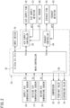
- FIG. 1 is a longitudinal sectional view of a building illustrating an example of the overall configuration of a ventilation system 1.
- the ventilation system 1 provides first-type ventilation for an indoor target space RM while performing temperature adjustment for the supply air SA and heat recovery from the return air RA.
- the target space RM is, for example, the indoor space of various buildings such as an office building, a hospital, and a factory.
- the target space RM is preferably an airtight room for a predetermined use, but may be, for example, an indoor corridor, a staircase, an entrance, or the like. Furthermore, in the target space RM, an indoor unit 2 of an air conditioning system separate from the ventilation system 1 may be installed.
- the ventilation system 1 includes a heat exchange unit 10 on the utilization side (air supply side), an air supply unit 20, a heat exchange unit 30 on the recovery side (exhaust side), an exhaust unit 40, a compressor unit 50, and a refrigerant circuit 60.
- the heat exchange unit 10 and the air supply unit 20 are installed in the ceiling space of the target space RM, and the heat exchange unit 30, the exhaust unit 40, and the compressor unit 50 are installed inside the wall of the target space RM.
- the ventilation system 1 further includes an input device 70 that is an input equipment allowing users to input operations, and a monitoring sensor 80.
- the input device 70 is, for example, a remote controller attached to the wall surface of the target space RM.
- the input device 70 may be installed in a room different from the target space RM, such as a management room (not illustrated).
- the monitoring sensor 80 monitors an indoor air state, and is capable of wired or wireless communication conforming to a predetermined communication standard.
- the monitoring sensor 80 is assumed to be a CO2 sensor that is attached to the ceiling surface of the target space RM and that detects CO2 concentration.
- each unit illustrated in FIG. 1 is an example, and for example, the heat exchange unit 30 and the exhaust unit 40 may be arranged in the ceiling space, and the return air RA may be drawn in from the ceiling side.
- At least one of the heat exchange unit 30, the exhaust unit 40, and the compressor unit 50 may be installed outdoors.
- the heat exchange unit 10 on the utilization side has a casing 11 and a plurality of devices housed in the casing 11.
- the plurality of devices includes a utilization-side heat exchanger (hereinafter referred to as "first heat exchanger") 12, which is an element device of the refrigerant circuit 60, and an outside air temperature sensor 13.
- the first heat exchanger 12 is, for example, a cross-fin tube or microchannel heat exchanger, and exchanges heat between the refrigerant flowing inside the first heat exchanger 12 and the outside air OA.
- the air supply unit 20 has a casing 21 and a plurality of devices housed in the casing 21.
- the plurality of devices includes an air supply fan 22, an air supply detector 23, a supply air temperature sensor 24, and an air supply controller 25.
- the air supply fan 22 is, for example, a centrifugal fan with controllable fan speed.
- the air supply detector 23 is, for example, an airflow sensor for detecting airflow, or a sensor for detecting air velocity, differential pressure, fan speed, or the like (hereinafter referred to as "airflow equivalent"), which are physical quantities from which the airflow is calculated. Therefore, if the air supply controller 25 has the function of counting the fan speed, the air supply controller 25 also serves as the air supply detector 23.
- the air supply controller 25 is, for example, a control module including a circuit board and an integrated circuit such as a central processing unit (CPU) and memory mounted on the circuit board.
- the integrated circuit may include at least a field-programmable gate array (FPGA) or an application-specific IC (ASIC).
- the air supply controller 25 is capable of performing communication control with other controllers and sensors conforming to a predetermined communication standard and of performing predetermined information processing such as control for adjusting the fan speed so that the airflow of the air supply fan 22 becomes a target value.
- the heat exchange unit 30 on the recovery side has a casing 31 and a plurality of devices housed in the casing 31.
- the plurality of devices includes a recovery-side heat exchanger (hereinafter referred to as "second heat exchanger") 32, which is an element device of the refrigerant circuit 60, and a return air temperature sensor 33.
- second heat exchanger recovery-side heat exchanger
- the second heat exchanger 32 is, for example, a cross-fin tube or microchannel heat exchanger, and exchanges heat between the refrigerant flowing inside the second heat exchanger 32 and the return air RA.
- the exhaust unit 40 has a casing 41 and a plurality of devices housed in the casing 41.
- the plurality of devices includes an exhaust fan 42, an exhaust detector 43, and an exhaust controller 44.
- the exhaust fan 42 is, for example, a centrifugal fan with controllable fan speed.
- the exhaust detector 43 is, for example, an airflow sensor for detecting airflow or a sensor for detecting the airflow equivalent. Therefore, if the exhaust controller 44 has the function of counting the fan speed, the exhaust controller 44 also serves as the exhaust detector 43.
- the exhaust controller 44 is, for example, a control module including a circuit board and an integrated circuit such as a CPU and memory mounted on the circuit board.
- the integrated circuit may include at least the FPGA or the ASIC.
- the exhaust controller 44 is capable of performing communication control with other controllers and sensors conforming to a predetermined communication standard and of performing predetermined information processing such as control for adjusting the fan speed so that the airflow of the exhaust fan 42 becomes a target value.
- the compressor unit 50 includes a casing 51 and a plurality of devices housed in the casing 51.
- the plurality of devices includes a compressor 52, a four-way valve 53, an expansion valve 54, and a main controller 55.
- the refrigerant circuit 60 circulates refrigerant through the compressor 52, the first heat exchanger 12, and the second heat exchanger 32, and has the compressor 52, the four-way valve 53, the expansion valve 54, the first heat exchanger 12, the second heat exchanger 32, and a refrigerant pipe 61 that connects these components.
- the main controller 55 is, for example, a control module including a circuit board and an integrated circuit such as a CPU and memory mounted on the circuit board.
- the integrated circuit may include at least the FPGA or the ASIC.
- the main controller 55 is capable of performing communication control with other controllers and sensors conforming to a predetermined communication standard and of performing predetermined information processing such as determination of a controlled variable for the refrigerant circuit 60 according to the ventilation rate.
- the suction port of the casing 11 communicates with an air supply port outdoors through a duct d1.
- the suction port of the casing 21 is airtightly connected to the blow-out port of the casing 11 by a duct d2.
- the blow-out port of the casing 21 is exposed from the ceiling surface to the target space RM.
- the air path formed by the duct d1, the casing 11, the duct d2, and the casing 21 connects the outdoors to the indoors, and constitutes an "air supply path" in which the first heat exchanger 12 and the air supply fan 22 are disposed.
- a blow-out unit having a filter, a wind direction plate, and the like may be coupled to the blow-out side of the casing 21 via a duct or directly, and the blowing unit may be exposed from the ceiling surface to the target space RM.
- a humidifying unit or a filter unit (not illustrated) that collects microparticles (such as PM 2.5) may be provided at points on the ducts d1 and d2.
- the casing of each of the above units may also be a component of the air supply path.
- the suction port of the casing 31 is airtightly connected to the air supply port in the floor surface by a duct d3 including a branch pipe.
- the suction port of the casing 41 is airtightly connected to the blow-out port of the casing 31 by a duct d4.
- the blow-out port of the casing 41 communicates with an exhaust port outdoors through a duct d5.
- the air path formed by the duct d3, the casing 31, the duct d4, the casing 41, and the duct d5 connects the outdoors to the indoors, and constitutes an "exhaust air path" in which the second heat exchanger 32 and the exhaust fan 42 are disposed.
- the outside air temperature sensor 13 detects the temperature of the outside air OA before heat exchange with the first heat exchanger 12.
- the air after heat exchange with the first heat exchanger 12 passes through the duct d2 and the casing 21 and is delivered indoors as the supply air SA.
- the supply air temperature sensor 24 detects the temperature of the supply air SA.
- the return air temperature sensor 33 detects the temperature of the return air RA before heat exchange with the second heat exchanger 32.
- the air after the heat exchange with the second heat exchanger 32 passes through the casing 41 and the duct d5 and is delivered outdoors as the exhaust air EA.
- the supply air path may be configured such that the heat exchange unit 10 is located on the blow-out side (downstream side in the air supply direction) of the air supply unit 20.
- the exhaust air path may be configured such that the heat exchange unit 30 is located on the blow-out side (downstream side in the exhaust direction) of the exhaust unit 40.
- the heat exchange unit 10 and the air supply unit 20 may be an integrated unit housed in the same casing.
- the heat exchange unit 30 and the exhaust unit 40 may be an integrated unit housed in the same casing.
- the compressor 52 is an element device of the refrigerant circuit 60, sucking in low-pressure gaseous refrigerant and discharging high-pressure gaseous refrigerant.
- the compressor 52 is, for example, a variable displacement type (variable capacity type), the displacement of which is variable by the inverter control of an electric motor.
- the compressor 52 may be of a constant-displacement type or two or more compressors 52 may be connected in parallel.
- the expansion valve 54 is, for example, an electric valve for adjusting the flow rate and pressure of the refrigerant in the pipe 61.
- the refrigerant pressure to the first heat exchanger 12 is adjusted by controlling the opening degree of the expansion valve 54.
- the four-way valve 53 reverses the flow direction of the refrigerant in the circuit, and switches the refrigerant discharged from compressor 52 to either first heat exchanger 12 or second heat exchanger 32. Therefore, the temperature adjustment operation that can be executed by the ventilation system 1 includes "cold air supply” (cooling) in which the outside air OA is cooled and supplied indoors, and “warm air supply” (heating) in which the outside air OA is heated and supplied indoors.
- the four-way valve 53 is maintained in the state indicated by the solid line in FIG. 1 .
- the first heat exchanger 12 on the utilization side functions as an evaporator and cools the outside air OA
- the second heat exchanger 32 on the recovery side functions as a condenser and heats the return air RA.
- the heating of the return air RA corresponds to heat recovery from the return air RA.
- the four-way valve 53 is maintained in the state indicated by the broken line in FIG. 1 .
- the first heat exchanger 12 on the utilization side functions as a condenser and heats the outside air OA
- the second heat exchanger 32 on the recovery side functions as an evaporator and cools the return air RA.
- the cooling of the return air RA corresponds to heat recovery from the return air RA.
- the four-way valve 53 of the refrigerant circuit 60 may be omitted.
- the first heat exchanger 12 is used only as either an evaporator or a condenser, resulting in the ventilation system 1 that performs only the cold air supply or the warm air supply.
- FIG. 2 is a block diagram illustrating an example of the control system of the ventilation system 1.
- the memory of the main controller 55 holds a reference table that defines the correspondence relationship between the type of ventilation rate (%) and the target value TV1 of supply airflow (m 3 /h), to perform control to equally balance the supply airflow (m 3 /h) and the exhaust airflow (m 3 /h).
- AF1 is the detection result of the sensor
- AF1 is the airflow calculated from the detection result of the sensor.
- AF1 may be the airflow calculated from the fan speed counted by the air supply controller 25.
- AF2 is the detection result of the sensor
- AF2 is the airflow calculated from the detection result of the sensor.
- AF2 may be the airflow calculated from the fan speed counted by the exhaust controller 44.
- the mode names (ventilation priority, temperature adjustment priority, and balance control) of the SIm described above are just examples, and can be any mode name that can substantially identify the following control contents.
- First mode A control mode having higher weighting on the state information CT, among the state information CT and the blow-out temperature TS that are usable for adjusting the indoor ventilation rate.
- "ventilation priority" based only on CT, using the reference table in FIG. 4 described later, is a type of the first mode.
- Second mode A control mode having higher weighting on the blow-out temperature TS, among the state information CT and the blow-out temperature TS that are usable for adjusting the indoor ventilation rate.
- "temperature adjustment priority" based only on TS, using the reference table in FIG. 5 described later, is a type of the second mode.
- Third mode An intermediate control mode in which, among the state information CT and the blow-out temperature TS that can be used to adjust the indoor ventilation rate, neither the state information CT nor the blow-out temperature TS has a higher weighting.
- "balance priority" using the reference table in FIG. 6 described later is a type of the third mode.
- the control system of the ventilation system 1 includes a control unit CU composed of a group of controllers that perform wired or wireless communication.
- the control unit CU includes the main controller 55, the air supply controller 25, and the exhaust controller 44.
- the main controller 55 is connected to the input device 70.
- the input device 70 transmits the SI to the main controller 55.
- the main controller 55 records the received SI in its own memory.
- the main controller 55 is connected to each of the temperature-related sensors 24, 13, and 33.
- the main controller 55 receives TS, TO, and TR from the sensors 24, 13, and 33.
- the TS may be transmitted to the main controller 55 with the air supply controller 25 as a relay node.
- the main controller 55 is connected to the air supply controller 25, a second controller 25B, and the exhaust controller 44.
- the main controller 55 Upon determining TV1, the main controller 55 transmits the determined TV1 to the air supply controller 25, and upon determining TV2, the main controller 55 transmits the determined TV2 to the exhaust controller 44.
- the main controller 55 is connected to the compressor 52, the four-way valve 53, and the expansion valve 54. Upon determining CQ, the main controller 55 outputs the determined CQ to at least one of the compressor 52, the four-way valve 53, and the expansion valve 54.
- the air supply controller 25 is connected to the air supply fan 22, the air supply detector 23, and the CO2 sensor 80.
- the air supply controller 25 transfers the CT received from the CO2 sensor 80 to the main controller 55. If the CO2 sensor 80 is connected to the main controller 55, PR is directly transmitted to the main controller 55.
- the air supply controller 25 sets the detection result received from the detector 23 as AF1.
- the air supply controller 25 calculates AF1 from the detection result received from the detector 23.
- the air supply controller 25 may set the airflow calculated from the fan speed counted by itself as AF1.
- the air supply controller 25 Upon receiving the TV1, the air supply controller 25 calculates fan speed on the basis of the TV1 and the AF1, and outputs the calculated speed to the air supply fan 22.
- the exhaust controller 44 is connected to the exhaust fan 42 and the exhaust detector 43.
- the exhaust controller 44 sets the detection result received from the detector 43 as AF2.
- the exhaust controller 44 calculates AF2 from the detection result received from the detector 43.
- the exhaust controller 44 may set the airflow calculated from the fan speed counted by itself as AF2.
- the exhaust controller 44 Upon receiving the TV2, the exhaust controller 44 calculates the fan speed on the basis of the TV 2 and the AF2, and outputs the calculated speed to the exhaust fan 42.
- FIG. 3 is a flowchart illustrating an example of information processing of the main controller 55.
- the main controller 55 reads the latest setting information SI from the memory after startup (step ST11).
- the setting information SI includes SIc that is the setting information of ventilation rate, SIt that is the set temperature of the supply air SA, and SIm that is the setting information of control mode type.
- the main controller 55 acquires TS, TO, and TR, which are detection results related to temperature (step ST12), and CT, which is the detection result of CO2 concentration in the target space RM (step ST13).
- the main controller 55 executes a ventilation rate determination process (step ST14).
- the content of the ventilation rate determination process varies depending on the type of control mode, and will be described later.
- the main controller 55 calculates, from the determined ventilation rate, TV1 that is a target value of the supply airflow and TV2 that is a target value of the exhaust airflow (step ST15).
- the main controller 55 executes a process for calculating CQ, which is a controlled variable for the refrigerant circuit 60 (step ST16). This calculation process calculates CQ on the basis of the TV1 and TV2 determined in the current control cycle.
- the main controller 55 calculates a temperature adjustment load for bringing the supply air SA to the set temperature SIt from the TV1 and TV2 determined in the current control cycle and the current TS, TO, and TR, and determines CQ, which is a controlled variable for the refrigerant circuit 60, on the basis of the calculated temperature control load.
- the main controller 55 transmits the determined TV1 and TV2 to the controllers 25 and 44, respectively (step ST17).
- the main controller 55 transmits the TV1 to the air supply controller 25, and transmits the TV2 to the exhaust controller 44.
- the main controller 55 controls the refrigerant circuit 60 with the CQ determined in the step ST15 (step ST18), and determines whether or not a predetermined control cycle (for example, 30 seconds) has elapsed (step ST19).
- a predetermined control cycle for example, 30 seconds
- the main controller 55 returns the process to before the step ST11.
- the main controller 55 determines the presence or absence of a termination command from the input device 70 (step ST20).
- step ST20 If the determination result in the step ST20 is negative, the main controller 55 returns the process to before the ST19. If the determination result in step ST19 is positive, the main controller 55 terminates the process.
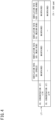
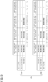
- FIG. 4 to FIG. 6 are reference tables LT1 to LT3 for use in a process (step ST14 in FIG. 3 ) for determining the ventilation rate.
- FIG. 4 is the reference table LT1 when SIm is "ventilation priority" (first mode).
- FIG. 5 is the reference table LT2 when SIm is “temperature adjustment priority” (second mode).
- FIG. 6 is the reference table LT3 when SIm is "balance control” (third mode).
- the main controller 55 adopts the type (breeze, weak wind, medium wind, or strong wind) designated by SIc as an initial value, and in the current control cycle which is the second or subsequent control cycle, determines the ventilation rate according to one of the reference tables LT1 to LT3 designated by SIm.
- the main controller 55 determines the ventilation rate for the current cycle using the reference table LT1 in FIG. 4 .
- the main controller 55 determines the ventilation rate for the current cycle using the reference table TL2 in FIG. 5 if SIm is temperature adjustment priority (second mode), and determines the ventilation rate of the current cycle using the reference table TL3 in FIG. 6 if SIm is balance control (third mode).
- “MAINTAINED” means that the current ventilation rate (ventilation rate determined in the previous cycle) is to be followed.
- the “rightward arrow” means that the current ventilation rate is to be increased by one stage in the current cycle, and the “leftward arrow” means that the current ventilation rate is to be decreased by one stage in the current cycle.
- TH is a threshold related to the CO2 concentration (CT), and is set to, for example, 1000 ppm. 1000 ppm is an example, and other values such as 1200 ppm may be used.
- ⁇ is a larger threshold margin for defining a threshold related to the blow-out temperature (TS), and is set to, for example, 3°C.
- ⁇ is a smaller threshold margin for defining a threshold related to the blow-out temperature (TS), and is set to, for example, 1°C. 3°C and 1°C are examples, and other values such as 4°C and 2° are acceptable.
- the reference table LT1 defines whether to maintain or change the current ventilation rate according to the numerical range of the CO2 concentration (CT).
- the data used for adjusting the ventilation rate includes CT which is the detection result of the CO2 sensor 80, but does not include TS which is the detection result of the supply air temperature sensor 24.
- the main controller 55 In the determination process using the reference table LT1, if the CO2 concentration (CT) ⁇ TH, the main controller 55 maintains the ventilation rate of the previous cycle for all ventilation rate types.
- the main controller 55 increases by one stage the previous cycle's breeze, weak wind, or medium wind and maintains the previous cycle's strong wind.
- the ventilation rate is determined only by the CT value without considering the TS value, for example, as illustrated in the reference table LT1 in FIG. 4 , if CT ⁇ TH, the ventilation rate can be controlled to increase except for the maximum ventilation rate (strong wind).
- the ventilation function of the ventilation system 1 can be prioritized.
- the reference table LT2 defines whether to maintain or change the ventilation rate with respect to the current state, according to the numerical range of the blow-out temperature (TS).
- the data used for adjusting the ventilation rate includes TS which is the detection result of the supply air temperature sensor 24, but does not include CT which is the detection result of the CO2 sensor 80.
- the reference table LT2 for temperature adjustment priority includes a reference table LT2a for cooling and a reference table LT2b for heating.
- the main controller 55 executes the following process according to the numerical range of TS.
- the previous cycle's breeze is maintained and the previous cycle's weak wind, medium wind, or strong wind is decreased by one stage.
- the previous cycle's breeze or weak wind is maintained, and the previous cycle's medium wind or strong wind is decreased by one stage.
- the previous cycle's breeze, weak wind, or medium wind is maintained, and the previous cycle's strong wind is decreased by one stage.
- the main controller 55 executes the following process according to the numerical range of TS. If TS ⁇ SIt ⁇ ⁇
- the previous cycle's breeze, weak wind, or medium wind is maintained, and the previous cycle's strong wind is decreased by one stage.
- the ventilation rate is determined only by the TS value without considering the CT value, for example, as illustrated in the reference table LT2 in FIG. 5 .
- the greater the degree of deviation of TS from SIt the greater the opportunity to decrease the ventilation rate, thereby enabling control to reduce the load on temperature adjustment.
- it is easier to indirectly adjust TS to the set temperature SIt and the temperature adjustment function of the ventilation system 1 can be prioritized.
- the reference table LT3 defines whether to maintain or change the ventilation rate with respect to the current state according to the numerical range of the CO2 concentration (CT) and the numerical range of the blow-out temperature (TS).
- CT CO2 concentration
- TS blow-out temperature
- the data used for adjusting the ventilation rate includes both the CT which is the detection result of the CO2 sensor 80 and the TS which is the detection result of the supply air temperature sensor 24.
- the reference table LT3 for balance control includes a reference table LT3a for cooling and a reference table LT3b for heating.
- the main controller 55 executes the following process according to the numerical ranges of CT and TS.
- the previous cycle's breeze is maintained and the previous cycle's weak wind, medium wind, and strong wind are decreased by one stage.
- the previous cycle's breeze or weak wind is maintained, and the previous cycle's medium wind or strong wind is decreased by one stage.
- the previous cycle's breeze, weak wind, or medium wind is maintained, and the previous cycle's strong wind is decreased by one stage.
- the previous cycle's breeze is increased by one stage, the previous cycle's weak wind is maintained, and the previous cycle's medium wind or strong wind is decreased by one stage.
- the previous cycle's breeze or weak wind is increased by one stage, the previous cycle's medium wind is maintained, and the previous cycle's strong wind is decreased by one stage.
- the previous cycle's breeze, weak wind, or medium wind is increased by one stage, and the previous cycle's strong wind is maintained.
- the main controller 55 executes the following process according to the numerical ranges of CT and TS.
- the previous cycle's breeze is maintained and the previous cycle's weak wind, medium wind, and strong wind are decreased by one stage.
- the previous cycle's breeze or weak wind is maintained, and the previous cycle's medium wind or strong wind is decreased by one stage.
- the previous cycle's breeze, weak wind, or medium wind is maintained, and the previous cycle's strong wind is decreased by one stage.
- the previous cycle's breeze is increased by one stage, the previous cycle's weak wind is maintained, and the previous cycle's medium wind or strong wind is decreased by one stage.
- the previous cycle's breeze or weak wind is increased by one stage, the previous cycle's medium wind is maintained, and the previous cycle's strong wind is decreased by one stage.
- the previous cycle's breeze, weak wind, or medium wind is increased by one stage, and the previous cycle's strong wind is maintained.
- control (the upper half of LT3a and LT3b) is performed to prioritize ventilation rate reduction in the same manner as the temperature adjustment priority, and if CT ⁇ TH, control (the lower half of LT3a and LT3b) is performed to change the rate of ventilation to be finally converged according to the numerical range of TS. Therefore, intermediate control that cannot be said to have a higher weighting for either CT or TS is performed.
- FIG. 7 is a flowchart illustrating an example of information processing of the air supply and exhaust controllers 25 and 44.
- each of the controllers 25 and 44 determines whether or not TVj has been received from the main controller 55 (step ST51), and if so, acquires AFj from the detection results of its own detector 23, 43 (step ST52).
- controllers 25 and 44 compare the magnitudes of AFj and TVj (step ST53), and execute the following process according to the comparison result.
- the air supply and exhaust controllers 25 and 44 autonomously adjust the rotational speed of their own fans 22 and 42 on the basis of the TVj received from the main controller 55 and the AFj that can be detected by their own detectors 23 and 43.
- a process (step ST14 in FIG. 3 ) for determining the ventilation rate is executed by the plurality of reference tables LT1 to LT3, but the main controller 55 may execute the process for determining the ventilation rate using, for example, the following Formula (1).
- the meaning of each parameter in Formula (1) is as described later.
- an "intervention mode” that responds to the detection of a very large CO2 concentration (CT) may be provided as a control mode of the main controller 55 not included in the SIm.
- the ventilation priority may be executed regardless of the SIm input to the input device 70.
- the CO2 sensor is exemplified as an example of the indoor monitoring sensor 80, but the monitoring sensor 80 may be, for example, the following sensors.
- the presence sensor it is only required to perform control to increase the ventilation rate in response to the detection of the presence of people, and in the case of adopting the number-of-people count sensor is adopted, it is only required to perform control to increase the ventilation rate when the number of people becomes a predetermined value or more.
- the monitoring sensor 80 that can be employed in the ventilation system 1 according to the present embodiment is not limited to the CO2 sensor, and may be any sensor that detects state information (such as CO2 concentration, particle concentration, odor level, presence or absence of people, and number of people), which is at least one of an indoor air state, the presence or absence of people indoors, and the number of people indoors.
- state information such as CO2 concentration, particle concentration, odor level, presence or absence of people, and number of people
- the input device 70 is of a type that, when installed in the management room, can limit the user who inputs SIm, which is the control mode type information, to a building manager or the like.
- the devices capable of limiting the users who inputs the control mode type information are not limited to the above, and for example, the following devices may be employed.
- both the number M of fans and the number N of fans may be two or more. Further, the number M of fans and the number N of fans may be different from each other.
- the number M of fans is two or more, it is sufficient if the total airflow of the M fans is set as the supply airflow to one room RM.
- the number N of fans is two or more, it is sufficient if the total airflow of the N fans is set as the exhaust airflow from one room RM.
- First mode A control mode having higher weighting on the state information CT, among the state information CT and the blow-out temperature TS that are usable for adjusting the indoor ventilation rate.
- the control mode uses the reference table LT1 in FIG. 4 or Formula (1) with A ⁇ B weighting.
- Second mode (temperature adjustment priority): A control mode having higher weighting on the blow-out temperature TS, among the state information CT and the blow-out temperature TS that are usable for adjusting the indoor ventilation rate.
- the control mode uses the reference table LT2 in FIG. 5 or Formula (1) with A > B weighting.
- the ventilation system 1 since the ventilation system 1 according to the present embodiment includes the input equipment 70 including the control mode type information SIm of the control modes as the setting information SI that can be input by a user, the user can set the ventilation system 1 whether to operate in the first mode or the second mode.
- the input equipment 70 is capable of limiting the user who inputs the type information SIm of the control modes.
- the user who inputs the type information of the control modes can be limited to, for example, a building manager.
- the control unit CU (specifically, the main controller 55) executes the first mode (ventilation priority) regardless of the control mode type information SIm input to the input equipment 70, if the detection result of the monitoring sensor 80 exceeds a predetermined threshold value. Therefore, it is possible to more quickly improve a deteriorated indoor environment (for example, CO2 concentration exceeding the reference amount) as compared with the case where the temperature adjustment priority or the balance control is continued.
- control unit CU (specifically, the main controller 55) is further capable of executing the third mode (balance control) for determining whether to decrease, maintain or increase the current ventilation rate on the basis of at least the detection result TS of the temperature sensor, the set value SIt of the blow-out temperature, the detection result CT of the monitoring sensor, and the set value TH of the state information. Therefore, it is possible to perform flexible operation in which ventilation function and temperature adjustment function are moderately balanced.
Landscapes
- Engineering & Computer Science (AREA)
- Combustion & Propulsion (AREA)
- Mechanical Engineering (AREA)
- General Engineering & Computer Science (AREA)
- Chemical & Material Sciences (AREA)
- Signal Processing (AREA)
- Physics & Mathematics (AREA)
- Fuzzy Systems (AREA)
- Mathematical Physics (AREA)
- Fluid Mechanics (AREA)
- Human Computer Interaction (AREA)
- Air Conditioning Control Device (AREA)
- Ventilation (AREA)
Abstract
Description
- The present disclosure relates to a ventilation system.
-
Patent Literature 1 discloses a ventilation system capable of first type ventilation. This ventilation system includes a heat exchanger, a supply air path and exhaust air path that allow the inside and outside of a target space to communicate with each other via the heat exchanger, an air supply fan that supplies air outside the target space to the target space via the supply air path, and an exhaust fan that exhausts air in the target space to the outside of the target space via the exhaust air path. - In the above ventilation system, the heat exchanger of the heat pump heat exchanger recovers heat from the return air in the indoor zone and then exhausts the heat to the outdoors, and uses the recovered heat for heat exchange with outside air from outdoors to supply the air to the indoor zone.
- PATENT LITERATURE 1:
Japanese Laid-Open Patent Publication No. 3-20573 - Conventional ventilation systems focus exclusively on heat recovery from the return air, and therefore are not designed to diversify control modes, such as prioritizing ventilation function in some situations and temperature adjustment function in other situations.
- An object of the present disclosure is to diversify control modes related to ventilation function and temperature adjustment function in a ventilation system capable of recovering heat from return air.
-
- (1) A ventilation system according to the present disclosure includes: a refrigerant circuit that circulates refrigerant through a compressor, a first heat exchanger, and a second heat exchanger; an air supply fan that draws outdoor air into an indoor space through the first heat exchanger; an exhaust fan that exhausts indoor air to an outdoor space through the second heat exchanger; a temperature sensor for detecting a blow-out temperature of the air supply fan; a monitoring sensor for detecting state information that is at least one of an indoor air state, presence or absence of people indoors, and number of people indoors; and a control unit that adjusts indoor ventilation rate. Types of control modes performed by the control unit (CU) include a first mode and a second mode described below.
- First mode: A control mode having higher weighting on the state information, among the state information and the blow-out temperature that are usable for adjusting the indoor ventilation rate.
- Second mode: A control mode having higher weighting on the blow-out temperature, among the state information and the blow-out temperature that are usable for adjusting the indoor ventilation rate.
- Since the ventilation system according to the present disclosure includes the above-described first mode and second mode as the types of the control modes performed by the control unit, it is possible to diversify the control modes related to ventilation function and temperature adjustment function in the ventilation system capable of recovering heat from return air.
- (2) The ventilation system according to the present disclosure may further include an input equipment including type information of the control modes as setting information that can be input by a user.
- In this case, the ventilation system includes the input equipment including the control mode type information as the setting information that can be input by the user, thereby allowing the user to set the ventilation system to operate in either the first mode or the second mode.
- (3) In the ventilation system according to the present disclosure, the input equipment may be capable of limiting the user who inputs the type information of the control modes.
- In this case, since the user who inputs the type information of the control modes can be limited to, for example, a building manager, it is possible to prevent the occupants of a room, which is the target space of the ventilation system, from arbitrarily changing the control modes.
- (4) In the ventilation system according to the present disclosure, the control unit may execute the first mode regardless of the control mode type information input to the input equipment, if a detection result of the monitoring sensor exceeds a predetermined threshold value.
- In this case, it is possible to more quickly improve a deteriorated indoor environment (for example, CO2 concentration exceeding the reference amount) as compared with the case where temperature adjustment priority or balance control is continued.
- (5) In the ventilation system according to the present disclosure, the control unit may be further capable of executing a third mode for determining whether to decrease, maintain, or increase the current ventilation rate on the basis of at least a detection result of the temperature sensor, a set value of the blow-out temperature, the detection result of the monitoring sensor, and a set value of the state information.
- In the ventilation system according to the present disclosure, the control unit is capable of executing the third mode for determining whether to decrease, maintain, or increase the current ventilation rate on the basis of at least the above four parameters. Thus, it is possible to perform flexible operation in which ventilation function and temperature adjustment function are moderately balanced.
-
-
FIG. 1 is a longitudinal sectional view of a building illustrating an example of the overall configuration of a ventilation system. -
FIG. 2 is a block diagram illustrating an example of the control system of a control unit. -
FIG. 3 is a flowchart illustrating an example of information processing of a main controller. -
FIG. 4 is a reference table when control mode type information is ventilation priority. -
FIG. 5 is a reference table when the control mode type information is temperature adjustment priority. -
FIG. 6 is a reference table when the control mode type information is balance control. -
FIG. 7 is a flowchart illustrating an example of information processing of air supply and exhaust controllers. -
FIG. 1 is a longitudinal sectional view of a building illustrating an example of the overall configuration of aventilation system 1. - In
FIG. 1 , reference signs "OA", "SA", "RA", and "EA" have the following meanings. -
- OA: Outdoor air (outside air). This is also the air that the
system 1 draws in from outdoors. - SA: Air (supply air) that the
system 1 sends indoors. - RA: Indoor air (return air). This is also the air that the
system 1 draws in from indoors. - EA: Air (exhaust air) that the
system 1 discharges outdoors. - The
ventilation system 1 according to the present embodiment provides first-type ventilation for an indoor target space RM while performing temperature adjustment for the supply air SA and heat recovery from the return air RA. The target space RM is, for example, the indoor space of various buildings such as an office building, a hospital, and a factory. - The target space RM is preferably an airtight room for a predetermined use, but may be, for example, an indoor corridor, a staircase, an entrance, or the like. Furthermore, in the target space RM, an
indoor unit 2 of an air conditioning system separate from theventilation system 1 may be installed. - As illustrated in
FIG. 1 , theventilation system 1 includes aheat exchange unit 10 on the utilization side (air supply side), anair supply unit 20, aheat exchange unit 30 on the recovery side (exhaust side), anexhaust unit 40, acompressor unit 50, and arefrigerant circuit 60. - The
heat exchange unit 10 and theair supply unit 20 are installed in the ceiling space of the target space RM, and theheat exchange unit 30, theexhaust unit 40, and thecompressor unit 50 are installed inside the wall of the target space RM. - The
ventilation system 1 further includes aninput device 70 that is an input equipment allowing users to input operations, and amonitoring sensor 80. Theinput device 70 is, for example, a remote controller attached to the wall surface of the target space RM. Theinput device 70 may be installed in a room different from the target space RM, such as a management room (not illustrated). - The
monitoring sensor 80 monitors an indoor air state, and is capable of wired or wireless communication conforming to a predetermined communication standard. In the present embodiment, themonitoring sensor 80 is assumed to be a CO2 sensor that is attached to the ceiling surface of the target space RM and that detects CO2 concentration. - The installation position of each unit illustrated in
FIG. 1 is an example, and for example, theheat exchange unit 30 and theexhaust unit 40 may be arranged in the ceiling space, and the return air RA may be drawn in from the ceiling side. - Alternatively, at least one of the
heat exchange unit 30, theexhaust unit 40, and thecompressor unit 50 may be installed outdoors. - The
heat exchange unit 10 on the utilization side has acasing 11 and a plurality of devices housed in thecasing 11. The plurality of devices includes a utilization-side heat exchanger (hereinafter referred to as "first heat exchanger") 12, which is an element device of therefrigerant circuit 60, and an outsideair temperature sensor 13. - The
first heat exchanger 12 is, for example, a cross-fin tube or microchannel heat exchanger, and exchanges heat between the refrigerant flowing inside thefirst heat exchanger 12 and the outside air OA. - The
air supply unit 20 has acasing 21 and a plurality of devices housed in thecasing 21. The plurality of devices includes anair supply fan 22, anair supply detector 23, a supplyair temperature sensor 24, and anair supply controller 25. - The
air supply fan 22 is, for example, a centrifugal fan with controllable fan speed. Theair supply detector 23 is, for example, an airflow sensor for detecting airflow, or a sensor for detecting air velocity, differential pressure, fan speed, or the like (hereinafter referred to as "airflow equivalent"), which are physical quantities from which the airflow is calculated. Therefore, if theair supply controller 25 has the function of counting the fan speed, theair supply controller 25 also serves as theair supply detector 23. - The
air supply controller 25 is, for example, a control module including a circuit board and an integrated circuit such as a central processing unit (CPU) and memory mounted on the circuit board. The integrated circuit may include at least a field-programmable gate array (FPGA) or an application-specific IC (ASIC). - The
air supply controller 25 is capable of performing communication control with other controllers and sensors conforming to a predetermined communication standard and of performing predetermined information processing such as control for adjusting the fan speed so that the airflow of theair supply fan 22 becomes a target value. - The
heat exchange unit 30 on the recovery side has acasing 31 and a plurality of devices housed in thecasing 31. The plurality of devices includes a recovery-side heat exchanger (hereinafter referred to as "second heat exchanger") 32, which is an element device of therefrigerant circuit 60, and a returnair temperature sensor 33. - The
second heat exchanger 32 is, for example, a cross-fin tube or microchannel heat exchanger, and exchanges heat between the refrigerant flowing inside thesecond heat exchanger 32 and the return air RA. - The
exhaust unit 40 has acasing 41 and a plurality of devices housed in thecasing 41. The plurality of devices includes anexhaust fan 42, anexhaust detector 43, and anexhaust controller 44. - The
exhaust fan 42 is, for example, a centrifugal fan with controllable fan speed. Theexhaust detector 43 is, for example, an airflow sensor for detecting airflow or a sensor for detecting the airflow equivalent. Therefore, if theexhaust controller 44 has the function of counting the fan speed, theexhaust controller 44 also serves as theexhaust detector 43. - The
exhaust controller 44 is, for example, a control module including a circuit board and an integrated circuit such as a CPU and memory mounted on the circuit board. The integrated circuit may include at least the FPGA or the ASIC. - The
exhaust controller 44 is capable of performing communication control with other controllers and sensors conforming to a predetermined communication standard and of performing predetermined information processing such as control for adjusting the fan speed so that the airflow of theexhaust fan 42 becomes a target value. - The
compressor unit 50 includes acasing 51 and a plurality of devices housed in thecasing 51. The plurality of devices includes acompressor 52, a four-way valve 53, anexpansion valve 54, and amain controller 55. - The
refrigerant circuit 60 circulates refrigerant through thecompressor 52, thefirst heat exchanger 12, and thesecond heat exchanger 32, and has thecompressor 52, the four-way valve 53, theexpansion valve 54, thefirst heat exchanger 12, thesecond heat exchanger 32, and arefrigerant pipe 61 that connects these components. - The
main controller 55 is, for example, a control module including a circuit board and an integrated circuit such as a CPU and memory mounted on the circuit board. The integrated circuit may include at least the FPGA or the ASIC. - The
main controller 55 is capable of performing communication control with other controllers and sensors conforming to a predetermined communication standard and of performing predetermined information processing such as determination of a controlled variable for therefrigerant circuit 60 according to the ventilation rate. - In the ceiling space of the target space RM, the suction port of the
casing 11 communicates with an air supply port outdoors through a duct d1. - In the ceiling space of the target space RM, the suction port of the
casing 21 is airtightly connected to the blow-out port of thecasing 11 by a duct d2. The blow-out port of thecasing 21 is exposed from the ceiling surface to the target space RM. - Therefore, the air path formed by the duct d1, the
casing 11, the duct d2, and thecasing 21 connects the outdoors to the indoors, and constitutes an "air supply path" in which thefirst heat exchanger 12 and theair supply fan 22 are disposed. - Note that a blow-out unit (not illustrated) having a filter, a wind direction plate, and the like may be coupled to the blow-out side of the
casing 21 via a duct or directly, and the blowing unit may be exposed from the ceiling surface to the target space RM. In addition, a humidifying unit or a filter unit (not illustrated) that collects microparticles (such as PM 2.5) may be provided at points on the ducts d1 and d2. In this case, the casing of each of the above units may also be a component of the air supply path. - Under the floor of the target space RM, the suction port of the
casing 31 is airtightly connected to the air supply port in the floor surface by a duct d3 including a branch pipe. - Inside the wall of the target space RM, the suction port of the
casing 41 is airtightly connected to the blow-out port of thecasing 31 by a duct d4. The blow-out port of thecasing 41 communicates with an exhaust port outdoors through a duct d5. - Therefore, the air path formed by the duct d3, the
casing 31, the duct d4, thecasing 41, and the duct d5 connects the outdoors to the indoors, and constitutes an "exhaust air path" in which thesecond heat exchanger 32 and theexhaust fan 42 are disposed. - When the
air supply fan 22 is driven, the duct d1, thecasing 11, and the duct d2 in the air supply path become negative pressure, and the outside air OA is drawn into the duct d1. - At this time, the outside
air temperature sensor 13 detects the temperature of the outside air OA before heat exchange with thefirst heat exchanger 12. The air after heat exchange with thefirst heat exchanger 12 passes through the duct d2 and thecasing 21 and is delivered indoors as the supply air SA. At this time, the supplyair temperature sensor 24 detects the temperature of the supply air SA. - When the
exhaust fan 42 is driven, the duct d4, thecasing 31, and the duct d3 in the exhaust air path become negative pressure, and the return air RA is drawn into the duct d3. - At this time, the return
air temperature sensor 33 detects the temperature of the return air RA before heat exchange with thesecond heat exchanger 32. The air after the heat exchange with thesecond heat exchanger 32 passes through thecasing 41 and the duct d5 and is delivered outdoors as the exhaust air EA. - In the
ventilation system 1 inFIG. 1 , the supply air path may be configured such that theheat exchange unit 10 is located on the blow-out side (downstream side in the air supply direction) of theair supply unit 20. Similarly, the exhaust air path may be configured such that theheat exchange unit 30 is located on the blow-out side (downstream side in the exhaust direction) of theexhaust unit 40. - In the
ventilation system 1 inFIG. 1 , theheat exchange unit 10 and theair supply unit 20 may be an integrated unit housed in the same casing. Similarly, theheat exchange unit 30 and theexhaust unit 40 may be an integrated unit housed in the same casing. - The
compressor 52 is an element device of therefrigerant circuit 60, sucking in low-pressure gaseous refrigerant and discharging high-pressure gaseous refrigerant. - The
compressor 52 is, for example, a variable displacement type (variable capacity type), the displacement of which is variable by the inverter control of an electric motor. However, thecompressor 52 may be of a constant-displacement type or two ormore compressors 52 may be connected in parallel. - The
expansion valve 54 is, for example, an electric valve for adjusting the flow rate and pressure of the refrigerant in thepipe 61. The refrigerant pressure to thefirst heat exchanger 12 is adjusted by controlling the opening degree of theexpansion valve 54. - The four-
way valve 53 reverses the flow direction of the refrigerant in the circuit, and switches the refrigerant discharged fromcompressor 52 to eitherfirst heat exchanger 12 orsecond heat exchanger 32. Therefore, the temperature adjustment operation that can be executed by theventilation system 1 includes "cold air supply" (cooling) in which the outside air OA is cooled and supplied indoors, and "warm air supply" (heating) in which the outside air OA is heated and supplied indoors. - Specifically, in the case of cold air supply in which cold air obtained by cooling the outside air OA is used as the supply air SA, the four-
way valve 53 is maintained in the state indicated by the solid line inFIG. 1 . - In this case, the
first heat exchanger 12 on the utilization side functions as an evaporator and cools the outside air OA, and thesecond heat exchanger 32 on the recovery side functions as a condenser and heats the return air RA. The heating of the return air RA corresponds to heat recovery from the return air RA. - Meanwhile, in the case of the warm air supply in which warm air obtained by heating the outside air OA is used as the supply air SA, the four-
way valve 53 is maintained in the state indicated by the broken line inFIG. 1 . - In this case, the
first heat exchanger 12 on the utilization side functions as a condenser and heats the outside air OA, and thesecond heat exchanger 32 on the recovery side functions as an evaporator and cools the return air RA. The cooling of the return air RA corresponds to heat recovery from the return air RA. - In the
ventilation system 1 according to the present embodiment, the four-way valve 53 of therefrigerant circuit 60 may be omitted. In this case, thefirst heat exchanger 12 is used only as either an evaporator or a condenser, resulting in theventilation system 1 that performs only the cold air supply or the warm air supply. -
FIG. 2 is a block diagram illustrating an example of the control system of theventilation system 1. - The meanings of the parameters included in
FIG. 2 are as follows. - SI: Setting information that can be input to the
input device 70. SI includes the following SIm, SIt, and SIc. - SIm: Control mode type information (such as ventilation priority, temperature adjustment priority, and balance control)
- SIt: Set temperature of the supply air SA (set value of blow-out temperature)
- SIc: Ventilation rate type information defined in stages (such as "breeze", "weak wind", "medium wind", and "strong wind", or identification numbers from "
level 1" to "level 4") - Note that in the present embodiment, there are four types of ventilation rate: breeze, weak wind, medium wind, and strong wind, which correspond to the ratio (%) to the rated airflow (m3/h) of the
air supply fan 22. - Furthermore, the memory of the
main controller 55 holds a reference table that defines the correspondence relationship between the type of ventilation rate (%) and the target value TV1 of supply airflow (m3/h), to perform control to equally balance the supply airflow (m3/h) and the exhaust airflow (m3/h). -
- TS: Detection result of the supply air temperature sensor 24 (blow-out temperature of the air supply fan: supply air temperature)
- TO: Detection result of the outside air temperature sensor 13 (outside air temperature)
- TR: Detection result of the return air temperature sensor 33 (return air temperature)
- AF1: Airflow (supply airflow) blown out by the
air supply fan 22 - However, if the
air supply detector 23 is an airflow sensor, AF1 is the detection result of the sensor, and if theair supply detector 23 is a sensor that detects an airflow equivalent, AF1 is the airflow calculated from the detection result of the sensor. AF1 may be the airflow calculated from the fan speed counted by theair supply controller 25. - AF2: Airflow (exhaust airflow) blown out by the
exhaust fan 42 - However, if the
exhaust detector 43 is an airflow sensor, AF2 is the detection result of the sensor, and if theexhaust detector 43 is a sensor that detects an airflow equivalent, AF2 is the airflow calculated from the detection result of the sensor. AF2 may be the airflow calculated from the fan speed counted by theexhaust controller 44. -
- CT: Detection result of the CO2 sensor 80 (CO2 concentration in the target space RM)
- TV1: Target value of airflow (supply airflow) blown out by the
air supply fan 22 - TV2: Target value of airflow (exhaust airflow) blown out by the
exhaust fan 42 - CQ: Controlled variable (compressor discharge amount, refrigerant flow rate or direction, and the like) for the
refrigerant circuit 60 - The mode names (ventilation priority, temperature adjustment priority, and balance control) of the SIm described above are just examples, and can be any mode name that can substantially identify the following control contents.
- First mode: A control mode having higher weighting on the state information CT, among the state information CT and the blow-out temperature TS that are usable for adjusting the indoor ventilation rate. For example, "ventilation priority" based only on CT, using the reference table in
FIG. 4 described later, is a type of the first mode. - Second mode: A control mode having higher weighting on the blow-out temperature TS, among the state information CT and the blow-out temperature TS that are usable for adjusting the indoor ventilation rate. For example, "temperature adjustment priority" based only on TS, using the reference table in
FIG. 5 described later, is a type of the second mode. - Third mode: An intermediate control mode in which, among the state information CT and the blow-out temperature TS that can be used to adjust the indoor ventilation rate, neither the state information CT nor the blow-out temperature TS has a higher weighting. For example, "balance priority" using the reference table in
FIG. 6 described later is a type of the third mode. - As illustrated in
FIG. 2 , the control system of theventilation system 1 includes a control unit CU composed of a group of controllers that perform wired or wireless communication. The control unit CU includes themain controller 55, theair supply controller 25, and theexhaust controller 44. - The
main controller 55 is connected to theinput device 70. When the user inputs SI to theinput device 70, theinput device 70 transmits the SI to themain controller 55. Themain controller 55 records the received SI in its own memory. - The
main controller 55 is connected to each of the temperature-relatedsensors main controller 55 receives TS, TO, and TR from thesensors - If the supply
air temperature sensor 24 is connected to theair supply controller 25, the TS may be transmitted to themain controller 55 with theair supply controller 25 as a relay node. - The
main controller 55 is connected to theair supply controller 25, a second controller 25B, and theexhaust controller 44. - Upon determining TV1, the
main controller 55 transmits the determined TV1 to theair supply controller 25, and upon determining TV2, themain controller 55 transmits the determined TV2 to theexhaust controller 44. - The
main controller 55 is connected to thecompressor 52, the four-way valve 53, and theexpansion valve 54. Upon determining CQ, themain controller 55 outputs the determined CQ to at least one of thecompressor 52, the four-way valve 53, and theexpansion valve 54. - The
air supply controller 25 is connected to theair supply fan 22, theair supply detector 23, and theCO2 sensor 80. - The
air supply controller 25 transfers the CT received from theCO2 sensor 80 to themain controller 55. If theCO2 sensor 80 is connected to themain controller 55, PR is directly transmitted to themain controller 55. - If the
air supply detector 23 is an airflow sensor, theair supply controller 25 sets the detection result received from thedetector 23 as AF1. - If the
air supply detector 23 is an airflow equivalent sensor, theair supply controller 25 calculates AF1 from the detection result received from thedetector 23. Theair supply controller 25 may set the airflow calculated from the fan speed counted by itself as AF1. - Upon receiving the TV1, the
air supply controller 25 calculates fan speed on the basis of the TV1 and the AF1, and outputs the calculated speed to theair supply fan 22. - The
exhaust controller 44 is connected to theexhaust fan 42 and theexhaust detector 43. - If the
exhaust detector 43 is an airflow sensor, theexhaust controller 44 sets the detection result received from thedetector 43 as AF2. - If the
exhaust detector 43 is an airflow equivalent sensor, theexhaust controller 44 calculates AF2 from the detection result received from thedetector 43. Theexhaust controller 44 may set the airflow calculated from the fan speed counted by itself as AF2. - Upon receiving the TV2, the
exhaust controller 44 calculates the fan speed on the basis of theTV 2 and the AF2, and outputs the calculated speed to theexhaust fan 42. -
FIG. 3 is a flowchart illustrating an example of information processing of themain controller 55. - As illustrated in
FIG. 3 , themain controller 55 reads the latest setting information SI from the memory after startup (step ST11). - The setting information SI includes SIc that is the setting information of ventilation rate, SIt that is the set temperature of the supply air SA, and SIm that is the setting information of control mode type.
- Next, the
main controller 55 acquires TS, TO, and TR, which are detection results related to temperature (step ST12), and CT, which is the detection result of CO2 concentration in the target space RM (step ST13). - Next, the
main controller 55 executes a ventilation rate determination process (step ST14). The content of the ventilation rate determination process varies depending on the type of control mode, and will be described later. - Next, the
main controller 55 calculates, from the determined ventilation rate, TV1 that is a target value of the supply airflow and TV2 that is a target value of the exhaust airflow (step ST15). - For example, the
main controller 55 reads the supply airflow corresponding to the determined ventilation rate (%) from the reference table, and sets the read airflow as TV1. Furthermore, if air supply and exhaust are to be balanced, themain controller 55 sets TV2 = TV1. - Next, the
main controller 55 executes a process for calculating CQ, which is a controlled variable for the refrigerant circuit 60 (step ST16). This calculation process calculates CQ on the basis of the TV1 and TV2 determined in the current control cycle. - For example, the
main controller 55 calculates a temperature adjustment load for bringing the supply air SA to the set temperature SIt from the TV1 and TV2 determined in the current control cycle and the current TS, TO, and TR, and determines CQ, which is a controlled variable for therefrigerant circuit 60, on the basis of the calculated temperature control load. - Next, the
main controller 55 transmits the determined TV1 and TV2 to thecontrollers - Specifically, the
main controller 55 transmits the TV1 to theair supply controller 25, and transmits the TV2 to theexhaust controller 44. - Next, the
main controller 55 controls therefrigerant circuit 60 with the CQ determined in the step ST15 (step ST18), and determines whether or not a predetermined control cycle (for example, 30 seconds) has elapsed (step ST19). - If the determination result in the step ST19 is positive, the
main controller 55 returns the process to before the step ST11. - If the determination result in the step ST19 is negative, the
main controller 55 determines the presence or absence of a termination command from the input device 70 (step ST20). - If the determination result in the step ST20 is negative, the
main controller 55 returns the process to before the ST19. If the determination result in step ST19 is positive, themain controller 55 terminates the process. -
FIG. 4 to FIG. 6 are reference tables LT1 to LT3 for use in a process (step ST14 inFIG. 3 ) for determining the ventilation rate. - Specifically,
FIG. 4 is the reference table LT1 when SIm is "ventilation priority" (first mode).FIG. 5 is the reference table LT2 when SIm is "temperature adjustment priority" (second mode).FIG. 6 is the reference table LT3 when SIm is "balance control" (third mode). - In the first control cycle after startup, the
main controller 55 adopts the type (breeze, weak wind, medium wind, or strong wind) designated by SIc as an initial value, and in the current control cycle which is the second or subsequent control cycle, determines the ventilation rate according to one of the reference tables LT1 to LT3 designated by SIm. - Specifically, if SIm is ventilation priority (first mode), the
main controller 55 determines the ventilation rate for the current cycle using the reference table LT1 inFIG. 4 . - Similarly, the
main controller 55 determines the ventilation rate for the current cycle using the reference table TL2 inFIG. 5 if SIm is temperature adjustment priority (second mode), and determines the ventilation rate of the current cycle using the reference table TL3 inFIG. 6 if SIm is balance control (third mode). - In
FIG. 4 to FIG. 6 , "MAINTAINED" means that the current ventilation rate (ventilation rate determined in the previous cycle) is to be followed. In addition, the "rightward arrow" means that the current ventilation rate is to be increased by one stage in the current cycle, and the "leftward arrow" means that the current ventilation rate is to be decreased by one stage in the current cycle. - "TH" is a threshold related to the CO2 concentration (CT), and is set to, for example, 1000 ppm. 1000 ppm is an example, and other values such as 1200 ppm may be used.
- "α" is a larger threshold margin for defining a threshold related to the blow-out temperature (TS), and is set to, for example, 3°C. "β" is a smaller threshold margin for defining a threshold related to the blow-out temperature (TS), and is set to, for example, 1°C. 3°C and 1°C are examples, and other values such as 4°C and 2° are acceptable.
- As illustrated in
FIG. 4 , the reference table LT1 defines whether to maintain or change the current ventilation rate according to the numerical range of the CO2 concentration (CT). - Therefore, in the ventilation priority in
FIG. 4 , which is an example of the first mode, the data used for adjusting the ventilation rate includes CT which is the detection result of theCO2 sensor 80, but does not include TS which is the detection result of the supplyair temperature sensor 24. - In the determination process using the reference table LT1, if the CO2 concentration (CT) < TH, the
main controller 55 maintains the ventilation rate of the previous cycle for all ventilation rate types. - In the determination process using the reference table LT1, if the CO2 concentration (CT) ≥ TH, the
main controller 55 increases by one stage the previous cycle's breeze, weak wind, or medium wind and maintains the previous cycle's strong wind. - As described above, in the ventilation-priority control mode, since the ventilation rate is determined only by the CT value without considering the TS value, for example, as illustrated in the reference table LT1 in
FIG. 4 , if CT ≥ TH, the ventilation rate can be controlled to increase except for the maximum ventilation rate (strong wind). - Therefore, if rapid ventilation is required due to a high CO2 concentration, the ventilation function of the
ventilation system 1 can be prioritized. - As illustrated in
FIG. 5 , the reference table LT2 defines whether to maintain or change the ventilation rate with respect to the current state, according to the numerical range of the blow-out temperature (TS). - Therefore, in the temperature adjustment priority in
FIG. 5 which is an example of the second mode, the data used for adjusting the ventilation rate includes TS which is the detection result of the supplyair temperature sensor 24, but does not include CT which is the detection result of theCO2 sensor 80. The reference table LT2 for temperature adjustment priority includes a reference table LT2a for cooling and a reference table LT2b for heating. - In the determination process according to the reference table LT2a, the
main controller 55 executes the following process according to the numerical range of TS. - If SIt + α ≤ TS:
- The previous cycle's breeze is maintained and the previous cycle's weak wind, medium wind, or strong wind is decreased by one stage.
- If SIt + β ≤ TS < SIt + α:
- The previous cycle's breeze or weak wind is maintained, and the previous cycle's medium wind or strong wind is decreased by one stage.
- If TS < SIt + β:
- The previous cycle's breeze, weak wind, or medium wind is maintained, and the previous cycle's strong wind is decreased by one stage.
- In the determination process according to the reference table LT2b, the
main controller 55 executes the following process according to the numerical range of TS.
- The previous cycle's breeze is maintained and the previous cycle's weak wind, medium wind, or strong wind is decreased by one stage.

- The previous cycle's breeze and weak wind are maintained, and the previous cycle's medium wind or strong wind is decreased by one stage.

- The previous cycle's breeze, weak wind, or medium wind is maintained, and the previous cycle's strong wind is decreased by one stage.
- As described above, in the temperature-priority control mode, since the ventilation rate is determined only by the TS value without considering the CT value, for example, as illustrated in the reference table LT2 in
FIG. 5 , the greater the degree of deviation of TS from SIt, the greater the opportunity to decrease the ventilation rate, thereby enabling control to reduce the load on temperature adjustment. Thus, it is easier to indirectly adjust TS to the set temperature SIt, and the temperature adjustment function of theventilation system 1 can be prioritized. - As illustrated in
FIG. 6 , the reference table LT3 defines whether to maintain or change the ventilation rate with respect to the current state according to the numerical range of the CO2 concentration (CT) and the numerical range of the blow-out temperature (TS). - Therefore, in the balance control in
FIG. 6 which is an example of the third mode, the data used for adjusting the ventilation rate includes both the CT which is the detection result of theCO2 sensor 80 and the TS which is the detection result of the supplyair temperature sensor 24. The reference table LT3 for balance control includes a reference table LT3a for cooling and a reference table LT3b for heating. - In the determination process according to the reference table LT3a, the
main controller 55 executes the following process according to the numerical ranges of CT and TS. - IfCT < TH and SIt + α ≤ TS:
- The previous cycle's breeze is maintained and the previous cycle's weak wind, medium wind, and strong wind are decreased by one stage.
- If CT < TH and SIt + β ≤ TS < SIt + α:
- The previous cycle's breeze or weak wind is maintained, and the previous cycle's medium wind or strong wind is decreased by one stage.
- If CT < TH and TS < SIt + β:
- The previous cycle's breeze, weak wind, or medium wind is maintained, and the previous cycle's strong wind is decreased by one stage.
-
- If CT ≥ TH and SIt + α ≤ TS:
- The previous cycle's breeze is increased by one stage, the previous cycle's weak wind is maintained, and the previous cycle's medium wind or strong wind is decreased by one stage.
- If CT ≥ TH and SIt + β ≤ TS < SIt + α:
- The previous cycle's breeze or weak wind is increased by one stage, the previous cycle's medium wind is maintained, and the previous cycle's strong wind is decreased by one stage.
- IfCT ≥ TH and TS < SIt + β:
- The previous cycle's breeze, weak wind, or medium wind is increased by one stage, and the previous cycle's strong wind is maintained.
- In the determination process according to the reference table LT3b, the
main controller 55 executes the following process according to the numerical ranges of CT and TS. - If CT < TH and TS < SIt - α:
- The previous cycle's breeze is maintained and the previous cycle's weak wind, medium wind, and strong wind are decreased by one stage.
- If CT < TH and SIt - α ≤ TS < SIt - β:
- The previous cycle's breeze or weak wind is maintained, and the previous cycle's medium wind or strong wind is decreased by one stage.
- IfCT < TH and SIt - β ≤ TS:
- The previous cycle's breeze, weak wind, or medium wind is maintained, and the previous cycle's strong wind is decreased by one stage.
-
- If CT ≥ TH and TS < SIt - α:
- The previous cycle's breeze is increased by one stage, the previous cycle's weak wind is maintained, and the previous cycle's medium wind or strong wind is decreased by one stage.
- If CT ≥ TH and SIt - α ≤ TS < SIt - β:
- The previous cycle's breeze or weak wind is increased by one stage, the previous cycle's medium wind is maintained, and the previous cycle's strong wind is decreased by one stage.
- If CT ≥ TH and SIt - β ≤ TS:
- The previous cycle's breeze, weak wind, or medium wind is increased by one stage, and the previous cycle's strong wind is maintained.
- As described above, in the control mode of balance control, for example, as illustrated in the reference table LT3 in
FIG. 6 , if CT < TH, control (the upper half of LT3a and LT3b) is performed to prioritize ventilation rate reduction in the same manner as the temperature adjustment priority, and if CT ≥ TH, control (the lower half of LT3a and LT3b) is performed to change the rate of ventilation to be finally converged according to the numerical range of TS. Therefore, intermediate control that cannot be said to have a higher weighting for either CT or TS is performed. - This allows for flexible operation in which the ventilation function and temperature adjustment function of the
ventilation system 1 are moderately balanced. -
FIG. 7 is a flowchart illustrating an example of information processing of the air supply andexhaust controllers - In
FIG. 7 , the suffix "j" is an identification number representing air supply or exhaust. j=1 means air supply and j=2 means exhaust. Therefore,FIG. 7 represents the information processing of theair supply controller 25 when j=1, and represents the information processing of theexhaust controller 44 when j=2. - As illustrated in
FIG. 7 , after startup, each of thecontrollers own detector 23, 43 (step ST52). - Next, the
controllers - That is, if AFj < TVj, each of the
controllers own fan - In this manner, the air supply and
exhaust controllers own fans main controller 55 and the AFj that can be detected by theirown detectors - In the above-described embodiment, a process (step ST14 in
FIG. 3 ) for determining the ventilation rate is executed by the plurality of reference tables LT1 to LT3, but themain controller 55 may execute the process for determining the ventilation rate using, for example, the following Formula (1). However, the meaning of each parameter in Formula (1) is as described later.
-
- QV: Ventilation rate (target value of supply airflow)
- A: Weight coefficient that defines the degree of influence of the deviation of blow-out temperature from the set value on the ventilation rate
- B: Weight coefficient that defines the degree of influence of the deviation of CO2 concentration from the set value on the ventilation rate
- C (SIt, TH): Function representing the ventilation rate when the blow-out temperature and the CO2 concentration are set values
- TS: blow-out temperature (detection result of the air supply fan 22)
- SIt: Set temperature (set value)
- CT: CO2 concentration (detection result of the CO2 sensor 80)
- TH: CO2 concentration threshold (set value)
- In this case, it is sufficient to analyze the function C (SIt, TH) in Formula (1) by experiment, an air conditioning simulator, or the like.
- For the coefficients A and B, in the case of the first mode (ventilation priority), it is sufficient to determine the numerical values of A and B so that the weighting is A < B (A=0 is also acceptable). Furthermore, in the case of the second mode (temperature adjustment priority), it is sufficient to determine the numerical values of A and B so that the weighting is A > B (B=0 is also acceptable).
- In the above-described embodiment, an "intervention mode" that responds to the detection of a very large CO2 concentration (CT) may be provided as a control mode of the
main controller 55 not included in the SIm. - Specifically, if CT, which is the detection result of the
monitoring sensor 80, exceeds a predetermined threshold value (for example, 1500 ppm) greater than TH, the ventilation priority may be executed regardless of the SIm input to theinput device 70. - In the above-described embodiment, the CO2 sensor is exemplified as an example of the
indoor monitoring sensor 80, but themonitoring sensor 80 may be, for example, the following sensors. - 1) Suspended particle sensor: a sensor that detects the concentration of suspended particles such as smoke and dust
- 2) Odor sensor: a sensor that detects the degree of indoor odor
- 3) Presence sensor: a sensor that detects the presence or absence of people in a room
- 4) Number-of-people count sensor: a sensor that detects the number of people in a room
- In the case of adopting the suspended particle sensor, it is only required to perform control to increase the ventilation rate when the particle concentration becomes a predetermined value or more, and in the case of adopting the odor sensor, it is only required to perform control to increase the ventilation rate when the degree of odor becomes a predetermined value or more.
- Similarly, in the case of adopting the presence sensor, it is only required to perform control to increase the ventilation rate in response to the detection of the presence of people, and in the case of adopting the number-of-people count sensor is adopted, it is only required to perform control to increase the ventilation rate when the number of people becomes a predetermined value or more.
- As described above, the
monitoring sensor 80 that can be employed in theventilation system 1 according to the present embodiment is not limited to the CO2 sensor, and may be any sensor that detects state information (such as CO2 concentration, particle concentration, odor level, presence or absence of people, and number of people), which is at least one of an indoor air state, the presence or absence of people indoors, and the number of people indoors. - In the above-described embodiment, the
input device 70 is of a type that, when installed in the management room, can limit the user who inputs SIm, which is the control mode type information, to a building manager or the like. - However, the devices capable of limiting the users who inputs the control mode type information are not limited to the above, and for example, the following devices may be employed.
-
- 1) Dip switches mounted on the circuit boards or the like of the
main controller 55 - 2) Dedicated switches provided on the control panel of the
compressor unit 50 - 3) A
remote controller 70 that requires password input to launch an SIm input screen - 4) A communication terminal (laptop PC, tablet PC, smartphone, or the like) that communicates with the
main controller 55 via a dedicated line - 5) A communication terminal (laptop PC, tablet PC, smartphone, or the like) that can communicate with the
main controller 55 over a public line and requires password input before setting SIm - The above-described embodiment exemplifies the configuration of the air path in which M = N = 1, where M is the number of fans on the air supply side for one room RM and N is the number of fans on the exhaust side. However, both the number M of fans and the number N of fans may be two or more. Further, the number M of fans and the number N of fans may be different from each other.
- If the number M of fans is two or more, it is sufficient if the total airflow of the M fans is set as the supply airflow to one room RM.
- In addition, if the number N of fans is two or more, it is sufficient if the total airflow of the N fans is set as the exhaust airflow from one room RM.
-
- (1) Since the
ventilation system 1 according to the present embodiment includes the following first mode and second mode as the types of control modes performed by the control unit CU (specifically, the main controller 55), it is possible to diversify the control modes related to ventilation function and temperature adjustment function in theventilation system 1 capable of recovering heat from the return air. - First mode (ventilation priority): A control mode having higher weighting on the state information CT, among the state information CT and the blow-out temperature TS that are usable for adjusting the indoor ventilation rate. For example, the control mode uses the reference table LT1 in
FIG. 4 or Formula (1) with A < B weighting. - Second mode (temperature adjustment priority): A control mode having higher weighting on the blow-out temperature TS, among the state information CT and the blow-out temperature TS that are usable for adjusting the indoor ventilation rate. For example, the control mode uses the reference table LT2 in
FIG. 5 or Formula (1) with A > B weighting. - (2) Since the
ventilation system 1 according to the present embodiment includes theinput equipment 70 including the control mode type information SIm of the control modes as the setting information SI that can be input by a user, the user can set theventilation system 1 whether to operate in the first mode or the second mode. - (3) In the
ventilation system 1 according to the present embodiment, theinput equipment 70 is capable of limiting the user who inputs the type information SIm of the control modes. Thus, the user who inputs the type information of the control modes can be limited to, for example, a building manager. - Therefore, it is possible to prevent the occupants of a room, which is the target space RM of the
ventilation system 1, from arbitrarily changing the control modes. - (4) In the
ventilation system 1 according to the present embodiment, the control unit CU (specifically, the main controller 55) executes the first mode (ventilation priority) regardless of the control mode type information SIm input to theinput equipment 70, if the detection result of themonitoring sensor 80 exceeds a predetermined threshold value. Therefore, it is possible to more quickly improve a deteriorated indoor environment (for example, CO2 concentration exceeding the reference amount) as compared with the case where the temperature adjustment priority or the balance control is continued. - (5) In the
ventilation system 1 according to the present embodiment, the control unit CU (specifically, the main controller 55) is further capable of executing the third mode (balance control) for determining whether to decrease, maintain or increase the current ventilation rate on the basis of at least the detection result TS of the temperature sensor, the set value SIt of the blow-out temperature, the detection result CT of the monitoring sensor, and the set value TH of the state information. Therefore, it is possible to perform flexible operation in which ventilation function and temperature adjustment function are moderately balanced. - The present disclosure is not limited to the above exemplification, but is defined by claims, and is intended to include all modifications within the meaning and scope equivalent to the claims.
-
- 1
- ventilation system
- 12
- first heat exchanger
- 20
- air supply unit
- 22
- air supply fan
- 23
- air supply detector
- 24
- supply air temperature sensor
- 25
- air supply controller
- 32
- second heat exchanger
- 33
- return air temperature sensor
- 40
- exhaust unit
- 42
- exhaust fan
- 43
- exhaust detector
- 44
- exhaust controller
- 52
- compressor
- 53
- four-way valve
- 54
- expansion valve
- 55
- main controller
- 60
- refrigerant circuit
- 61
- refrigerant pipe
- 70
- input device (remote controller)
- 80
- monitoring sensor (CO2 sensor)
- RM
- target space (room)
- CU
- control unit
- AF1
- supply airflow
- AF2
- exhaust airflow
- TV1
- target value of supply airflow
- TV2
- target value of exhaust airflow
- CQ
- controlled variable for refrigerant circuit
- SI
- setting information
- SIm
- control mode type information
- SIt
- set temperature of supply air (set value of blow-out temperature)
- SIc
- ventilation rate type information
- CT
- CO2 concentration and state information (detection results of CO2 sensor and monitoring sensor)
- TS
- blow-out temperature (detection result of supply air sensor)
- TH
- threshold value (CO2 concentration and state information set value)
Claims (5)
- A ventilation system comprising:a refrigerant circuit (60) that circulates refrigerant through a compressor (52), a first heat exchanger (12), and a second heat exchanger (32);an air supply fan (22) that draws outdoor air into an indoor space through the first heat exchanger (12);an exhaust fan (42) that exhausts indoor air to an outdoor space through the second heat exchanger (32);a temperature sensor (24) for detecting a blow-out temperature (TS) of the air supply fan (22);a monitoring sensor (80) for detecting state information (CT) that is at least one of an indoor air state, presence or absence of people indoors, and number of people indoors; anda control unit (CU) that adjusts indoor ventilation rate,wherein types of control modes performed by the control unit (CU) include a first mode and a second mode described below:First mode: A control mode having higher weighting on state information (CT), among state information (CT) and blow-out temperature (TS) that are usable for adjusting indoor ventilation rate;Second mode: A control mode having higher weighting on blow-out temperature (TS), among state information (CT) and blow-out temperature (TS) that are usable for adjusting indoor ventilation rate.
- The ventilation system (1) according to claim 1, further comprising an input equipment (70) including type information (SIm) of the control modes as setting information (SI) that can be input by a user.
- The ventilation system according to claim 2, wherein the input equipment (70) is capable of limiting the user who inputs the type information (SIm) of the control modes.
- The ventilation system according to claim 2 or 3, wherein the control unit (CU) executes the first mode regardless of the control mode type information (SIm) input to the input equipment when a detection result (CT) of the monitoring sensor (80) exceeds a predetermined threshold value.
- The ventilation system according to any one of claims 1 to 4, wherein the control unit (CU) is further capable of executing a third mode for determining whether to decrease, maintain, or increase the current ventilation rate on a basis of at least a detection result (TS) of the temperature sensor, a set value (SIt) of the blow-out temperature, the detection result (CT) of the monitoring sensor, and a set value (TH) of the state information.
Applications Claiming Priority (2)
| Application Number | Priority Date | Filing Date | Title |
|---|---|---|---|
| JP2021204795A JP7307364B2 (en) | 2021-12-17 | 2021-12-17 | ventilation system |
| PCT/JP2022/038884 WO2023112470A1 (en) | 2021-12-17 | 2022-10-19 | Ventilation system |
Publications (4)
| Publication Number | Publication Date |
|---|---|
| EP4450882A1 true EP4450882A1 (en) | 2024-10-23 |
| EP4450882A4 EP4450882A4 (en) | 2025-03-12 |
| EP4450882B1 EP4450882B1 (en) | 2025-12-31 |
| EP4450882C0 EP4450882C0 (en) | 2025-12-31 |
Family
ID=86774373
Family Applications (1)
| Application Number | Title | Priority Date | Filing Date |
|---|---|---|---|
| EP22907005.7A Active EP4450882B1 (en) | 2021-12-17 | 2022-10-19 | VENTILATION SYSTEM |
Country Status (7)
| Country | Link |
|---|---|
| US (1) | US20240263826A1 (en) |
| EP (1) | EP4450882B1 (en) |
| JP (1) | JP7307364B2 (en) |
| CN (1) | CN118401786A (en) |
| AU (1) | AU2022408255B2 (en) |
| ES (1) | ES3060688T3 (en) |
| WO (1) | WO2023112470A1 (en) |
Families Citing this family (1)
| Publication number | Priority date | Publication date | Assignee | Title |
|---|---|---|---|---|
| EP4471341A4 (en) * | 2022-01-25 | 2025-03-26 | Mitsubishi Electric Corporation | VENTILATION DEVICE |
Family Cites Families (20)
| Publication number | Priority date | Publication date | Assignee | Title |
|---|---|---|---|---|
| JPH0320573A (en) | 1989-06-19 | 1991-01-29 | Sanyo Electric Co Ltd | Air-conditioning apparatus |
| JP2714220B2 (en) * | 1990-03-31 | 1998-02-16 | 株式会社東芝 | Ventilation equipment |
| JP2000088320A (en) * | 1998-09-10 | 2000-03-31 | Mitsubishi Electric Building Techno Service Co Ltd | Automatic ventilation system |
| JP2002162067A (en) * | 2000-11-21 | 2002-06-07 | Daikin Ind Ltd | Air conditioner |
| JP2006098007A (en) * | 2004-09-30 | 2006-04-13 | Daikin Ind Ltd | Ventilation air conditioning system and ventilation air conditioning control method |
| KR20080042397A (en) * | 2006-11-09 | 2008-05-15 | 삼성전자주식회사 | Operation system of air conditioning system and its control method |
| JP2008309381A (en) * | 2007-06-13 | 2008-12-25 | Mitsubishi Electric Corp | Heat exchange ventilator |
| US8195313B1 (en) * | 2010-11-19 | 2012-06-05 | Nest Labs, Inc. | Thermostat user interface |
| DE102011013944A1 (en) * | 2011-03-14 | 2012-09-20 | Stiebel Eltron Gmbh & Co. Kg | Method for ventilating living room of home, involves comparing border humidity with relative humidity of air in room, and producing signal for ventilation of room is produced if measured relative humidity lies above border humidity |
| JP5532153B1 (en) * | 2013-01-10 | 2014-06-25 | ダイキン工業株式会社 | Air conditioning system |
| CN103294028B (en) * | 2013-05-15 | 2016-05-25 | 韩达光 | The integrated control method of interior architecture energy consumption and air quality |
| CN205227620U (en) * | 2015-10-30 | 2016-05-11 | 珠海优特电力科技股份有限公司 | Oxygen system |
| CN108253574A (en) * | 2017-12-30 | 2018-07-06 | 北京福兆朗风科技有限公司 | A kind of furred ceiling fresh air ventilator energy-saving control system and its energy-saving control method |
| JP2019168194A (en) * | 2018-03-26 | 2019-10-03 | 三菱電機株式会社 | Outside air treatment unit |
| JPWO2019194063A1 (en) * | 2018-04-02 | 2020-10-22 | 三菱電機株式会社 | Air conditioning ventilation system and air conditioning ventilation method |
| KR102249491B1 (en) * | 2020-04-09 | 2021-05-12 | (주)유원기술 | Waste heat recovery ventilation system control method |
| JP2021177111A (en) * | 2020-05-08 | 2021-11-11 | 三菱電機株式会社 | Air conditioning system |
| KR102259152B1 (en) * | 2020-07-30 | 2021-06-01 | 주식회사 일진공조 | Air circulation apparatus capable of cooling and heating efficiency improvement |
| JP2022086037A (en) * | 2020-11-30 | 2022-06-09 | パナソニックIpマネジメント株式会社 | Ventilation control system |
| CN112944560A (en) * | 2021-02-05 | 2021-06-11 | 青岛海尔空调电子有限公司 | Fresh air ventilation system and ventilation control method and device thereof at night in winter |
-
2021
- 2021-12-17 JP JP2021204795A patent/JP7307364B2/en active Active
-
2022
- 2022-10-19 WO PCT/JP2022/038884 patent/WO2023112470A1/en not_active Ceased
- 2022-10-19 EP EP22907005.7A patent/EP4450882B1/en active Active
- 2022-10-19 AU AU2022408255A patent/AU2022408255B2/en active Active
- 2022-10-19 CN CN202280083151.0A patent/CN118401786A/en active Pending
- 2022-10-19 ES ES22907005T patent/ES3060688T3/en active Active
-
2024
- 2024-04-18 US US18/638,848 patent/US20240263826A1/en active Pending
Also Published As
| Publication number | Publication date |
|---|---|
| ES3060688T3 (en) | 2026-03-27 |
| AU2022408255A1 (en) | 2024-04-18 |
| JP2023090056A (en) | 2023-06-29 |
| WO2023112470A1 (en) | 2023-06-22 |
| CN118401786A (en) | 2024-07-26 |
| EP4450882B1 (en) | 2025-12-31 |
| AU2022408255B2 (en) | 2024-05-02 |
| EP4450882C0 (en) | 2025-12-31 |
| EP4450882A4 (en) | 2025-03-12 |
| JP7307364B2 (en) | 2023-07-12 |
| US20240263826A1 (en) | 2024-08-08 |
Similar Documents
| Publication | Publication Date | Title |
|---|---|---|
| US4987952A (en) | Apparatus for use in dehumidifying and otherwise conditioning air within a room | |
| EP3929497A1 (en) | Air conditioner system | |
| US10088211B2 (en) | Air-conditioning apparatus | |
| US12140328B2 (en) | Zone monitoring systems and methods for a zoning system | |
| JP6250076B2 (en) | Air conditioning control device, air conditioning control system, air conditioning control method, and program | |
| EP4450882B1 (en) | VENTILATION SYSTEM | |
| JP6661775B2 (en) | Air conditioner | |
| US20240310071A1 (en) | Ventilation system | |
| US20170321907A1 (en) | Dehumidifier for High Airflow Rate Systems | |
| US20240003580A1 (en) | Air-conditioning system, controller for air-conditioning apparatus, and control method for air-conditioning apparatus | |
| EP4170253A1 (en) | Air treatment system control method and air treatment system | |
| JP3205098B2 (en) | Air conditioner | |
| US20230341142A1 (en) | Control device, ventilation system, air-conditioning apparatus, ventilation control method, and recording medium | |
| JPH1089752A (en) | Whole building air conditioning system | |
| KR100747723B1 (en) | Air conditioner and control method | |
| EP4170254A1 (en) | Control method for air treatment system, and air treatment system | |
| JP2762425B2 (en) | Air conditioner | |
| JP3015551B2 (en) | Air conditioner | |
| JP2002257399A (en) | Air conditioning system | |
| WO2022230056A1 (en) | Air conditioning device | |
| JP2023090077A (en) | ventilation system | |
| JP7587471B2 (en) | Air conditioner indoor unit | |
| JPH03186137A (en) | Duct type air conditioner | |
| JP2024165966A (en) | Control device and air conditioning device | |
| JP2022175208A (en) | air conditioner |
Legal Events
| Date | Code | Title | Description |
|---|---|---|---|
| STAA | Information on the status of an ep patent application or granted ep patent |
Free format text: STATUS: THE INTERNATIONAL PUBLICATION HAS BEEN MADE |
|
| PUAI | Public reference made under article 153(3) epc to a published international application that has entered the european phase |
Free format text: ORIGINAL CODE: 0009012 |
|
| STAA | Information on the status of an ep patent application or granted ep patent |
Free format text: STATUS: REQUEST FOR EXAMINATION WAS MADE |
|
| 17P | Request for examination filed |
Effective date: 20240405 |
|
| AK | Designated contracting states |
Kind code of ref document: A1 Designated state(s): AL AT BE BG CH CY CZ DE DK EE ES FI FR GB GR HR HU IE IS IT LI LT LU LV MC ME MK MT NL NO PL PT RO RS SE SI SK SM TR |
|
| P01 | Opt-out of the competence of the unified patent court (upc) registered |
Free format text: CASE NUMBER: APP_1119/2025 Effective date: 20250108 |
|
| A4 | Supplementary search report drawn up and despatched |
Effective date: 20250211 |
|
| RIC1 | Information provided on ipc code assigned before grant |
Ipc: F24F 120/10 20180101ALI20250205BHEP Ipc: F24F 110/70 20180101ALI20250205BHEP Ipc: F24F 11/74 20180101ALI20250205BHEP Ipc: F24F 11/65 20180101ALI20250205BHEP Ipc: F24F 11/50 20180101ALI20250205BHEP Ipc: F24F 7/08 20060101ALI20250205BHEP Ipc: F24F 7/007 20060101AFI20250205BHEP |
|
| DAV | Request for validation of the european patent (deleted) | ||
| DAX | Request for extension of the european patent (deleted) | ||
| GRAP | Despatch of communication of intention to grant a patent |
Free format text: ORIGINAL CODE: EPIDOSNIGR1 |
|
| STAA | Information on the status of an ep patent application or granted ep patent |
Free format text: STATUS: GRANT OF PATENT IS INTENDED |
|
| INTG | Intention to grant announced |
Effective date: 20250804 |
|
| GRAS | Grant fee paid |
Free format text: ORIGINAL CODE: EPIDOSNIGR3 |
|
| GRAA | (expected) grant |
Free format text: ORIGINAL CODE: 0009210 |
|
| STAA | Information on the status of an ep patent application or granted ep patent |
Free format text: STATUS: THE PATENT HAS BEEN GRANTED |
|
| AK | Designated contracting states |
Kind code of ref document: B1 Designated state(s): AL AT BE BG CH CY CZ DE DK EE ES FI FR GB GR HR HU IE IS IT LI LT LU LV MC ME MK MT NL NO PL PT RO RS SE SI SK SM TR |
|
| REG | Reference to a national code |
Ref country code: CH Ref legal event code: F10 Free format text: ST27 STATUS EVENT CODE: U-0-0-F10-F00 (AS PROVIDED BY THE NATIONAL OFFICE) Effective date: 20251231 Ref country code: GB Ref legal event code: FG4D |
|
| REG | Reference to a national code |
Ref country code: DE Ref legal event code: R096 Ref document number: 602022028183 Country of ref document: DE |
|
| REG | Reference to a national code |
Ref country code: IE Ref legal event code: FG4D |
|
| U01 | Request for unitary effect filed |
Effective date: 20260121 |
|
| U07 | Unitary effect registered |
Designated state(s): AT BE BG DE DK EE FI FR IT LT LU LV MT NL PT RO SE SI Effective date: 20260126 |
|
| P04 | Withdrawal of opt-out of the competence of the unified patent court (upc) registered |
Free format text: CASE NUMBER: APP_1119_1/2025 Effective date: 20260126 |
|
| REG | Reference to a national code |
Ref country code: ES Ref legal event code: FG2A Ref document number: 3060688 Country of ref document: ES Kind code of ref document: T3 Effective date: 20260327 |
|
| PG25 | Lapsed in a contracting state [announced via postgrant information from national office to epo] |
Ref country code: NO Free format text: LAPSE BECAUSE OF FAILURE TO SUBMIT A TRANSLATION OF THE DESCRIPTION OR TO PAY THE FEE WITHIN THE PRESCRIBED TIME-LIMIT Effective date: 20260331 |
|
| PG25 | Lapsed in a contracting state [announced via postgrant information from national office to epo] |
Ref country code: HR Free format text: LAPSE BECAUSE OF FAILURE TO SUBMIT A TRANSLATION OF THE DESCRIPTION OR TO PAY THE FEE WITHIN THE PRESCRIBED TIME-LIMIT Effective date: 20251231 |
|
| PG25 | Lapsed in a contracting state [announced via postgrant information from national office to epo] |
Ref country code: RS Free format text: LAPSE BECAUSE OF FAILURE TO SUBMIT A TRANSLATION OF THE DESCRIPTION OR TO PAY THE FEE WITHIN THE PRESCRIBED TIME-LIMIT Effective date: 20260331 |
|
| PG25 | Lapsed in a contracting state [announced via postgrant information from national office to epo] |
Ref country code: SM Free format text: LAPSE BECAUSE OF FAILURE TO SUBMIT A TRANSLATION OF THE DESCRIPTION OR TO PAY THE FEE WITHIN THE PRESCRIBED TIME-LIMIT Effective date: 20251231 |
|
| PG25 | Lapsed in a contracting state [announced via postgrant information from national office to epo] |
Ref country code: PL Free format text: LAPSE BECAUSE OF FAILURE TO SUBMIT A TRANSLATION OF THE DESCRIPTION OR TO PAY THE FEE WITHIN THE PRESCRIBED TIME-LIMIT Effective date: 20251231 |
|
| PG25 | Lapsed in a contracting state [announced via postgrant information from national office to epo] |
Ref country code: IS Free format text: LAPSE BECAUSE OF FAILURE TO SUBMIT A TRANSLATION OF THE DESCRIPTION OR TO PAY THE FEE WITHIN THE PRESCRIBED TIME-LIMIT Effective date: 20260430 |
|
| PG25 | Lapsed in a contracting state [announced via postgrant information from national office to epo] |
Ref country code: CZ Free format text: LAPSE BECAUSE OF FAILURE TO SUBMIT A TRANSLATION OF THE DESCRIPTION OR TO PAY THE FEE WITHIN THE PRESCRIBED TIME-LIMIT Effective date: 20251231 |
|
| PG25 | Lapsed in a contracting state [announced via postgrant information from national office to epo] |
Ref country code: SK Free format text: LAPSE BECAUSE OF FAILURE TO SUBMIT A TRANSLATION OF THE DESCRIPTION OR TO PAY THE FEE WITHIN THE PRESCRIBED TIME-LIMIT Effective date: 20251231 |