EP4450873A1 - Method of evaluating the inerting concentration of an aerosol fire suppression agent - Google Patents
Method of evaluating the inerting concentration of an aerosol fire suppression agent Download PDFInfo
- Publication number
- EP4450873A1 EP4450873A1 EP24169738.2A EP24169738A EP4450873A1 EP 4450873 A1 EP4450873 A1 EP 4450873A1 EP 24169738 A EP24169738 A EP 24169738A EP 4450873 A1 EP4450873 A1 EP 4450873A1
- Authority
- EP
- European Patent Office
- Prior art keywords
- fire suppression
- chimney tube
- suppression agent
- chimney
- flowing
- Prior art date
- Legal status (The legal status is an assumption and is not a legal conclusion. Google has not performed a legal analysis and makes no representation as to the accuracy of the status listed.)
- Granted
Links
Images

Classifications
-
- F—MECHANICAL ENGINEERING; LIGHTING; HEATING; WEAPONS; BLASTING
- F23—COMBUSTION APPARATUS; COMBUSTION PROCESSES
- F23L—SUPPLYING AIR OR NON-COMBUSTIBLE LIQUIDS OR GASES TO COMBUSTION APPARATUS IN GENERAL ; VALVES OR DAMPERS SPECIALLY ADAPTED FOR CONTROLLING AIR SUPPLY OR DRAUGHT IN COMBUSTION APPARATUS; INDUCING DRAUGHT IN COMBUSTION APPARATUS; TOPS FOR CHIMNEYS OR VENTILATING SHAFTS; TERMINALS FOR FLUES
- F23L7/00—Supplying non-combustible liquids or gases, other than air, to the fire, e.g. oxygen, steam
-
- A—HUMAN NECESSITIES
- A62—LIFE-SAVING; FIRE-FIGHTING
- A62C—FIRE-FIGHTING
- A62C37/00—Control of fire-fighting equipment
- A62C37/50—Testing or indicating devices for determining the state of readiness of the equipment
-
- A—HUMAN NECESSITIES
- A62—LIFE-SAVING; FIRE-FIGHTING
- A62C—FIRE-FIGHTING
- A62C99/00—Subject matter not provided for in other groups of this subclass
- A62C99/0009—Methods of extinguishing or preventing the spread of fire by cooling down or suffocating the flames
- A62C99/0018—Methods of extinguishing or preventing the spread of fire by cooling down or suffocating the flames using gases or vapours that do not support combustion, e.g. steam, carbon dioxide
-
- F—MECHANICAL ENGINEERING; LIGHTING; HEATING; WEAPONS; BLASTING
- F23—COMBUSTION APPARATUS; COMBUSTION PROCESSES
- F23L—SUPPLYING AIR OR NON-COMBUSTIBLE LIQUIDS OR GASES TO COMBUSTION APPARATUS IN GENERAL ; VALVES OR DAMPERS SPECIALLY ADAPTED FOR CONTROLLING AIR SUPPLY OR DRAUGHT IN COMBUSTION APPARATUS; INDUCING DRAUGHT IN COMBUSTION APPARATUS; TOPS FOR CHIMNEYS OR VENTILATING SHAFTS; TERMINALS FOR FLUES
- F23L2900/00—Special arrangements for supplying or treating air or oxidant for combustion; Injecting inert gas, water or steam into the combustion chamber
- F23L2900/00001—Treating oxidant before combustion, e.g. by adding a catalyst
-
- F—MECHANICAL ENGINEERING; LIGHTING; HEATING; WEAPONS; BLASTING
- F23—COMBUSTION APPARATUS; COMBUSTION PROCESSES
- F23L—SUPPLYING AIR OR NON-COMBUSTIBLE LIQUIDS OR GASES TO COMBUSTION APPARATUS IN GENERAL ; VALVES OR DAMPERS SPECIALLY ADAPTED FOR CONTROLLING AIR SUPPLY OR DRAUGHT IN COMBUSTION APPARATUS; INDUCING DRAUGHT IN COMBUSTION APPARATUS; TOPS FOR CHIMNEYS OR VENTILATING SHAFTS; TERMINALS FOR FLUES
- F23L2900/00—Special arrangements for supplying or treating air or oxidant for combustion; Injecting inert gas, water or steam into the combustion chamber
- F23L2900/07002—Injecting inert gas, other than steam or evaporated water, into the combustion chambers
-
- F—MECHANICAL ENGINEERING; LIGHTING; HEATING; WEAPONS; BLASTING
- F23—COMBUSTION APPARATUS; COMBUSTION PROCESSES
- F23L—SUPPLYING AIR OR NON-COMBUSTIBLE LIQUIDS OR GASES TO COMBUSTION APPARATUS IN GENERAL ; VALVES OR DAMPERS SPECIALLY ADAPTED FOR CONTROLLING AIR SUPPLY OR DRAUGHT IN COMBUSTION APPARATUS; INDUCING DRAUGHT IN COMBUSTION APPARATUS; TOPS FOR CHIMNEYS OR VENTILATING SHAFTS; TERMINALS FOR FLUES
- F23L2900/00—Special arrangements for supplying or treating air or oxidant for combustion; Injecting inert gas, water or steam into the combustion chamber
- F23L2900/07003—Controlling the inert gas supply
Definitions
- This disclosure is directed to fire suppression agents, and in particular, to testing fire suppression agents.
- the aviation industry is moving away from Halon 1301 and other conventional gaseous fire suppression agents due to global warming and ozone related environmental concerns.
- the replacements to these industry standard agents must demonstrate equivalent fire suppression performance.
- One common metric used to quantify the performance of a fire suppression agent is inerting concentration.
- the inerting concentration of a fire suppression agent is the concentration at which the fire suppression agent extinguishes a flame.
- Many alternative agents involve aerosolized liquids and/or dry powders. Quantifying the inerting concentration of these aerosolized agents is challenging because the standard inerting test method requires quiescent conditions (no airflow) of the fire suppression agent being tested. In these quiescent conditions of the standard inerting test, aerosolized liquids and dry powders settle out of the air because of gravitational effects. Thus, evaluating the inerting concentration of an aerosolized agent is impossible in quiescent conditions.
- a system for evaluating inerting concentration of fire suppression agents.
- the system includes a mixing manifold with a mixing chamber, an air flow inlet fluidically connected to the mixing chamber, a fire suppression agent inlet fluidically connected to the mixing chamber, and a manifold outlet fluidically connected to the mixing chamber.
- the system also includes a chimney tube extending vertically from the manifold outlet to a chimney outlet, and a burner inside the chimney tube between the manifold outlet and the chimney outlet.
- An ignitor is inside the chimney tube between the burner and the chimney outlet.
- a fuel line extends into the chimney tube and is connected to the burner.
- a method for evaluating inerting concentration of a fire suppression agent includes flowing air vertically upward relative to gravity into a chimney tube at a velocity that exceeds a settling velocity of the fire suppression agent. Fuel flows into the flowing air in the chimney tube via a burner in the chimney tube. A targeted concentration of the fire suppression agent is introduced into the flowing air and into the flowing fuel. An ignitor is activated to provide ignition energy to the flowing air and the flowing fuel. The ignitor is then deactivated. The targeted concentration of the fire suppression agent is determined to be below the inerting concentration of the fire suppression agent if combustion of the flowing fuel persists beyond three seconds after the ignitor is deactivated. The targeted concentration of the fire suppression agent is determined to be above the inerting concentration of the fire suppression agent if the combustion of the flowing fuel does not persist beyond three seconds after the ignitor is deactivated.
- a method for evaluating inerting concentration of a fire suppression agent includes flowing air vertically upward relative to gravity into a chimney tube and flowing fuel into the flowing air in the chimney tube.
- a targeted concentration of the fire suppression agent is introduced into the flowing air and into the flowing fuel in the chimney tube.
- An ignitor in the chimney tube is ignited to provide ignition energy to the flowing air and the flowing fuel, and the ignitor is deactivated.
- the targeted concentration of the fire suppression agent is determined to be below the inerting concentration of the fire suppression agent if combustion of the flowing fuel occurs and persists beyond three seconds after the ignitor is deactivated.
- the targeted concentration of the fire suppression agent is determined to be at or above the inerting concentration of the fire suppression agent if combustion of the flowing fuel does not persist beyond three seconds after the ignitor is deactivated.
- the method may further comprise: measuring the targeted concentration of the fire suppression agent in the flowing air in the chimney tube by measuring, by a light sensor, a light transmission passing through the fire suppression agent and the chimney tube from a light source and correlating the light transmission with a certain concentration level of the fire suppression agent.
- FIG. 1 is a schematic diagram of system 100 for testing and evaluating an inerting concentration of aerosolized agent AA.
- Aerosolized agent AA is a powder, liquid, and/or gaseous fire suppression agent that is mixed with an air flow to form aerosolized agent AA.
- system 100 includes chimney tube 102 with chimney outlet 103, mixing manifold 104, fuel line 106, burner 108, shutter 110, ignitor 112, air mass flow controller 114, air line 116, agent reservoir 118 containing agent 120, feed pipe 122, auger 124, motor 126, gas fuel source 128, fuel flow meter 130, sensors 132, and cabinet 134.
- Mixing manifold 104 includes agent inlet 136, air flow inlet 138, mixing chamber 139, manifold outlet 140, and screen 142.
- Sensors 132 include laser 144, fiber patch cable 146, collimator 148, laser detector 150, photodiode 152, and thermocouple 154.
- Cabinet 134 includes cabinet outlet 156.
- Chimney tube 102 and mixing manifold 104 are housed within cabinet 134.
- mixing manifold 104 is positioned underneath chimney tube 102.
- Chimney tube 102 extends vertically, relative to gravitational ground, from manifold outlet 140 to chimney outlet 103.
- Chimney tube 102 is formed from a transparent material, such as fire-safe glass or fire-safe plastic, so that a technician and/or sensors can view an interior of chimney tube 102 during operation of system 100.
- chimney tube 102 can include windows to allow visual access to the interior of chimney tube 102 during operation of system 100.
- Air flow inlet 138 of mixing manifold 104 is fluidically connected to mixing chamber 139.
- Agent inlet 136 of mixing manifold 104 is also fluidically connected to mixing chamber 139.
- Manifold outlet 140 is above mixing chamber 139 relative to ground and is fluidically connected to mixing chamber 139.
- Air mass flow controller 114 is fluidically connected to air flow inlet 138 of mixing manifold 104 by air line 116. Air mass flow controller 114 measures and controls a flow of air entering air flow inlet 138 and mixing chamber 139.
- Feed pipe 122 connects agent reservoir 118 to agent inlet 136 of mixing manifold 104.
- Auger 124 extends through agent reservoir 118, feed pipe 122, and agent inlet 136.
- a rotor of motor 126 is connected to an end of auger 124.
- motor 126 rotates auger 124 to deliver agent 120 in agent reservoir 118 to mixing chamber 139 in a controlled manner.
- Agent 120 in agent reservoir 118 can be a powder fire suppression agent or a liquid fire suppression agent.
- feed pipe 122 and auger 124 can be angled at an incline from agent reservoir 118 to mixing chamber 139.
- Inclining feed pipe 122 and auger 124 can prevent free-flow of agent 120 from agent reservoir 118 to mixing chamber 139.
- agent 120 can be a gaseous fire suppression agent and a hose and gas meter can connect agent reservoir 118 to mixing chamber 139.
- air mass flow controller 114 directs a flow of air into air flow inlet 138 of mixing chamber 139, through mixing chamber 139, through manifold outlet 140, and into chimney tube 102.
- motor 126 rotates auger 124 to move and meter agent 120 from agent reservoir 118 through feed pipe 122, through agent inlet 136 of mixing manifold 104, and into mixing chamber 139.
- agent 120 mixes with the flow of air in mixing chamber 139 and aerosolizes to generate aerosolized agent AA. Aerosolized agent AA flows with the flowing air out of mixing chamber 139, through manifold outlet 140, and into chimney tube 102.
- the air flowing in mixing manifold 104 and chimney tube 102 flows at a velocity exceeding an aerosol settling velocity of aerosolized agent AA to reduce the likelihood of agent 120 settling out of aerosolized agent AA.
- Screen 142 is positioned on manifold outlet 140. As the air and aerosolized agent AA flows through manifold outlet 140 and through screen 142, screen 142 helps mix and laminarize the flow of air and aerosolized agent AA entering chimney tube 102. The laminar flow of air and aerosolized agent AA flows vertically up through chimney tube 102 at a velocity that exceeds the aerosol settling velocity of aerosolized agent AA and exits chimney tube 102 through chimney outlet 103.
- Cabinet 134 encloses chimney tube 102 to contain aerosolized agent AA exiting chimney outlet 103.
- cabin outlet 156 of cabinet 134 can be connected to a sock filter module (not shown) to filter aerosolized agent AA out of the exhaust of chimney tube 102.
- Ignitor 112 can include spark electrodes or a wire fuse or a hot surface ignitor or any other device capable of providing sufficient ignition energy to the system to ignite the fuel exiting burner 108.
- Fuel flow meter 130 fluidically connects fuel line 106 to gas fuel source 128 and controls and meters the amount of the gas fuel entering fuel line 106 and burner 108.
- the gas fuel can be any gaseous fuel capable of fueling a flame at burner 108.
- gaseous fuel can be, but is not limited to, propane, butane, methane, and/or hydrocarbon vapor.
- Gas fuel source 128 can be a pressurized tank of the gaseous fuel or a utility supply line of the gaseous fuel.
- fuel flow meter 130 directs gas fuel into fuel line 106 from gas fuel source 128, and fuel line 106 directs the gas fuel to burner 108.
- the gas fuel mixes with the laminar flow of air and aerosolized agent AA and ignitor 112 ignites the fuel to combust the gas fuel and produce a flame on burner 108.
- Sensors 132 include laser 144, fiber patch cable 146, collimator 148, laser detector 150, photodiode 152, and thermocouple 154.
- collimator 148 is mounted onto chimney tube 102 and laser detector 150 is mounted to chimney tube 102 opposite collimator 148.
- Fiber patch cable 146 connects an output of laser 144 to collimator 148 such that laser 144 is a light source that supplies a laser beam LB to collimator 148.
- Collimator 148 focuses the laser beam LB and/or aims the laser beam LB through chimney tube 102 to laser detector 150.
- Laser detector 150 is a light sensor that measure light transmission of the laser beam LB.
- laser detector 150 can be used to determine a concentration of aerosolized agent AA flowing through chimney tube 102 by measuring changes in light transmission of the laser beam LB caused by the flow of aerosolized agent AA passing through the laser beam LB.
- System 100 is calibrated to correlate certain light transmissions of the laser beam LB with certain concentration levels of aerosolized agent AA in the flowing air inside of chimney tube 102.
- Photodiode 152 is a light sensor that faces an exterior surface of chimney tube 102 and is positioned along a height of chimney tube 102 between burner 108 and chimney outlet 103.
- the flame of burner 108 serves as a light source for photodiode 152.
- photodiode 152 faces a flame of burner 108 and measures light transmission of the flame.
- Photodiode 152 can also be used to determine the concentration of aerosolized agent AA flowing through chimney tube 102 by measuring changes in the light transmission of the flame caused by the flow of aerosolized agent AA passing between photodiode 152 and the flame of burner 108.
- System 100 is calibrated to correlate certain light transmissions of the flame measured by photodiode 152 with certain concentration levels of aerosolized agent AA in the flowing air inside of chimney tube 102.
- Thermocouple 154 is inside chimney tube 102 and is above burner 108 and under chimney outlet 103. During operation of system 100, thermocouple 154 is used to determine a temperature above burner 108.
- Sensors 132 can also include isokinetic sampling probe 153 in addition to photodiode 152 and laser detector 150, or in place of photodiode 152 and laser detector 150.
- Isokinetic probe 153 includes a probe tube that extends into chimney tube 102 to collect a sample of aerosolized agent AA during operation of system 100. The sample of aerosolized agent AA collected by isokinetic probe 153 can be weighed or chemically dissolved to determine the amount of aerosolized agent AA collected by isokinetic probe 153.
- Isokinetic probe 153 can also measure the flow rate through chimney tube 102 which can be used, along with the measured amount of aerosolized agent AA, to determine the concentration of aerosolized agent AA in chimney tube 102.
- air mass flow controller 114 can measure the mass of air directed through chimney tube 102, which can be used with the mass measurements of aerosolized agent AA from isokinetic probe 153 to determine the concentration of aerosolized agent AA in chimney tube 102.
- the concentration of aerosolized agent AA can also be determined using motor 126, auger 124, and air mass flow controller 114.
- the mass of aerosolized agent AA introduced into the air flowing in chimney tube 102 can be determined by tracking and measuring a rotational speed of motor 126 and feed rate of agent 120 by auger 124.
- air mass flow controller 114 can measure the mass and flow rate of the air in chimney tube 102. With the mass and flow rate of the air in chimney tube 102 known and the mass and feed rate of agent 120 known, the concentration of aerosolized agent AA can be calculated by taking a ratio between the mas of the air flowing through chimney tube 102 and the mass of agent 120 aerosolized into aerosolized agent AA.
- any aerosolized agent AA that settles out of the air flow in chimney 120 can be collected, weighed, and discounted from the calculation of the concentration of aerosolized agent AA.
- the following method is utilized. First the flow of air in chimney tube 102 and the flow of fuel in fuel line 106 are established. Then a targeted concentration of aerosolized agent AA is fed into chimney tube 102. Ignitor 112 is then activated to provide sufficient ignition energy and then deactivated. If combustion persists for longer than three seconds after ignitor 112 is deactivated, then the supplied concentration of aerosolized agent AA was below the inerting concentration. If combustion does not persist beyond three seconds after ignitor 112 is deactivated, then the supplied concentration of aerosolized agent AA was above the inerting concentration.
- the concentration of aerosolized agent AA in the air flowing in chimney tube 102 can be controlled by adjusting the speed of motor 126 so that auger 122 delivers agent 120 into mixing manifold 104 at faster or slower rates.
- Laser detector 150 and photodiode 152 are used as described above to quantify the concentration of aerosolized agent AA during the period of time when ignitor 112 was active.
- shutter 110 is on fuel line 106 and can be used by system 100 to adjust mixing of aerosolized agent AA and the air in chimney tube 102 with the fuel in fuel line 106, thus providing control over the air-fuel ratio at the burner 108 and allowing for the inerting concentration of aerosolized agent AA to be evaluated over a range of conditions.
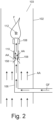
- FIG. 2 is a schematic diagram of chimney tube 102, burner 108, and fuel line 106 of system 100 from FIG. 1 .
- fuel line 106 inside of chimney tube 102 includes shutter 110 and entrainment holes 158.
- Entrainment holes 158 are formed in fuel line 106 and fluidically connect an interior passage of fuel line 106 with the flow of air and aerosolized agent AA in chimney tube 102.
- Shutter 110 is on fuel line 106 and can move and adjust position on fuel line 106 to cover and close entrainment holes 158, to partially cover entrainment holes 158, and to fully uncover and open entrainment holes 158.
- FIG. 1 fuel line 106 inside of chimney tube 102 includes shutter 110 and entrainment holes 158.
- Entrainment holes 158 are formed in fuel line 106 and fluidically connect an interior passage of fuel line 106 with the flow of air and aerosolized agent AA in chimney tube 102.
- Shutter 110 is on fuel line 106 and can move and adjust position on fuel line 106
- shutter 110 is a sleeve that slides on fuel line 106 and has a length sufficient to cover entrainment holes 158 when shutter 110 is slid over entrainment holes 158.
- shutter 110 can be connected to fuel line 106 by a threaded connection between shutter 110 and fuel line 106 such that shutter 110 can be twisted up or down on fuel line 106 to cover or partially cover entrainment holes 158.
- gas fuel GF flows through fuel line 106 to burner 108 for ignition and combustion to produce flame F. While gas fuel GF flows through fuel line 106 to burner 108, a portion of aerosolized agent AA and the air flowing in chimney tube 102 flows through entrainment holes 158 into fuel line 106 to mix with gas fuel GF and flow to burner 108. Allowing aerosolized agent AA and air to mix with gas fuel GF before gas fuel GF is combusted at burner 108 helps to evaluate the efficacy of aerosolize agent AA at inerting gas fuel GF.
- the amount of aerosolized agent AA and air flowing into fuel line 106 through entrainment holes 158 can be controlled and adjusted by shutter 110, thereby allowing a technician to tune and test different mixtures and concentrations of aerosolized agent AA and air in gas fuel GF.
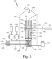
- FIG. 3 is a schematic diagram of another example of system 100 for testing and evaluating an inerting concentration of aerosolized agent AA.
- System 100 shown in FIG. 3 is similar to the example of system 100 in FIG. 1 except fuel line 106 of system 100 in FIG. 3 does not include entrainment holes 158 and shutter 110.
- System 100 in FIG. 3 includes air source 160 and air flow meter 162 located outside cabinet 134. Air flow meter 162 fluidically connects air source 160 to fuel line 106. Air flow meter 162 controls and meters air from air source 160 that is mixed into the gas fuel inside of fuel line 106.
- Air flow meter 162 controls and meters air from air source 160 that is mixed into the gas fuel inside of fuel line 106.
- the flame at burner 108 receives oxygen from the air and gas fuel mixture in fuel line 106 and is not completely dependent on oxygen present in the mixed air and aerosolized agent AA flowing through chimney tube 102.
- the stoichiometry fuel/air ratio
- the flame of burner 108 receives oxygen from fuel line 106
- the flame of system 100 of FIG. 3 can be more difficult for aerosolized agent AA to extinguish than the flame of system 100.
- system 100 of FIG. 3 can be used to simulate scenarios where the inerting concentration of aerosolized agent AA needs to be more robust.
- a system for evaluating inerting concentration of fire suppression agents.
- the system includes a mixing manifold with a mixing chamber, an air flow inlet fluidically connected to the mixing chamber, a fire suppression agent inlet fluidically connected to the mixing chamber, and a manifold outlet fluidically connected to the mixing chamber.
- the system also includes a chimney tube extending vertically from the manifold outlet to a chimney outlet, and a burner inside the chimney tube between the manifold outlet and the chimney outlet.
- An ignitor is inside the chimney tube between the burner and the chimney outlet.
- a fuel line extends into the chimney tube and is connected to the burner.
- the system of the preceding paragraph can optionally include, additionally and/or alternatively, any one or more of the following features, configurations and/or additional components:
- the fuel line extends vertically upward toward the burner inside the chimney tube, and wherein the fuel line comprises: entrainment holes formed in the fuel line, wherein the entrainment holes fluidically connect an interior passage of the fuel line with the chimney tube; and a shutter on the fuel line, wherein the shutter is configured to move on the fuel line to open and/or at least partially cover and close the entrainment holes;
- a method for evaluating inerting concentration of a fire suppression agent.
- the method includes flowing air vertically upward relative to gravity into a chimney tube at a velocity that exceeds a settling velocity of the fire suppression agent.
- Fuel flows into the flowing air in the chimney tube via a burner in the chimney tube.
- a targeted concentration of the fire suppression agent is introduced into the flowing air and into the flowing fuel.
- An ignitor is activated to provide ignition energy to the flowing air and the flowing fuel.
- the ignitor is then deactivated.
- the targeted concentration of the fire suppression agent is determined to be below the inerting concentration of the fire suppression agent if combustion of the flowing fuel persists beyond three seconds after the ignitor is deactivated.
- the targeted concentration of the fire suppression agent is determined to be above the inerting concentration of the fire suppression agent if the combustion of the flowing fuel does not persist beyond three seconds after the ignitor is deactivated.
- the method of the preceding paragraph can optionally include, additionally and/or alternatively, any one or more of the following features, configurations and/or additional components:
- a method for evaluating inerting concentration of a fire suppression agent.
- the method includes flowing air vertically upward relative to gravity into a chimney tube and flowing fuel into the flowing air in the chimney tube.
- a targeted concentration of the fire suppression agent is introduced into the flowing air and into the flowing fuel in the chimney tube.
- An ignitor in the chimney tube is ignited to provide ignition energy to the flowing air and the flowing fuel, and the ignitor is deactivated.
- the targeted concentration of the fire suppression agent is determined to be below the inerting concentration of the fire suppression agent if combustion of the flowing fuel occurs and persists beyond three seconds after the ignitor is deactivated.
- the targeted concentration of the fire suppression agent is determined to be at or above the inerting concentration of the fire suppression agent if combustion of the flowing fuel does not persist beyond three seconds after the ignitor is deactivated.
- the method of the preceding paragraph can optionally include, additionally and/or alternatively, any one or more of the following features, configurations and/or additional components: measuring the targeted concentration of the fire suppression agent in the flowing air in the chimney tube by measuring, by a light sensor, a light transmission passing through the fire suppression agent and the chimney tube from a light source and correlating the light transmission with a certain concentration level of the fire suppression agent.
Landscapes
- Engineering & Computer Science (AREA)
- Health & Medical Sciences (AREA)
- Public Health (AREA)
- Business, Economics & Management (AREA)
- Emergency Management (AREA)
- Chemical & Material Sciences (AREA)
- Combustion & Propulsion (AREA)
- Mechanical Engineering (AREA)
- General Engineering & Computer Science (AREA)
- Investigating, Analyzing Materials By Fluorescence Or Luminescence (AREA)
Abstract
Description
- This disclosure is directed to fire suppression agents, and in particular, to testing fire suppression agents.
- The aviation industry is moving away from Halon 1301 and other conventional gaseous fire suppression agents due to global warming and ozone related environmental concerns. The replacements to these industry standard agents must demonstrate equivalent fire suppression performance. One common metric used to quantify the performance of a fire suppression agent is inerting concentration. The inerting concentration of a fire suppression agent is the concentration at which the fire suppression agent extinguishes a flame. Many alternative agents involve aerosolized liquids and/or dry powders. Quantifying the inerting concentration of these aerosolized agents is challenging because the standard inerting test method requires quiescent conditions (no airflow) of the fire suppression agent being tested. In these quiescent conditions of the standard inerting test, aerosolized liquids and dry powders settle out of the air because of gravitational effects. Thus, evaluating the inerting concentration of an aerosolized agent is impossible in quiescent conditions.
- A system is disclosed for evaluating inerting concentration of fire suppression agents. The system includes a mixing manifold with a mixing chamber, an air flow inlet fluidically connected to the mixing chamber, a fire suppression agent inlet fluidically connected to the mixing chamber, and a manifold outlet fluidically connected to the mixing chamber. The system also includes a chimney tube extending vertically from the manifold outlet to a chimney outlet, and a burner inside the chimney tube between the manifold outlet and the chimney outlet. An ignitor is inside the chimney tube between the burner and the chimney outlet. A fuel line extends into the chimney tube and is connected to the burner.
- A method is disclosed for evaluating inerting concentration of a fire suppression agent. The method includes flowing air vertically upward relative to gravity into a chimney tube at a velocity that exceeds a settling velocity of the fire suppression agent. Fuel flows into the flowing air in the chimney tube via a burner in the chimney tube. A targeted concentration of the fire suppression agent is introduced into the flowing air and into the flowing fuel. An ignitor is activated to provide ignition energy to the flowing air and the flowing fuel. The ignitor is then deactivated. The targeted concentration of the fire suppression agent is determined to be below the inerting concentration of the fire suppression agent if combustion of the flowing fuel persists beyond three seconds after the ignitor is deactivated. The targeted concentration of the fire suppression agent is determined to be above the inerting concentration of the fire suppression agent if the combustion of the flowing fuel does not persist beyond three seconds after the ignitor is deactivated.
- A method is disclosed for evaluating inerting concentration of a fire suppression agent. The method includes flowing air vertically upward relative to gravity into a chimney tube and flowing fuel into the flowing air in the chimney tube. A targeted concentration of the fire suppression agent is introduced into the flowing air and into the flowing fuel in the chimney tube. An ignitor in the chimney tube is ignited to provide ignition energy to the flowing air and the flowing fuel, and the ignitor is deactivated. The targeted concentration of the fire suppression agent is determined to be below the inerting concentration of the fire suppression agent if combustion of the flowing fuel occurs and persists beyond three seconds after the ignitor is deactivated. The targeted concentration of the fire suppression agent is determined to be at or above the inerting concentration of the fire suppression agent if combustion of the flowing fuel does not persist beyond three seconds after the ignitor is deactivated. The method may further comprise: measuring the targeted concentration of the fire suppression agent in the flowing air in the chimney tube by measuring, by a light sensor, a light transmission passing through the fire suppression agent and the chimney tube from a light source and correlating the light transmission with a certain concentration level of the fire suppression agent.
-
-
FIG. 1 is a schematic diagram of a system for testing and evaluating an inerting concentration of an aerosolized fire suppression agent. -
FIG. 2 is a schematic diagram of a chimney tube, a burner, and a fuel line of the system fromFIG. 1 . -
FIG. 3 is a schematic diagram of another example of the system for testing and evaluating an inerting concentration of an aerosolized fire suppression agent. - While the above-identified drawing figures set forth one or more examples, other examples are also contemplated. It should be understood that numerous other modifications and examples can be devised by those skilled in the art, which fall within the scope and spirit of the principles of the claims. The figures may not be drawn to scale, and applications and examples may include features and components not specifically shown in the drawings.
-
FIG. 1 is a schematic diagram ofsystem 100 for testing and evaluating an inerting concentration of aerosolized agent AA. Aerosolized agent AA is a powder, liquid, and/or gaseous fire suppression agent that is mixed with an air flow to form aerosolized agent AA. As shown inFIG. 1 ,system 100 includeschimney tube 102 withchimney outlet 103,mixing manifold 104,fuel line 106,burner 108,shutter 110,ignitor 112, airmass flow controller 114,air line 116,agent reservoir 118 containingagent 120,feed pipe 122,auger 124,motor 126,gas fuel source 128,fuel flow meter 130,sensors 132, andcabinet 134.Mixing manifold 104 includesagent inlet 136,air flow inlet 138,mixing chamber 139,manifold outlet 140, andscreen 142.Sensors 132 includelaser 144,fiber patch cable 146,collimator 148,laser detector 150,photodiode 152, andthermocouple 154.Cabinet 134 includescabinet outlet 156. - Chimney
tube 102 and mixingmanifold 104 are housed withincabinet 134. In the example ofFIG. 1 , mixingmanifold 104 is positioned underneathchimney tube 102.Chimney tube 102 extends vertically, relative to gravitational ground, frommanifold outlet 140 tochimney outlet 103.Chimney tube 102 is formed from a transparent material, such as fire-safe glass or fire-safe plastic, so that a technician and/or sensors can view an interior ofchimney tube 102 during operation ofsystem 100. In other examples,chimney tube 102 can include windows to allow visual access to the interior ofchimney tube 102 during operation ofsystem 100.Air flow inlet 138 ofmixing manifold 104 is fluidically connected tomixing chamber 139.Agent inlet 136 ofmixing manifold 104 is also fluidically connected tomixing chamber 139. Manifoldoutlet 140 is abovemixing chamber 139 relative to ground and is fluidically connected tomixing chamber 139. Airmass flow controller 114 is fluidically connected toair flow inlet 138 of mixingmanifold 104 byair line 116. Airmass flow controller 114 measures and controls a flow of air enteringair flow inlet 138 andmixing chamber 139. -
Feed pipe 122 connectsagent reservoir 118 toagent inlet 136 of mixingmanifold 104. Auger 124 extends throughagent reservoir 118,feed pipe 122, andagent inlet 136. A rotor ofmotor 126 is connected to an end ofauger 124. During operation ofsystem 100,motor 126 rotatesauger 124 to deliveragent 120 inagent reservoir 118 to mixingchamber 139 in a controlled manner.Agent 120 inagent reservoir 118 can be a powder fire suppression agent or a liquid fire suppression agent. Whenagent 120 inagent reservoir 118 is a liquid fire suppression agent,feed pipe 122 andauger 124 can be angled at an incline fromagent reservoir 118 to mixingchamber 139. Incliningfeed pipe 122 andauger 124 can prevent free-flow ofagent 120 fromagent reservoir 118 to mixingchamber 139. In other examples,agent 120 can be a gaseous fire suppression agent and a hose and gas meter can connectagent reservoir 118 to mixingchamber 139. - When
system 100 is in operation, airmass flow controller 114 directs a flow of air intoair flow inlet 138 ofmixing chamber 139, throughmixing chamber 139, throughmanifold outlet 140, and intochimney tube 102. As the air is flowing through mixingmanifold 104 and intochimney tube 102,motor 126 rotatesauger 124 to move andmeter agent 120 fromagent reservoir 118 throughfeed pipe 122, throughagent inlet 136 ofmixing manifold 104, and intomixing chamber 139. Onceagent 120reaches mixing chamber 139,agent 120 mixes with the flow of air in mixingchamber 139 and aerosolizes to generate aerosolized agent AA. Aerosolized agent AA flows with the flowing air out of mixingchamber 139, throughmanifold outlet 140, and intochimney tube 102. The air flowing in mixingmanifold 104 andchimney tube 102 flows at a velocity exceeding an aerosol settling velocity of aerosolized agent AA to reduce the likelihood ofagent 120 settling out of aerosolized agent AA.Screen 142 is positioned onmanifold outlet 140. As the air and aerosolized agent AA flows throughmanifold outlet 140 and throughscreen 142,screen 142 helps mix and laminarize the flow of air and aerosolized agent AA enteringchimney tube 102. The laminar flow of air and aerosolized agent AA flows vertically up throughchimney tube 102 at a velocity that exceeds the aerosol settling velocity of aerosolized agent AA and exitschimney tube 102 throughchimney outlet 103.Cabinet 134 encloseschimney tube 102 to contain aerosolized agent AA exitingchimney outlet 103. During operation ofsystem 100,cabin outlet 156 ofcabinet 134 can be connected to a sock filter module (not shown) to filter aerosolized agent AA out of the exhaust ofchimney tube 102. -
Burner 108 is insidechimney tube 102 betweenmanifold outlet 140 andchimney outlet 103.Fuel line 106 extends intochimney tube 102 to connect toburner 108 and supply a gas fuel toburner 108. In the example shown inFIG. 1 ,fuel line 106 extends vertically toburner 108 insidechimney tube 102 such thatfuel line 106 is aligned with the laminar flow of the air and the aerosolized agent AA insidechimney tube 102.Ignitor 112 is insidechimney tube 102 aboveburner 108 such thatignitor 112 is vertically betweenburner 108 andchimney outlet 103.Ignitor 112 can include spark electrodes or a wire fuse or a hot surface ignitor or any other device capable of providing sufficient ignition energy to the system to ignite thefuel exiting burner 108.Fuel flow meter 130 fluidically connectsfuel line 106 togas fuel source 128 and controls and meters the amount of the gas fuel enteringfuel line 106 andburner 108. The gas fuel can be any gaseous fuel capable of fueling a flame atburner 108. For example, gaseous fuel can be, but is not limited to, propane, butane, methane, and/or hydrocarbon vapor.Gas fuel source 128 can be a pressurized tank of the gaseous fuel or a utility supply line of the gaseous fuel. During operation ofsystem 100,fuel flow meter 130 directs gas fuel intofuel line 106 fromgas fuel source 128, andfuel line 106 directs the gas fuel toburner 108. As the gas fuel exitsburner 108, the gas fuel mixes with the laminar flow of air and aerosolized agent AA andignitor 112 ignites the fuel to combust the gas fuel and produce a flame onburner 108. -
Sensors 132 includelaser 144,fiber patch cable 146,collimator 148,laser detector 150,photodiode 152, andthermocouple 154. As shown in the example ofFIG. 1 ,collimator 148 is mounted ontochimney tube 102 andlaser detector 150 is mounted tochimney tube 102opposite collimator 148.Fiber patch cable 146 connects an output oflaser 144 tocollimator 148 such thatlaser 144 is a light source that supplies a laser beam LB tocollimator 148.Collimator 148 focuses the laser beam LB and/or aims the laser beam LB throughchimney tube 102 tolaser detector 150.Laser detector 150 is a light sensor that measure light transmission of the laser beam LB. During operation ofsystem 100,laser detector 150 can be used to determine a concentration of aerosolized agent AA flowing throughchimney tube 102 by measuring changes in light transmission of the laser beam LB caused by the flow of aerosolized agent AA passing through the laser beam LB.System 100 is calibrated to correlate certain light transmissions of the laser beam LB with certain concentration levels of aerosolized agent AA in the flowing air inside ofchimney tube 102. -
Photodiode 152 is a light sensor that faces an exterior surface ofchimney tube 102 and is positioned along a height ofchimney tube 102 betweenburner 108 andchimney outlet 103. The flame ofburner 108 serves as a light source forphotodiode 152. During operation ofsystem 100,photodiode 152 faces a flame ofburner 108 and measures light transmission of the flame.Photodiode 152 can also be used to determine the concentration of aerosolized agent AA flowing throughchimney tube 102 by measuring changes in the light transmission of the flame caused by the flow of aerosolized agent AA passing betweenphotodiode 152 and the flame ofburner 108.System 100 is calibrated to correlate certain light transmissions of the flame measured byphotodiode 152 with certain concentration levels of aerosolized agent AA in the flowing air inside ofchimney tube 102.Thermocouple 154 is insidechimney tube 102 and is aboveburner 108 and underchimney outlet 103. During operation ofsystem 100,thermocouple 154 is used to determine a temperature aboveburner 108. -
Sensors 132 can also includeisokinetic sampling probe 153 in addition tophotodiode 152 andlaser detector 150, or in place ofphotodiode 152 andlaser detector 150.Isokinetic probe 153 includes a probe tube that extends intochimney tube 102 to collect a sample of aerosolized agent AA during operation ofsystem 100. The sample of aerosolized agent AA collected byisokinetic probe 153 can be weighed or chemically dissolved to determine the amount of aerosolized agent AA collected byisokinetic probe 153.Isokinetic probe 153 can also measure the flow rate throughchimney tube 102 which can be used, along with the measured amount of aerosolized agent AA, to determine the concentration of aerosolized agent AA inchimney tube 102. In other examples, airmass flow controller 114 can measure the mass of air directed throughchimney tube 102, which can be used with the mass measurements of aerosolized agent AA fromisokinetic probe 153 to determine the concentration of aerosolized agent AA inchimney tube 102. - The concentration of aerosolized agent AA can also be determined using
motor 126,auger 124, and airmass flow controller 114. The mass of aerosolized agent AA introduced into the air flowing inchimney tube 102 can be determined by tracking and measuring a rotational speed ofmotor 126 and feed rate ofagent 120 byauger 124. As previously noted, airmass flow controller 114 can measure the mass and flow rate of the air inchimney tube 102. With the mass and flow rate of the air inchimney tube 102 known and the mass and feed rate ofagent 120 known, the concentration of aerosolized agent AA can be calculated by taking a ratio between the mas of the air flowing throughchimney tube 102 and the mass ofagent 120 aerosolized into aerosolized agent AA. During operation ofsystem 100, any aerosolized agent AA that settles out of the air flow inchimney 120 can be collected, weighed, and discounted from the calculation of the concentration of aerosolized agent AA. - To quantify an inerting concentration of aerosolized agent AA, the following method is utilized. First the flow of air in
chimney tube 102 and the flow of fuel infuel line 106 are established. Then a targeted concentration of aerosolized agent AA is fed intochimney tube 102.Ignitor 112 is then activated to provide sufficient ignition energy and then deactivated. If combustion persists for longer than three seconds afterignitor 112 is deactivated, then the supplied concentration of aerosolized agent AA was below the inerting concentration. If combustion does not persist beyond three seconds afterignitor 112 is deactivated, then the supplied concentration of aerosolized agent AA was above the inerting concentration. The concentration of aerosolized agent AA in the air flowing inchimney tube 102 can be controlled by adjusting the speed ofmotor 126 so thatauger 122 deliversagent 120 into mixingmanifold 104 at faster or slower rates.Laser detector 150 andphotodiode 152 are used as described above to quantify the concentration of aerosolized agent AA during the period of time whenignitor 112 was active. As discussed below with reference toFIG. 2 ,shutter 110 is onfuel line 106 and can be used bysystem 100 to adjust mixing of aerosolized agent AA and the air inchimney tube 102 with the fuel infuel line 106, thus providing control over the air-fuel ratio at theburner 108 and allowing for the inerting concentration of aerosolized agent AA to be evaluated over a range of conditions. -
FIG. 2 is a schematic diagram ofchimney tube 102,burner 108, andfuel line 106 ofsystem 100 fromFIG. 1 . In the example ofFIG. 2 ,fuel line 106 inside ofchimney tube 102 includesshutter 110 and entrainment holes 158. Entrainment holes 158 are formed infuel line 106 and fluidically connect an interior passage offuel line 106 with the flow of air and aerosolized agent AA inchimney tube 102.Shutter 110 is onfuel line 106 and can move and adjust position onfuel line 106 to cover and close entrainment holes 158, to partially cover entrainment holes 158, and to fully uncover and open entrainment holes 158. In the example ofFIG. 2 ,shutter 110 is a sleeve that slides onfuel line 106 and has a length sufficient to cover entrainment holes 158 whenshutter 110 is slid over entrainment holes 158. In other examples,shutter 110 can be connected tofuel line 106 by a threaded connection betweenshutter 110 andfuel line 106 such thatshutter 110 can be twisted up or down onfuel line 106 to cover or partially cover entrainment holes 158. During operation ofsystem 100, as discussed above with reference toFIG. 1 , the laminar flow of air and aerosolized agent AA flows vertically up throughchimney tube 102 at a velocity that exceeds the aerosol settling velocity of aerosolized agent AA. As the laminar flow of air and aerosolized agent AA flows vertically up throughchimney tube 102, gas fuel GF flows throughfuel line 106 toburner 108 for ignition and combustion to produce flame F. While gas fuel GF flows throughfuel line 106 toburner 108, a portion of aerosolized agent AA and the air flowing inchimney tube 102 flows throughentrainment holes 158 intofuel line 106 to mix with gas fuel GF and flow toburner 108. Allowing aerosolized agent AA and air to mix with gas fuel GF before gas fuel GF is combusted atburner 108 helps to evaluate the efficacy of aerosolize agent AA at inerting gas fuel GF. The amount of aerosolized agent AA and air flowing intofuel line 106 throughentrainment holes 158 can be controlled and adjusted byshutter 110, thereby allowing a technician to tune and test different mixtures and concentrations of aerosolized agent AA and air in gas fuel GF. -
FIG. 3 is a schematic diagram of another example ofsystem 100 for testing and evaluating an inerting concentration of aerosolized agent AA.System 100 shown inFIG. 3 is similar to the example ofsystem 100 inFIG. 1 exceptfuel line 106 ofsystem 100 inFIG. 3 does not includeentrainment holes 158 andshutter 110.System 100 inFIG. 3 includesair source 160 andair flow meter 162 located outsidecabinet 134.Air flow meter 162 fluidically connectsair source 160 tofuel line 106.Air flow meter 162 controls and meters air fromair source 160 that is mixed into the gas fuel inside offuel line 106. During operation ofsystem 100 ofFIG. 3 , the flame atburner 108 receives oxygen from the air and gas fuel mixture infuel line 106 and is not completely dependent on oxygen present in the mixed air and aerosolized agent AA flowing throughchimney tube 102. By adjusting the flow rates of air and fuel the stoichiometry (fuel/air ratio) can be adjusted. Since the flame ofburner 108 receives oxygen fromfuel line 106, the flame ofsystem 100 ofFIG. 3 can be more difficult for aerosolized agent AA to extinguish than the flame ofsystem 100. As the flame ofsystem 100 ofFIG. 3 is more difficult to extinguish than the system ofFIG. 1 ,system 100 ofFIG. 3 can be used to simulate scenarios where the inerting concentration of aerosolized agent AA needs to be more robust. - The following are non-exclusive descriptions of possible embodiments of the present invention.
- In one example, a system is disclosed for evaluating inerting concentration of fire suppression agents. The system includes a mixing manifold with a mixing chamber, an air flow inlet fluidically connected to the mixing chamber, a fire suppression agent inlet fluidically connected to the mixing chamber, and a manifold outlet fluidically connected to the mixing chamber. The system also includes a chimney tube extending vertically from the manifold outlet to a chimney outlet, and a burner inside the chimney tube between the manifold outlet and the chimney outlet. An ignitor is inside the chimney tube between the burner and the chimney outlet. A fuel line extends into the chimney tube and is connected to the burner.
- The system of the preceding paragraph can optionally include, additionally and/or alternatively, any one or more of the following features, configurations and/or additional components:
- the fuel line extends vertically upward toward the burner inside the chimney tube, and wherein the fuel line comprises: entrainment holes formed in the fuel line, wherein the entrainment holes fluidically connect an interior passage of the fuel line with the chimney tube; and a shutter on the fuel line, wherein the shutter is configured to move on the fuel line to open and/or at least partially cover and close the entrainment holes;
- the shutter is a sleeve that slides on the fuel line;
- the shutter is connected to the fuel line by a threaded connection between the shutter and the fuel line;
- a fuel flow meter fluidically connecting the fuel line to a gas fuel source;
- an air mass flow controller fluidically connected the air flow inlet of the mixing manifold;
- an agent reservoir connected to the fire suppression agent inlet of the mixing manifold; an auger extending through the agent reservoir and the fire suppression agent inlet; and a motor connected to the auger;
- a screen on the manifold outlet;
- the system further comprising: a laser; a laser detector mounted to the chimney tube; a collimator mounted onto the chimney tube opposite the laser detector and configured to focus a laser beam from the laser and/or aim the laser beam across the chimney tube to the laser detector; and/or
- a thermocouple inside the chimney tube between the burner and the chimney outlet; and/or a photodiode facing the burner and the ignitor; and/or an isokinetic probe comprising a probe tube extending into the chimney tube.
- In another example, a method is disclosed for evaluating inerting concentration of a fire suppression agent. The method includes flowing air vertically upward relative to gravity into a chimney tube at a velocity that exceeds a settling velocity of the fire suppression agent. Fuel flows into the flowing air in the chimney tube via a burner in the chimney tube. A targeted concentration of the fire suppression agent is introduced into the flowing air and into the flowing fuel. An ignitor is activated to provide ignition energy to the flowing air and the flowing fuel. The ignitor is then deactivated. The targeted concentration of the fire suppression agent is determined to be below the inerting concentration of the fire suppression agent if combustion of the flowing fuel persists beyond three seconds after the ignitor is deactivated. The targeted concentration of the fire suppression agent is determined to be above the inerting concentration of the fire suppression agent if the combustion of the flowing fuel does not persist beyond three seconds after the ignitor is deactivated.
- The method of the preceding paragraph can optionally include, additionally and/or alternatively, any one or more of the following features, configurations and/or additional components:
- directing a portion of the fire suppression agent and the air flowing in the chimney tube through entrainment holes in a fuel line of the burner to mix with the flowing fuel in the fuel line;
- controlling a flow of the portion of the fire suppression agent and the air passing through the entrainment holes with a shutter on the fuel line;
- quantifying the targeted concentration of the fire suppression agent in the flowing air in the chimney tube by: aiming a collimated laser beam from a laser through the chimney tube to a laser detector positioned on an opposite side of the chimney tube from the laser; and measuring, by the laser detector, a light transmission of the collimated laser beam;
- quantifying the targeted concentration of the fire suppression agent in the flowing air in the chimney tube by measuring a light transmission of a flame of the burner with a photodiode;
- quantifying the targeted concentration of the fire suppression agent in the flowing air in the chimney tube by: collecting a sample of the fire suppression agent in the flowing air in the chimney tube with an isokinetic probe; measuring a mass of the sample; measuring a mass of the flowing air in the chimney tube with the isokinetic probe and/or an air mass flow controller; and calculating a ratio between the mass of the sample with the mass of the flowing air in the chimney tube;
- passing the flowing air through a mixing manifold prior to directing the flowing air vertically upward into the chimney tube; and metering a powder, liquid, and/or gaseous fire suppression agent into the mixing manifold to mix the powder, liquid, and/or gaseous fire suppression agent with the flowing air in the mixing manifold to generate the fire suppression agent; and/or
- passing the flowing air and the fire suppression agent through a screen before entering the chimney tube to laminarize the flowing air and the fire suppression agent.
- In another example, a method is disclosed for evaluating inerting concentration of a fire suppression agent. The method includes flowing air vertically upward relative to gravity into a chimney tube and flowing fuel into the flowing air in the chimney tube. A targeted concentration of the fire suppression agent is introduced into the flowing air and into the flowing fuel in the chimney tube. An ignitor in the chimney tube is ignited to provide ignition energy to the flowing air and the flowing fuel, and the ignitor is deactivated. The targeted concentration of the fire suppression agent is determined to be below the inerting concentration of the fire suppression agent if combustion of the flowing fuel occurs and persists beyond three seconds after the ignitor is deactivated. The targeted concentration of the fire suppression agent is determined to be at or above the inerting concentration of the fire suppression agent if combustion of the flowing fuel does not persist beyond three seconds after the ignitor is deactivated.
- The method of the preceding paragraph can optionally include, additionally and/or alternatively, any one or more of the following features, configurations and/or additional components:
measuring the targeted concentration of the fire suppression agent in the flowing air in the chimney tube by measuring, by a light sensor, a light transmission passing through the fire suppression agent and the chimney tube from a light source and correlating the light transmission with a certain concentration level of the fire suppression agent. - While the invention has been described with reference to an exemplary embodiment(s), it will be understood by those skilled in the art that various changes may be made and equivalents may be substituted for elements thereof without departing from the scope of the invention. In addition, many modifications may be made to adapt a particular situation or material to the teachings of the invention without departing from the essential scope thereof. Therefore, it is intended that the invention not be limited to the particular embodiment(s) disclosed, but that the invention will include all embodiments falling within the scope of the appended claims.
Claims (15)
- A system for evaluating inerting concentration of fire suppression agents comprising:a mixing manifold comprising a mixing chamber, an air flow inlet fluidically connected to the mixing chamber, a fire suppression agent inlet fluidically connected to the mixing chamber, and a manifold outlet fluidically connected to the mixing chamber;a chimney tube extending vertically from the manifold outlet to a chimney outlet;a burner inside the chimney tube between the manifold outlet and the chimney outlet;an ignitor inside the chimney tube between the burner and the chimney outlet; anda fuel line extending into the chimney tube and connected to the burner.
- The system of claim 1, wherein the fuel line extends vertically upward toward the burner inside the chimney tube, and wherein the fuel line comprises:entrainment holes formed in the fuel line, wherein the entrainment holes fluidically connect an interior passage of the fuel line with the chimney tube; anda shutter on the fuel line, wherein the shutter is configured to move on the fuel line to open and/or at least partially cover and close the entrainment holes.
- The system of claim 2, wherein the shutter is a sleeve that slides on the fuel line.
- The system of claim 2, wherein the shutter is connected to the fuel line by a threaded connection between the shutter and the fuel line.
- The system of any preceding claim, further comprising:a fuel flow meter fluidically connecting the fuel line to a gas fuel source; and/oran air mass flow controller fluidically connected to the air flow inlet of the mixing manifold.
- The system of any preceding claim, further comprising:an agent reservoir connected to the fire suppression agent inlet of the mixing manifold;an auger extending through the agent reservoir and the fire suppression agent inlet; anda motor connected to the auger.
- The system of any preceding claim, further comprising:
a screen on the manifold outlet. - The system of any preceding claim, further comprising:a laser;a laser detector mounted to the chimney tube;a collimator mounted onto the chimney tube opposite the laser detector and configured to focus a laser beam from the laser and/or aim the laser beam across the chimney tube to the laser detector.
- The system of any preceding claim, further comprising:a thermocouple inside the chimney tube between the burner and the chimney outlet; and/ora photodiode facing the burner and the ignitor; and/oran isokinetic probe comprising a probe tube extending into the chimney tube.
- A method for evaluating inerting concentration of a fire suppression agent, wherein the method comprises:flowing air vertically upward relative to gravity into a chimney tube at a velocity that exceeds a settling velocity of the fire suppression agent;flowing fuel into the flowing air in the chimney tube via a burner in the chimney tube;introducing a targeted concentration of the fire suppression agent into the flowing air and into the flowing fuel;activating an ignitor to provide ignition energy to the flowing air and the flowing fuel;deactivating the ignitor;determining the targeted concentration of the fire suppression agent is below the inerting concentration of the fire suppression agent if combustion of the flowing fuel persists beyond three seconds after the ignitor is deactivated; anddetermining the targeted concentration of the fire suppression agent is above the inerting concentration of the fire suppression agent if the combustion of the flowing fuel does not persist beyond three seconds after the ignitor is deactivated.
- The method of claim 10, further comprising:
directing a portion of the fire suppression agent and the air flowing in the chimney tube through entrainment holes in a fuel line of the burner to mix with the flowing fuel in the fuel line; and, optionally, controlling a flow of the portion of the fire suppression agent and the air passing through the entrainment holes with a shutter on the fuel line.. - The method of claim 10 or 11, further comprising:
quantifying the targeted concentration of the fire suppression agent in the flowing air in the chimney tube by:aiming a collimated laser beam from a laser through the chimney tube to a laser detector positioned on an opposite side of the chimney tube from the laser; andmeasuring, by the laser detector, a light transmission of the collimated laser beam. - The method of claim 10, 11, or 12, further comprising:
quantifying the targeted concentration of the fire suppression agent in the flowing air in the chimney tube by measuring a light transmission of a flame of the burner with a photodiode. - The method of any one of claims 10-13, further comprising:
quantifying the targeted concentration of the fire suppression agent in the flowing air in the chimney tube by:collecting a sample of the fire suppression agent in the flowing air in the chimney tube with an isokinetic probe;measuring a mass of the sample;measuring a mass of the flowing air in the chimney tube with the isokinetic probe and/or an air mass flow controller; andcalculating a ratio between the mass of the sample with the mass of the flowing air in the chimney tube. - The method of any one of claims 10-15, further comprising:passing the flowing air through a mixing manifold prior to directing the flowing air vertically upward into the chimney tube; andmetering a powder, liquid, and/or gaseous fire suppression agent into the mixing manifold to mix the powder, liquid, and/or gaseous fire suppression agent with the flowing air in the mixing manifold to generate the fire suppression agent; and wherein the method, optionally, further comprises passing the flowing air and the fire suppression agent through a screen before entering the chimney tube to laminarize the flowing air and the fire suppression agent.
Applications Claiming Priority (2)
| Application Number | Priority Date | Filing Date | Title |
|---|---|---|---|
| US202363496814P | 2023-04-18 | 2023-04-18 | |
| US18/456,601 US12649077B2 (en) | 2023-04-18 | 2023-08-28 | Method of evaluating the inerting concentration of an aerosol fire suppression agent |
Publications (2)
| Publication Number | Publication Date |
|---|---|
| EP4450873A1 true EP4450873A1 (en) | 2024-10-23 |
| EP4450873B1 EP4450873B1 (en) | 2026-06-03 |
Family
ID=90721335
Family Applications (1)
| Application Number | Title | Priority Date | Filing Date |
|---|---|---|---|
| EP24169738.2A Active EP4450873B1 (en) | 2023-04-18 | 2024-04-11 | Method of evaluating the inerting concentration of an aerosol fire suppression agent |
Country Status (2)
| Country | Link |
|---|---|
| US (1) | US12649077B2 (en) |
| EP (1) | EP4450873B1 (en) |
Citations (4)
| Publication number | Priority date | Publication date | Assignee | Title |
|---|---|---|---|---|
| CN103454387A (en) * | 2013-09-24 | 2013-12-18 | 中国科学技术大学 | Cup type combustor for foam extinguishing agent experiment |
| CN203376300U (en) * | 2013-07-23 | 2014-01-01 | 公安部天津消防研究所 | Fire extinguishing performance test device for ultrafine powder fire extinguishing agent |
| CN211292579U (en) * | 2019-09-02 | 2020-08-18 | 应急管理部天津消防研究所 | An on-line testing device for gas components generated during the fire extinguishing process of a gas fire extinguishing agent |
| CN112345688A (en) * | 2020-11-17 | 2021-02-09 | 中国科学技术大学 | Device and method for testing fire extinguishing efficiency of superfine dry powder extinguishing agent |
-
2023
- 2023-08-28 US US18/456,601 patent/US12649077B2/en active Active
-
2024
- 2024-04-11 EP EP24169738.2A patent/EP4450873B1/en active Active
Patent Citations (4)
| Publication number | Priority date | Publication date | Assignee | Title |
|---|---|---|---|---|
| CN203376300U (en) * | 2013-07-23 | 2014-01-01 | 公安部天津消防研究所 | Fire extinguishing performance test device for ultrafine powder fire extinguishing agent |
| CN103454387A (en) * | 2013-09-24 | 2013-12-18 | 中国科学技术大学 | Cup type combustor for foam extinguishing agent experiment |
| CN211292579U (en) * | 2019-09-02 | 2020-08-18 | 应急管理部天津消防研究所 | An on-line testing device for gas components generated during the fire extinguishing process of a gas fire extinguishing agent |
| CN112345688A (en) * | 2020-11-17 | 2021-02-09 | 中国科学技术大学 | Device and method for testing fire extinguishing efficiency of superfine dry powder extinguishing agent |
Also Published As
| Publication number | Publication date |
|---|---|
| EP4450873B1 (en) | 2026-06-03 |
| US12649077B2 (en) | 2026-06-09 |
| US20240350849A1 (en) | 2024-10-24 |
Similar Documents
| Publication | Publication Date | Title |
|---|---|---|
| US6694796B2 (en) | Device and method for introducing a known dust concentration spike for calibrating particulate matter continuous emission monitoring systems | |
| RU2403393C2 (en) | Testing device of instruments and elements of systems of air-and-gas and dust control of well atmosphere | |
| US8656769B2 (en) | Wind tunnel for studying vaporization of liquids | |
| DE102014101974A1 (en) | Method and apparatus for rapidly detecting the Wobbe index of fuel | |
| US4396299A (en) | Method and apparatus for determining total energy flow in a gas line | |
| CA2771507A1 (en) | Individual burner monitor and control in a furnace | |
| MIZUTANI et al. | Turbulent flame velocities in premixed sprays part i. experimental study | |
| MX2008008432A (en) | Controlled humidification calibration checking of continuous emissions monitoring system. | |
| CN112345688B (en) | A device and method for testing the fire extinguishing efficiency of ultrafine dry powder fire extinguishing agent | |
| Arends et al. | Comparison of techniques for measurements of fog liquid water content | |
| US6327889B1 (en) | Device and method for introducing surrogates, particularly metal surrogates, into an exhaust stream, for simulating an exhaust stream, and for establishing a standardized source | |
| US20240350849A1 (en) | Method of evaluating the inerting concentration of an aerosol fire suppression agent | |
| US20140287518A1 (en) | Method of concentration determination and gas concentration sensor | |
| EP0060681B1 (en) | A combustible gas analyzer | |
| FR2811411A1 (en) | Gas burner for cooking appliance includes detector sensing properties of gas fuel and adjusting fuel mixture accordingly to achieve power output | |
| Brohez et al. | Fire calorimetry relying on the use of the fire propagation apparatus. Part I: early learning from use in Europe | |
| KR102797218B1 (en) | A burner device for calibration and a combustion test device equipped with it | |
| EP2851673A1 (en) | A soot generating device | |
| US5423609A (en) | Method and apparatus for determining the heat of combustion of a material based on the height of a diffusional flame within which the material is burned | |
| McElhoe et al. | Remote measurement of sulfur dioxide emissions using an ultraviolet light sensitive video system | |
| JP2008505836A (en) | Soot generator | |
| CN208125655U (en) | A kind of open fire dust cloud that ignites fires experimental determination device | |
| CN107643363A (en) | A kind of device and method for being used to determine gas extinguishing agent flame-extinguishing concentration | |
| CN116482291A (en) | A fire extinguishing agent fire site safety test device and test method | |
| US6914673B2 (en) | Safety apparatus for an atomic absorption spectrometer burner |
Legal Events
| Date | Code | Title | Description |
|---|---|---|---|
| PUAI | Public reference made under article 153(3) epc to a published international application that has entered the european phase |
Free format text: ORIGINAL CODE: 0009012 |
|
| STAA | Information on the status of an ep patent application or granted ep patent |
Free format text: STATUS: THE APPLICATION HAS BEEN PUBLISHED |
|
| AK | Designated contracting states |
Kind code of ref document: A1 Designated state(s): AL AT BE BG CH CY CZ DE DK EE ES FI FR GB GR HR HU IE IS IT LI LT LU LV MC ME MK MT NL NO PL PT RO RS SE SI SK SM TR |
|
| STAA | Information on the status of an ep patent application or granted ep patent |
Free format text: STATUS: REQUEST FOR EXAMINATION WAS MADE |
|
| 17P | Request for examination filed |
Effective date: 20250415 |
|
| GRAP | Despatch of communication of intention to grant a patent |
Free format text: ORIGINAL CODE: EPIDOSNIGR1 |
|
| STAA | Information on the status of an ep patent application or granted ep patent |
Free format text: STATUS: GRANT OF PATENT IS INTENDED |
|
| INTG | Intention to grant announced |
Effective date: 20251218 |
|
| GRAS | Grant fee paid |
Free format text: ORIGINAL CODE: EPIDOSNIGR3 |
|
| GRAA | (expected) grant |
Free format text: ORIGINAL CODE: 0009210 |
|
| STAA | Information on the status of an ep patent application or granted ep patent |
Free format text: STATUS: THE PATENT HAS BEEN GRANTED |
|
| AK | Designated contracting states |
Kind code of ref document: B1 Designated state(s): AL AT BE BG CH CY CZ DE DK EE ES FI FR GB GR HR HU IE IS IT LI LT LU LV MC ME MK MT NL NO PL PT RO RS SE SI SK SM TR |
|
| REG | Reference to a national code |
Ref country code: CH Ref legal event code: F10 Free format text: ST27 STATUS EVENT CODE: U-0-0-F10-F00 (AS PROVIDED BY THE NATIONAL OFFICE) Effective date: 20260603 Ref country code: GB Ref legal event code: FG4D |
|
| REG | Reference to a national code |
Ref country code: DE Ref legal event code: R096 Ref document number: 602024005188 Country of ref document: DE |
|
| REG | Reference to a national code |
Ref country code: IE Ref legal event code: FG4D |