EP4450851A1 - Stop valve - Google Patents
Stop valve Download PDFInfo
- Publication number
- EP4450851A1 EP4450851A1 EP22906702.0A EP22906702A EP4450851A1 EP 4450851 A1 EP4450851 A1 EP 4450851A1 EP 22906702 A EP22906702 A EP 22906702A EP 4450851 A1 EP4450851 A1 EP 4450851A1
- Authority
- EP
- European Patent Office
- Prior art keywords
- segment
- valve
- sleeve
- base
- opening
- Prior art date
- Legal status (The legal status is an assumption and is not a legal conclusion. Google has not performed a legal analysis and makes no representation as to the accuracy of the status listed.)
- Pending
Links
Images









Classifications
-
- F—MECHANICAL ENGINEERING; LIGHTING; HEATING; WEAPONS; BLASTING
- F16—ENGINEERING ELEMENTS AND UNITS; GENERAL MEASURES FOR PRODUCING AND MAINTAINING EFFECTIVE FUNCTIONING OF MACHINES OR INSTALLATIONS; THERMAL INSULATION IN GENERAL
- F16K—VALVES; TAPS; COCKS; ACTUATING-FLOATS; DEVICES FOR VENTING OR AERATING
- F16K1/00—Lift valves or globe valves, i.e. cut-off apparatus with closure members having at least a component of their opening and closing motion perpendicular to the closing faces
- F16K1/02—Lift valves or globe valves, i.e. cut-off apparatus with closure members having at least a component of their opening and closing motion perpendicular to the closing faces with screw-spindle
- F16K1/04—Lift valves or globe valves, i.e. cut-off apparatus with closure members having at least a component of their opening and closing motion perpendicular to the closing faces with screw-spindle with a cut-off member rigid with the spindle, e.g. main valves
-
- F—MECHANICAL ENGINEERING; LIGHTING; HEATING; WEAPONS; BLASTING
- F16—ENGINEERING ELEMENTS AND UNITS; GENERAL MEASURES FOR PRODUCING AND MAINTAINING EFFECTIVE FUNCTIONING OF MACHINES OR INSTALLATIONS; THERMAL INSULATION IN GENERAL
- F16K—VALVES; TAPS; COCKS; ACTUATING-FLOATS; DEVICES FOR VENTING OR AERATING
- F16K1/00—Lift valves or globe valves, i.e. cut-off apparatus with closure members having at least a component of their opening and closing motion perpendicular to the closing faces
- F16K1/02—Lift valves or globe valves, i.e. cut-off apparatus with closure members having at least a component of their opening and closing motion perpendicular to the closing faces with screw-spindle
-
- F—MECHANICAL ENGINEERING; LIGHTING; HEATING; WEAPONS; BLASTING
- F16—ENGINEERING ELEMENTS AND UNITS; GENERAL MEASURES FOR PRODUCING AND MAINTAINING EFFECTIVE FUNCTIONING OF MACHINES OR INSTALLATIONS; THERMAL INSULATION IN GENERAL
- F16K—VALVES; TAPS; COCKS; ACTUATING-FLOATS; DEVICES FOR VENTING OR AERATING
- F16K1/00—Lift valves or globe valves, i.e. cut-off apparatus with closure members having at least a component of their opening and closing motion perpendicular to the closing faces
- F16K1/32—Details
- F16K1/34—Cutting-off parts, e.g. valve members, seats
- F16K1/42—Valve seats
-
- F—MECHANICAL ENGINEERING; LIGHTING; HEATING; WEAPONS; BLASTING
- F16—ENGINEERING ELEMENTS AND UNITS; GENERAL MEASURES FOR PRODUCING AND MAINTAINING EFFECTIVE FUNCTIONING OF MACHINES OR INSTALLATIONS; THERMAL INSULATION IN GENERAL
- F16K—VALVES; TAPS; COCKS; ACTUATING-FLOATS; DEVICES FOR VENTING OR AERATING
- F16K1/00—Lift valves or globe valves, i.e. cut-off apparatus with closure members having at least a component of their opening and closing motion perpendicular to the closing faces
- F16K1/32—Details
- F16K1/34—Cutting-off parts, e.g. valve members, seats
- F16K1/46—Attachment of sealing rings
-
- F—MECHANICAL ENGINEERING; LIGHTING; HEATING; WEAPONS; BLASTING
- F16—ENGINEERING ELEMENTS AND UNITS; GENERAL MEASURES FOR PRODUCING AND MAINTAINING EFFECTIVE FUNCTIONING OF MACHINES OR INSTALLATIONS; THERMAL INSULATION IN GENERAL
- F16K—VALVES; TAPS; COCKS; ACTUATING-FLOATS; DEVICES FOR VENTING OR AERATING
- F16K27/00—Construction of housing; Use of materials therefor
- F16K27/02—Construction of housing; Use of materials therefor of lift valves
-
- F—MECHANICAL ENGINEERING; LIGHTING; HEATING; WEAPONS; BLASTING
- F16—ENGINEERING ELEMENTS AND UNITS; GENERAL MEASURES FOR PRODUCING AND MAINTAINING EFFECTIVE FUNCTIONING OF MACHINES OR INSTALLATIONS; THERMAL INSULATION IN GENERAL
- F16K—VALVES; TAPS; COCKS; ACTUATING-FLOATS; DEVICES FOR VENTING OR AERATING
- F16K39/00—Devices for relieving the pressure on the sealing faces
- F16K39/02—Devices for relieving the pressure on the sealing faces for lift valves
Definitions
- the present application relates to a field of refrigeration technology, and in particular, to a stop valve.
- a stop valve plays an important role in cutting off and throttling a medium in a pipeline where the stop valve is located in.
- An opening and closing components of the stop valve is a valve core, and the valve core is mainly used for cutting off the medium in low-temperature environments.
- the valve seat includes a base and a sleeve, the base is integrally processed and made of cropper, and there is a problem of stress concentration on a transition portion between the sleeve and the base and being prone to crack.
- a stop valve is provided as follows.
- the stop valve includes a valve seat and a valve core made of stainless steel.
- the valve seat is at least provided with a first opening and a second opening. At least part of the valve core is disposed in the valve seat and capable of moving along an axis of the valve seat to communicate the first opening with the second opening or cut off a communication between the first opening and the second opening.
- the valve seat includes a base and a sleeve, at least part of the valve core is located in the sleeve and extends into the base, and the base and the sleeve are separately arranged and fixedly connected.
- a component when a component is considered “set on” another component, it can be directly set on another component or there may be a centered component present simultaneously.
- a component when a component is considered “disposed on” another component, it can be directly fixed to another component or there may be a centered component present simultaneously.
- a component when a component is considered “fixed to” another component, it can be directly fixed to another component or there may be a centered component present simultaneously.
- the present application provides a stop valve 100.
- the stop valve 100 is installed in a refrigeration system and capable of communicating pipelines and cutting off a communication of the pipelines.
- the stop valve 100 includes a valve body 70 and a valve core 20. At least part of the valve core 20 is disposed in and capable of moving in the valve body 70.
- the valve body 70 includes a valve seat 10.
- the valve body 70 and the valve core 20 are both made of stainless steel, which can reduce a cost.
- the valve body 70 includes the valve seat 10.
- the valve seat 10 is in a hollow structure, which is configured to accommodate components such as the valve core 20 and so on. At least part of the valve core 20 is disposed in the valve seat 10 and capable of moving along an axis of the valve seat 10.
- the valve core 20 can be made of stainless steel. In other embodiments, the valve core 20 can be made of copper.
- the valve seat 10 is provided with a first opening 11 and a second opening 12.
- a first communication pipe 111 is provided in the first opening 11.
- a second communication pipe 121 is provided in the second opening 12.
- the first communication pipe 111 is defined as an inlet of a medium
- the second communication pipe 121 is defined as an outlet of the medium.
- the second communication pipe 121 is defined as an inlet of the medium.
- the medium enters to the stop valve 100 from the first communication pipe 111, and enters into the valve seat 10 through the first opening 11. If the stop valve 100 is opened, the medium passes through the second opening 12 and flows out of the stop valve 100 through the second communication pipe 121.
- the medium can enter into the valve seat 10 through the second opening from the second communication pipe 121, and flow out of the stop valve 100 through the first opening 11 and the first communication pipe 111.
- An end of the first communication pipe 111 away from the valve body 70 is provided with a first connection pipe 112, the first communication pipe 111 and the first connection pipe 112 are separately arranged and fixedly connected, and the first connection pipe 112 is configured to be connected to an external pipeline.
- the first communication pipe 111 and the first connection pipe 112 are capable of being formed by dimensionally formed pipe fittings, respectively, which can save a material.
- the first connection pipe 112 is made of copper.
- the first communication pipe 111 is made of stainless steel, and the first connection pipe 112 is fixed with the first communication pipe 111 by welding. Since air condition pipelines are made of copper, the first connection pipe 112 made of copper is conducive to being connected to the air condition pipelines by welding.
- the first connection pipe 112 is sleeved on an outer wall of an end of the first communication pipe 111, and an inner size of the first connection pipe 112 is greater than that of the first communication pipe 111.
- a contact area between the first connection pipe 112 and the first communication pipe 111 increases, and a welding strength increases; on the other hand, when the stop valve 100 is connected to the external pipeline, an end of the external pipeline is inserted into the first connection pipe 112, which is capable of enabling an inner size of the first communication pipe 111 to be consistent with that of the external pipeline.
- An end of the second communication pipe 121 away from the valve body 70 is provided with a second connection pipe 122.
- the second communication pipe 121 and the second connection pipe 122 are separately arranged and fixedly connected, and the second connection pipe 122 is configured to be connected to the external pipeline.
- the second communication pipe 121 and the second connection pipe 122 are formed by the dimensionally formed pipe fittings, respectively, saving the material and reducing cost.
- the second connection pipe 122 is made of copper, the second communication pipe 121 is made of stainless steel, and the second connection pipe 122 is fixed with the second communication pipe 121 by welding. Since the air condition pipelines are made of copper, the second connection pipe 122 made of copper is conducive to being connected to the air condition pipelines by welding.
- the second connection pipe 122 is sleeved on an outer wall of an end of the second communication pipe 121, and an inner size of the second connection pipe 122 is greater than that of the second communication pipe 121.
- the first communication pipe 111 and the first connection pipe 112 are separately arranged, the first communication pipe 111 and the first connection pipe 112 are capable of being formed by the dimensionally formed pipe fittings, result in saving a material and reducing a cost.
- the second communication pipe 121 and the second connection pipe 122 are capable of being formed by the dimensionally formed pipe fittings, result in saving a material and reducing a cost.
- an inner wall of the valve seat 10 is provided with a step 17, the step 17 is provided with a valve port 131, the valve port 131 is in communication with and coaxial with the first opening 11.
- the valve port 131 is disposed on the valve seat 10 to reduce welding processes.
- a collar 13 can be separately provided in the valve seat 10, and an end of the collar 13 towards the valve core 20 is formed the valve port 131.
- the valve seat 10 is made of stainless steel.
- the valve seat 10 includes a base 15 and a sleeve 14. At least part of the valve core 20 is located in the sleeve 14 and extends into the base 15.
- the base 15 and the sleeve 14 are separately arranged and fixedly connected.
- the first communication pipe 111 and the second communication pipe 121 are fixed on the base 15 by welding, respectively.
- an inner size of the base 15 can be adjusted as required, thereby realizing a function of a large diameter flow rate.
- the valve seat 10 made of stainless steel can reduce cost.
- the valve seat 10 is segmented, which is conducive to processing.
- the base 15 and the sleeve 14 are capable of being used in stop valves 100 of different structures, versatility is excellent and flexibility is high. Thereby, a problem of stress concentration of a transition portion between the base 15 and the sleeve 14 when the valve seat 10 is integrally made by copper can be prevented and it will not be prone to crack.
- the valve seat 10 is provided with a collar 13, the valve port 131 is formed on the collar 13, and the valve port 131 is in communication with the first opening 11. In some embodiments, the valve port 131 is in communication with and coaxial with the first opening 11. When the valve core 20 abuts against the collar 13, a communication between the first opening 11 and the second opening 12 can be cut off.
- a diameter of an opening of the valve seat 10 towards the collar 13 is greater than an outer size of the valve core 20, facilitating installing the valve core 20 from such opening.
- the collar 13 is made of stainless steel, and the collar 13 and the valve seat 10 are separately arranged and fixedly connected. Since the stainless steel is relative hard, the collar 13 and the valve seat 10 are separately arranged, which is conducive to processing and reducing cost.
- the valve seat 10 and the collar 13 are capable of being used in stop valves of different structures, facilitating versatility and flexibility.
- the collar 13 and the base 15 are capable of being processed and formed by the pipe fittings, thereby reducing a generation of a waste material.
- An inner wall of an end of the collar 13 towards the first communication pipe 111 is provided with a second limiting portion 132.
- the first communication pipe 111 abuts against the second limiting portion 132 to restrict a length of the first communication pipe 111 inserting into the collar 13.
- the second limiting portion 132 can be a step surface. In other embodiments, the second limiting portion 132 can be a structure such as a protrusion and so on.
- the collar 13 can be fixed on the valve seat 10 by welding, which is capable of improving a firmness of the stop valve 100.
- An inner size of the base 15 is greater than that of the sleeve 14, thereby saving a material of the sleeve 14.
- the base 15 is fixed with the sleeve 14 by welding, thereby improving a firmness of the stop valve 100.
- the base 15 is formed by a cold heading processing.
- the sleeve 14 is formed by stainless steel pipes.
- the stainless steel pipes are ready-made for easy processing. Since the sleeve 14 is directly made of stainless steel pipes, a portion processed by cold heading is correspondingly shortened, a difficulty of the cold heading process is reduced, the valve seat 10 has a small deformation, while alleviating a problem of stress concentration, which is not prone to crack. By such arrangement, it can reduce a generation of a waste material.
- the base 15 includes a main body segment 152 and a first segment 151, and the main body segment 152 is connected to and integrated with the first segment 151.
- the first segment 151 is provided on a surface of an end of the main body segment 152 towards the sleeve 14, the first segment 151 protrudes relative to an end surface of the main body segment 152, the first segment 151 is configured to be connected to the sleeve 14, and a diameter of the circumscribed circle of the first segment 151 is less than that of the main body segment 152, thereby saving a material.
- the first segment 151 is in a ring shape and provided with a first installing opening 1511.
- the main body segment 152 is in a hollow structure.
- the first installing opening is in communication with the main body segment 152.
- the sleeve 14 extends into the first installing opening 1511.
- the base 15 further includes a second segment 153.
- the main body segment 152 is connected to and integrated with the second segment 153.
- the second segment 153 is provided on an end surface of an end of the main body segment 152 away from the first segment 151.
- the second segment 153 protrudes relative to an end surface of the main body segment 152.
- a diameter of a circumscribed circle of the second segment 153 is less than that of a circumscribed circle of the main body segment 152.
- the second segment 153 is configured to fix the base 15 by fitting with other components.
- the main body segment 152 is in a square shape, the first segment 151 is in a ring shape, and the second segment 153 is in a column shape.
- the main body segment 152 can be in a circle shape, the first segment 151 can be in a square ring shape, and the second segment 153 can be in a prismatic shape.
- the valve seat 10 further includes a connection ring 16, the connection ring 16 is sleeve on an outer wall of an end of the sleeve 14, the connection ring 16 is disposed in the first installing opening 1511 and fixedly connected to an inner wall of the first installing opening 1511.
- the connection ring 16 is disposed between the base 15 and the sleeve 14, a side of the connection ring 16 towards the sleeve 14 is fixedly connected to the sleeve 14, a side of the connection ring 16 away from the sleeve 14 is fixedly connected to the base 15, and an outer size of the sleeve 14 is less than that of the base 15.
- connection ring 16 is capable of reducing both a width of the sleeve 14 and a width of the valve core 20, thereby saving a material. Furthermore, a material of a sealing component in the sleeve 14 is saved, thereby saving a material and reducing a process difficulty, as long as the sleeve 14 plays a guiding role in the valve core 20.
- the base 15 is relatively big, which is capable of increasing a flow rate of the medium.
- connection ring 16 can further be sleeved on the first installing opening 1511 and fixedly connected to an outer wall of the first installing opening 1511.
- connection ring 16 and the base 15 are separately arranged.
- the connection ring 16 and the sleeve 14 are separately arranged. Since the connection ring 16 and the base 15 are both made of stainless steel, the stainless steel is relatively hard, and such arrangement is conducive to being processed. Since sizes of the connection ring 16, the sleeve 14 and the base 15 are different, the connection ring 16, the sleeve 14 and the base 15 are capable of being individually processed by the stainless steel pipes, which is capable of further reducing the generation of the waste material, saving a cost and reducing processes. Thereby, when the valve seat 10 is integrally made by copper, a problem of stress concentration of a transition portion between the base 15 and the sleeve 14 can be prevented and it in not prone to crack. Similarly, the connection ring 16, the sleeve 14 and the base 15 are capable of using in the stop valves 100 of different specifications, thereby strengthening the flexibility of the stop valve 100.
- the base 15 is formed by flipping on two sides thereof after cutting the stainless steel pipes, and the sleeve 14 is formed by dimensionally formed pipe fittings, and a process is not required.
- connection ring 16 is fixed with the base 15 and the sleeve 14 by welding, thereby strengthening a firmness of a connection.
- connection ring 16 is fixedly connected to an inner wall of the first installing opening 1511 by welding, thereby strengthening the firmness of the connection.
- a protruded first segment 151 is capable of increasing a contact area between the connection ring 16 and the base 15, which is conducive for allowing solder to flow, and facilitating a firmness of a weld.
- An inner wall of the first installing opening 1511 is provided with a first limiting portion 1512, and the connection ring 16 abuts against the first limiting portion 1512 to locate the connection ring 16.
- the first limiting portion 1512 is a ring-shaped step surface. In other embodiments, the first limiting portion 1512 can be a protrusion.
- connection ring 16 towards an inner part of the main body segment 152 is in flush with an end surface of the sleeve 14 towards an inner part of the main body segment 152, such that a length of the sleeve 14 inserting into the first installing opening 1511 is appropriate, thereby preventing the sleeve 14 from inserting too deep and obstructing the valve core 20.
- connection ring 16 away from the main body segment 152 protrudes relative to an end surface the first segment 151 away from the main body segment 152.
- the end surface of the connection ring 16 away from the main body segment 152 is in flush with the end surface of the first segment 151 away from the main body segment 152, thereby increasing a contact area between the connection ring 16 and the base 15 and improving sealing performance and weld strength.
- the stop valve 100 further includes a support 30, the support 30 is in a ring shape, sleeved outside the base, and fixedly connected to the base 15, and the support 30 and the base 15 are separately arranged.
- the support 30 is capable of using in the stop valves 100 of different specifications, facilitating a flexibly of the stop valve 100.
- the support 30 is fixedly connected to the base 15 by welding, which is conducive to being processed.
- the support 30 is made of stainless steel, since the stainless steel is relatively hard, such arrangement between the support 30 and the base 15 is convenient to be processed, and a cost is reduced.
- the support 30 is sleeved outside the second segment 153 and abuts against the main body segment 152.
- the support 30 plays a support role in the main body segment 152, and the base 15 can be installed and fixed by the support 30.
- an inner wall of the support 30 is provided with a first positioning portion 31
- an outer wall of the second segment 153 is provided with a second positioning portion 1531
- the support 30 and the second segment 153 are located and installed by the first positioning portion 31 and the second positioning portion 1531.
- the first positioning portion 31 fits with the second positioning portion 1531 to play a role of limiting, which prevents the support 30 from rotating, and an external tool for clamping the support 30 is not required.
- first positioning portion 31 and the second positioning portion 1531 are both planes, a plane of the support 30 is in contact with a plane of the second segment 153.
- first positioning portion 31 and the second positioning portion 1531 can be a protrusion and other structures.
- valve body 70 further includes an end cover 40, and the end cover 40 is disposed at an end of the valve seat 10.
- two ends of the sleeve 14 are individually provided with openings, an opening of the sleeve 14 away from the base 15 is provided with an end cover 40.
- the end cover 40 is provided with an inner thread, an end of the valve core 20 is provided with an outer thread, by a thread cooperation between the inner thread of the end cover 40 and the outer thread of the valve core 20, it can realize a movement of the valve core 20 along an axis of the valve core 20.
- An end of the end cover 40 penetrates through valve seat 10 and the end cover 40 and valve seat 10 are separately arranged, and the end cover 40 is fixedly connected to the valve seat 10.
- the valve seat 10 and the end cover 40 are formed by pipe fittings, respectively.
- a design of the valve body 70 with multi-segment can reduce the generation of the waste material, save the cost, and reduce the processes.
- the end cover 40 and the valve seat 10 are both made of stainless steel, the stainless steel is relatively hard, and such arrangement is conducive to being processed.
- the end cover 40 and the valve seat 10 are capable of being used in the stop valves 100 of different specifications, facilitating flexibility of the stop valves 100, and improving versatility of the stop valves 100.
- the valve core 20 includes a connection segment 22 and an operation segment 21 connected to each other.
- the operation segment 21 penetrates through the end cover 40.
- An outer thread is located on the operation segment 21.
- An end surface of an end of the operation segment 21 away from the base 15 is provided with a groove 211.
- the groove 211 is provided with at least two planes parallel to each other, so as to allow the external tool to operate the valve core 20 to rotate.
- at least part of the connection segment 22 is disposed in the sleeve 14.
- the groove is provided with six planes interconnected to each other, so as to allow a hex-wrench to operate.
- connection segment 22 An outer wall of the connection segment 22 is provided with a first sealing component 221, the first sealing component 221 abuts against an inner wall of the sleeve 14, and a material of the first sealing component 221 can be saved by providing the connection ring 16.
- first sealing component 221 Two sides of the first sealing component 221 are provided with first protrusions 222.
- a first sealing groove 223 is formed by the first protrusions 222 on two sides of the first sealing component 221.
- the first protrusion 222 towards the end cover 40 is provided with a third sealing component 224.
- the third sealing component 224 is capable of abutting against the end cover 40. When the stop valve is fully opened, the third sealing component 224 abuts against the end cover to play a role of buffering and limiting.
- an outer wall of the connection segment 22 is provided with a third sealing component 224.
- An outer wall of the operation segment 21 is provided with a first protrusion 222.
- the third sealing component 224 is disposed on the first protrusion 222.
- An end of the end cover 40 is provided with a third protrusion 401.
- the third protrusion 401 is capable of abutting against the third sealing component 224 to play a role of buffering and limiting.
- a side surface of the third protrusion 401 towards the third sealing component 224 is an arc surface, thereby improving firmness between the third protrusion 401 and the third sealing component 224.
- a first sealing groove 223 is formed between the first protrusion 222 and the connection segment 22.
- the first sealing component 221 is provided in the first sealing groove 223.
- the valve core 20 further includes an abutting segment 23.
- An outer size of the abutting segment 23 is greater than an outer size of the connection segment 22.
- the abutting segment 23 abuts against the step 17 and is capable of sealing the valve port 131.
- An outer size of the connection segment 22 is relatively less, which can save the material.
- the abutting segment 23 is disposed on the base 15 and connected to the connection segment 22. When the stop valve 100 is closed, the abutting segment 23 abuts against the collar 13 to seal the valve port 131.
- a side surface of the abutting segment 23 towards the valve port 131 is provided with a second sealing component 231.
- the second sealing component 231 is capable of abutting against the step 17, facilitating a sealing performance for the valve port 131.
- An end surface of the collar 13 towards the valve core 20 is provided with a second protrusion 133.
- the second sealing component 231 is capable of abutting against the second protrusion 133, thereby improving a sealing performance of the valve port 131.
- the second sealing component 231 is a copper gasket or a sealing gasket, since the copper gasket and the sealing gasket are both soft, facilitating a sealing performance of the stop valve 100.
- a side surface of the abutting segment 23 towards the valve port 131 is provided with a second sealing groove 232.
- the second sealing component 231 is disposed in the second sealing groove 232.
- the second sealing groove 232 is in a ring shape.
- a groove opening of the second sealing component 232 is in a necking structure, i.e., a width of the groove opening of the second sealing groove 232 is less than a width of a groove bottom of the second sealing groove 232, such that the second sealing component 231 is capable of being tightly snapped in the second sealing groove 232 and not easy to fall out.
- a cross section of the second sealing groove 232 is in a trapezium shape, which is conducive to being processed.
- the second protrusion 133 is in a ring shape and encircles a periphery of the valve port 131.
- the second protrusion 133 is multiple, a plurality of the second protrusions 133 are evenly arranged around the periphery of the valve port 131.
- a thickness of the second protrusion 133 is gradually decreased, such that an end of the second protrusion 133 towards the valve core 20 is relatively sharp, which can be embedded into the second sealing component 231.
- a side surface of the second protrusion 133 away from the valve core 131 is inclined relative to an axis of the valve port 131.
- a distance between a side surface of the second protrusion 133 away from the valve port 131 and an axis of the valve port 131 is gradually decreased, and an inner side surface of the second protrusion 133 towards the valve port 131 is in flush with a wall surface of the valve port 131.
- a side surface of the second protrusion 133 towards the valve port 131 and a side surface of the second protrusion 133 away from the valve port 131 can both be inclined relative to the axis of the valve port 131.
- the side surface of the second protrusion 133 towards the valve port 131 is inclined relative to the axis of the valve port 131, and a side surface of the second protrusion 133 away from the valve port 131 is parallel to the axis of the valve port 131.
- a height h of the second protrusion 133 is in a range of 0.5 mm to 5 mm, such that the height h of the second protrusion 133 is an appropriate value. If the second protrusion 133 is too high, a material is wasted. And if the second protrusion 133 is too low, a sealing performance may be infected.
- the height of the second protrusion 133 can be 0.5 mm, 1 mm, 2 mm, 3 mm, 4 mm or 5 mm.
- the stop valve 100 further includes a protective sleeve 50, the protective sleeve 50 is sleeved outside the sleeve 14, so as to play a protective role for the valve core 20, thereby preventing an outer thread of the operation segment 21 from falling dust and entering to the sleeve 14, and while preventing the dust from accumulating in the groove 211.
- the stop valve 100 further includes a valve assembly 60, a side of the base 15 is provided with a second installing opening 154, and an end of the valve assembly 60 is inserted into the second installing opening 154 and is fixedly connected to an inner wall of the second installing opening 154.
- valve assembly 60 is connected to the main body segment 152.
- the valve assembly 60 is opposite to the second opening 12, which is defined as an inflation inlet or deflation outlet and configured to supply or release the medium for the overall refrigerant system.
- an axis of the valve assembly 60 can be perpendicular to an axis of the second opening 12, and the valve assembly 60 can be disposed at other portions of the base 15.
- valve assembly 60 is not required.
- the valve assembly 60 includes a connector 61, the connector 61 is connected to the valve seat 10 and the second installing opening 154, and the connector 61 is a channel for the medium entering to the valve seat 10.
- the connector 61 is made of stainless steel and the connector 61 and the base 15 are separately arranged, which is conducive to being processed.
- the valve assembly 60 is used in the stop valves 100 of different specifications, facilitating the flexibility of the stop valves.
- the valve assembly 60 further includes a valve spool 62, a housing cover 63 and a fourth sealing component 64.
- the valve spool 62 is provided in the connector 61 and capable of communicating the main body segment 152 with the connector 61 or cutting off a communication between the main body segment 152 and the connector 61.
- the housing cover 63 is sleeved on an outer periphery of the connector 61 and configured to protect the valve spool 62, thereby preventing external impurities from entering to the stop valve 100.
- the fourth sealing component 64 is located between the housing cover 61 and the connector 61 and fits with the housing cover to seal the connector 61.
- an end of the valve spool 62 is provided with an elastic component 65.
- the valve spool 62 does not suffer from external pressure, the valve spool 62 is closed, and at this time, the connector 61 is sealed to block an interior of the valve seat 10 from external world.
- the valve spool 62 suffers from the external pressure, the valve spool 62 compresses the elastic component 65 and moves along a direction towards the base 15, thereby removing a blockage between the base 15 and connector 61, such that the base 15 is in communication with the connector 16, and the medium can flow in or out the valve core 10.
- the elastic component 65 is configured to reset the valve spool 62.
- a formed stainless steel pipes is used to process the sleeve 14, the base 15 is formed by cold heading stainless steel pipes or rods, the connection ring 16 is sleeved on outer of the sleeve 14 and abuts against the first limiting portion 1512, and the connection ring is fixed on the base 15 and the sleeve 14 by welding, respectively.
- the valve core 20 is installed in the base 15 from the first installing opening 1511.
- the support 30 and the valve assembly 60 separately arranged are welded on the base 15, respectively.
- a process is convenient, problems of the stress concentration and being easy to crack can be solved, components separately arranged can be used in the stop valve 100 of other different structures, versatility and flexibility of the stop valve 100 are excellent.
- the sleeve 14 is processed by the formed stainless steel pipes
- the base 15 is processed by the cold heading process
- the collar 13 formed by a machine is disposed in the base 15.
- the collar 13, the base 15, and the sleeve 14 are fixed on the base 15 by welding.
- a second sealing component 231 is provided on the valve core 20. When the stop valve 100 is closed, the second sealing component 231 abuts against the second protrusion 133, thereby improving a sealing performance and preventing the stop valve 100 from causing an inner leakage.
- the connector 61, the first communication pipe 111, the second communication pipe 121, the collar 13, the support 30 and the base 15 are first fixedly connected to each other, i.e., lower half part of the stop valve 100 is installed, the valve core 20 is installed into the base 15, and the collar 13 and the sleeve 14 are welded to the base 15, thereby realizing a normal installation of the valve core 20.
- the connector 61, the first communication pipe 111, the second communication pipe 121, the collar 13, the support 30 and the base 15 are first fixedly connected to each other, i.e., lower half part of the stop valve 100 is installed, the valve core 20 is installed into the base 15, and the collar 13 and the sleeve 14 are welded to the base 15, thereby realizing a normal installation of the valve core 20.
- Multi-stage valve body 70 is capable of enabling an installation process of the valve core 20 to be flexible.
Landscapes
- Engineering & Computer Science (AREA)
- General Engineering & Computer Science (AREA)
- Mechanical Engineering (AREA)
- Valve Housings (AREA)
- Lift Valve (AREA)
Abstract
Description
- The present application claims priority to
Chinese patent application Nos. 202123214781.9, filed on December 18, 2021 202123218667.3, filed on December 18, 2021 202123220452.5, filed on December 18, 2021 - The present application relates to a field of refrigeration technology, and in particular, to a stop valve.
- In a refrigeration system, a stop valve plays an important role in cutting off and throttling a medium in a pipeline where the stop valve is located in. An opening and closing components of the stop valve is a valve core, and the valve core is mainly used for cutting off the medium in low-temperature environments.
- In the stop valve of the related art, the valve seat includes a base and a sleeve, the base is integrally processed and made of cropper, and there is a problem of stress concentration on a transition portion between the sleeve and the base and being prone to crack.
- According to various embodiments of the present application, a stop valve is provided as follows.
- In the present application, the stop valve is provided. The stop valve includes a valve seat and a valve core made of stainless steel. The valve seat is at least provided with a first opening and a second opening. At least part of the valve core is disposed in the valve seat and capable of moving along an axis of the valve seat to communicate the first opening with the second opening or cut off a communication between the first opening and the second opening. The valve seat includes a base and a sleeve, at least part of the valve core is located in the sleeve and extends into the base, and the base and the sleeve are separately arranged and fixedly connected.
- The details of one or more embodiments of the present application are presented in the accompanying drawings and description hereinafter. The other features, objectives, and advantages of the present application will become apparent from the specification, drawings, and claims.
- For a better description and illustration of embodiments and/or examples of those disclosures disclosed herein, reference may be made to one or more attached drawings. Additional details or examples used to describe the drawings should not be considered as limiting the scope of any of the disclosed disclosures, currently described embodiments and/or examples, and currently understood best modes of these disclosures.
-
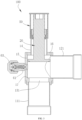
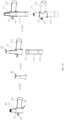
FIG. 1 is a schematic diagram of a stop valve of one or more embodiments. -
FIG. 2 is a cross-sectional schematic view of a stop valve of one or more embodiments. -
FIG. 3 is a cross-sectional schematic diagram of a stop valve in a front view of one or more embodiments. -
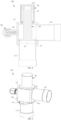
FIG. 4 is an exploded view of a stop valve of one or more embodiments. -
FIG. 5 is an exploded cross-sectional schematic view of a stop valve of one or more embodiments. -
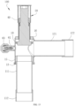
FIG. 6 is a cross-sectional schematic view of a stop valve in an opened state in one or more embodiments. -
FIG. 7 is a partial enlargement view of portion A inFIG. 6 . -
FIG. 8 is a cross-sectional schematic view of a stop valve in a closed state in one or more embodiments. -
FIG. 9 is a schematic diagram of a stop valve of one or more embodiments. -
FIG. 10 is an exploded cross-sectional schematic view of a stop valve of one or more embodiments. -
FIG. 11 is an exploded view of a stop valve of one or more embodiments. -
FIG. 12 is an exploded cross-sectional schematic view of a stop valve of one or more embodiments. -
FIG. 13 is an exploded view of a stop valve of one or more embodiments. -
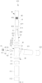
FIG. 14 is a cross-sectional schematic view of a stop valve of one or more embodiments. -
FIG. 15 is a cross-sectional schematic diagram of a stop valve in a front view in one or more embodiments. -
FIG. 16 is a schematic diagram of a stop valve of one or more embodiments. -
FIG. 17 is a schematic diagram of a process of normally installing a valve core of one or more embodiments. -
FIG. 18 is a schematic diagram of a process of reservedly installing a valve core of one or more embodiments. - 100 represents a stop valve; 10 represents a valve seat; 11 represents a first opening; 111 represents a first communication pipe; 112 represents a first connection pipe; 12 represents a second opening; 121 represents a second communication pipe; 122 represents a second connection pipe; 13 represents a collar; 131 represents a valve port; 132 represents a second limiting portion; 133 represents a second protrusion; 14 represents a sleeve; 15 represents a base; 151 represents a first segment; 1511 represents a first installing opening; 1512 represents a first limiting portion; 152 represents a main body segment; 153 represents a second segment; 1531 represents a second positioning portion; 154 represents a second installing opening; 16 represents a connection ring; 17 represents a step; 20 represents a valve core; 21 represents an operation segment; 211 represents a groove; 22 represents a connection segment; 221 represents a first sealing component; 222 represents a first protrusion; 223 represents a first sealing groove; 224 represents a third sealing component; 23 represents an abutting segment; 231 represents a second sealing component; 232 represents a second sealing groove; 30 represents a support; 31 represents a first positioning portion; 40 represent an end cover; 401 represents a third protrusion; 50 represents a protective sleeve; 60 represents a valve assembly; 61 represents a connector; 62 represents a valve spool; 63 represents a housing cover; 64 represents a fourth sealing component; 65 represents an elastic component; and 70 represents a valve body.
- The following will provide a clear and complete description of the technical solution in the embodiments of the present application, in communication with the accompanying drawings. Obviously, the described embodiments are only a part of the embodiments of the present application, not all of them. Based on the embodiments in the present application, all other embodiments obtained by ordinary skill in this art without creative labor fall within the scope of protection of the present application.
- It should be noted that, when a component is considered "set on" another component, it can be directly set on another component or there may be a centered component present simultaneously. When a component is considered "disposed on" another component, it can be directly fixed to another component or there may be a centered component present simultaneously. When a component is considered "fixed to" another component, it can be directly fixed to another component or there may be a centered component present simultaneously.
- Unless otherwise defined, all technical and scientific terms used in this article have the same meanings as those commonly understood by those skilled in the technical field of the present application. The terms used in the specification of the present application are only for the purpose of describing specific embodiments and are not intended to limit the present application. The term "or/and" used in this article includes any and all combinations of one or more related listed items.
- Referring to
FIGs. 1 to 18 , the present application provides astop valve 100. Thestop valve 100 is installed in a refrigeration system and capable of communicating pipelines and cutting off a communication of the pipelines. - Referring to
FIGs. 12 and13 , thestop valve 100 includes avalve body 70 and avalve core 20. At least part of thevalve core 20 is disposed in and capable of moving in thevalve body 70. Thevalve body 70 includes avalve seat 10. Thevalve body 70 and thevalve core 20 are both made of stainless steel, which can reduce a cost. - In particular, referring to
FIGs. 2 ,3 ,6 ,9 and12 , thevalve body 70 includes thevalve seat 10. Thevalve seat 10 is in a hollow structure, which is configured to accommodate components such as thevalve core 20 and so on. At least part of thevalve core 20 is disposed in thevalve seat 10 and capable of moving along an axis of thevalve seat 10. In the present embodiment, thevalve core 20 can be made of stainless steel. In other embodiments, thevalve core 20 can be made of copper. - The
valve seat 10 is provided with afirst opening 11 and asecond opening 12. Afirst communication pipe 111 is provided in thefirst opening 11. Asecond communication pipe 121 is provided in thesecond opening 12. When thefirst communication pipe 111 is defined as an inlet of a medium, thesecond communication pipe 121 is defined as an outlet of the medium. Alternatively, when thefirst communication pipe 111 is defined as an outlet of the medium, thesecond communication pipe 121 is defined as an inlet of the medium. When thefirst communication pipe 111 is defined as the inlet of the medium, the medium enters to thestop valve 100 from thefirst communication pipe 111, and enters into thevalve seat 10 through thefirst opening 11. If thestop valve 100 is opened, the medium passes through thesecond opening 12 and flows out of thestop valve 100 through thesecond communication pipe 121. Alternatively, the medium can enter into thevalve seat 10 through the second opening from thesecond communication pipe 121, and flow out of thestop valve 100 through thefirst opening 11 and thefirst communication pipe 111. - An end of the
first communication pipe 111 away from thevalve body 70 is provided with afirst connection pipe 112, thefirst communication pipe 111 and thefirst connection pipe 112 are separately arranged and fixedly connected, and thefirst connection pipe 112 is configured to be connected to an external pipeline. By thefirst communication pipe 111 and thefirst connection pipe 112 being separately arranged, thefirst communication pipe 111 and thefirst connection pipe 112 are capable of being formed by dimensionally formed pipe fittings, respectively, which can save a material. - The
first connection pipe 112 is made of copper. Thefirst communication pipe 111 is made of stainless steel, and thefirst connection pipe 112 is fixed with thefirst communication pipe 111 by welding. Since air condition pipelines are made of copper, thefirst connection pipe 112 made of copper is conducive to being connected to the air condition pipelines by welding. - The
first connection pipe 112 is sleeved on an outer wall of an end of thefirst communication pipe 111, and an inner size of thefirst connection pipe 112 is greater than that of thefirst communication pipe 111. By such arrangement, on one hand, a contact area between thefirst connection pipe 112 and thefirst communication pipe 111 increases, and a welding strength increases; on the other hand, when thestop valve 100 is connected to the external pipeline, an end of the external pipeline is inserted into thefirst connection pipe 112, which is capable of enabling an inner size of thefirst communication pipe 111 to be consistent with that of the external pipeline. - An end of the
second communication pipe 121 away from thevalve body 70 is provided with asecond connection pipe 122. Thesecond communication pipe 121 and thesecond connection pipe 122 are separately arranged and fixedly connected, and thesecond connection pipe 122 is configured to be connected to the external pipeline. By arranging thesecond communication pipe 121 and thesecond connection pipe 122 separately, thesecond communication pipe 121 and thesecond connection pipe 122 are formed by the dimensionally formed pipe fittings, respectively, saving the material and reducing cost. - The
second connection pipe 122 is made of copper, thesecond communication pipe 121 is made of stainless steel, and thesecond connection pipe 122 is fixed with thesecond communication pipe 121 by welding. Since the air condition pipelines are made of copper, thesecond connection pipe 122 made of copper is conducive to being connected to the air condition pipelines by welding. - The
second connection pipe 122 is sleeved on an outer wall of an end of thesecond communication pipe 121, and an inner size of thesecond connection pipe 122 is greater than that of thesecond communication pipe 121. By such arrangement, on one hand, a contact area between thesecond connection pipe 122 and thesecond communication pipe 121 increases, and the welding strength increases; on the other hand, when the stop valve is connected to the external pipeline, an end of the external pipeline is inserted into thesecond connection pipe 122, which is capable of enabling an inner size of thefirst communication pipe 111 to be consistent with that of the external pipe. - By such arrangement, the
first communication pipe 111 and thefirst connection pipe 112 are separately arranged, thefirst communication pipe 111 and thefirst connection pipe 112 are capable of being formed by the dimensionally formed pipe fittings, result in saving a material and reducing a cost. Alternatively, thesecond communication pipe 121 and thesecond connection pipe 122 are capable of being formed by the dimensionally formed pipe fittings, result in saving a material and reducing a cost. - In the present application, an inner wall of the
valve seat 10 is provided with astep 17, thestep 17 is provided with avalve port 131, thevalve port 131 is in communication with and coaxial with thefirst opening 11. When thevalve core 20 is inserted into thevalve port 131, a communication between the first opening and thesecond opening 12 being cut off can be realized. In the present application, thevalve port 131 is disposed on thevalve seat 10 to reduce welding processes. In other embodiments, acollar 13 can be separately provided in thevalve seat 10, and an end of thecollar 13 towards thevalve core 20 is formed thevalve port 131. - The
valve seat 10 is made of stainless steel. Thevalve seat 10 includes abase 15 and asleeve 14. At least part of thevalve core 20 is located in thesleeve 14 and extends into thebase 15. Thebase 15 and thesleeve 14 are separately arranged and fixedly connected. Alternatively, thefirst communication pipe 111 and thesecond communication pipe 121 are fixed on thebase 15 by welding, respectively. By such arrangement, an inner size of the base 15 can be adjusted as required, thereby realizing a function of a large diameter flow rate. In addition, since the cost of stainless steel is relatively low, thevalve seat 10 made of stainless steel can reduce cost. Furthermore, since the stainless steel is relatively hard, thevalve seat 10 is segmented, which is conducive to processing. Thebase 15 and thesleeve 14 are capable of being used instop valves 100 of different structures, versatility is excellent and flexibility is high. Thereby, a problem of stress concentration of a transition portion between the base 15 and thesleeve 14 when thevalve seat 10 is integrally made by copper can be prevented and it will not be prone to crack. - Referring to
FIG. 12 , thevalve seat 10 is provided with acollar 13, thevalve port 131 is formed on thecollar 13, and thevalve port 131 is in communication with thefirst opening 11. In some embodiments, thevalve port 131 is in communication with and coaxial with thefirst opening 11. When thevalve core 20 abuts against thecollar 13, a communication between thefirst opening 11 and thesecond opening 12 can be cut off. - A diameter of an opening of the
valve seat 10 towards thecollar 13 is greater than an outer size of thevalve core 20, facilitating installing thevalve core 20 from such opening. - Referring to
FIGs. 10 and11 , in the present embodiment, thecollar 13 is made of stainless steel, and thecollar 13 and thevalve seat 10 are separately arranged and fixedly connected. Since the stainless steel is relative hard, thecollar 13 and thevalve seat 10 are separately arranged, which is conducive to processing and reducing cost. In addition, thevalve seat 10 and thecollar 13 are capable of being used in stop valves of different structures, facilitating versatility and flexibility. Furthermore, thecollar 13 and the base 15 are capable of being processed and formed by the pipe fittings, thereby reducing a generation of a waste material. - An inner wall of an end of the
collar 13 towards thefirst communication pipe 111 is provided with a second limitingportion 132. Thefirst communication pipe 111 abuts against the second limitingportion 132 to restrict a length of thefirst communication pipe 111 inserting into thecollar 13. - In the present application, the second limiting
portion 132 can be a step surface. In other embodiments, the second limitingportion 132 can be a structure such as a protrusion and so on. - Alternatively, the
collar 13 can be fixed on thevalve seat 10 by welding, which is capable of improving a firmness of thestop valve 100. - An inner size of the
base 15 is greater than that of thesleeve 14, thereby saving a material of thesleeve 14. - Alternatively, the
base 15 is fixed with thesleeve 14 by welding, thereby improving a firmness of thestop valve 100. - The
base 15 is formed by a cold heading processing. Thesleeve 14 is formed by stainless steel pipes. The stainless steel pipes are ready-made for easy processing. Since thesleeve 14 is directly made of stainless steel pipes, a portion processed by cold heading is correspondingly shortened, a difficulty of the cold heading process is reduced, thevalve seat 10 has a small deformation, while alleviating a problem of stress concentration, which is not prone to crack. By such arrangement, it can reduce a generation of a waste material. - Referring to
FIGs. 1 ,4 and5 , thebase 15 includes amain body segment 152 and afirst segment 151, and themain body segment 152 is connected to and integrated with thefirst segment 151. Thefirst segment 151 is provided on a surface of an end of themain body segment 152 towards thesleeve 14, thefirst segment 151 protrudes relative to an end surface of themain body segment 152, thefirst segment 151 is configured to be connected to thesleeve 14, and a diameter of the circumscribed circle of thefirst segment 151 is less than that of themain body segment 152, thereby saving a material. - The
first segment 151 is in a ring shape and provided with afirst installing opening 1511. Themain body segment 152 is in a hollow structure. The first installing opening is in communication with themain body segment 152. Thesleeve 14 extends into thefirst installing opening 1511. - The base 15 further includes a
second segment 153. Themain body segment 152 is connected to and integrated with thesecond segment 153. Thesecond segment 153 is provided on an end surface of an end of themain body segment 152 away from thefirst segment 151. Thesecond segment 153 protrudes relative to an end surface of themain body segment 152. A diameter of a circumscribed circle of thesecond segment 153 is less than that of a circumscribed circle of themain body segment 152. Thesecond segment 153 is configured to fix thebase 15 by fitting with other components. - In the present embodiment, the
main body segment 152 is in a square shape, thefirst segment 151 is in a ring shape, and thesecond segment 153 is in a column shape. In other embodiments, themain body segment 152 can be in a circle shape, thefirst segment 151 can be in a square ring shape, and thesecond segment 153 can be in a prismatic shape. - The
valve seat 10 further includes aconnection ring 16, theconnection ring 16 is sleeve on an outer wall of an end of thesleeve 14, theconnection ring 16 is disposed in thefirst installing opening 1511 and fixedly connected to an inner wall of thefirst installing opening 1511. Theconnection ring 16 is disposed between the base 15 and thesleeve 14, a side of theconnection ring 16 towards thesleeve 14 is fixedly connected to thesleeve 14, a side of theconnection ring 16 away from thesleeve 14 is fixedly connected to thebase 15, and an outer size of thesleeve 14 is less than that of thebase 15. In addition, by such arrangement, an arrangement of theconnection ring 16 is capable of reducing both a width of thesleeve 14 and a width of thevalve core 20, thereby saving a material. Furthermore, a material of a sealing component in thesleeve 14 is saved, thereby saving a material and reducing a process difficulty, as long as thesleeve 14 plays a guiding role in thevalve core 20. Thebase 15 is relatively big, which is capable of increasing a flow rate of the medium. - In other embodiments, the
connection ring 16 can further be sleeved on thefirst installing opening 1511 and fixedly connected to an outer wall of thefirst installing opening 1511. - The
connection ring 16 and the base 15 are separately arranged. Theconnection ring 16 and thesleeve 14 are separately arranged. Since theconnection ring 16 and the base 15 are both made of stainless steel, the stainless steel is relatively hard, and such arrangement is conducive to being processed. Since sizes of theconnection ring 16, thesleeve 14 and the base 15 are different, theconnection ring 16, thesleeve 14 and the base 15 are capable of being individually processed by the stainless steel pipes, which is capable of further reducing the generation of the waste material, saving a cost and reducing processes. Thereby, when thevalve seat 10 is integrally made by copper, a problem of stress concentration of a transition portion between the base 15 and thesleeve 14 can be prevented and it in not prone to crack. Similarly, theconnection ring 16, thesleeve 14 and the base 15 are capable of using in thestop valves 100 of different specifications, thereby strengthening the flexibility of thestop valve 100. - The
base 15 is formed by flipping on two sides thereof after cutting the stainless steel pipes, and thesleeve 14 is formed by dimensionally formed pipe fittings, and a process is not required. - The
connection ring 16 is fixed with thebase 15 and thesleeve 14 by welding, thereby strengthening a firmness of a connection. - Alternatively, the
connection ring 16 is fixedly connected to an inner wall of thefirst installing opening 1511 by welding, thereby strengthening the firmness of the connection. A protrudedfirst segment 151 is capable of increasing a contact area between theconnection ring 16 and thebase 15, which is conducive for allowing solder to flow, and facilitating a firmness of a weld. - An inner wall of the
first installing opening 1511 is provided with a first limitingportion 1512, and theconnection ring 16 abuts against the first limitingportion 1512 to locate theconnection ring 16. - In the present embodiments, the first limiting
portion 1512 is a ring-shaped step surface. In other embodiments, the first limitingportion 1512 can be a protrusion. - An end surface of the
connection ring 16 towards an inner part of themain body segment 152 is in flush with an end surface of thesleeve 14 towards an inner part of themain body segment 152, such that a length of thesleeve 14 inserting into thefirst installing opening 1511 is appropriate, thereby preventing thesleeve 14 from inserting too deep and obstructing thevalve core 20. - Furthermore, an end surface of the
connection ring 16 away from themain body segment 152 protrudes relative to an end surface thefirst segment 151 away from themain body segment 152. Alternatively, the end surface of theconnection ring 16 away from themain body segment 152 is in flush with the end surface of thefirst segment 151 away from themain body segment 152, thereby increasing a contact area between theconnection ring 16 and thebase 15 and improving sealing performance and weld strength. - The
stop valve 100 further includes asupport 30, thesupport 30 is in a ring shape, sleeved outside the base, and fixedly connected to thebase 15, and thesupport 30 and the base 15 are separately arranged. Thesupport 30 is capable of using in thestop valves 100 of different specifications, facilitating a flexibly of thestop valve 100. - The
support 30 is fixedly connected to thebase 15 by welding, which is conducive to being processed. Thesupport 30 is made of stainless steel, since the stainless steel is relatively hard, such arrangement between thesupport 30 and thebase 15 is convenient to be processed, and a cost is reduced. - Alternatively, the
support 30 is sleeved outside thesecond segment 153 and abuts against themain body segment 152. Thesupport 30 plays a support role in themain body segment 152, and the base 15 can be installed and fixed by thesupport 30. - Referring to
FIGs. 3 and4 , an inner wall of thesupport 30 is provided with afirst positioning portion 31, an outer wall of thesecond segment 153 is provided with asecond positioning portion 1531, and thesupport 30 and thesecond segment 153 are located and installed by thefirst positioning portion 31 and thesecond positioning portion 1531. When thesupport 30 is welded to thesecond segment 153, thefirst positioning portion 31 fits with thesecond positioning portion 1531 to play a role of limiting, which prevents thesupport 30 from rotating, and an external tool for clamping thesupport 30 is not required. - In the present embodiment, the
first positioning portion 31 and thesecond positioning portion 1531 are both planes, a plane of thesupport 30 is in contact with a plane of thesecond segment 153. In other embodiments, thefirst positioning portion 31 and thesecond positioning portion 1531 can be a protrusion and other structures. - In some embodiments, the
valve body 70 further includes anend cover 40, and theend cover 40 is disposed at an end of thevalve seat 10. - In particular, two ends of the
sleeve 14 are individually provided with openings, an opening of thesleeve 14 away from thebase 15 is provided with anend cover 40. Theend cover 40 is provided with an inner thread, an end of thevalve core 20 is provided with an outer thread, by a thread cooperation between the inner thread of theend cover 40 and the outer thread of thevalve core 20, it can realize a movement of thevalve core 20 along an axis of thevalve core 20. - An end of the
end cover 40 penetrates throughvalve seat 10 and theend cover 40 andvalve seat 10 are separately arranged, and theend cover 40 is fixedly connected to thevalve seat 10. By arranging thevalve seat 10 and theend cover 40 separately, during a process, thevalve seat 10 and theend cover 40 are formed by pipe fittings, respectively. A design of thevalve body 70 with multi-segment can reduce the generation of the waste material, save the cost, and reduce the processes. In addition, since theend cover 40 and thevalve seat 10 are both made of stainless steel, the stainless steel is relatively hard, and such arrangement is conducive to being processed. Theend cover 40 and thevalve seat 10 are capable of being used in thestop valves 100 of different specifications, facilitating flexibility of thestop valves 100, and improving versatility of thestop valves 100. - The
valve core 20 includes aconnection segment 22 and anoperation segment 21 connected to each other. Theoperation segment 21 penetrates through theend cover 40. An outer thread is located on theoperation segment 21. An end surface of an end of theoperation segment 21 away from thebase 15 is provided with agroove 211. Thegroove 211 is provided with at least two planes parallel to each other, so as to allow the external tool to operate thevalve core 20 to rotate. In some embodiments, at least part of theconnection segment 22 is disposed in thesleeve 14. - The groove is provided with six planes interconnected to each other, so as to allow a hex-wrench to operate.
- An outer wall of the
connection segment 22 is provided with afirst sealing component 221, thefirst sealing component 221 abuts against an inner wall of thesleeve 14, and a material of thefirst sealing component 221 can be saved by providing theconnection ring 16. - Two sides of the
first sealing component 221 are provided withfirst protrusions 222. Afirst sealing groove 223 is formed by thefirst protrusions 222 on two sides of thefirst sealing component 221. Thefirst protrusion 222 towards theend cover 40 is provided with athird sealing component 224. Thethird sealing component 224 is capable of abutting against theend cover 40. When the stop valve is fully opened, thethird sealing component 224 abuts against the end cover to play a role of buffering and limiting. - Referring to
FIG. 12 , in some embodiments, an outer wall of theconnection segment 22 is provided with athird sealing component 224. An outer wall of theoperation segment 21 is provided with afirst protrusion 222. Thethird sealing component 224 is disposed on thefirst protrusion 222. An end of theend cover 40 is provided with athird protrusion 401. Thethird protrusion 401 is capable of abutting against thethird sealing component 224 to play a role of buffering and limiting. - Alternatively, a side surface of the
third protrusion 401 towards thethird sealing component 224 is an arc surface, thereby improving firmness between thethird protrusion 401 and thethird sealing component 224. - A
first sealing groove 223 is formed between thefirst protrusion 222 and theconnection segment 22. Thefirst sealing component 221 is provided in thefirst sealing groove 223. - The
valve core 20 further includes an abuttingsegment 23. An outer size of the abuttingsegment 23 is greater than an outer size of theconnection segment 22. When thestop valve 100 is closed, the abuttingsegment 23 abuts against thestep 17 and is capable of sealing thevalve port 131. An outer size of theconnection segment 22 is relatively less, which can save the material. In some embodiments, the abuttingsegment 23 is disposed on thebase 15 and connected to theconnection segment 22. When thestop valve 100 is closed, the abuttingsegment 23 abuts against thecollar 13 to seal thevalve port 131. - Referring to
FIGs. 7 and8 , a side surface of the abuttingsegment 23 towards thevalve port 131 is provided with asecond sealing component 231. Thesecond sealing component 231 is capable of abutting against thestep 17, facilitating a sealing performance for thevalve port 131. - An end surface of the
collar 13 towards thevalve core 20 is provided with asecond protrusion 133. Thesecond sealing component 231 is capable of abutting against thesecond protrusion 133, thereby improving a sealing performance of thevalve port 131. - The
second sealing component 231 is a copper gasket or a sealing gasket, since the copper gasket and the sealing gasket are both soft, facilitating a sealing performance of thestop valve 100. - A side surface of the abutting
segment 23 towards thevalve port 131 is provided with asecond sealing groove 232. Thesecond sealing component 231 is disposed in thesecond sealing groove 232. Thesecond sealing groove 232 is in a ring shape. A groove opening of thesecond sealing component 232 is in a necking structure, i.e., a width of the groove opening of thesecond sealing groove 232 is less than a width of a groove bottom of thesecond sealing groove 232, such that thesecond sealing component 231 is capable of being tightly snapped in thesecond sealing groove 232 and not easy to fall out. - Alternatively, a cross section of the
second sealing groove 232 is in a trapezium shape, which is conducive to being processed. - Furthermore, the
second protrusion 133 is in a ring shape and encircles a periphery of thevalve port 131. Alternatively, thesecond protrusion 133 is multiple, a plurality of thesecond protrusions 133 are evenly arranged around the periphery of thevalve port 131. - Along a direction towards the
valve core 20, a thickness of thesecond protrusion 133 is gradually decreased, such that an end of thesecond protrusion 133 towards thevalve core 20 is relatively sharp, which can be embedded into thesecond sealing component 231. By such arrangement, the sealing performance of thestop valve 100 is strengthened. - In the present embodiment, a side surface of the
second protrusion 133 away from thevalve core 131 is inclined relative to an axis of thevalve port 131. Along a direction towards thevalve core 20, a distance between a side surface of thesecond protrusion 133 away from thevalve port 131 and an axis of thevalve port 131 is gradually decreased, and an inner side surface of thesecond protrusion 133 towards thevalve port 131 is in flush with a wall surface of thevalve port 131. In other embodiments, a side surface of thesecond protrusion 133 towards thevalve port 131 and a side surface of thesecond protrusion 133 away from thevalve port 131 can both be inclined relative to the axis of thevalve port 131. Alternatively, the side surface of thesecond protrusion 133 towards thevalve port 131 is inclined relative to the axis of thevalve port 131, and a side surface of thesecond protrusion 133 away from thevalve port 131 is parallel to the axis of thevalve port 131. - A height h of the
second protrusion 133 is in a range of 0.5 mm to 5 mm, such that the height h of thesecond protrusion 133 is an appropriate value. If thesecond protrusion 133 is too high, a material is wasted. And if thesecond protrusion 133 is too low, a sealing performance may be infected. The height of thesecond protrusion 133 can be 0.5 mm, 1 mm, 2 mm, 3 mm, 4 mm or 5 mm. - The
stop valve 100 further includes aprotective sleeve 50, theprotective sleeve 50 is sleeved outside thesleeve 14, so as to play a protective role for thevalve core 20, thereby preventing an outer thread of theoperation segment 21 from falling dust and entering to thesleeve 14, and while preventing the dust from accumulating in thegroove 211. - In addition, the
stop valve 100 further includes avalve assembly 60, a side of thebase 15 is provided with a second installing opening 154, and an end of thevalve assembly 60 is inserted into the second installing opening 154 and is fixedly connected to an inner wall of thesecond installing opening 154. - In the present embodiment, the
valve assembly 60 is connected to themain body segment 152. Thevalve assembly 60 is opposite to thesecond opening 12, which is defined as an inflation inlet or deflation outlet and configured to supply or release the medium for the overall refrigerant system. In other embodiments, an axis of thevalve assembly 60 can be perpendicular to an axis of thesecond opening 12, and thevalve assembly 60 can be disposed at other portions of thebase 15. - In other embodiments, the
valve assembly 60 is not required. - The
valve assembly 60 includes aconnector 61, theconnector 61 is connected to thevalve seat 10 and the second installing opening 154, and theconnector 61 is a channel for the medium entering to thevalve seat 10. - The
connector 61 is made of stainless steel and theconnector 61 and the base 15 are separately arranged, which is conducive to being processed. Thevalve assembly 60 is used in thestop valves 100 of different specifications, facilitating the flexibility of the stop valves. - The
valve assembly 60 further includes avalve spool 62, ahousing cover 63 and afourth sealing component 64. Thevalve spool 62 is provided in theconnector 61 and capable of communicating themain body segment 152 with theconnector 61 or cutting off a communication between themain body segment 152 and theconnector 61. Thehousing cover 63 is sleeved on an outer periphery of theconnector 61 and configured to protect thevalve spool 62, thereby preventing external impurities from entering to thestop valve 100. Thefourth sealing component 64 is located between thehousing cover 61 and theconnector 61 and fits with the housing cover to seal theconnector 61. - In particular, an end of the
valve spool 62 is provided with anelastic component 65. When thevalve spool 62 does not suffer from external pressure, thevalve spool 62 is closed, and at this time, theconnector 61 is sealed to block an interior of thevalve seat 10 from external world. When thevalve spool 62 suffers from the external pressure, thevalve spool 62 compresses theelastic component 65 and moves along a direction towards thebase 15, thereby removing a blockage between the base 15 andconnector 61, such that thebase 15 is in communication with theconnector 16, and the medium can flow in or out thevalve core 10. Theelastic component 65 is configured to reset thevalve spool 62. - In some embodiments, during a process, a formed stainless steel pipes is used to process the
sleeve 14, thebase 15 is formed by cold heading stainless steel pipes or rods, theconnection ring 16 is sleeved on outer of thesleeve 14 and abuts against the first limitingportion 1512, and the connection ring is fixed on thebase 15 and thesleeve 14 by welding, respectively. During this process, thevalve core 20 is installed in the base 15 from thefirst installing opening 1511. - Meanwhile, the
support 30 and thevalve assembly 60 separately arranged are welded on thebase 15, respectively. By separately arranging and fixing each of components by welding, a process is convenient, problems of the stress concentration and being easy to crack can be solved, components separately arranged can be used in thestop valve 100 of other different structures, versatility and flexibility of thestop valve 100 are excellent. - In some embodiments, during a process, the
sleeve 14 is processed by the formed stainless steel pipes, thebase 15 is processed by the cold heading process, thecollar 13 formed by a machine is disposed in thebase 15. Thecollar 13, thebase 15, and thesleeve 14 are fixed on thebase 15 by welding. By providing thesecond protrusion 133 on thecollar 13, asecond sealing component 231 is provided on thevalve core 20. When thestop valve 100 is closed, thesecond sealing component 231 abuts against thesecond protrusion 133, thereby improving a sealing performance and preventing thestop valve 100 from causing an inner leakage. - In some embodiments, during a process, the
base 15, thesleeve 14 and theconnection ring 16 are formed by the pipe fittings and fixed to each other by welding, so material waste is less. Thefirst connection pipe 112 and thesecond communication pipe 122 are formed by the dimensionally formed pipe fittings, respectively, and fixed to each other by welding, and thesecond connection pipe 122 and thesecond communication pipe 121 are formed by the dimensionally formed pipe fittings, thereby reducing the generation of the waste material. - Referring to
FIG. 17 , during an installation process, in some embodiments, theconnector 61, thefirst communication pipe 111, thesecond communication pipe 121, thecollar 13, thesupport 30 and the base 15 are first fixedly connected to each other, i.e., lower half part of thestop valve 100 is installed, thevalve core 20 is installed into thebase 15, and thecollar 13 and thesleeve 14 are welded to thebase 15, thereby realizing a normal installation of thevalve core 20. In other embodiments, referring toFIG. 18 , thefirst communication pipe 111, thesleeve 14, theend cover 40, theconnector 61 and the base 15 are connected to each other, thevalve core 20 is installed from thefirst opening 11, and thecollar 13 and thesecond communication pipe 121 are installed, thereby realizing a reserved installation of thevalve core 20.Multi-stage valve body 70 is capable of enabling an installation process of thevalve core 20 to be flexible. - The various technical features of the above embodiments can be combined in any way. In order to make the description concise, not all possible combinations of the various technical features in the above embodiments have been described. However, as long as there is no contradiction in the combination of these technical features, they should be considered within the scope of this specification.
- The above embodiments only express several embodiments of the present application, and their descriptions are more specific and detailed, but should not be understood as limiting the scope of the utility model patent. It should be pointed out that for ordinary technical personnel in this field, several modifications and improvements can be made without departing from the concept of the present application, all of which fall within the scope of protection of the present application. Therefore, the scope of protection of the present patent application should be based on the attached claims.
Claims (15)
- A stop valve, characterized by comprising:a valve seat made of stainless steel, wherein the valve seat is at least provided with a first opening and a second opening; anda valve core,wherein at least part of the valve core is provided in the valve seat and capable of moving along an axis of the valve seat to communicate the first opening with the second opening or cut off a communication between the first opening and the second opening;the valve seat comprises a base and a sleeve, at least part of the valve core is located in the sleeve and extends into the base, the base and the sleeve are separately arranged and fixedly connected with each other.
- The stop valve of claim 1, wherein a collar is provided in the valve seat, the collar is provided with a valve port, the valve core is capable of moving along an axis of the valve seat to seal the port, and the collar and the valve seat are separately arranged.
- The stop valve of claim 2, wherein a second sealing component is provided at a side of the valve core towards the valve port, a second protrusion is provided at an end surface of the collar towards the valve core, the second sealing component is capable of abutting against the second protrusion; and
a second sealing groove in a ring shape is formed on a side surface of the valve core towards the valve port, the second sealing component is provided in the second sealing groove, a groove opening of the second sealing groove is in a necking structure. - The stop valve of claim 3, wherein along a direction towards the valve core, a thickness of the second protrusion is gradually reduced, and a height of the second protrusion is in a range of 0.5 mm to 5 mm.
- The stop valve of claim 3, wherein the valve core comprises a connection segment and an abutting segment, and the connection segment is connected to the abutting segment,the abutting segment is disposed towards the collar relative to the connection segment, the second sealing component is disposed on the abutting segment, an outer size of the abutting segment is greater than an outer size of the connection segment; and/oran inner size of the base is greater than an inner size of the sleeve, the abutting segment is located in the base, at least part of the connection segment penetrates through the sleeve.
- The stop valve of claim 1, wherein
the valve seat further comprises a connection ring, the connection ring is provided between the base and the sleeve, a side of the connection ring towards the sleeve is fixedly connected to the sleeve, a side of the connection ring away from the sleeve is fixedly connected to the base, and an outer size of the sleeve is less than an outer size of the base. - The stop valve of claim 6, wherein the connection ring and the base are separately arranged, the connection ring and the sleeve are separately arranged, the connection ring is sleeved on an outer wall of an end of the sleeve and fixedly connected to the sleeve; and an end of the base towards the sleeve is provided with a first installing opening, and the connection ring is inserted into the first installing opening and is fixed on an inner wall of the first installing opening.
- The stop valve of claim 1, wherein an inner size of the base is greater than an inner size of the sleeve, the valve seat further comprises a connection ring, the connection ring is sleeved on an outer wall of an end of the sleeve and fixedly connected to the sleeve, an end of the base towards the sleeve is provided with a first installing opening, the connection ring is inserted into the first installing opening and is fixedly connected to an inner wall of the first installing opening; and/or,
the connection ring and the base are separately arranged, the connection ring and the sleeve are separately arranged, an inner wall of the first installing opening is provided with a first limiting portion, and the connection ring abuts against the first limiting portion. - The stop valve of claim 8, wherein the base comprises a main body segment and a first segment, the first segment is disposed on the main body segment, the first installing opening is located on the first segment, an end surface of the connection ring away from the main body segment protrudes relative to an end surface of the first segment away from the main body segment, or an end face of the connecting ring away from the main body segment is in flush with an end face of the first segment away from the main body segment.
- The stop valve of claim 1, wherein the stop valve further comprises a support, the support is sleeved outside and fixedly connected to the base, and the support and the base are separately arranged;the base comprises a main body segment and a second segment, the second segment is disposed at an end of the main body segment, a diameter of a circumscribed circle of the second segment of the base is less than that of a circumscribed circle of the main body segment, the support is sleeved outside the second segment;an inner wall of the support is provided with a first positioning portion, an outer wall of the second segment is provided with a second positioning portion, the first positioning portion fits with the second positioning portion to locate both the support and the second segment.
- The stop valve of claim 6, further comprising an end cover, wherein the end cover is disposed on an end of the valve seat, the valve core penetrates through the end cover and is threadedly connected to the end cover, and the end cover and valve seat are separately arranged and fixedly connected.
- The stop valve of claim 11, wherein an end of the cover end is provided with a third protrusion, an outer wall of the valve core is provided with a first protrusion, the first protrusion is provided with a third sealing component, and the third sealing component is capable of abutting against the third protrusion.
- The stop valve of claim 6, wherein a first communication pipe is provided at the first opening, an end of the first communication pipe is provided with a first connection pipe, the first connection pipe is capable of being connected to external pipelines, the first communication pipe and the first connection pipe are separately arranged; and/or
a second communication pipe is provided at the second opening, an end of the second communication pipe is provided with a second connection pipe, the second connection pipe is capable of being connecting to external pipelines, the second communication pipe and the second connection pipe are separately arranged. - The stop valve of any one of claims 1, 2 and 6, wherein the base is formed by cold heading processing, and the sleeve is made of stainless steel; and/orthe base is formed by pipe fittings, and/or,the sleeve is formed by pipe fittings.
- The stop valve of claims 1 or 6, further comprising a valve assembly made of stainless steel, wherein a side surface of the base is provided with a second installing opening, an end of the valve assembly is inserted into the second installing opening and is fixedly connected to an inner wall of the second installing opening, and the valve assembly and the base are separately arranged and fixedly connected.
Applications Claiming Priority (4)
| Application Number | Priority Date | Filing Date | Title |
|---|---|---|---|
| CN202123214781.9U CN216742848U (en) | 2021-12-18 | 2021-12-18 | Stop valve |
| CN202123218667.3U CN216742849U (en) | 2021-12-18 | 2021-12-18 | Stop valve |
| CN202123220452.5U CN216742850U (en) | 2021-12-18 | 2021-12-18 | Stop valve |
| PCT/CN2022/139684 WO2023109957A1 (en) | 2021-12-18 | 2022-12-16 | Stop valve |
Publications (2)
| Publication Number | Publication Date |
|---|---|
| EP4450851A1 true EP4450851A1 (en) | 2024-10-23 |
| EP4450851A4 EP4450851A4 (en) | 2025-04-16 |
Family
ID=86774894
Family Applications (1)
| Application Number | Title | Priority Date | Filing Date |
|---|---|---|---|
| EP22906702.0A Pending EP4450851A4 (en) | 2021-12-18 | 2022-12-16 | Stop valve |
Country Status (4)
| Country | Link |
|---|---|
| EP (1) | EP4450851A4 (en) |
| JP (1) | JP2024543506A (en) |
| KR (1) | KR20240112977A (en) |
| WO (1) | WO2023109957A1 (en) |
Cited By (1)
| Publication number | Priority date | Publication date | Assignee | Title |
|---|---|---|---|---|
| EP4471304A4 (en) * | 2022-01-27 | 2025-05-07 | Zhejiang Dunan Artificial Environment Co., Ltd. | SHUT-OFF VALVE AND REFRIGERATION SYSTEM HAVING THE SAME |
Families Citing this family (1)
| Publication number | Priority date | Publication date | Assignee | Title |
|---|---|---|---|---|
| CN119617117A (en) * | 2023-09-14 | 2025-03-14 | 浙江盾安人工环境股份有限公司 | Stop valve and manufacturing method |
Family Cites Families (17)
| Publication number | Priority date | Publication date | Assignee | Title |
|---|---|---|---|---|
| US3382894A (en) * | 1966-04-11 | 1968-05-14 | Chatleff Controls Inc | Refrigeration valve and method and apparatus for making it |
| JPS5869161U (en) * | 1981-10-31 | 1983-05-11 | ダイキン工業株式会社 | Shutoff valve for room cooler |
| FR2664014B1 (en) * | 1990-06-28 | 1992-10-16 | Simonny Roger | TAP WITH INTERCHANGEABLE FLUID INLET AND OUTLET CONNECTION FOR CONSTITUTING EITHER A RIGHT TAP, EITHER A CORNER TAP. |
| DE19757117A1 (en) * | 1997-12-20 | 1999-06-24 | Bosch Gmbh Robert | Valve seat body fabrication method for fuel injection valve |
| DE102005061408A1 (en) * | 2005-12-22 | 2007-06-28 | Robert Bosch Gmbh | Combined plastic and metal component e.g. automotive fuel injection valve has serrated metal edge to plastic interface |
| CN201391610Y (en) * | 2009-02-13 | 2010-01-27 | 上海远东高中压阀门有限公司 | Abrasion-resistant and corrosion-resistant stop valve |
| JP5529175B2 (en) * | 2012-01-11 | 2014-06-25 | 千代田空調機器株式会社 | Valve device and method for manufacturing valve device |
| GB2517451A (en) * | 2013-08-20 | 2015-02-25 | Seetru Ltd | A valve sealing arrangement |
| JP6649055B2 (en) * | 2015-11-25 | 2020-02-19 | 株式会社キッツエスシーティー | High vacuum valve |
| CN110792787B (en) * | 2018-08-02 | 2022-06-17 | 浙江盾安禾田金属有限公司 | Stop valve |
| CN113785148B (en) * | 2019-05-15 | 2023-10-13 | 株式会社不二工机 | flow control valve |
| CN211501648U (en) * | 2019-11-01 | 2020-09-15 | 浙江盾安禾田金属有限公司 | Stop valve and valve body thereof |
| CN113007413A (en) * | 2019-12-18 | 2021-06-22 | 新昌县四通机电有限公司 | Valve body component, fluid control valve and manufacturing method |
| CN113700873A (en) * | 2021-09-29 | 2021-11-26 | 广东威灵电机制造有限公司 | Electronic expansion valve and refrigeration equipment |
| CN216742850U (en) * | 2021-12-18 | 2022-06-14 | 浙江盾安禾田金属有限公司 | Stop valve |
| CN216742849U (en) * | 2021-12-18 | 2022-06-14 | 浙江盾安禾田金属有限公司 | Stop valve |
| CN216742848U (en) * | 2021-12-18 | 2022-06-14 | 浙江盾安禾田金属有限公司 | Stop valve |
-
2022
- 2022-12-16 WO PCT/CN2022/139684 patent/WO2023109957A1/en not_active Ceased
- 2022-12-16 EP EP22906702.0A patent/EP4450851A4/en active Pending
- 2022-12-16 JP JP2024529133A patent/JP2024543506A/en active Pending
- 2022-12-16 KR KR1020247022808A patent/KR20240112977A/en active Pending
Cited By (1)
| Publication number | Priority date | Publication date | Assignee | Title |
|---|---|---|---|---|
| EP4471304A4 (en) * | 2022-01-27 | 2025-05-07 | Zhejiang Dunan Artificial Environment Co., Ltd. | SHUT-OFF VALVE AND REFRIGERATION SYSTEM HAVING THE SAME |
Also Published As
| Publication number | Publication date |
|---|---|
| EP4450851A4 (en) | 2025-04-16 |
| WO2023109957A1 (en) | 2023-06-22 |
| JP2024543506A (en) | 2024-11-21 |
| KR20240112977A (en) | 2024-07-19 |
Similar Documents
| Publication | Publication Date | Title |
|---|---|---|
| EP4450851A1 (en) | Stop valve | |
| EP4471304A1 (en) | Stop valve and refrigeration system having same | |
| CN109424766B (en) | Rotary reversing valve | |
| KR20240110851A (en) | Stop valve and its refrigeration system | |
| EP4450852A1 (en) | Stop valve and air conditioning unit comprising same | |
| CN217381770U (en) | Valve assembly and stop valve thereof | |
| US20250109799A1 (en) | Stop valve | |
| CN216742848U (en) | Stop valve | |
| CN216742850U (en) | Stop valve | |
| CN216742849U (en) | Stop valve | |
| CN216742874U (en) | Stop valve and refrigerating system thereof | |
| CN216742847U (en) | Stop valve and refrigerating system thereof | |
| CN209943541U (en) | Three eccentric butterfly valves of a mouthful lug formula are swept in area | |
| EP4450854A1 (en) | Valve assembly, stop valve and refrigeration system having same | |
| CN216742875U (en) | Stop valve and refrigerating system thereof | |
| CN221221791U (en) | Pipeline coupling assembly, packaging structure thereof and coupling device comprising same | |
| CN219493378U (en) | High-temperature ball valve | |
| CN218992360U (en) | Electromagnetic valve | |
| CN223004491U (en) | One-way valve, heating and ventilation equipment outdoor unit and heating and ventilation equipment | |
| CN211117731U (en) | PE pipeline valve | |
| US12385569B2 (en) | Reversible electromagnetic valve, and air conditioning unit having same | |
| CN215410283U (en) | Angle valve capable of feeding and discharging water in same direction | |
| CN216743039U (en) | Inflating valve and stop valve thereof | |
| CN219712419U (en) | Electric ball valve with multiple pipe ports connected | |
| CN220850937U (en) | Valve convenient to connect |
Legal Events
| Date | Code | Title | Description |
|---|---|---|---|
| STAA | Information on the status of an ep patent application or granted ep patent |
Free format text: STATUS: THE INTERNATIONAL PUBLICATION HAS BEEN MADE |
|
| PUAI | Public reference made under article 153(3) epc to a published international application that has entered the european phase |
Free format text: ORIGINAL CODE: 0009012 |
|
| STAA | Information on the status of an ep patent application or granted ep patent |
Free format text: STATUS: REQUEST FOR EXAMINATION WAS MADE |
|
| 17P | Request for examination filed |
Effective date: 20240718 |
|
| AK | Designated contracting states |
Kind code of ref document: A1 Designated state(s): AL AT BE BG CH CY CZ DE DK EE ES FI FR GB GR HR HU IE IS IT LI LT LU LV MC ME MK MT NL NO PL PT RO RS SE SI SK SM TR |
|
| DAV | Request for validation of the european patent (deleted) | ||
| DAX | Request for extension of the european patent (deleted) | ||
| A4 | Supplementary search report drawn up and despatched |
Effective date: 20250317 |
|
| RIC1 | Information provided on ipc code assigned before grant |
Ipc: F25B 1/00 20060101ALI20250311BHEP Ipc: F16K 1/04 20060101ALI20250311BHEP Ipc: F16K 1/00 20060101AFI20250311BHEP |