EP4450822A1 - A cooling fan assembly - Google Patents
A cooling fan assembly Download PDFInfo
- Publication number
- EP4450822A1 EP4450822A1 EP23169287.2A EP23169287A EP4450822A1 EP 4450822 A1 EP4450822 A1 EP 4450822A1 EP 23169287 A EP23169287 A EP 23169287A EP 4450822 A1 EP4450822 A1 EP 4450822A1
- Authority
- EP
- European Patent Office
- Prior art keywords
- fans
- control rod
- fan
- fan assembly
- assembly
- Prior art date
- Legal status (The legal status is an assumption and is not a legal conclusion. Google has not performed a legal analysis and makes no representation as to the accuracy of the status listed.)
- Granted
Links
Images




Classifications
-
- F—MECHANICAL ENGINEERING; LIGHTING; HEATING; WEAPONS; BLASTING
- F04—POSITIVE - DISPLACEMENT MACHINES FOR LIQUIDS; PUMPS FOR LIQUIDS OR ELASTIC FLUIDS
- F04D—NON-POSITIVE-DISPLACEMENT PUMPS
- F04D29/00—Details, component parts, or accessories
- F04D29/26—Rotors specially for elastic fluids
- F04D29/32—Rotors specially for elastic fluids for axial flow pumps
- F04D29/34—Blade mountings
- F04D29/36—Blade mountings adjustable
-
- F—MECHANICAL ENGINEERING; LIGHTING; HEATING; WEAPONS; BLASTING
- F04—POSITIVE - DISPLACEMENT MACHINES FOR LIQUIDS; PUMPS FOR LIQUIDS OR ELASTIC FLUIDS
- F04D—NON-POSITIVE-DISPLACEMENT PUMPS
- F04D29/00—Details, component parts, or accessories
- F04D29/26—Rotors specially for elastic fluids
- F04D29/32—Rotors specially for elastic fluids for axial flow pumps
- F04D29/34—Blade mountings
- F04D29/36—Blade mountings adjustable
- F04D29/362—Blade mountings adjustable during rotation
-
- F—MECHANICAL ENGINEERING; LIGHTING; HEATING; WEAPONS; BLASTING
- F04—POSITIVE - DISPLACEMENT MACHINES FOR LIQUIDS; PUMPS FOR LIQUIDS OR ELASTIC FLUIDS
- F04D—NON-POSITIVE-DISPLACEMENT PUMPS
- F04D25/00—Pumping installations or systems
- F04D25/16—Combinations of two or more pumps ; Producing two or more separate gas flows
- F04D25/166—Combinations of two or more pumps ; Producing two or more separate gas flows using fans
-
- F—MECHANICAL ENGINEERING; LIGHTING; HEATING; WEAPONS; BLASTING
- F04—POSITIVE - DISPLACEMENT MACHINES FOR LIQUIDS; PUMPS FOR LIQUIDS OR ELASTIC FLUIDS
- F04D—NON-POSITIVE-DISPLACEMENT PUMPS
- F04D29/00—Details, component parts, or accessories
- F04D29/26—Rotors specially for elastic fluids
- F04D29/32—Rotors specially for elastic fluids for axial flow pumps
- F04D29/325—Rotors specially for elastic fluids for axial flow pumps for axial flow fans
- F04D29/329—Details of the hub
-
- F—MECHANICAL ENGINEERING; LIGHTING; HEATING; WEAPONS; BLASTING
- F04—POSITIVE - DISPLACEMENT MACHINES FOR LIQUIDS; PUMPS FOR LIQUIDS OR ELASTIC FLUIDS
- F04D—NON-POSITIVE-DISPLACEMENT PUMPS
- F04D29/00—Details, component parts, or accessories
- F04D29/26—Rotors specially for elastic fluids
- F04D29/32—Rotors specially for elastic fluids for axial flow pumps
- F04D29/38—Blades
- F04D29/384—Blades characterised by form
-
- A—HUMAN NECESSITIES
- A01—AGRICULTURE; FORESTRY; ANIMAL HUSBANDRY; HUNTING; TRAPPING; FISHING
- A01D—HARVESTING; MOWING
- A01D41/00—Combines, i.e. harvesters or mowers combined with threshing devices
- A01D41/12—Details of combines
Definitions
- the present invention is related to a cooling fan assembly for cooling the radiator of an internal combustion engine.
- the assembly according to the invention is in particular suitable for use in a large work machine such as a combine harvester.
- Cooling fans used in such configurations are usually of the axial flow type, having radially oriented blades which can be adjusted by adjusting the inclination angle, also referred to as the pitch of the blades. This adjustment allows to control the air flow rate and thereby the cooling power of the fan.
- the range of the pitch is such that the adjustment also allows to reverse the direction of the air flow, i.e. towards or away from the radiator. Reversing the air flow can be used to clean the accumulated dust / dirt in the radiator by blowing it out of the radiator.
- the dimensions and shape of the radiator may require the use of several cooling fans.
- Mechanisms for controlling the pitch can be hydraulic, pneumatic or mechanical.
- the hydraulic and pneumatic systems are reliable but expensive and technically complex, requiring high-quality sealing elements to avoid leakage of the working fluid.
- a known mechanical system is shown for example in patent publication document US3169582 , which discloses a system wherein the fan blades are mounted on rotatable cylinders actuated by small levers, the orientation of which can be controlled by changing the axial position of a positioning disc.
- the disc is axially coupled to a non-rotatable positioning rod extending outward from the fan.
- the blade pitch can be adjusted by moving the positioning rod along its axial direction, which could be done by coupling an electric actuator to the positioning rod.
- the invention is related to a cooling assembly as described in the appended claims.
- the assembly comprises two or more axial flow fans rotatably mounted on a support structure.
- the fans are of the adjustable pitch type, i.e. each fan includes an adjustment mechanism for adjusting the pitch of the blades, that is actuatable by axially shifting a positioning rod extending outward from the hub of the fan.
- a fan assembly further comprises a movable control member and a plurality of adjustment mechanisms coupled respectively to the positioning rods and to the control member in such a way that the position of the control member determines the axial position of the positioning rods and thereby the pitch of the blades of all the fans of the assembly.
- a single actuator is configured to actuate a movement of the control member, either directly or through a suitable transmission.
- the fan assembly is technically straightforward and less expensive than existing solutions.
- a single actuator commands the position of the blades of each fan of the assembly.
- the control member and the adjustment mechanisms for displacing the positioning rods represent a mechanical system for setting the blade pitch, requiring no extra hydraulic, pneumatic or electrical connections to the fans.
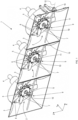
- FIG. 1 shows a cooling fan assembly 1 according to an embodiment of the invention, comprising three axial flow cooling fans 2 mounted side by side, for cooling the radiator (not shown) of an internal combustion engine of a large work machine such as a combine harvester, a forage harvester, a cotton harvester or a sugar cane harvester.
- the fans 2 have the same diameter in this embodiment but fans having different diameters are also possible as will be described later in this text.
- Each fan is mounted in a housing 3 having curved sidewalls for guiding the air flow generated by the fans 2.
- the cooling assembly 1 is configured to be mounted in front of the radiator of an internal combustion engine (not shown), the radiator having a rectangular surface corresponding more or less with the combined surface area of the adjacent housings 3 of the fans 2.
- Each of the cooling fans 2 comprises a rotation axle 4 configured to be coupled to a drive configuration generally known in the art, for example a belt drive, or a set of electric motors, preferably but not necessarily configured to drive the rotation of the fans 2 at the same rotational speed.
- the axles 4 are rotatably mounted on a support structure (not shown), which may be the housing of the engine or a separate support mounted on the chassis of the work machine.
- Each fan 2 comprises a hub 5, with fan blades 6 extending radially outward from the hub.
- the fan blades 6 are coupled to a mechanical system that is present inside the hub 5, for adjusting the pitch of the blades 6, i.e. the angular position of the blades about a radially oriented axis.
- each blade 6 is mounted on a rotatable cylinder, the rotation of which is controlled by said mechanical system.
- the system may for example be a mechanism involving levers and a control disc, as disclosed in US3169582 .
- the mechanism is actuated by changing the axial position of a non-rotatable positioning rod 7 mounted coaxially with respect to the rotation axle 4 of the fan.
- the range of the blade pitch is preferably large enough to enable the reversing of the flow direction of air flow generated by the fans 2, when the pitch is changed through its full range.
- the positioning rod 7 of each fan 2 is adjustable through an adjustment mechanism 9.
- this is a crank mechanism comprising a rotatable crank arm 10 and a connecting arm 11.
- the connecting arm 11 is rotatably coupled to the crank arm 10 at one end of said connecting arm 11 and to the positioning rod 7 at the other end, so that a rotation of the crank arm 10 about a fixed rotation axis 12 (i.e. fixed relative to the support structure) is translated into an axial displacement of the positioning rod 7, and hence to an adjustment of the pitch of the blades 6.
- crank arms 10 of the three crank mechanisms 9 are aligned and interconnected by a control rod 15.
- the control rod 15 is rotatably mounted with respect to the support structure and in the embodiment shown, passes through a front portion of the housings 3.
- the central axis 12 of the control rod 15 coincides with the rotation axes of the crank arms 10 of the three crank mechanisms.
- the three crank arms 10 are fixed to the control rod 15, so that a rotation of the control rod 15 about its central axis 12 actuates a simultaneous rotation of the crank arms 10 and thereby a simultaneous adjustment of the pitch of the blades 6 of the three fans 2.
- the control rod 15 is rotatably supported at at least two support points, for example at its two extremities, by suitable support means (not shown) such as rotary bearings or the like mounted in a fixed position relative to the support structure onto which the fans are mounted.
- suitable support means such as rotary bearings or the like mounted in a fixed position relative to the support structure onto which the fans are mounted.
- a lever 16 is attached to the control rod 15 at one extremity thereof.
- Figure 2 shows a parallel projection on the YZ plane of the fan assembly of Figure 1 , in particular of the means for setting the pitch of the blades 6.
- the fans as such are not shown in full in Figure 2 , which only partly shows the aligned hubs 5.
- the crank mechanisms are also fully aligned and operating in phase. In reality, there may be a misalignment or a phase difference between these mechanisms and/or a difference in the dimensions between corresponding elements, such as the crank arms 10, the connecting arms 11 or the axially movable positioning rods 7. What counts in this embodiment is that all the crank mechanisms 9 are coupled to the same control rod 15.
- the lever 16 is connected to an actuator 17 mounted on the support structure or on a surface 18 that is uniform with or fixed to said support structure, for example on the chassis of the work machine.
- the actuator 17 may be an electric motor configured to drive the rotation of a disc 19 mounted on the outlet axle 14 of the motor.
- a pin 20 is rotatably coupled to the disc 19 at one end of said pin and also rotatably coupled to the lever 16 at the other end, so that the angular position of the disc 19 controls the angular position of the lever 16 and thereby of the control rod 15.
- the disc 19 and pin 20 act as a further crank mechanism 21 configured to rotate the lever 16 and thereby the control rod 15.
- a single actuator 17 is used to control the pitch of the blades of all the fans of the assembly.
- the pitch of all the blades is adjustable through a single actuator and a reliable mechanical connection comprising, in the embodiment shown, a plurality of crank mechanisms 9 and a control rod 15. No hydraulic, pneumatic or electrical connections directly coupled to the fans are required.
- control rod 15 is rotated
- actuator used to actuate this rotation may be any suitable actuator known in the art, including hydraulic or pneumatic actuators.
- crank mechanism 21 including the disc 19 and pin 20
- the movement of the lever 16 can be actuated by any other suitable mechanism, for example by a variable length actuator that is rotatably mounted on the support structure, and coupled (also rotatably) to the lever 16.
- the rotation of the control rod 15 could be actuated by other means than the lever 16. Any suitable transmission could be mounted between the output axle 14 of actuator 17 and the control rod 15 for driving the rotation of the latter, for example a gear transmission or a belt drive. Another alternative is to place the actuator 17 at the same height as the control rod 15 and to directly couple said control rod 15 to the output axle 14 of the actuator 17.
- any other suitable mechanical adjustment mechanism may be used for displacing the positioning rods 7, for example a rack and pinion drive including a circular gear (pinion) coaxially fixed to the control rod 15 and a linear gear (rack) for transferring the rotation of the control rod 15 into an axial displacement of the positioning rod 7.
- a rack and pinion drive including a circular gear (pinion) coaxially fixed to the control rod 15 and a linear gear (rack) for transferring the rotation of the control rod 15 into an axial displacement of the positioning rod 7.
- Another transmission could include a worm drive with a worm wheel and a worm.
- the control rod 15 is not rotatable but it is displaceable axially in the direction of its longitudinal central axis 12.
- a fan assembly comprising two fans 2 of equal diameter positioned before a radiator whose surface area is delimited by the rectangle 29.
- the image shows only the hubs 5 of the fans and a larger circle indicating the outer diameter of the fans.
- the control rod 15 is slidably supported by two slide bearings 30 mounted on the support structure, symbolized in Figure 3 by the hatched areas 31. Also mounted on the support structure 31 is a variable length actuator 32. The actuator is connected to one extremity of the control rod 15 so as to drive an axial movement of the rod.
- the actuator 32 is a hydraulic variable length actuator with input and output ports 33 for a hydraulic fluid, configured to actively drive the movement of the rod 15 in either of the two opposite directions.
- it may be an electrically driven variable length actuator.
- Another alternative is to connect one extremity of the rod 15 to a single-direction hydraulic or electric variable length actuator and to couple the other extremity to a spring so that movement in one axial direction may be actuated by the actuator and the movement in the opposite direction may be actuated by the spring force.
- the control rod 15 could be replaced by a cable or wire tensioned between the actuator at one end and a suitably arranged spring at the other end. Both the control rod 15 (rotatable or displaceable axially) and a tensioned cable or wire are embodiments of the 'control member' referred to in the appended claims.
- the axially displaceable rod 15 (or cable/wire in alternative embodiments) is coupled to adjustment mechanisms 34, represented symbolically by squares in Figure 3 . These mechanisms are coupled also to the positioning rods 7 of the fans 2. These mechanisms are configured to transform an axial displacement of the rod 15 (or cable/wire) into an axial displacement of the positioning rods 7, i.e. in an axial displacement oriented essentially perpendicularly to the actuating displacement.
- adjustment mechanisms 34 represented symbolically by squares in Figure 3 .
- These mechanisms are coupled also to the positioning rods 7 of the fans 2.
- These mechanisms are configured to transform an axial displacement of the rod 15 (or cable/wire) into an axial displacement of the positioning rods 7, i.e. in an axial displacement oriented essentially perpendicularly to the actuating displacement.
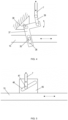
- Various possible embodiments of such mechanisms can be used here, two examples of which are illustrated in Figures 4 and 5 .
- the axially displaceable control rod 15 comprises an upwardly oriented pin 35 that is slidably arranged in a groove 36 provided in one leg of an L-shaped bracket 37.
- the bracket 37 is pivotable relative to the support structure 31 about upright pivot axis 38.
- a connecting arm 39 is rotatably coupled to the other leg of the bracket 37 at one end of said arm 39 and to the positioning rod 7 of one of the fans 2 at the other end of the arm 39.
- the axial displacement of the rod 15 is transferred to a rotation of the bracket 37 and hence to an axial shift of the positioning rod 7.
- brackets 37 of these mechanisms could be coupled to respective springs when the control rod 15 is coupled to a single-direction variable length actuator.
- the springs are then configured to actuate the axial movement of the rod in the direction opposite the direction of movement actuated by the actuator.
- the mechanism illustrated in Figure 5 includes a block 45 fixed to the axially displaceable rod 15.
- the block 45 is provided with a slanted groove 46 into which an upright pin 47 is slidably arranged.
- the pin 47 is attached to the positioning rod 7 of one of the fans 2.
- the pin 47 interacts with the groove 46 in the way of a cam system that transfers an axial displacement of the control rod 15 into an axial displacement of the positioning rod 7, the displacement of the positioning rod 7 being oriented perpendicularly to the displacement of the control rod 15.
- the fan assembly comprises a single control rod 15, while a component of each adjustment mechanism 9 or 34, for example the crank arm 10 in Figure 2 , or the block 45 in Figure 5 , is directly fixed to the control rod 15. While this is a straightforward embodiment in terms of the needed amount of components, it requires the fans 2 of the assembly to be placed more or less at the same height level.
- Figure 6 illustrates an embodiment wherein one of the fans 2, including its rotation axle, is located at a lower level than the other fans of the assembly.
- the fan assembly now includes an additional control rod 15', in addition to the main control rod 15 which is still directly coupled to the lever 16.
- the additional control rod 15' is essentially parallel to the main control rod 15, located below said main control rod 15 and rotatably coupled thereto by a transmission 50, in this case a toothed belt drive, although any other transmission can be used, for example a gear transmission.
- the transmission 50 drives the rotation of the additional control rod 15' at the same rotational speed as the main control rod 15, so that the adjustment of the blade pitch of the lower fan is performed at the same adjustment rate as the higher positioned fan or fans of the assembly.
- a speed difference may be applied, by applying a transmission that realizes a given speed ratio, for example a toothed belt drive including gear wheels of different diameter.
- FIG. 7 An variant of the embodiment of Figure 6 is illustrated in Figure 7 .
- This figure again uses a simplified frontal representation of the assembly, facing a radiator of circumference 29, and now comprising two fans 2 of different diameters and with the rotation axis of the smaller fan placed higher than the rotation axis of the larger fan.
- the main control rod 15 comprising the lever 16 at its outer end is indicated.
- the lever 16 is configured to be coupled to an actuator (not shown) in the manner described above or equivalent thereto, for actuating the rotation of the main control rod 15 about its central axis.
- the higher placed fan is again coupled to an additional control rod 15', but now the rotation of the main control rod 15 is transferred to the rotation of the additional rod 15' by a cardan shaft 51, connected to the main and additional rods 15,15' by respective universal joints 52 and 53.
- the control rods 15 and 15' are rotatable with respect to the support structure 31 via rotatable bearings 54.
- the cardan shaft 51 together with the universal joints 52,53 constitutes another embodiment of a transmission that transfers a rotation of the main control rod 15 to a rotation of the additional control rod 15'.
- Figure 8 illustrates an embodiment provided with an axially displaceable main control rod 15 coupled to a variable length actuator 32 as described above with reference to Figure 3 .
- the assembly also includes a larger fan and a smaller fan, the latter having its rotation axle at a higher level than the former.
- the main control rod 15 is coupled to the larger fan by an adjustment mechanism 34, which may be either of the mechanisms shown in Figures 4 or 5 or any equivalent thereto.
- the assembly comprises an additional control rod 15' coupled to the smaller fan by a further adjustment mechanism 34.
- the two control rods 15,15' are connected by a vertical interconnect 60.
- the interconnect 60 may also be referred to as a transmission, transmitting the axial displacement of the main control rod 15 to the same displacement of the additional rod 15', to thereby adjust the pitch of the two fans 2 simultaneously.
- the fans 2 of the fan assembly may have different diameters.
- Figure 9 illustrates a further embodiment wherein the surface area of the radiator, indicated by the rectangle 29 is such that it is difficult to cover it by fans having the same diameter.
- the solution shown in Figure 9 uses two fans 2 of the same diameter and an additional centrally placed fan 2 having a smaller diameter.
- the three fans 2 are coupled to a rotatable control rod 15 as described above, supported by two rotary bearings 54, and coupled to adjustment mechanisms 9 according to any one of the above-described embodiments.
- the control rod 15 comprises at one extremity the lever 16 coupled to a suitable mechanism (not shown) for driving the rotation of the control rod 15. Said mechanism may equally be in accordance with any one of the above-described embodiments.
- the adjustment mechanisms 9 or 34 for example the crank mechanisms 10,11 for adjusting the positioning rods 7 of the fans may have different dimensions, or different types of adjustment mechanisms may be used for different fans, in order for example to realize - by the same rotation or by the same axial displacement of the control rod 15 - a larger change in the blade pitch in one fan compared to another fan of the assembly, enabling a different air flow adjustment on different areas of the radiator.
- phase difference between the angular blade positions of different fans may be constant or variable depending on the exact configurations in terms of the types and dimensions of the adjustment mechanisms 9 or 34. Said phase difference may be zero so that all the fans always deliver the same air flow regardless of the position of the control member 15. Alternatively, a non-zero phase difference may be deliberately applied between two or more fans, enabling a difference in air flow rate. This also enables a sequential reversing of the flow direction when the fans are fully reversible, i.e. the fans sequentially reverse their flow direction, when the pitch of the blades is changed through its full range.
Landscapes
- Engineering & Computer Science (AREA)
- Mechanical Engineering (AREA)
- General Engineering & Computer Science (AREA)
- Structures Of Non-Positive Displacement Pumps (AREA)
Abstract
Description
- The present invention is related to a cooling fan assembly for cooling the radiator of an internal combustion engine. The assembly according to the invention is in particular suitable for use in a large work machine such as a combine harvester.
- Work machines are generally equipped with an internal combustion engine provided with a cooling system comprising a liquid coolant that flows through a cooling circuit. Coolant that is heated in the engine is cooled in a radiator by an air flow generated by a cooling fan. Cooling fans used in such configurations are usually of the axial flow type, having radially oriented blades which can be adjusted by adjusting the inclination angle, also referred to as the pitch of the blades. This adjustment allows to control the air flow rate and thereby the cooling power of the fan. Usually, the range of the pitch is such that the adjustment also allows to reverse the direction of the air flow, i.e. towards or away from the radiator. Reversing the air flow can be used to clean the accumulated dust / dirt in the radiator by blowing it out of the radiator. In large work machines such as combine harvesters, the dimensions and shape of the radiator may require the use of several cooling fans.
- Mechanisms for controlling the pitch can be hydraulic, pneumatic or mechanical. The hydraulic and pneumatic systems are reliable but expensive and technically complex, requiring high-quality sealing elements to avoid leakage of the working fluid. A known mechanical system is shown for example in patent publication document
US3169582 , which discloses a system wherein the fan blades are mounted on rotatable cylinders actuated by small levers, the orientation of which can be controlled by changing the axial position of a positioning disc. The disc is axially coupled to a non-rotatable positioning rod extending outward from the fan. The blade pitch can be adjusted by moving the positioning rod along its axial direction, which could be done by coupling an electric actuator to the positioning rod. - In current cooling systems involving multiple fans, the control of the blade pitch of the different fans is realized by separate control lines, either hydraulic/pneumatic or electric, which is however a technically complex and expensive solution.
- The invention is related to a cooling assembly as described in the appended claims. The assembly comprises two or more axial flow fans rotatably mounted on a support structure. The fans are of the adjustable pitch type, i.e. each fan includes an adjustment mechanism for adjusting the pitch of the blades, that is actuatable by axially shifting a positioning rod extending outward from the hub of the fan.
- A fan assembly according to the invention further comprises a movable control member and a plurality of adjustment mechanisms coupled respectively to the positioning rods and to the control member in such a way that the position of the control member determines the axial position of the positioning rods and thereby the pitch of the blades of all the fans of the assembly. A single actuator is configured to actuate a movement of the control member, either directly or through a suitable transmission.
- The fan assembly is technically straightforward and less expensive than existing solutions. A single actuator commands the position of the blades of each fan of the assembly. The control member and the adjustment mechanisms for displacing the positioning rods represent a mechanical system for setting the blade pitch, requiring no extra hydraulic, pneumatic or electrical connections to the fans.
-
-
Figure 1 is a 3D view of a cooling fan assembly according to an embodiment of the invention wherein the control member is a rotatable control rod. -
Figure 2 is a side view of the embodiment ofFigure 1 , including an actuator for adjusting the pitch of the blades of the fans. -
Figure 3 illustrates an alternative embodiment wherein the control member is an axially displaceable control rod. -
Figures 4 and 5 illustrate embodiments of a suitable adjustment mechanism for adjusting the position of the positioning rods of the fans, when the control rod is axially displaceable. -
Figure 6 is a side view of a pitch adjustment system of a fan assembly according to an embodiment of the invention, wherein one of the fans is mounted at a different height than the other fans of the assembly. -
Figures 7 and 8 illustrate further embodiments including fans placed at different heights. -
Figure 9 illustrates an embodiment including fans placed at the same height and having different diameters. - Preferred embodiments will now be described with reference to the drawings. The detailed description is not limiting the scope of the invention, which is defined only by the appended claims.
-
Figure 1 shows acooling fan assembly 1 according to an embodiment of the invention, comprising three axialflow cooling fans 2 mounted side by side, for cooling the radiator (not shown) of an internal combustion engine of a large work machine such as a combine harvester, a forage harvester, a cotton harvester or a sugar cane harvester. Thefans 2 have the same diameter in this embodiment but fans having different diameters are also possible as will be described later in this text. Each fan is mounted in ahousing 3 having curved sidewalls for guiding the air flow generated by thefans 2. Thecooling assembly 1 is configured to be mounted in front of the radiator of an internal combustion engine (not shown), the radiator having a rectangular surface corresponding more or less with the combined surface area of theadjacent housings 3 of thefans 2. - Each of the
cooling fans 2 comprises arotation axle 4 configured to be coupled to a drive configuration generally known in the art, for example a belt drive, or a set of electric motors, preferably but not necessarily configured to drive the rotation of thefans 2 at the same rotational speed. Theaxles 4 are rotatably mounted on a support structure (not shown), which may be the housing of the engine or a separate support mounted on the chassis of the work machine. - Each
fan 2 comprises ahub 5, withfan blades 6 extending radially outward from the hub. Thefan blades 6 are coupled to a mechanical system that is present inside thehub 5, for adjusting the pitch of theblades 6, i.e. the angular position of the blades about a radially oriented axis. To this aim, eachblade 6 is mounted on a rotatable cylinder, the rotation of which is controlled by said mechanical system. The system may for example be a mechanism involving levers and a control disc, as disclosed inUS3169582 . The mechanism is actuated by changing the axial position of anon-rotatable positioning rod 7 mounted coaxially with respect to therotation axle 4 of the fan. The range of the blade pitch is preferably large enough to enable the reversing of the flow direction of air flow generated by thefans 2, when the pitch is changed through its full range. - The
positioning rod 7 of eachfan 2 is adjustable through anadjustment mechanism 9. In the embodiment shown, this is a crank mechanism comprising arotatable crank arm 10 and a connectingarm 11. The connectingarm 11 is rotatably coupled to thecrank arm 10 at one end of said connectingarm 11 and to thepositioning rod 7 at the other end, so that a rotation of thecrank arm 10 about a fixed rotation axis 12 (i.e. fixed relative to the support structure) is translated into an axial displacement of thepositioning rod 7, and hence to an adjustment of the pitch of theblades 6. - It is seen furthermore that the
crank arms 10 of the threecrank mechanisms 9 are aligned and interconnected by acontrol rod 15. Thecontrol rod 15 is rotatably mounted with respect to the support structure and in the embodiment shown, passes through a front portion of thehousings 3. Thecentral axis 12 of thecontrol rod 15 coincides with the rotation axes of thecrank arms 10 of the three crank mechanisms. The threecrank arms 10 are fixed to thecontrol rod 15, so that a rotation of thecontrol rod 15 about itscentral axis 12 actuates a simultaneous rotation of thecrank arms 10 and thereby a simultaneous adjustment of the pitch of theblades 6 of the threefans 2. - The
control rod 15 is rotatably supported at at least two support points, for example at its two extremities, by suitable support means (not shown) such as rotary bearings or the like mounted in a fixed position relative to the support structure onto which the fans are mounted. - A
lever 16 is attached to thecontrol rod 15 at one extremity thereof. To illustrate the function of thelever 16, reference is made toFigure 2 which shows a parallel projection on the YZ plane of the fan assembly ofFigure 1 , in particular of the means for setting the pitch of theblades 6. The fans as such are not shown in full inFigure 2 , which only partly shows thealigned hubs 5. The crank mechanisms are also fully aligned and operating in phase. In reality, there may be a misalignment or a phase difference between these mechanisms and/or a difference in the dimensions between corresponding elements, such as thecrank arms 10, the connectingarms 11 or the axiallymovable positioning rods 7. What counts in this embodiment is that all thecrank mechanisms 9 are coupled to thesame control rod 15. - As illustrated in
Figure 2 , thelever 16 is connected to anactuator 17 mounted on the support structure or on asurface 18 that is uniform with or fixed to said support structure, for example on the chassis of the work machine. Theactuator 17 may be an electric motor configured to drive the rotation of adisc 19 mounted on theoutlet axle 14 of the motor. Apin 20 is rotatably coupled to thedisc 19 at one end of said pin and also rotatably coupled to thelever 16 at the other end, so that the angular position of thedisc 19 controls the angular position of thelever 16 and thereby of thecontrol rod 15. In other words, thedisc 19 andpin 20 act as a further crankmechanism 21 configured to rotate thelever 16 and thereby thecontrol rod 15. In this way, asingle actuator 17 is used to control the pitch of the blades of all the fans of the assembly. - This solution is technically straightforward and less expensive than the current control systems for setting the pitch of multiple blades. The pitch of all the blades is adjustable through a single actuator and a reliable mechanical connection comprising, in the embodiment shown, a plurality of crank
mechanisms 9 and acontrol rod 15. No hydraulic, pneumatic or electrical connections directly coupled to the fans are required. - The invention is however not limited to the embodiment illustrated in
Figures 1 and2 . The manner in which thecontrol rod 15 is rotated may differ from the illustrated embodiments, and the actuator used to actuate this rotation may be any suitable actuator known in the art, including hydraulic or pneumatic actuators. Instead of acrank mechanism 21 including thedisc 19 andpin 20, the movement of thelever 16 can be actuated by any other suitable mechanism, for example by a variable length actuator that is rotatably mounted on the support structure, and coupled (also rotatably) to thelever 16. - The rotation of the
control rod 15 could be actuated by other means than thelever 16. Any suitable transmission could be mounted between theoutput axle 14 ofactuator 17 and thecontrol rod 15 for driving the rotation of the latter, for example a gear transmission or a belt drive. Another alternative is to place theactuator 17 at the same height as thecontrol rod 15 and to directly couple saidcontrol rod 15 to theoutput axle 14 of theactuator 17. - Instead of the
crank mechanisms 9 comprising the crankarms 10 and connectingarms 11, any other suitable mechanical adjustment mechanism may be used for displacing thepositioning rods 7, for example a rack and pinion drive including a circular gear (pinion) coaxially fixed to thecontrol rod 15 and a linear gear (rack) for transferring the rotation of thecontrol rod 15 into an axial displacement of thepositioning rod 7. Another transmission could include a worm drive with a worm wheel and a worm. - According to another embodiment of the invention, the
control rod 15 is not rotatable but it is displaceable axially in the direction of its longitudinalcentral axis 12. Such an embodiment is illustrated inFigure 3 , showing a fan assembly comprising twofans 2 of equal diameter positioned before a radiator whose surface area is delimited by therectangle 29. The image shows only thehubs 5 of the fans and a larger circle indicating the outer diameter of the fans. Thecontrol rod 15 is slidably supported by twoslide bearings 30 mounted on the support structure, symbolized inFigure 3 by the hatchedareas 31. Also mounted on thesupport structure 31 is avariable length actuator 32. The actuator is connected to one extremity of thecontrol rod 15 so as to drive an axial movement of the rod. In the embodiment shown, theactuator 32 is a hydraulic variable length actuator with input andoutput ports 33 for a hydraulic fluid, configured to actively drive the movement of therod 15 in either of the two opposite directions. Alternatively it may be an electrically driven variable length actuator. Another alternative is to connect one extremity of therod 15 to a single-direction hydraulic or electric variable length actuator and to couple the other extremity to a spring so that movement in one axial direction may be actuated by the actuator and the movement in the opposite direction may be actuated by the spring force. In the latter embodiment, thecontrol rod 15 could be replaced by a cable or wire tensioned between the actuator at one end and a suitably arranged spring at the other end. Both the control rod 15 (rotatable or displaceable axially) and a tensioned cable or wire are embodiments of the 'control member' referred to in the appended claims. - The axially displaceable rod 15 (or cable/wire in alternative embodiments) is coupled to
adjustment mechanisms 34, represented symbolically by squares inFigure 3 . These mechanisms are coupled also to thepositioning rods 7 of thefans 2. These mechanisms are configured to transform an axial displacement of the rod 15 (or cable/wire) into an axial displacement of thepositioning rods 7, i.e. in an axial displacement oriented essentially perpendicularly to the actuating displacement. Various possible embodiments of such mechanisms can be used here, two examples of which are illustrated inFigures 4 and 5 . - Both
Figures 4 and 5 show a view from the top. In the mechanism illustrated inFigure 4 , the axiallydisplaceable control rod 15 comprises an upwardly orientedpin 35 that is slidably arranged in agroove 36 provided in one leg of an L-shapedbracket 37. Thebracket 37 is pivotable relative to thesupport structure 31 about upright pivot axis 38. A connectingarm 39 is rotatably coupled to the other leg of thebracket 37 at one end of saidarm 39 and to thepositioning rod 7 of one of thefans 2 at the other end of thearm 39. As indicated by the arrows inFigure 4 , the axial displacement of therod 15 is transferred to a rotation of thebracket 37 and hence to an axial shift of thepositioning rod 7. When all thedisplacement mechanisms 34 are executed according toFigure 4 , thebrackets 37 of these mechanisms could be coupled to respective springs when thecontrol rod 15 is coupled to a single-direction variable length actuator. The springs are then configured to actuate the axial movement of the rod in the direction opposite the direction of movement actuated by the actuator. - The mechanism illustrated in
Figure 5 includes ablock 45 fixed to the axiallydisplaceable rod 15. Theblock 45 is provided with a slantedgroove 46 into which anupright pin 47 is slidably arranged. Thepin 47 is attached to thepositioning rod 7 of one of thefans 2. Thepin 47 interacts with thegroove 46 in the way of a cam system that transfers an axial displacement of thecontrol rod 15 into an axial displacement of thepositioning rod 7, the displacement of thepositioning rod 7 being oriented perpendicularly to the displacement of thecontrol rod 15. - In the embodiment of
Figures 1 to 3 , the fan assembly comprises asingle control rod 15, while a component of eachadjustment mechanism crank arm 10 inFigure 2 , or theblock 45 inFigure 5 , is directly fixed to thecontrol rod 15. While this is a straightforward embodiment in terms of the needed amount of components, it requires thefans 2 of the assembly to be placed more or less at the same height level.Figure 6 illustrates an embodiment wherein one of thefans 2, including its rotation axle, is located at a lower level than the other fans of the assembly. The fan assembly now includes an additional control rod 15', in addition to themain control rod 15 which is still directly coupled to thelever 16. The additional control rod 15' is essentially parallel to themain control rod 15, located below saidmain control rod 15 and rotatably coupled thereto by atransmission 50, in this case a toothed belt drive, although any other transmission can be used, for example a gear transmission. Thetransmission 50 drives the rotation of the additional control rod 15' at the same rotational speed as themain control rod 15, so that the adjustment of the blade pitch of the lower fan is performed at the same adjustment rate as the higher positioned fan or fans of the assembly. Although it is preferred to drive bothcontrol rods 15 and 15' at the same rotational speed, a speed difference may be applied, by applying a transmission that realizes a given speed ratio, for example a toothed belt drive including gear wheels of different diameter. - An variant of the embodiment of
Figure 6 is illustrated inFigure 7 . This figure again uses a simplified frontal representation of the assembly, facing a radiator ofcircumference 29, and now comprising twofans 2 of different diameters and with the rotation axis of the smaller fan placed higher than the rotation axis of the larger fan. Themain control rod 15 comprising thelever 16 at its outer end is indicated. Thelever 16 is configured to be coupled to an actuator (not shown) in the manner described above or equivalent thereto, for actuating the rotation of themain control rod 15 about its central axis. The higher placed fan is again coupled to an additional control rod 15', but now the rotation of themain control rod 15 is transferred to the rotation of the additional rod 15' by acardan shaft 51, connected to the main andadditional rods 15,15' by respectiveuniversal joints control rods 15 and 15' are rotatable with respect to thesupport structure 31 viarotatable bearings 54. Thecardan shaft 51 together with theuniversal joints main control rod 15 to a rotation of the additional control rod 15'. -
Figure 8 illustrates an embodiment provided with an axially displaceablemain control rod 15 coupled to avariable length actuator 32 as described above with reference toFigure 3 . The assembly also includes a larger fan and a smaller fan, the latter having its rotation axle at a higher level than the former. Themain control rod 15 is coupled to the larger fan by anadjustment mechanism 34, which may be either of the mechanisms shown inFigures 4 or 5 or any equivalent thereto. The assembly comprises an additional control rod 15' coupled to the smaller fan by afurther adjustment mechanism 34. The twocontrol rods 15,15' are connected by avertical interconnect 60. In analogy with thetransmission 50, theinterconnect 60 may also be referred to as a transmission, transmitting the axial displacement of themain control rod 15 to the same displacement of the additional rod 15', to thereby adjust the pitch of the twofans 2 simultaneously. - According to embodiments of the invention and as already illustrated in
Figures 7 and 8 , thefans 2 of the fan assembly may have different diameters.Figure 9 illustrates a further embodiment wherein the surface area of the radiator, indicated by therectangle 29 is such that it is difficult to cover it by fans having the same diameter. The solution shown inFigure 9 uses twofans 2 of the same diameter and an additional centrally placedfan 2 having a smaller diameter. The threefans 2 are coupled to arotatable control rod 15 as described above, supported by tworotary bearings 54, and coupled toadjustment mechanisms 9 according to any one of the above-described embodiments. Thecontrol rod 15 comprises at one extremity thelever 16 coupled to a suitable mechanism (not shown) for driving the rotation of thecontrol rod 15. Said mechanism may equally be in accordance with any one of the above-described embodiments. - The
adjustment mechanisms crank mechanisms positioning rods 7 of the fans may have different dimensions, or different types of adjustment mechanisms may be used for different fans, in order for example to realize - by the same rotation or by the same axial displacement of the control rod 15 - a larger change in the blade pitch in one fan compared to another fan of the assembly, enabling a different air flow adjustment on different areas of the radiator. - The phase difference between the angular blade positions of different fans may be constant or variable depending on the exact configurations in terms of the types and dimensions of the
adjustment mechanisms control member 15. Alternatively, a non-zero phase difference may be deliberately applied between two or more fans, enabling a difference in air flow rate. This also enables a sequential reversing of the flow direction when the fans are fully reversible, i.e. the fans sequentially reverse their flow direction, when the pitch of the blades is changed through its full range.
Claims (15)
- A cooling fan assembly (1) comprising a support structure (31) and a plurality of cooling fans (2), each fan comprising :- an axle (4) that is rotatable with respect to the support structure,- a hub (5) that is uniform with or fixed to the central axle (4),- a set of blades (6) extending outward radially with respect to the hub (5), wherein the pitch of the blades is adjustable by pivoting the blades about respective radial axes,- a mechanism mounted in the hub (5), for simultaneously adjusting the pitch of the blades (6),- a positioning rod (7) oriented and movable in the axial direction of the fan, partially extending out of the hub (5), and coupled to said mechanism in such a way that the axial position of the positioning rod (7) determines the pitch of the blades (6) of the fan (2),wherein the assembly (1) further comprises :- an actuator (17,32),- a control member (15) that is movable relative to the support structure, and that is furthermore coupled to said actuator (17,32), so that the actuator is configured to drive a movement of the control member (15),- a plurality of mechanical adjustment mechanisms (9,34), one for each fan (2), wherein said adjustment mechanisms are coupled to the respective positioning rods (7) and to the control member (15), in such a way that said movement of the control member (15) simultaneously sets the position of the respective positioning rods (7) and thereby the pitch of the blades (6) of the fans (2) of the assembly (1).
- The cooling fan assembly (1) according to claim 1, wherein said control member (15) is an elongate member that is either rotatable about its central axis (12) or axially displaceable.
- The cooling fan assembly according to claim 2, wherein the control member is a control rod (15) that is rotatable about its central axis (12) and wherein the actuator (17) is configured to drive the rotation of the control rod (15).
- The fan assembly (1) according to claim 3, wherein the mechanical adjustment mechanisms are crank mechanisms (9), and wherein each crank mechanism comprises a crank arm (10) and a connecting arm (11), the latter being coupled to the positioning rod (7) of a fan (2), so that the crank mechanism is configured to drive the axial movement of a respective positioning rod (7) by rotating the crank arm (10).
- The fan assembly (1) according to claim 3 or 4, wherein the control rod (15) comprises a lever (16) and wherein the actuator (17) is coupled to said lever (16).
- The fan assembly (1) according to claim 5, wherein the actuator (17) is a motor comprising a rotatable outlet axle (14) and wherein said axle is coupled to the lever (16) by a crank mechanism (21).
- The fan assembly (1) according to claim 6, wherein said motor is an electric motor (17).
- The fan assembly (1) according to claim 2, wherein the control rod (15) is axially displaceable along its central axis (12) and wherein the actuator (32) is configured to drive an axial movement of the control rod (15).
- The fan assembly (1) according to claim 8, wherein said actuator is configured to drive said axial movement in one direction only, and wherein the movement in the opposite direction is actuated by one or more springs.
- The fan assembly (1) according to any one of the preceding claims, wherein the control member (15) is a single member to which all the adjustment mechanisms (9,34) are directly coupled, in the sense that every adjustment mechanism comprises a component that is fixed to or uniform with the control member (15).
- The fan assembly (1) according to any one of claims 3 to 9, wherein :- the control rod (15) is a main control rod that is directly coupled to one or more of the adjustment mechanisms (9,34) configured to displace the respective positioning rods (7) of one or more first fans (2) of the assembly,- the fan assembly comprises an additional control rod (15') that is directly coupled to one or more further adjustment mechanisms (9,34) configured to adjust the blades of one or more fans of the assembly placed at a different height level than the one or more first fans,- the main control rod (15) and the additional control rod (15') are coupled by a mechanical transmission (50;51,52,53;60) configured so that said movement of the main control rod (15) drives a movement of the additional control rod (15').
- The fan assembly (1) according to any one of the preceding claims, wherein the phase difference between the pitch of the blades (6) of at least two fans (2) of the assembly is different from zero.
- The fan assembly (1) according to any one of the preceding claims, wherein the assembly comprises fans (2) of different diameters.
- A work machine comprising an internal combustion engine equipped with a radiator and with a fan assembly (1) according to any one of the preceding claims, arranged to produce a flow of air for cooling a liquid coolant flowing through said radiator.
- A work machine according to claim 14, wherein said work machine is a combine harvester, a forage harvester, a cotton harvester or a sugar cane harvester.
Priority Applications (2)
| Application Number | Priority Date | Filing Date | Title |
|---|---|---|---|
| EP23169287.2A EP4450822B1 (en) | 2023-04-21 | 2023-04-21 | A cooling fan assembly |
| US18/641,549 US12241476B2 (en) | 2023-04-21 | 2024-04-22 | Cooling fan assembly |
Applications Claiming Priority (1)
| Application Number | Priority Date | Filing Date | Title |
|---|---|---|---|
| EP23169287.2A EP4450822B1 (en) | 2023-04-21 | 2023-04-21 | A cooling fan assembly |
Publications (2)
| Publication Number | Publication Date |
|---|---|
| EP4450822A1 true EP4450822A1 (en) | 2024-10-23 |
| EP4450822B1 EP4450822B1 (en) | 2026-02-25 |
Family
ID=86142757
Family Applications (1)
| Application Number | Title | Priority Date | Filing Date |
|---|---|---|---|
| EP23169287.2A Active EP4450822B1 (en) | 2023-04-21 | 2023-04-21 | A cooling fan assembly |
Country Status (2)
| Country | Link |
|---|---|
| US (1) | US12241476B2 (en) |
| EP (1) | EP4450822B1 (en) |
Citations (3)
| Publication number | Priority date | Publication date | Assignee | Title |
|---|---|---|---|---|
| US3169582A (en) | 1962-12-21 | 1965-02-16 | Dingler Werke Ag | Arrangement for adjusting mechanically the angular setting of the blades of axial flow machines, more particularly in the case of axial blowers |
| JP2008038820A (en) * | 2006-08-09 | 2008-02-21 | Denso Corp | Blower for vehicle |
| US20080095627A1 (en) * | 2006-10-24 | 2008-04-24 | Gm Global Technology Operations, Inc. | Fan Blades Having Variable Pitch Compliantly Responsive to a Linear Actuator |
Family Cites Families (29)
| Publication number | Priority date | Publication date | Assignee | Title |
|---|---|---|---|---|
| US1779050A (en) | 1928-10-15 | 1930-10-21 | Fred F Schroder | Reversible fan |
| US3684398A (en) | 1970-04-24 | 1972-08-15 | Hudson Products Corp | Variable pitch fan for heat exchangers |
| DE2313070C3 (en) | 1973-03-16 | 1982-09-16 | Aktiengesellschaft Kühnle, Kopp & Kausch, 6710 Frankenthal | Rolling bearings for swiveling movements under high axial load |
| JPS58138300A (en) | 1982-02-10 | 1983-08-17 | Hitachi Ltd | Air blower blade adjustment device |
| CA1328433C (en) | 1988-10-03 | 1994-04-12 | Flexxaire Manufacturing Inc. | Variable pitch fan with fan cranks and axle housed shifting means |
| NL9201889A (en) | 1992-10-29 | 1994-05-16 | Klaas Langenberg | Adjustable screw. |
| US6109871A (en) | 1997-03-31 | 2000-08-29 | Horton, Inc. | Integrated fan assembly with variable pitch blades |
| CA2403632C (en) | 2002-09-17 | 2011-04-05 | Flexxaire Manufacturing Inc. | Variable pitch fan |
| DE102004035631B4 (en) | 2004-07-22 | 2006-04-13 | Hägele GmbH | Fan wheel for e.g. cooling system of internal combustion engine has bowl shaped hub and adjustable fan blades wherein slide way runs in positioning direction of the positioning piston |
| CA2510157C (en) | 2005-06-10 | 2013-02-26 | Flexxaire Manufacturing Inc. | Industrial fan |
| US7134406B1 (en) | 2005-09-08 | 2006-11-14 | Deere & Company | Cooling fan control for improved engine load acceptance |
| DE102005060433A1 (en) | 2005-12-15 | 2007-06-21 | Tlt-Turbo Gmbh | Axial fan with adjustable blades and method of mounting the blades |
| WO2012135825A1 (en) | 2011-04-01 | 2012-10-04 | Agco Corporation | Controller for work vehicle cooling package |
| ITMO20130065A1 (en) | 2013-03-13 | 2014-09-13 | Cnh Italia Spa | FAN WITH VARIABLE PITCH AND METHOD TO CHANGE THE PALLETS STEP IN A FAN. |
| DE102013008902B3 (en) | 2013-05-27 | 2014-08-28 | Hägele GmbH | Fan wheel arrangement with rotationally driven hub |
| US9765684B2 (en) | 2014-10-24 | 2017-09-19 | Cnh Industrial America Llc | Variable fan immersion system for controlling fan efficiency |
| BE1022412B1 (en) | 2014-12-12 | 2016-03-24 | Cnh Industrial Belgium Nv | TRANSVERSAL FOCUSED COOLING MODULE FOR A HARVESTING MACHINE |
| US9605583B2 (en) | 2015-03-06 | 2017-03-28 | Deere & Company | Fan control system and method |
| US9752492B2 (en) | 2015-03-06 | 2017-09-05 | Deere & Company | Fan control system and method |
| BE1023262B1 (en) | 2015-06-10 | 2017-01-16 | Cnh Industrial Belgium Nv | COOLING PACKAGE FOR A AGRICULTURAL VEHICLE |
| US10104829B2 (en) | 2015-07-07 | 2018-10-23 | Cnh Industrial America Llc | System for directional control of air flow in a harvestor |
| DE102016114910A1 (en) | 2015-09-08 | 2017-03-09 | Flexxaire Inc. | Shovel for a variable-displacement fan |
| US9622408B1 (en) | 2015-10-26 | 2017-04-18 | Deere & Company | Harvester reversing engine fan |
| US20200025208A1 (en) | 2018-07-23 | 2020-01-23 | Deere & Company | Variable pitch fan assembly with blade pitch indication |
| CN109236738A (en) | 2018-11-26 | 2019-01-18 | 贵州师范大学 | Axial flow blower movable vane system is adjusted |
| US11162507B2 (en) | 2019-01-18 | 2021-11-02 | Deere & Company | Variable pitch fan pitch limit |
| US11091026B2 (en) | 2019-04-25 | 2021-08-17 | Deere & Company | Cooling system air intake with an adjustable louver |
| IT201900019944A1 (en) | 2019-10-29 | 2021-04-29 | Cnh Ind Italia Spa | METHOD FOR CHECKING THE ANGLE OF INCLINATION OF THE BLADES OF AN ENGINE COOLING FAN |
| US11668228B2 (en) | 2020-05-28 | 2023-06-06 | Deere & Company | Variable pitch fan control system |
-
2023
- 2023-04-21 EP EP23169287.2A patent/EP4450822B1/en active Active
-
2024
- 2024-04-22 US US18/641,549 patent/US12241476B2/en active Active
Patent Citations (3)
| Publication number | Priority date | Publication date | Assignee | Title |
|---|---|---|---|---|
| US3169582A (en) | 1962-12-21 | 1965-02-16 | Dingler Werke Ag | Arrangement for adjusting mechanically the angular setting of the blades of axial flow machines, more particularly in the case of axial blowers |
| JP2008038820A (en) * | 2006-08-09 | 2008-02-21 | Denso Corp | Blower for vehicle |
| US20080095627A1 (en) * | 2006-10-24 | 2008-04-24 | Gm Global Technology Operations, Inc. | Fan Blades Having Variable Pitch Compliantly Responsive to a Linear Actuator |
Also Published As
| Publication number | Publication date |
|---|---|
| EP4450822B1 (en) | 2026-02-25 |
| US12241476B2 (en) | 2025-03-04 |
| US20240352943A1 (en) | 2024-10-24 |
Similar Documents
| Publication | Publication Date | Title |
|---|---|---|
| US6139045A (en) | Wheel assembly having a mechanism to adjust the distance between the wheels | |
| JP4411070B2 (en) | Method for controlling windshield wiper device of automobile and windshield wiper device | |
| US20090060739A1 (en) | Fan Blade Pitch Change Assembly | |
| EA024915B1 (en) | Hydraulically driven tractor | |
| US20040250644A1 (en) | Articulated mechanism comprising a cable reduction gear for use in a robot arm | |
| EP4450822B1 (en) | A cooling fan assembly | |
| JP2002316699A (en) | Coaxial inverted helicopter | |
| US5135356A (en) | Swashplate anti-drive linkage for rotor controls of rotary wing aircraft | |
| US9938966B2 (en) | Pump control system and method | |
| US4366671A (en) | Hydrostatic transmission | |
| US5921142A (en) | Zero turn tractor control system | |
| EP1768889A1 (en) | Adjustment for steering levers for hydrostatic drive | |
| US6766715B1 (en) | Control mechanism for hydraulic devices | |
| CN109268466A (en) | A kind of hydrostatic transmission and engineering truck | |
| CN118579262B (en) | Wheel duct integrated aerocar and control system thereof | |
| CN113357196A (en) | Double-bevel-gear stator blade adjusting mechanism and turbine engine comprising same | |
| CN217198334U (en) | Automatic steering wheel for target practice vehicle | |
| US7255193B2 (en) | Speed equalizing linkage design for dual hydrostatic transmissions | |
| JP3141135B2 (en) | Moving agricultural machine | |
| JPH0742246Y2 (en) | Power transmission device for work equipment | |
| CA1074208A (en) | Linkage for controlling two independent power units | |
| US9096268B2 (en) | Control group mounting relative to controlled hardware | |
| EP0797027A2 (en) | Hydro-mechanical gearbox | |
| KR101337814B1 (en) | Handing appliance for changing of direction of transmission for combine | |
| CN114379330A (en) | Air control device for an air outlet device and air outlet device having such an air control device |
Legal Events
| Date | Code | Title | Description |
|---|---|---|---|
| PUAI | Public reference made under article 153(3) epc to a published international application that has entered the european phase |
Free format text: ORIGINAL CODE: 0009012 |
|
| STAA | Information on the status of an ep patent application or granted ep patent |
Free format text: STATUS: THE APPLICATION HAS BEEN PUBLISHED |
|
| AK | Designated contracting states |
Kind code of ref document: A1 Designated state(s): AL AT BE BG CH CY CZ DE DK EE ES FI FR GB GR HR HU IE IS IT LI LT LU LV MC ME MK MT NL NO PL PT RO RS SE SI SK SM TR |
|
| STAA | Information on the status of an ep patent application or granted ep patent |
Free format text: STATUS: REQUEST FOR EXAMINATION WAS MADE |
|
| 17P | Request for examination filed |
Effective date: 20250423 |
|
| GRAP | Despatch of communication of intention to grant a patent |
Free format text: ORIGINAL CODE: EPIDOSNIGR1 |
|
| STAA | Information on the status of an ep patent application or granted ep patent |
Free format text: STATUS: GRANT OF PATENT IS INTENDED |
|
| INTG | Intention to grant announced |
Effective date: 20251010 |
|
| GRAS | Grant fee paid |
Free format text: ORIGINAL CODE: EPIDOSNIGR3 |
|
| GRAA | (expected) grant |
Free format text: ORIGINAL CODE: 0009210 |
|
| STAA | Information on the status of an ep patent application or granted ep patent |
Free format text: STATUS: THE PATENT HAS BEEN GRANTED |
|
| AK | Designated contracting states |
Kind code of ref document: B1 Designated state(s): AL AT BE BG CH CY CZ DE DK EE ES FI FR GB GR HR HU IE IS IT LI LT LU LV MC ME MK MT NL NO PL PT RO RS SE SI SK SM TR |
|
| REG | Reference to a national code |
Ref country code: CH Ref legal event code: F10 Free format text: ST27 STATUS EVENT CODE: U-0-0-F10-F00 (AS PROVIDED BY THE NATIONAL OFFICE) Effective date: 20260225 Ref country code: GB Ref legal event code: FG4D |
|
| REG | Reference to a national code |
Ref country code: DE Ref legal event code: R096 Ref document number: 602023012427 Country of ref document: DE |
|
| REG | Reference to a national code |
Ref country code: IE Ref legal event code: FG4D |
|
| REG | Reference to a national code |
Ref country code: NL Ref legal event code: MP Effective date: 20260225 |
|
| PG25 | Lapsed in a contracting state [announced via postgrant information from national office to epo] |
Ref country code: RS Free format text: LAPSE BECAUSE OF FAILURE TO SUBMIT A TRANSLATION OF THE DESCRIPTION OR TO PAY THE FEE WITHIN THE PRESCRIBED TIME-LIMIT Effective date: 20260525 |
|
| PG25 | Lapsed in a contracting state [announced via postgrant information from national office to epo] |
Ref country code: ES Free format text: LAPSE BECAUSE OF FAILURE TO SUBMIT A TRANSLATION OF THE DESCRIPTION OR TO PAY THE FEE WITHIN THE PRESCRIBED TIME-LIMIT Effective date: 20260225 |
|
| PG25 | Lapsed in a contracting state [announced via postgrant information from national office to epo] |
Ref country code: PL Free format text: LAPSE BECAUSE OF FAILURE TO SUBMIT A TRANSLATION OF THE DESCRIPTION OR TO PAY THE FEE WITHIN THE PRESCRIBED TIME-LIMIT Effective date: 20260225 |
|
| PG25 | Lapsed in a contracting state [announced via postgrant information from national office to epo] |
Ref country code: GR Free format text: LAPSE BECAUSE OF FAILURE TO SUBMIT A TRANSLATION OF THE DESCRIPTION OR TO PAY THE FEE WITHIN THE PRESCRIBED TIME-LIMIT Effective date: 20260526 |
|
| PGFP | Annual fee paid to national office [announced via postgrant information from national office to epo] |
Ref country code: IT Payment date: 20260430 Year of fee payment: 4 |
|
| REG | Reference to a national code |
Ref country code: LT Ref legal event code: MG9D |
|
| PG25 | Lapsed in a contracting state [announced via postgrant information from national office to epo] |
Ref country code: LT Free format text: LAPSE BECAUSE OF FAILURE TO SUBMIT A TRANSLATION OF THE DESCRIPTION OR TO PAY THE FEE WITHIN THE PRESCRIBED TIME-LIMIT Effective date: 20260225 |
|
| PGFP | Annual fee paid to national office [announced via postgrant information from national office to epo] |
Ref country code: DE Payment date: 20260421 Year of fee payment: 4 |
|
| PG25 | Lapsed in a contracting state [announced via postgrant information from national office to epo] |
Ref country code: NO Free format text: LAPSE BECAUSE OF FAILURE TO SUBMIT A TRANSLATION OF THE DESCRIPTION OR TO PAY THE FEE WITHIN THE PRESCRIBED TIME-LIMIT Effective date: 20260525 |
|
| PG25 | Lapsed in a contracting state [announced via postgrant information from national office to epo] |
Ref country code: FI Free format text: LAPSE BECAUSE OF FAILURE TO SUBMIT A TRANSLATION OF THE DESCRIPTION OR TO PAY THE FEE WITHIN THE PRESCRIBED TIME-LIMIT Effective date: 20260225 Ref country code: AT Free format text: LAPSE BECAUSE OF FAILURE TO SUBMIT A TRANSLATION OF THE DESCRIPTION OR TO PAY THE FEE WITHIN THE PRESCRIBED TIME-LIMIT Effective date: 20260225 Ref country code: SE Free format text: LAPSE BECAUSE OF FAILURE TO SUBMIT A TRANSLATION OF THE DESCRIPTION OR TO PAY THE FEE WITHIN THE PRESCRIBED TIME-LIMIT Effective date: 20260225 |
|
| REG | Reference to a national code |
Ref country code: AT Ref legal event code: MK05 Ref document number: 1891093 Country of ref document: AT Kind code of ref document: T Effective date: 20260225 |
|
| PG25 | Lapsed in a contracting state [announced via postgrant information from national office to epo] |
Ref country code: HR Free format text: LAPSE BECAUSE OF FAILURE TO SUBMIT A TRANSLATION OF THE DESCRIPTION OR TO PAY THE FEE WITHIN THE PRESCRIBED TIME-LIMIT Effective date: 20260225 |
|
| PG25 | Lapsed in a contracting state [announced via postgrant information from national office to epo] |
Ref country code: PT Free format text: LAPSE BECAUSE OF FAILURE TO SUBMIT A TRANSLATION OF THE DESCRIPTION OR TO PAY THE FEE WITHIN THE PRESCRIBED TIME-LIMIT Effective date: 20260625 Ref country code: IS Free format text: LAPSE BECAUSE OF FAILURE TO SUBMIT A TRANSLATION OF THE DESCRIPTION OR TO PAY THE FEE WITHIN THE PRESCRIBED TIME-LIMIT Effective date: 20260625 |
|
| PG25 | Lapsed in a contracting state [announced via postgrant information from national office to epo] |
Ref country code: NL Free format text: LAPSE BECAUSE OF FAILURE TO SUBMIT A TRANSLATION OF THE DESCRIPTION OR TO PAY THE FEE WITHIN THE PRESCRIBED TIME-LIMIT Effective date: 20260225 |
|
| PGFP | Annual fee paid to national office [announced via postgrant information from national office to epo] |
Ref country code: FR Payment date: 20260423 Year of fee payment: 4 |
|
| PG25 | Lapsed in a contracting state [announced via postgrant information from national office to epo] |
Ref country code: LV Free format text: LAPSE BECAUSE OF FAILURE TO SUBMIT A TRANSLATION OF THE DESCRIPTION OR TO PAY THE FEE WITHIN THE PRESCRIBED TIME-LIMIT Effective date: 20260225 |
|
| PG25 | Lapsed in a contracting state [announced via postgrant information from national office to epo] |
Ref country code: BG Free format text: LAPSE BECAUSE OF FAILURE TO SUBMIT A TRANSLATION OF THE DESCRIPTION OR TO PAY THE FEE WITHIN THE PRESCRIBED TIME-LIMIT Effective date: 20260225 |