EP4450815A1 - Lobe rotor for a volumetric pump - Google Patents
Lobe rotor for a volumetric pump Download PDFInfo
- Publication number
- EP4450815A1 EP4450815A1 EP24169898.4A EP24169898A EP4450815A1 EP 4450815 A1 EP4450815 A1 EP 4450815A1 EP 24169898 A EP24169898 A EP 24169898A EP 4450815 A1 EP4450815 A1 EP 4450815A1
- Authority
- EP
- European Patent Office
- Prior art keywords
- rotor
- section
- axis
- lobes
- central
- Prior art date
- Legal status (The legal status is an assumption and is not a legal conclusion. Google has not performed a legal analysis and makes no representation as to the accuracy of the status listed.)
- Granted
Links
Images


Classifications
-
- F—MECHANICAL ENGINEERING; LIGHTING; HEATING; WEAPONS; BLASTING
- F04—POSITIVE - DISPLACEMENT MACHINES FOR LIQUIDS; PUMPS FOR LIQUIDS OR ELASTIC FLUIDS
- F04C—ROTARY-PISTON, OR OSCILLATING-PISTON, POSITIVE-DISPLACEMENT MACHINES FOR LIQUIDS; ROTARY-PISTON, OR OSCILLATING-PISTON, POSITIVE-DISPLACEMENT PUMPS
- F04C2/00—Rotary-piston machines or pumps
- F04C2/08—Rotary-piston machines or pumps of intermeshing-engagement type, i.e. with engagement of co-operating members similar to that of toothed gearing
- F04C2/082—Details specially related to intermeshing engagement type machines or pumps
- F04C2/084—Toothed wheels
-
- F—MECHANICAL ENGINEERING; LIGHTING; HEATING; WEAPONS; BLASTING
- F04—POSITIVE - DISPLACEMENT MACHINES FOR LIQUIDS; PUMPS FOR LIQUIDS OR ELASTIC FLUIDS
- F04C—ROTARY-PISTON, OR OSCILLATING-PISTON, POSITIVE-DISPLACEMENT MACHINES FOR LIQUIDS; ROTARY-PISTON, OR OSCILLATING-PISTON, POSITIVE-DISPLACEMENT PUMPS
- F04C13/00—Adaptations of machines or pumps for special use, e.g. for extremely high pressures
- F04C13/001—Pumps for particular liquids
-
- F—MECHANICAL ENGINEERING; LIGHTING; HEATING; WEAPONS; BLASTING
- F04—POSITIVE - DISPLACEMENT MACHINES FOR LIQUIDS; PUMPS FOR LIQUIDS OR ELASTIC FLUIDS
- F04C—ROTARY-PISTON, OR OSCILLATING-PISTON, POSITIVE-DISPLACEMENT MACHINES FOR LIQUIDS; ROTARY-PISTON, OR OSCILLATING-PISTON, POSITIVE-DISPLACEMENT PUMPS
- F04C2/00—Rotary-piston machines or pumps
- F04C2/08—Rotary-piston machines or pumps of intermeshing-engagement type, i.e. with engagement of co-operating members similar to that of toothed gearing
- F04C2/12—Rotary-piston machines or pumps of intermeshing-engagement type, i.e. with engagement of co-operating members similar to that of toothed gearing of other than internal-axis type
- F04C2/126—Rotary-piston machines or pumps of intermeshing-engagement type, i.e. with engagement of co-operating members similar to that of toothed gearing of other than internal-axis type with radially from the rotor body extending elements, not necessarily co-operating with corresponding recesses in the other rotor, e.g. lobes, Roots type
-
- F—MECHANICAL ENGINEERING; LIGHTING; HEATING; WEAPONS; BLASTING
- F04—POSITIVE - DISPLACEMENT MACHINES FOR LIQUIDS; PUMPS FOR LIQUIDS OR ELASTIC FLUIDS
- F04C—ROTARY-PISTON, OR OSCILLATING-PISTON, POSITIVE-DISPLACEMENT MACHINES FOR LIQUIDS; ROTARY-PISTON, OR OSCILLATING-PISTON, POSITIVE-DISPLACEMENT PUMPS
- F04C2240/00—Components
- F04C2240/20—Rotors
Definitions
- This invention relates to a lobe rotor for a volumetric pump.
- the invention also relates to a volumetric pump obtained with the lobe rotor and used for transporting liquids with solid particles inside it, such as, for example, but without restricting the scope of the invention, food liquids such as those typical of the wine sector.
- volumetric pumps used for example, in the wine industry have one or more rotors housed in a containment chamber in which the inlet pipe and the outlet pipe for the liquid to be pumped converge.
- the lobe volumetric pumps are normally used for transferring fluids, such as must or wine in various stages of its production, from one container to another.
- a prior art volumetric pump solution comprises two lobe rotors superposed on parallel axes and a containment chamber defined by two half-jackets facing each other and joined together by the inlet and outlet pipes of the liquid to be pumped on two opposite sides.
- Each rotor present is provided with a plurality of blades or lobes (from a minimum number of two increasing in number) preferably, but without limiting the scope of the invention, elastically deformable, generally coated with rubber (but they can be rigid and made of steel); each rotor is keyed to a corresponding shaft of a respective motor.
- Each lobe rotor is positioned, with its axis of rotation, partly housed inside a half-jacket in such a way as to allow at one end of each lobe a sliding contact on the curved perimeter surface of the half-jacket during its rotation.
- the arrangement of the two rotors and of the respective blades or lobes is such as to allow, during their rotation with the same direction, continuous contact both along the outer surfaces of the lobes of the two rotors and between the central connecting zones of the lobes to always obtain an optimum seal and the forming or maintaining of a negative pressure in the chamber (together with the seal performed by the lobes along the surface of each half-jacket) in such a way as to allow the flow and the outflow of the liquid from one pipe to the other.
- the rotors used in these pumps may be of the type with lobes with straight "teeth” or with lobes with teeth extending in a helical fashion.
- the rotor with straight lobes consists of two end sections each having a profile comprising at least two radial lobes, relative to a central hub in which a central axis of extension of the rotor passes.
- the extension of the lobes defines relative vertices and corresponding grooves of the rotor.
- the two end sections are joined to each other by a central connecting body having a profile which matches the profile of the two end sections to define the dimension or axial extension of the rotor.
- This type of rotor has a problem, during operation of the pump, due to its geometry.
- the fluid passage volumes inlet and outlet and given also as a function of the number of lobes of each rotor which, in combined use of two rotors, form respective fluid passage chambers
- the fluid passage volumes are gradually variable from a minimum value to a maximum value and vice versa with consequent flow variation of the pulsating type and not constant inside the chamber.
- the lobe rotor with teeth with a helical extension has a central body wherein the profile of each tooth has a helical extension along the axial axis of extension of the rotor between the two end sections.
- This geometry of the rotor on one hand allows the above-mentioned previous pulsating effect to be partly reduced during pumping of the liquid thanks to the different shape of the fluid passage chamber.
- Rotors having this type of features are known, for example from patent documents EP 3 623 774 , US 5 415 041 , CN 106 837 784 and EP 3 272 999 .
- each tooth forms a passage chamber having an inclined plane which, during pumping, radially pushes the flow of liquid, but also generates a very strong axial force component on each rotor.
- the aim of this invention is to provide a lobe rotor which overcomes the drawbacks of the prior art described above.
- a further aim of the invention is to provide a volumetric pump which is capable of generating a high efficiency at any operating speed.
- a further aim of the invention is to provide a lobe rotor which can be adapted to any operating requirements regardless of the number of lobes present and with a high operating efficiency.
- the drawings illustrate a lobe rotor, labelled 1 in its entirety, applicable to a volumetric pump, labelled 100 in its entirety, which is used for transporting liquids having solid particles inside it.
- a volumetric pump labelled 100 in its entirety, which is used for transporting liquids having solid particles inside it.
- they may be food liquids, such as, for example (but not necessarily), those typical of the wine sector.
- the rotor 1 comprises a first 2 and a second 3 section defining the respective ends of the rotor 1; the two sections 2 and 3 are spaced from each other along an axis X of longitudinal extension of the rotor.
- Each first 2 and second 3 section has the same profile comprising at least two lobes 4 and 5 extending radially, with respect to a central hub 1a through which the axis X of the rotor passes.
- the extension of the two lobes 4 and 5 defines relative vertices and corresponding grooves G4 and G5 of the rotor 1.
- first 2 and second 3 sections are positioned relative to each other with their respective profiles coinciding along the axis X the rotor.
- the rotor 1 comprises a third central section 6 interposed between the first section 2 and the second section 3, along the axis X of the rotor.
- the third section 6 has the same profile as the first 2 and second 3 end sections, that is to say, comprising at least two lobes 4 and 5 with a radial extension whose extension defines respective vertices and corresponding grooves G4, G5.
- the third section 6 is rotated, about the axis X of the rotor, with respect to the first 2 and second 3 sections in such a way as to offset by an angle ⁇ the respective vertices and grooves G4 and G5 of the at least two lobes 4 and 5 with respect to the vertices and grooves G4 and G5 of the lobes 4 and 5 of the first 2 and second 3 sections.
- the rotor 1 comprises a first 7 and a second 8 joining body between the first 2 and the second 3 end sections and the third central section 6.
- Each first 7 and second 8 joining body has inclined connecting surfaces, along the axis X of the rotor, for connecting the respective vertices and grooves G4 and G5 of the at least two lobes 4 and 5 of the first 2, second 3 and third 6 sections so as to define at least two grooves G4 and G5 opposite each other, along an axis perpendicular to the axis X of the rotor, with undulating extension and each formed at least by the surface 9 of the third central section 6, having the edges parallel to the axis X the rotor, and by two surfaces 10 and 11 formed respectively by the first 7 and second 8 joining bodies and having the edges inclined and converging towards the surface 9 of the third central section 6.
- the rotor 1 is divided into two portions joined by a central section offset angularly relative to the end sections in such a way as to make two profiles of extension of the body of the rotor forming two inclined half-grooves, for each groove present on the rotor, joined by the vertex of the central section.
- the two half-grooves are therefore, in use, two half-chambers for sucking/discharging the liquid which are able to correctly balance the axial and radial forces during the operating steps of the rotor inside the volumetric pump.
- FIG. 1 to 6 illustrate two different constructional configurations of the rotors:
- each groove G4 and G5 of the rotor 1 is formed, along the axis X of the rotor, by respective surfaces 9 having the edges parallel to the axis X of the first 2, second 3 end sections and the third central section 6 and by the two inclined and converging surfaces 10 and 11 of the first 2 and second 3 bodies joining the three surfaces 9 parallel to the axis X of the rotor so as to obtain a groove G4 and G5 with a trapezoidal configuration.
- the third central section 6 is rotated, about the axis X of the rotor, with respect to the first 2 and second 3 sections by an angle ⁇ less than 90°.
- the third central section 6 is rotated, about the axis X of the rotor, with respect to the first 2 and second 3 sections by an angle ⁇ of between 30° and 60°.
- the offset angle ⁇ of the third central section 6 may vary as a function also of the number of lobes present on the rotor 1.
- the first end section 2 has a first thickness S1, calculated along the axis X of the rotor, equal to a second thickness S2 of the second section 2.
- the third central section 6 has a third thickness S3, calculated along the axis X of the rotor, different from the first thickness S1 and from the second thickness S2.
- the third central section S3 has a third thickness S3 greater than the first S1 and the second S2 thicknesses of the first 2 and of the second 3 sections.
- the thickness of the third central section 6 may vary as a function of the extension of the grooves G4 and G5 and in particular of the desired axial extension of the two half-grooves of each groove present.
- This invention also provides a volumetric pump 100 for transporting liquids comprising (see Figures 7 to 9 ):
- the volumetric pump 100 comprises the first rotor 1 and the second rotor 1' structured as described above.
- This rotor structure according to the invention therefore fully achieves the preset aims.
Landscapes
- Engineering & Computer Science (AREA)
- Mechanical Engineering (AREA)
- General Engineering & Computer Science (AREA)
- Rotary Pumps (AREA)
Abstract
Description
- This invention relates to a lobe rotor for a volumetric pump.
- The invention also relates to a volumetric pump obtained with the lobe rotor and used for transporting liquids with solid particles inside it, such as, for example, but without restricting the scope of the invention, food liquids such as those typical of the wine sector.
- As is known, volumetric pumps used, for example, in the wine industry have one or more rotors housed in a containment chamber in which the inlet pipe and the outlet pipe for the liquid to be pumped converge.
- Again, as a non-limiting example, in the wine sector, the lobe volumetric pumps are normally used for transferring fluids, such as must or wine in various stages of its production, from one container to another.
- A prior art volumetric pump solution comprises two lobe rotors superposed on parallel axes and a containment chamber defined by two half-jackets facing each other and joined together by the inlet and outlet pipes of the liquid to be pumped on two opposite sides.
- Each rotor present is provided with a plurality of blades or lobes (from a minimum number of two increasing in number) preferably, but without limiting the scope of the invention, elastically deformable, generally coated with rubber (but they can be rigid and made of steel); each rotor is keyed to a corresponding shaft of a respective motor.
- Each lobe rotor is positioned, with its axis of rotation, partly housed inside a half-jacket in such a way as to allow at one end of each lobe a sliding contact on the curved perimeter surface of the half-jacket during its rotation.
- Moreover, the arrangement of the two rotors and of the respective blades or lobes is such as to allow, during their rotation with the same direction, continuous contact both along the outer surfaces of the lobes of the two rotors and between the central connecting zones of the lobes to always obtain an optimum seal and the forming or maintaining of a negative pressure in the chamber (together with the seal performed by the lobes along the surface of each half-jacket) in such a way as to allow the flow and the outflow of the liquid from one pipe to the other.
- Currently, the rotors used in these pumps may be of the type with lobes with straight "teeth" or with lobes with teeth extending in a helical fashion.
- The rotor with straight lobes consists of two end sections each having a profile comprising at least two radial lobes, relative to a central hub in which a central axis of extension of the rotor passes.
- The extension of the lobes defines relative vertices and corresponding grooves of the rotor.
- The two end sections are joined to each other by a central connecting body having a profile which matches the profile of the two end sections to define the dimension or axial extension of the rotor.This type of rotor has a problem, during operation of the pump, due to its geometry.
- In effect, when the two rotors rotate inside the chamber the fluid passage volumes (inlet and outlet and given also as a function of the number of lobes of each rotor which, in combined use of two rotors, form respective fluid passage chambers) are gradually variable from a minimum value to a maximum value and vice versa with consequent flow variation of the pulsating type and not constant inside the chamber.
- This variation in pulsating volume increases with increasing speeds with consequent generation of high vibrations and high noise levels of the pump which, over time, may affect operating quality.
- The lobe rotor with teeth with a helical extension has a central body wherein the profile of each tooth has a helical extension along the axial axis of extension of the rotor between the two end sections.
- This geometry of the rotor on one hand allows the above-mentioned previous pulsating effect to be partly reduced during pumping of the liquid thanks to the different shape of the fluid passage chamber.
- Rotors having this type of features are known, for example from
patent documents EP 3 623 774 ,US 5 415 041 ,CN 106 837 784 andEP 3 272 999 - On the other hand, the helical extension of each tooth, during operation, forms a passage chamber having an inclined plane which, during pumping, radially pushes the flow of liquid, but also generates a very strong axial force component on each rotor.
- For this reason, it is necessary to apply supporting and stiffening devices on the shafts of the rotors in the pump which are extremely precise (such as high quality thrust containment and bearings).
- This makes the pump extremely expensive and it requires frequent checks to maintain an adequate level of operation
- The aim of this invention is to provide a lobe rotor which overcomes the drawbacks of the prior art described above.
- A further aim of the invention is to provide a volumetric pump which is capable of generating a high efficiency at any operating speed.
- A further aim of the invention is to provide a lobe rotor which can be adapted to any operating requirements regardless of the number of lobes present and with a high operating efficiency.
- Said aims are fully achieved by a lobe rotor and a volumetric pump using the lobe rotor according to the invention as characterised in the appended claims.
- The main features of the invention will become more apparent from the following detailed description of a preferred, non-limiting embodiment, illustrated purely by way of example in the accompanying drawings, in which:
-
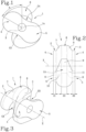
Figures 1, 2 and 3 are, respectively, a side view, a front view and a perspective view of a rotor with two lobes according to the invention; -
Figures 4, 5 and 6 are, respectively, a side view, a front view and a perspective view of a rotor with four lobes according to the invention; -
Figure 7 is a schematic side view of a volumetric pump for transporting liquids using two rotors with two lobes according to this invention; -
Figures 8 and 9 are front and perspective views illustrating a static coupling of the two rotors with two lobes located in the volumetric pump ofFigure 7 . - With reference to the accompanying drawings, and with particular reference to
Figures 1 to 6 , the drawings illustrate a lobe rotor, labelled 1 in its entirety, applicable to a volumetric pump, labelled 100 in its entirety, which is used for transporting liquids having solid particles inside it. By way of non-limiting example, they may be food liquids, such as, for example (but not necessarily), those typical of the wine sector. - As illustrated in
Figures 1 to 3 , therotor 1 comprises a first 2 and a second 3 section defining the respective ends of therotor 1; the twosections - Each first 2 and second 3 section has the same profile comprising at least two
lobes central hub 1a through which the axis X of the rotor passes. - The extension of the two
lobes rotor 1. - Again as illustrated, the first 2 and second 3 sections are positioned relative to each other with their respective profiles coinciding along the axis X the rotor.
- Again as illustrated, the
rotor 1 comprises a thirdcentral section 6 interposed between thefirst section 2 and thesecond section 3, along the axis X of the rotor. - The
third section 6 has the same profile as the first 2 and second 3 end sections, that is to say, comprising at least twolobes - Moreover, the
third section 6 is rotated, about the axis X of the rotor, with respect to the first 2 and second 3 sections in such a way as to offset by an angle α the respective vertices and grooves G4 and G5 of the at least twolobes lobes - Again as illustrated, the
rotor 1 comprises a first 7 and a second 8 joining body between the first 2 and the second 3 end sections and the thirdcentral section 6. - Each first 7 and second 8 joining body has inclined connecting surfaces, along the axis X of the rotor, for connecting the respective vertices and grooves G4 and G5 of the at least two
lobes surface 9 of the thirdcentral section 6, having the edges parallel to the axis X the rotor, and by twosurfaces surface 9 of the thirdcentral section 6. - In other words, the
rotor 1 is divided into two portions joined by a central section offset angularly relative to the end sections in such a way as to make two profiles of extension of the body of the rotor forming two inclined half-grooves, for each groove present on the rotor, joined by the vertex of the central section. The two half-grooves are therefore, in use, two half-chambers for sucking/discharging the liquid which are able to correctly balance the axial and radial forces during the operating steps of the rotor inside the volumetric pump. -
Figures 1 to 6 illustrate two different constructional configurations of the rotors: -
Figures 1 to 3 illustrate a rotor with two lobes; -
Figures 4 to 6 illustrate a rotor with four lobes. - The description refers in any case to the geometry of the lobes and of the rotors which are valid for all the configurations illustrated and also for configurations, for example, with three, five or six lobes, without limiting the scope of protection of this invention.
- It should be noted that each groove G4 and G5 of the
rotor 1 is formed, along the axis X of the rotor, byrespective surfaces 9 having the edges parallel to the axis X of the first 2, second 3 end sections and the thirdcentral section 6 and by the two inclined and convergingsurfaces surfaces 9 parallel to the axis X of the rotor so as to obtain a groove G4 and G5 with a trapezoidal configuration. - As illustrated, the third
central section 6 is rotated, about the axis X of the rotor, with respect to the first 2 and second 3 sections by an angle α less than 90°. - In light of this, the third
central section 6 is rotated, about the axis X of the rotor, with respect to the first 2 and second 3 sections by an angle α of between 30° and 60°. - The offset angle α of the third
central section 6 may vary as a function also of the number of lobes present on therotor 1. - As may be observed in the drawings, the
first end section 2 has a first thickness S1, calculated along the axis X of the rotor, equal to a second thickness S2 of thesecond section 2. - In light of this, the third
central section 6 has a third thickness S3, calculated along the axis X of the rotor, different from the first thickness S1 and from the second thickness S2. - According to this non-limiting solution, the third central section S3 has a third thickness S3 greater than the first S1 and the second S2 thicknesses of the first 2 and of the second 3 sections.
- The thickness of the third
central section 6 may vary as a function of the extension of the grooves G4 and G5 and in particular of the desired axial extension of the two half-grooves of each groove present. - This invention also provides a
volumetric pump 100 for transporting liquids comprising (seeFigures 7 to 9 ): - a
containment chamber 12 divided into afirst part 12a with a semi-circular profile and asecond part 12b with a semi-circular profile joined by a first 13 and a second 14 duct for flow of a liquid to be pumped; - a
first rotor 1 partly housed in the firstsemi-circular part 12a of thechamber 12 and having a first central axis X, a firstcentral hub 1a and at least a first pair oflobes first hub 1a; eachlobe hub 1a; - a second rotor 1' partly housed in the second
semi-circular part 12b of thechamber 12 and having a second central axis X', a secondcentral hub 1a' and at least a second pair of lobes 4', 5' spaced at equal angular intervals from each other on the periphery of thesecond hub 1a'; each lobe 4', 5' protrudes radially from thesecond hub 1 a'; - a
motion device 15 connected to the first 1 and second 1' rotor and configured to rotate the first 1 and second 1' rotor about the corresponding first X and second X' axis, in such a way as to obtain a rotational movement of the tworotors 1; 1' which is able to generate a passage of the fluid from the first 13 to the second 14 duct or vice versa through thechamber 12 and by a synchronised intersection of thelobes rotors 1, 1'. - The
volumetric pump 100 comprises thefirst rotor 1 and the second rotor 1' structured as described above. - This rotor structure according to the invention therefore fully achieves the preset aims.
- The advantages obtained with the structure of the rotors are as follows.
- A reduction in the pulsations during the rotations of the rotors in the pump at high speeds thanks to the "trapezoidal" geometry of the grooves which are substantially divided into two half-grooves which, in fact, in use in the pump and coordinated with the half-grooves of the other rotor define a sort of chamber divided into two parts with opposite geometry which is able to balance the flow of the fluid entering and flowing out.
- In effect, when the two rotors rotate inside the chamber the volumes for passage of the fluid (inlet and outlet) are variable in a progressive, constant and controlled fashion with a consequent reduction in flow of pulsating type and not constant inside the chamber.
- The same geometry with chambers with double inclined surface makes it possible to keep balanced the radial force and the axial force acting on the rotor in such a way as to reduce the vibrations of the pump and avoid having to apply axial locking components on the rotor.
Claims (6)
- A lobe rotor applicable to a volumetric pump for conveying liquids, said rotor (1) comprising:- a first (2) and a second (3) section defining the respective ends of the rotor (1), spaced apart from each other along a longitudinal axis (X) of extension of the rotor; each first (2) and second (3) section having the same profile comprising at least two lobes (4, 5) extending radially, with respect to a hub (1a) through which the central axis (X) the rotor passes and whose extension defines respective vertices and corresponding grooves (G4, G5) of the rotor (1); the first (2) and second (3) section being positioned relative to each other with their respective profiles coinciding along the axis (X) the rotor;- a third central section (6) interposed between the first (2) and the second section (3), along the axis (X) the rotor, and having the same profile as the first (2) and second (3) end section, that is to say, comprising at least two lobes (4, 5) with a radial extension whose extension defines respective vertices and corresponding grooves (G4, G5); the third section (6) being rotated about the axis (X) of the rotor, with respect to the first (2) and second (3) cross section in such a way as to offset by an angle (α) the respective vertices and grooves (G4, G5) of the at least two lobes (4, 5) with respect to the vertices and grooves (G4, G5) of the lobes (4, 5) of the first (2) and second (3) section;- a first (7) and a second (8) joining body between the first (2) and the second (3) end section and the third central section (6); each first (7) and second (8) joining body having inclined connecting surfaces, along the axis (X) of the rotor, for connecting the respective vertices and grooves (G4, G5) of the at least two lobes (4, 5) of the first (2), second (3) and third (6) central section so as to form at least two grooves (G4, G5) opposite each other, along an axis perpendicular to the axis (X) of the rotor, with undulating extension and each formed at least by a surface (9) of the third central section (6) having the edges parallel to the axis (X) the rotor and by two surfaces (10, 11) formed respectively by the first (7) and second (8) joining body and having the edges inclined and converging towards the central surface (9), characterised in that the first end section (2) has a first thickness (S1), calculated along the axis (X) of the rotor, equal to a second thickness (S2) presented by the second section (2), the third central section (6) having a third thickness (S3), calculated along the axis (X) of the rotor, different from the first (S1) and second (S2) thickness.
- The rotor according to claim 1, wherein each groove (G4, G5) of the rotor (1) is formed along the axis (X) of the rotor, by respective surfaces (9) having the edges parallel to the axis (X) of the first (2), second (3) end section and the third central section (6) and by the two inclined and converging surfaces (10, 11) of the first (2) and second (3) body joining the three surfaces (9) parallel to the axis (X) of the rotor so as to obtain a groove (G4, G5) with a trapezoidal configuration.
- The rotor according to claim 1 or 2, wherein the third section (6) is rotated, about the axis (X) of the rotor, with respect to the first (2) and second (3) section by an angle (α) less than 90°.
- The rotor according to claim 1 or 2, wherein the third section (6) is rotated, about the axis (X) of the rotor, with respect to the first (2) and second (3) section by an angle (α) of between 30° and 60°.
- The rotor according to claim 1, wherein the third central section (S3) has a third thickness (S3) greater than the first (S1) and the second (S2) thickness of the first (2) and of the second (3) section.
- A volumetric pump for conveying liquids comprising:- a containment chamber (12) divided into a first part (12a) with a semi-circular profile and a second part (12b) with a semi-circular profile joined by a first (13) and a second (14) duct for flow of a liquid to be pumped;- a first rotor (1) partly housed in the first semi-circular part (12a) of the chamber (12) and having a first central axis (X), a first central hub (1a) and at least a first pair of lobes (4, 5) spaced at equal angular intervals from each other on the periphery of the first hub (1a); each lobe (4, 5) protruding radially from the hub (1a);- a second rotor (1') partly housed in the second semi-circular part (12b) of the chamber (12) and having a second central axis (X'), a second central hub (1a') and at least a second pair of lobes (4', 5') spaced at equal angular intervals from each other on the periphery of the second hub (1a'); each lobe (4', 5') protruding radially from the second hub (1a');- a motion device (15) connected to the first (1) and second (1') rotor and configured to rotate the first (1) and second (1') rotor about the corresponding first (X) and second (X') axis, in such a way as to obtain a rotational movement of the two rotors (1; 1') which is able to generate a passage of the fluid from the first (13) to the second (14) duct or vice versa through the chamber (12) and by a synchronised intersection of the lobes (4, 5, 4', 5') of the two rotors (1, 1'); characterised in that it comprises the first (1) and the second (1') rotor structured according to any one of claims 1 to 5.
Applications Claiming Priority (1)
| Application Number | Priority Date | Filing Date | Title |
|---|---|---|---|
| IT202300007485 | 2023-04-18 |
Publications (3)
| Publication Number | Publication Date |
|---|---|
| EP4450815A1 true EP4450815A1 (en) | 2024-10-23 |
| EP4450815C0 EP4450815C0 (en) | 2026-02-11 |
| EP4450815B1 EP4450815B1 (en) | 2026-02-11 |
Family
ID=87514277
Family Applications (1)
| Application Number | Title | Priority Date | Filing Date |
|---|---|---|---|
| EP24169898.4A Active EP4450815B1 (en) | 2023-04-18 | 2024-04-12 | Lobe rotor for a volumetric pump |
Country Status (1)
| Country | Link |
|---|---|
| EP (1) | EP4450815B1 (en) |
Citations (4)
| Publication number | Priority date | Publication date | Assignee | Title |
|---|---|---|---|---|
| US5415041A (en) | 1994-01-24 | 1995-05-16 | Flowdata, Inc. | Double helical flowmeter |
| CN106837784A (en) | 2017-04-07 | 2017-06-13 | 夏三华 | It is a kind of to be suitable to the gear pump that the whole network distribution transmission & distribution heating system is used |
| EP3272999A1 (en) | 2016-07-20 | 2018-01-24 | Settima Meccanica Srl - Societa a Socio Unico | Bi-helical toothed wheel with variable helix angle and non-encapsulating tooth profile for hydraulic gear apparatuses |
| EP3623774A1 (en) | 2018-09-11 | 2020-03-18 | Common Spolka Akcyjna | Rotary flow meter for measuring gas flow |
-
2024
- 2024-04-12 EP EP24169898.4A patent/EP4450815B1/en active Active
Patent Citations (4)
| Publication number | Priority date | Publication date | Assignee | Title |
|---|---|---|---|---|
| US5415041A (en) | 1994-01-24 | 1995-05-16 | Flowdata, Inc. | Double helical flowmeter |
| EP3272999A1 (en) | 2016-07-20 | 2018-01-24 | Settima Meccanica Srl - Societa a Socio Unico | Bi-helical toothed wheel with variable helix angle and non-encapsulating tooth profile for hydraulic gear apparatuses |
| CN106837784A (en) | 2017-04-07 | 2017-06-13 | 夏三华 | It is a kind of to be suitable to the gear pump that the whole network distribution transmission & distribution heating system is used |
| EP3623774A1 (en) | 2018-09-11 | 2020-03-18 | Common Spolka Akcyjna | Rotary flow meter for measuring gas flow |
Also Published As
| Publication number | Publication date |
|---|---|
| EP4450815C0 (en) | 2026-02-11 |
| EP4450815B1 (en) | 2026-02-11 |
Similar Documents
| Publication | Publication Date | Title |
|---|---|---|
| US11506056B2 (en) | Rotary machine | |
| US3512904A (en) | Progressing cavity helical pump | |
| US7479000B2 (en) | Gear pump | |
| US11608827B2 (en) | Helical trochoidal rotary machines with offset | |
| US8556607B2 (en) | Screw rotor | |
| US12473912B2 (en) | Axial load in helical trochoidal rotary machines | |
| EP0702154B1 (en) | Roller gerotor device | |
| US9777729B2 (en) | Dual axis rotor | |
| US20080031760A1 (en) | Gerotor pump | |
| EP4450815B1 (en) | Lobe rotor for a volumetric pump | |
| US9752571B2 (en) | Multiple segment lobe pump | |
| CN106609753B (en) | Merge gerotor pump and motor | |
| CN102301140B (en) | Positive displacement pump with impeller and manufacturing method thereof | |
| US20140161655A1 (en) | Pump | |
| US5613846A (en) | Filling, fluid-transporting, and pumping device | |
| US5069606A (en) | Rotary fluid displacement apparatus | |
| CA2626288A1 (en) | Rotor for a rotary machine and a rotary machine | |
| US3240155A (en) | Helical rotary pumps | |
| EA028571B1 (en) | Working member of a helical rotary machine | |
| US12012962B2 (en) | Fluid transfer device | |
| KR0183366B1 (en) | Spairal pump | |
| CN210265111U (en) | Single rotor displacement pump | |
| CN120626444A (en) | A balanced low-vibration medium conveying system | |
| JP2002310083A (en) | Uniaxial axial flow type fluid machine | |
| EP3827172A1 (en) | Volumetric pump with flow complementary radial cams |
Legal Events
| Date | Code | Title | Description |
|---|---|---|---|
| PUAI | Public reference made under article 153(3) epc to a published international application that has entered the european phase |
Free format text: ORIGINAL CODE: 0009012 |
|
| STAA | Information on the status of an ep patent application or granted ep patent |
Free format text: STATUS: THE APPLICATION HAS BEEN PUBLISHED |
|
| AK | Designated contracting states |
Kind code of ref document: A1 Designated state(s): AL AT BE BG CH CY CZ DE DK EE ES FI FR GB GR HR HU IE IS IT LI LT LU LV MC ME MK MT NL NO PL PT RO RS SE SI SK SM TR |
|
| STAA | Information on the status of an ep patent application or granted ep patent |
Free format text: STATUS: REQUEST FOR EXAMINATION WAS MADE |
|
| 17P | Request for examination filed |
Effective date: 20250422 |
|
| RIC1 | Information provided on ipc code assigned before grant |
Ipc: F04C 2/08 20060101AFI20250630BHEP Ipc: F04C 2/12 20060101ALI20250630BHEP Ipc: F04C 13/00 20060101ALI20250630BHEP |
|
| GRAP | Despatch of communication of intention to grant a patent |
Free format text: ORIGINAL CODE: EPIDOSNIGR1 |
|
| STAA | Information on the status of an ep patent application or granted ep patent |
Free format text: STATUS: GRANT OF PATENT IS INTENDED |
|
| INTG | Intention to grant announced |
Effective date: 20250905 |
|
| GRAS | Grant fee paid |
Free format text: ORIGINAL CODE: EPIDOSNIGR3 |
|
| GRAA | (expected) grant |
Free format text: ORIGINAL CODE: 0009210 |
|
| STAA | Information on the status of an ep patent application or granted ep patent |
Free format text: STATUS: THE PATENT HAS BEEN GRANTED |
|
| AK | Designated contracting states |
Kind code of ref document: B1 Designated state(s): AL AT BE BG CH CY CZ DE DK EE ES FI FR GB GR HR HU IE IS IT LI LT LU LV MC ME MK MT NL NO PL PT RO RS SE SI SK SM TR |
|
| REG | Reference to a national code |
Ref country code: CH Ref legal event code: F10 Free format text: ST27 STATUS EVENT CODE: U-0-0-F10-F00 (AS PROVIDED BY THE NATIONAL OFFICE) Effective date: 20260211 Ref country code: GB Ref legal event code: FG4D |
|
| REG | Reference to a national code |
Ref country code: DE Ref legal event code: R096 Ref document number: 602024002461 Country of ref document: DE |
|
| REG | Reference to a national code |
Ref country code: IE Ref legal event code: FG4D |
|
| U01 | Request for unitary effect filed |
Effective date: 20260304 |
|
| U07 | Unitary effect registered |
Designated state(s): AT BE BG DE DK EE FI FR IT LT LU LV MT NL PT RO SE SI Effective date: 20260330 |