EP3623774A1 - Rotary flow meter for measuring gas flow - Google Patents
Rotary flow meter for measuring gas flow Download PDFInfo
- Publication number
- EP3623774A1 EP3623774A1 EP18193611.3A EP18193611A EP3623774A1 EP 3623774 A1 EP3623774 A1 EP 3623774A1 EP 18193611 A EP18193611 A EP 18193611A EP 3623774 A1 EP3623774 A1 EP 3623774A1
- Authority
- EP
- European Patent Office
- Prior art keywords
- rotors
- flow meter
- rotor
- teeth
- tops
- Prior art date
- Legal status (The legal status is an assumption and is not a legal conclusion. Google has not performed a legal analysis and makes no representation as to the accuracy of the status listed.)
- Granted
Links
Images


Classifications
-
- G—PHYSICS
- G01—MEASURING; TESTING
- G01F—MEASURING VOLUME, VOLUME FLOW, MASS FLOW OR LIQUID LEVEL; METERING BY VOLUME
- G01F3/00—Measuring the volume flow of fluids or fluent solid material wherein the fluid passes through the meter in successive and more or less isolated quantities, the meter being driven by the flow
- G01F3/02—Measuring the volume flow of fluids or fluent solid material wherein the fluid passes through the meter in successive and more or less isolated quantities, the meter being driven by the flow with measuring chambers which expand or contract during measurement
- G01F3/04—Measuring the volume flow of fluids or fluent solid material wherein the fluid passes through the meter in successive and more or less isolated quantities, the meter being driven by the flow with measuring chambers which expand or contract during measurement having rigid movable walls
- G01F3/06—Measuring the volume flow of fluids or fluent solid material wherein the fluid passes through the meter in successive and more or less isolated quantities, the meter being driven by the flow with measuring chambers which expand or contract during measurement having rigid movable walls comprising members rotating in a fluid-tight or substantially fluid-tight manner in a housing
- G01F3/10—Geared or lobed impeller meters
Definitions
- the present invention relates to a rotary flow meter for measuring gas flow
- the invention represents the field of measuring instruments that register the volume of flowing gas.
- Rotary flow meters are characterised by pulsed gas flow. Pulsation is transferred in the form of vibrations to other elements of the unit and may interfere with their operation. There are two main reasons why pulsation is generated. The first is related to the closing and opening of measurement chambers, whereby gas with a higher pressure at the inlet to the inside of the body of the flow meter is transported towards the lower pressure at the outlet from the inside of the body of the flow meter and a pressure surge occurs at the outlet side.
- the second type of pulsation is produced by uneven increment of volume and pressure in the spaces between the teeth of the rotors, depending on the angle of their rotation. The nature of volume changes depends for example on the shape and profile of the rotors used.
- Document US5415041A discloses a device for flow measurement, with two dual helically curved rotors.
- the four-toothed rotors described in the American patent application rotate in mutual contact, thereby providing a high contact factor.
- the solution allows for limiting the generation of axial, lateral and distal loads between the rotors and as a result of changes of pressure in the measurement device.
- the object of the invention is to overcome the drawbacks of the prior art solutions and to completely eliminate pulsation in the flow meter due to uneven increment of volume between the teeth of the rotors.
- the essence of the solution is a rotary flow meter for measuring gas flow, comprising a pair of three-toothed rotors, each of which has the shape of a double helical gear, wherein the first rotor is a mirror reflection of the second rotor, and the rotors are adapted to rotate in opposite directions; moreover, the flow meter comprises a body sealing the rotors, adapted to form temporary measurement chambers having a strictly defined volume, formed between the outer surfaces of the rotors and the inner surface of the body.
- the rotary flow meter according to the invention is characterised by the rotors adapted not to contact each other and which are synchronised via an external module synchronising the rotation of the rotors.
- the flow meter is characterised by the adjacent teeth of the three-toothed rotors (2,3) in the shape of a H-bone gear having their tops displaced from each other by an angle(Y) of 120°.
- the flow meter is characterised by the displacement angle ( ⁇ ) of the tops of the tooth of the rotor along the height of the rotor corresponding to half the displacement angle(Y) of the tops of adjacent teeth of the rotor with respect to each other.
- the flow meter is characterised by the rotors and the body of the flow meter being made of plastic in 3D printing technology.
- the flow meter is characterised by the rotors and the body of the flow meter being made of an electrically conductive plastic.
- the solution of the invention is advantageous because of the complete elimination of pulsation resulting from uneven increments of volume and pressure between the teeth of the rotors achieved through the use of an external synchronising module that prevents the rotors from contacting each other. Additionally, the use of three-toothed rotors in the shape of a double helical gear with a specific displacement angle of the rotors' tops with respect to each other and a specific wrap ang le, an internal balance of axial forces between the rotors has been achieved.
- FIG. 1 is a schematic view of the rotary flow meter 1 in an embodiment, in a top view.
- the rotary flow meter 1 has a pair of three-toothed rotors 2, 3, adapted by an external synchronising module 11 (not shown in Fig. 1 ) to rotate in opposite directions.
- the rotors 2, 3 are arranged in the body 4 sealing the rotors 2, 3 adapted to form temporary measurement chambers 5, 6 such that the inner surface of the body 7 cooperates with the individual rotors 2, 3 over a section having an angular length expressed by the wrap angle ( ⁇ ).
- the wrap angle ( ⁇ ) is 180°
- the adjacent teeth of the three-toothed rotors 2, 3 in the shape of a double helical gear have their tops displaced from each other by an angle (Y) of 120°.
- body 4 is adapted to form temporary measurement chambers 5, 6 having a strictly defined volume, such that gas flowing to the inside of the body 4 through the inlet 8 fills the measurement chambers 5, 6 formed between the external surfaces of the rotors 9 and the internal surface of the body 7, and the overpressure at the inlet 8 of the gas causes the rotors 2, 3 to rotate and a portion of gas to be transported to the outlet from the inside of the body 4.
- the rotors (2, 3) and the body (4) of the flow meter can be made of plastic in 3D printing technology, and preferably, in particular of an electrically conductive plastic.
- the advantage achieved by using the 3D printing technology when making the flow meters is the ability to precisely and accurately reproduce the shape of the rotors.
- the use of an electrically conductive plastic is important as it regards safety and it allows for discharging the electrostatic charge accumulating in the flowing gas.
- Fig. 2 is a view of two rotors 2, 3 in the shape of a double helical gear coupled with an external synchronising module 11 in an isometric view.
- the first rotor 2 is a mirror reflection of the second rotor 3, and, in addition, the rotors 2, 3 are adapted by an external synchronising module 11 to rotate in the opposite direction, without contacting each other, and, preferably, the second rotor 3 is adapted to rotate clockwise, and the first rotor 2 is adapted to rotate counter-clockwise.
- the synchronising module 11 synchronises the rotations of the rotors 2, 3 so that the surfaces of the rotors 2, 3 do not contact each other.
- the synchronising module preferably has the form of a gear transmission with two interlocking toothed wheels 12.
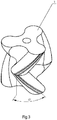
- Fig. 3 is a detailed view of the rotor 3 of the rotary flow meter 1.
- An advantageous technical result of balancing the axial forces between the rotors 2, 3 has been achieved by using an appropriate profile and shape thereof, in particular by selecting an appropriate displacement angle ( ⁇ ) of the tops of the individual teeth of the rotors 2, 3.
- the advantageous result of balancing the axial forces is achieved when the displacement angle ( ⁇ ) of the tops of the tooth of the rotor 3 in relation to the height of the rotor 3 corresponds to half the angle (Y) between adjacent tops of the rotor 3.
- angle ( ⁇ ) has 60°.
Landscapes
- Physics & Mathematics (AREA)
- Fluid Mechanics (AREA)
- General Physics & Mathematics (AREA)
- Measuring Volume Flow (AREA)
Abstract
Description
- The invention represents the field of measuring instruments that register the volume of flowing gas. Rotary flow meters are characterised by pulsed gas flow. Pulsation is transferred in the form of vibrations to other elements of the unit and may interfere with their operation. There are two main reasons why pulsation is generated. The first is related to the closing and opening of measurement chambers, whereby gas with a higher pressure at the inlet to the inside of the body of the flow meter is transported towards the lower pressure at the outlet from the inside of the body of the flow meter and a pressure surge occurs at the outlet side. The second type of pulsation is produced by uneven increment of volume and pressure in the spaces between the teeth of the rotors, depending on the angle of their rotation. The nature of volume changes depends for example on the shape and profile of the rotors used.
- Document
US4329130A discloses a rotary flow meter in which three-toothed rotors have a single curved profile, wherein both rotors have the same profile, the same size and the same twist ratio. In the solution disclosed in the American application, the profiles of the rotors are contacted during rotation, and the phenomenon of pulsation is slightly limited by reducing the mutual pressure of the rotor surfaces and the energy transfer between the rotors. - Document
US5415041A discloses a device for flow measurement, with two dual helically curved rotors. The four-toothed rotors described in the American patent application rotate in mutual contact, thereby providing a high contact factor. The solution allows for limiting the generation of axial, lateral and distal loads between the rotors and as a result of changes of pressure in the measurement device. - The object of the invention is to overcome the drawbacks of the prior art solutions and to completely eliminate pulsation in the flow meter due to uneven increment of volume between the teeth of the rotors.
- The essence of the solution is a rotary flow meter for measuring gas flow, comprising a pair of three-toothed rotors, each of which has the shape of a double helical gear, wherein the first rotor is a mirror reflection of the second rotor, and the rotors are adapted to rotate in opposite directions; moreover, the flow meter comprises a body sealing the rotors, adapted to form temporary measurement chambers having a strictly defined volume, formed between the outer surfaces of the rotors and the inner surface of the body. The rotary flow meter according to the invention is characterised by the rotors adapted not to contact each other and which are synchronised via an external module synchronising the rotation of the rotors.
- Preferably, the flow meter is characterised by the teeth of the rotors in the shape of a double helical gear having their tops displaced along the height of the rotor by an angle (α)

- Preferably, the flow meter is characterised by three-toothed rotors in the shape of a double helical gear interacting with the inner surface of the body over a section with an angular length expressed by the wrap angle (β)

- Preferably, the flow meter is characterised by the adjacent teeth of the three-toothed rotors (2,3) in the shape of a H-bone gear having their tops displaced from each other by an angle(Y) of 120°.
- Preferably, the flow meter is characterised by the displacement angle (α) of the tops of the tooth of the rotor along the height of the rotor corresponding to half the displacement angle(Y) of the tops of adjacent teeth of the rotor with respect to each other.
- Preferably, the flow meter is characterised by the rotors and the body of the flow meter being made of plastic in 3D printing technology.
- Preferably, the flow meter is characterised by the rotors and the body of the flow meter being made of an electrically conductive plastic.
- The solution of the invention is advantageous because of the complete elimination of pulsation resulting from uneven increments of volume and pressure between the teeth of the rotors achieved through the use of an external synchronising module that prevents the rotors from contacting each other. Additionally, the use of three-toothed rotors in the shape of a double helical gear with a specific displacement angle of the rotors' tops with respect to each other and a specific wrap ang le, an internal balance of axial forces between the rotors has been achieved.
- The subject matter of the invention is presented in greater detail in a preferred embodiment in the drawing, in which:
-
Fig. 1 is a schematic view of the rotary flow meter in a top view; -
Fig. 2 is a view of two rotors coupled with an external synchronising module, in an isometric view; -
Fig. 3 is a detailed view of the rotor of the rotary flow meter; - In
fig. 1 is a schematic view of therotary flow meter 1 in an embodiment, in a top view. Therotary flow meter 1 has a pair of three-toothed rotors Fig. 1 ) to rotate in opposite directions. Therotors body 4 sealing therotors temporary measurement chambers body 7 cooperates with theindividual rotors 
- According to this embodiment of the
rotary flow meter 1 with three-toothed rotors toothed rotors rotors body 4 is adapted to formtemporary measurement chambers body 4 through theinlet 8 fills themeasurement chambers rotors 9 and the internal surface of thebody 7, and the overpressure at theinlet 8 of the gas causes therotors body 4. The rotors (2, 3) and the body (4) of the flow meter can be made of plastic in 3D printing technology, and preferably, in particular of an electrically conductive plastic. The advantage achieved by using the 3D printing technology when making the flow meters is the ability to precisely and accurately reproduce the shape of the rotors. The use of an electrically conductive plastic is important as it regards safety and it allows for discharging the electrostatic charge accumulating in the flowing gas. -
Fig. 2 is a view of tworotors external synchronising module 11 in an isometric view. According to this embodiment of the invention, thefirst rotor 2 is a mirror reflection of thesecond rotor 3, and, in addition, therotors external synchronising module 11 to rotate in the opposite direction, without contacting each other, and, preferably, thesecond rotor 3 is adapted to rotate clockwise, and thefirst rotor 2 is adapted to rotate counter-clockwise. Moreover, thesynchronising module 11 synchronises the rotations of therotors rotors fig. 2 the synchronising module preferably has the form of a gear transmission with two interlockingtoothed wheels 12. -
Fig. 3 is a detailed view of therotor 3 of therotary flow meter 1. An advantageous technical result of balancing the axial forces between therotors rotors rotor 3 in relation to the height of therotor 3 corresponds to half the angle (Y) between adjacent tops of therotor 3. Moreover, angle (α) depends directly on the number of teeth of the rotor (z) and can be calculated based on the following ratio
- According to this embodiment of the three-toothed rotor, angle (α) has 60°.
Claims (7)
- Rotary flow meter (1) for measuring gas flow comprisinga pair of three-toothed rotors (2, 3), each of which has the shape of a double helical gear, wherein the first rotor (2) is a mirror reflection of the second rotor (3), and the rotors (2, 3) are adapted to rotate in opposite directions; moreover, the flow meter comprisesa body (4) sealing the rotors (2, 3), adapted to form temporary measurement chambers having a strictly defined volume, formed between the outer surfaces of the rotors (9) and the inner surface of the body (7).characterised in thatthe rotors (2, 3) are adapted not to contact each other and which are synchronised via an external module synchronising (11) the rotation of the rotors (2, 3).
- The flow meter according to claim 1 characterised in that the teeth of the rotors (2, 3) in the shape of a double helical gear have their tops displaced along the height of the rotor by an angle (α)

- The flow meter according to claim 1 or 2 characterised in that three-toothed rotors (2, 3) in the shape of a double helical gear interact with the inner surface of the body (7) over a section with an angular length expressed by the wrap angle (β)

- The flow meter according to any of the claims 1 to 3, characterised in that the adjacent teeth of the three-toothed rotors (2,3) in the shape of a H-bone gear have their tops displaced from each other by an angle (Y) of 120°.
- The flow meter according to claim 2 or 4, characterised in that the displacement angle (α) of the tops of the tooth of the rotor along the height of the rotor corresponds to half the displacement angle (Y) of the tops of adjacent teeth of the rotor with respect to each other.
- The flow meter according to any of the claims 1 to 5, characterised in that the rotors (2, 3) and the body (4) of the flow meter being made of plastic in 3D printing technology.
- The flow meter according to any of the claims 1 to 6, characterised in that the rotors (2, 3) and the body (4) of the flow meter being made of an electrically conductive plastic.
Priority Applications (10)
| Application Number | Priority Date | Filing Date | Title |
|---|---|---|---|
| HUE18193611A HUE055648T2 (en) | 2018-09-11 | 2018-09-11 | Rotary flow meter for measuring gas flow |
| ES18193611T ES2883556T3 (en) | 2018-09-11 | 2018-09-11 | Rotary flow meter to measure gas flow |
| PL18193611T PL3623774T3 (en) | 2018-09-11 | 2018-09-11 | Rotary flow meter for measuring gas flow |
| EP18193611.3A EP3623774B1 (en) | 2018-09-11 | 2018-09-11 | Rotary flow meter for measuring gas flow |
| PT181936113T PT3623774T (en) | 2018-09-11 | 2018-09-11 | ROTARY FLOW METER FOR GAS FLOW MEASUREMENT |
| CN201980057044.9A CN112639414A (en) | 2018-09-11 | 2019-09-11 | Rotary flowmeter for measuring gas flow |
| CA3108617A CA3108617C (en) | 2018-09-11 | 2019-09-11 | Rotary flow meter for measuring gas flow |
| US17/263,331 US20210190565A1 (en) | 2018-09-11 | 2019-09-11 | Rotary Flow Meter For Measuring Gas Flow |
| PCT/EP2019/074275 WO2020053305A1 (en) | 2018-09-11 | 2019-09-11 | Rotary flow meter for measuring gas flow |
| KR1020217005253A KR102890737B1 (en) | 2018-09-11 | 2019-09-11 | Rotary flow meter for measuring gas flow rate |
Applications Claiming Priority (1)
| Application Number | Priority Date | Filing Date | Title |
|---|---|---|---|
| EP18193611.3A EP3623774B1 (en) | 2018-09-11 | 2018-09-11 | Rotary flow meter for measuring gas flow |
Publications (2)
| Publication Number | Publication Date |
|---|---|
| EP3623774A1 true EP3623774A1 (en) | 2020-03-18 |
| EP3623774B1 EP3623774B1 (en) | 2021-05-26 |
Family
ID=64051292
Family Applications (1)
| Application Number | Title | Priority Date | Filing Date |
|---|---|---|---|
| EP18193611.3A Active EP3623774B1 (en) | 2018-09-11 | 2018-09-11 | Rotary flow meter for measuring gas flow |
Country Status (10)
| Country | Link |
|---|---|
| US (1) | US20210190565A1 (en) |
| EP (1) | EP3623774B1 (en) |
| KR (1) | KR102890737B1 (en) |
| CN (1) | CN112639414A (en) |
| CA (1) | CA3108617C (en) |
| ES (1) | ES2883556T3 (en) |
| HU (1) | HUE055648T2 (en) |
| PL (1) | PL3623774T3 (en) |
| PT (1) | PT3623774T (en) |
| WO (1) | WO2020053305A1 (en) |
Cited By (1)
| Publication number | Priority date | Publication date | Assignee | Title |
|---|---|---|---|---|
| EP4450815A1 (en) | 2023-04-18 | 2024-10-23 | Roberto Manzini | Lobe rotor for a volumetric pump |
Citations (8)
| Publication number | Priority date | Publication date | Assignee | Title |
|---|---|---|---|---|
| US4224015A (en) * | 1977-01-19 | 1980-09-23 | Oval Engineering Co., Ltd. | Positive displacement flow meter with helical-toothed rotors |
| US4329130A (en) | 1978-07-03 | 1982-05-11 | Oval Engineering Company Limited | Flow meter with helical toothed rotors having no pulsation and zero contact pressure |
| US5415041A (en) | 1994-01-24 | 1995-05-16 | Flowdata, Inc. | Double helical flowmeter |
| US20100307234A1 (en) * | 2008-03-03 | 2010-12-09 | Oval Corporation | Positive displacement flowmeter and helical gear |
| US8082784B2 (en) * | 2008-06-16 | 2011-12-27 | Romet Limited | Rotary meter flexible edge impeller assembly |
| WO2015183135A1 (en) * | 2014-05-28 | 2015-12-03 | Закрытое Акционерное Общество "Технология Маркет" | Gear machine |
| US20160153819A1 (en) * | 2013-06-26 | 2016-06-02 | Robert Bosch Gmbh | Sensor device for detecting at least one property of a fluid medium flowing in a channel |
| RU2660701C1 (en) * | 2017-10-04 | 2018-07-09 | Леонид Григорьевич Кузнецов | Rotary supercharger |
Family Cites Families (16)
| Publication number | Priority date | Publication date | Assignee | Title |
|---|---|---|---|---|
| US2014932A (en) * | 1933-03-17 | 1935-09-17 | Gen Motors Corp | Roots blower |
| US2843094A (en) * | 1956-06-01 | 1958-07-15 | Brodie Ralph N Co | Positive displacement type fluid meter |
| DE3321718A1 (en) * | 1983-06-16 | 1984-12-20 | Arthur Pfeiffer Vakuumtechnik Wetzlar Gmbh, 6334 Asslar | ROLLING PISTON PUMP |
| JP3133748B2 (en) * | 1989-12-13 | 2001-02-13 | ハー.クルヘル ヴァルデマル | Volumetric type rotary turbine |
| CN1132002C (en) * | 1996-01-02 | 2003-12-24 | 株式会社椭圆 | Positive displacement flowmeter |
| CN1373297A (en) * | 2002-04-08 | 2002-10-09 | 华中科技大学 | Rotor of rotary piston type pump |
| CN101042301A (en) * | 2006-03-23 | 2007-09-26 | 上海一诺仪表有限公司 | 3-teeth double-rotor flowmeter |
| JP4254967B2 (en) * | 2006-05-17 | 2009-04-15 | 株式会社オーバル | Servo type volumetric flow meter |
| KR20140032990A (en) * | 2011-01-05 | 2014-03-17 | 노엠 레빈 | Flow meter |
| NL2005995C2 (en) * | 2011-01-12 | 2012-07-16 | Flow Meter Group B V | ROTOR METER FOR MEASURING A QUANTITY OF GAS. |
| JP5494521B2 (en) * | 2011-02-09 | 2014-05-14 | 株式会社タツノ | Capacity type flow meter |
| JP2012207660A (en) * | 2011-03-11 | 2012-10-25 | Toyota Industries Corp | Screw pump |
| DE102012009103A1 (en) * | 2012-05-08 | 2013-11-14 | Ralf Steffens | spindle compressor |
| US9470228B2 (en) * | 2012-07-03 | 2016-10-18 | Brian J. O'Connor | Multiple segment lobe pump |
| CN205642491U (en) * | 2016-05-11 | 2016-10-12 | 浙江裕顺仪表有限公司 | A Helical Rotor Type Gas Roots Flowmeter |
| JP7352387B2 (en) * | 2019-06-18 | 2023-09-28 | ベック株式会社 | Aqueous dressing composition |
-
2018
- 2018-09-11 HU HUE18193611A patent/HUE055648T2/en unknown
- 2018-09-11 EP EP18193611.3A patent/EP3623774B1/en active Active
- 2018-09-11 ES ES18193611T patent/ES2883556T3/en active Active
- 2018-09-11 PT PT181936113T patent/PT3623774T/en unknown
- 2018-09-11 PL PL18193611T patent/PL3623774T3/en unknown
-
2019
- 2019-09-11 CA CA3108617A patent/CA3108617C/en active Active
- 2019-09-11 KR KR1020217005253A patent/KR102890737B1/en active Active
- 2019-09-11 WO PCT/EP2019/074275 patent/WO2020053305A1/en not_active Ceased
- 2019-09-11 US US17/263,331 patent/US20210190565A1/en not_active Abandoned
- 2019-09-11 CN CN201980057044.9A patent/CN112639414A/en active Pending
Patent Citations (8)
| Publication number | Priority date | Publication date | Assignee | Title |
|---|---|---|---|---|
| US4224015A (en) * | 1977-01-19 | 1980-09-23 | Oval Engineering Co., Ltd. | Positive displacement flow meter with helical-toothed rotors |
| US4329130A (en) | 1978-07-03 | 1982-05-11 | Oval Engineering Company Limited | Flow meter with helical toothed rotors having no pulsation and zero contact pressure |
| US5415041A (en) | 1994-01-24 | 1995-05-16 | Flowdata, Inc. | Double helical flowmeter |
| US20100307234A1 (en) * | 2008-03-03 | 2010-12-09 | Oval Corporation | Positive displacement flowmeter and helical gear |
| US8082784B2 (en) * | 2008-06-16 | 2011-12-27 | Romet Limited | Rotary meter flexible edge impeller assembly |
| US20160153819A1 (en) * | 2013-06-26 | 2016-06-02 | Robert Bosch Gmbh | Sensor device for detecting at least one property of a fluid medium flowing in a channel |
| WO2015183135A1 (en) * | 2014-05-28 | 2015-12-03 | Закрытое Акционерное Общество "Технология Маркет" | Gear machine |
| RU2660701C1 (en) * | 2017-10-04 | 2018-07-09 | Леонид Григорьевич Кузнецов | Rotary supercharger |
Cited By (1)
| Publication number | Priority date | Publication date | Assignee | Title |
|---|---|---|---|---|
| EP4450815A1 (en) | 2023-04-18 | 2024-10-23 | Roberto Manzini | Lobe rotor for a volumetric pump |
Also Published As
| Publication number | Publication date |
|---|---|
| EP3623774B1 (en) | 2021-05-26 |
| CA3108617A1 (en) | 2020-03-19 |
| WO2020053305A1 (en) | 2020-03-19 |
| PT3623774T (en) | 2021-07-23 |
| US20210190565A1 (en) | 2021-06-24 |
| CA3108617C (en) | 2023-07-18 |
| KR20210054508A (en) | 2021-05-13 |
| KR102890737B1 (en) | 2025-11-24 |
| PL3623774T3 (en) | 2021-11-22 |
| HUE055648T2 (en) | 2021-12-28 |
| ES2883556T3 (en) | 2021-12-09 |
| CN112639414A (en) | 2021-04-09 |
Similar Documents
| Publication | Publication Date | Title |
|---|---|---|
| JP4252614B1 (en) | Volumetric flow meter and helical gear | |
| Wang et al. | Geometric study and simulation of an elliptical rotor profile for Roots vacuum pumps | |
| EP3623774B1 (en) | Rotary flow meter for measuring gas flow | |
| GB1597011A (en) | Rotary positive displacement flow meter | |
| ITPR20090042A1 (en) | SCREW COMPRESSOR | |
| US20030175141A1 (en) | Wave tooth gears using identical non-circular conjugating pitch curves | |
| Tien et al. | A novel design of the Roots blower | |
| JPH1089443A (en) | Elliptic gear | |
| ITBO20000119A1 (en) | VOLUMETRIC ROTARY PUMP WITH HELICAL ROTORS. | |
| CN116480581B (en) | A screw assembly and a vacuum pump | |
| KR100556014B1 (en) | Non circular gear and positive displacement flowmeter using it | |
| Lacevic et al. | On Rotor Profling of Internally Geared Screw Machines | |
| CN101925803B (en) | Positive displacement flowmeter | |
| Karamooz Ravari | Elliptical lobe shape gerotor pump design to minimize wear | |
| EP2551649A1 (en) | Improved positive displacement flow meter | |
| KR101488277B1 (en) | Volume type flow meter | |
| CN1132002C (en) | Positive displacement flowmeter | |
| EP2098684A2 (en) | Positive-displacement machine design (variants) | |
| AU2012100424B4 (en) | Positive displacement tri-gear flowmeter | |
| Yang et al. | Flowrate formulation and displacement analyses for deviation function-based gerotor pumps | |
| Dong et al. | Elastic kinematic and geometric model of harmonic gear drives | |
| CN102928035B (en) | Volumetric flow meter provided with multiple layers of scraper plate measuring elements | |
| CN201548265U (en) | A Floating Internal Gear Type Low Pulsation Gear Flowmeter | |
| JPS6347618A (en) | Fluid machine rotor by uneven tooth type spur gear | |
| JPS60182379A (en) | Noncircular rotor |
Legal Events
| Date | Code | Title | Description |
|---|---|---|---|
| PUAI | Public reference made under article 153(3) epc to a published international application that has entered the european phase |
Free format text: ORIGINAL CODE: 0009012 |
|
| STAA | Information on the status of an ep patent application or granted ep patent |
Free format text: STATUS: THE APPLICATION HAS BEEN PUBLISHED |
|
| AK | Designated contracting states |
Kind code of ref document: A1 Designated state(s): AL AT BE BG CH CY CZ DE DK EE ES FI FR GB GR HR HU IE IS IT LI LT LU LV MC MK MT NL NO PL PT RO RS SE SI SK SM TR |
|
| AX | Request for extension of the european patent |
Extension state: BA ME |
|
| STAA | Information on the status of an ep patent application or granted ep patent |
Free format text: STATUS: REQUEST FOR EXAMINATION WAS MADE |
|
| 17P | Request for examination filed |
Effective date: 20200916 |
|
| RBV | Designated contracting states (corrected) |
Designated state(s): AL AT BE BG CH CY CZ DE DK EE ES FI FR GB GR HR HU IE IS IT LI LT LU LV MC MK MT NL NO PL PT RO RS SE SI SK SM TR |
|
| GRAP | Despatch of communication of intention to grant a patent |
Free format text: ORIGINAL CODE: EPIDOSNIGR1 |
|
| STAA | Information on the status of an ep patent application or granted ep patent |
Free format text: STATUS: GRANT OF PATENT IS INTENDED |
|
| INTG | Intention to grant announced |
Effective date: 20210224 |
|
| GRAS | Grant fee paid |
Free format text: ORIGINAL CODE: EPIDOSNIGR3 |
|
| GRAA | (expected) grant |
Free format text: ORIGINAL CODE: 0009210 |
|
| STAA | Information on the status of an ep patent application or granted ep patent |
Free format text: STATUS: THE PATENT HAS BEEN GRANTED |
|
| AK | Designated contracting states |
Kind code of ref document: B1 Designated state(s): AL AT BE BG CH CY CZ DE DK EE ES FI FR GB GR HR HU IE IS IT LI LT LU LV MC MK MT NL NO PL PT RO RS SE SI SK SM TR |
|
| REG | Reference to a national code |
Ref country code: GB Ref legal event code: FG4D |
|
| REG | Reference to a national code |
Ref country code: CH Ref legal event code: EP |
|
| REG | Reference to a national code |
Ref country code: DE Ref legal event code: R096 Ref document number: 602018017571 Country of ref document: DE |
|
| REG | Reference to a national code |
Ref country code: AT Ref legal event code: REF Ref document number: 1396687 Country of ref document: AT Kind code of ref document: T Effective date: 20210615 |
|
| REG | Reference to a national code |
Ref country code: IE Ref legal event code: FG4D |
|
| REG | Reference to a national code |
Ref country code: PT Ref legal event code: SC4A Ref document number: 3623774 Country of ref document: PT Date of ref document: 20210723 Kind code of ref document: T Free format text: AVAILABILITY OF NATIONAL TRANSLATION Effective date: 20210719 |
|
| REG | Reference to a national code |
Ref country code: RO Ref legal event code: EPE |
|
| REG | Reference to a national code |
Ref country code: NL Ref legal event code: FP |
|
| REG | Reference to a national code |
Ref country code: GR Ref legal event code: EP Ref document number: 20210401951 Country of ref document: GR Effective date: 20210813 |
|
| REG | Reference to a national code |
Ref country code: LT Ref legal event code: MG9D |
|
| REG | Reference to a national code |
Ref country code: SK Ref legal event code: T3 Ref document number: E 37795 Country of ref document: SK |
|
| REG | Reference to a national code |
Ref country code: AT Ref legal event code: MK05 Ref document number: 1396687 Country of ref document: AT Kind code of ref document: T Effective date: 20210526 |
|
| PG25 | Lapsed in a contracting state [announced via postgrant information from national office to epo] |
Ref country code: HR Free format text: LAPSE BECAUSE OF FAILURE TO SUBMIT A TRANSLATION OF THE DESCRIPTION OR TO PAY THE FEE WITHIN THE PRESCRIBED TIME-LIMIT Effective date: 20210526 Ref country code: LT Free format text: LAPSE BECAUSE OF FAILURE TO SUBMIT A TRANSLATION OF THE DESCRIPTION OR TO PAY THE FEE WITHIN THE PRESCRIBED TIME-LIMIT Effective date: 20210526 Ref country code: FI Free format text: LAPSE BECAUSE OF FAILURE TO SUBMIT A TRANSLATION OF THE DESCRIPTION OR TO PAY THE FEE WITHIN THE PRESCRIBED TIME-LIMIT Effective date: 20210526 Ref country code: BG Free format text: LAPSE BECAUSE OF FAILURE TO SUBMIT A TRANSLATION OF THE DESCRIPTION OR TO PAY THE FEE WITHIN THE PRESCRIBED TIME-LIMIT Effective date: 20210826 Ref country code: AT Free format text: LAPSE BECAUSE OF FAILURE TO SUBMIT A TRANSLATION OF THE DESCRIPTION OR TO PAY THE FEE WITHIN THE PRESCRIBED TIME-LIMIT Effective date: 20210526 |
|
| PG25 | Lapsed in a contracting state [announced via postgrant information from national office to epo] |
Ref country code: LV Free format text: LAPSE BECAUSE OF FAILURE TO SUBMIT A TRANSLATION OF THE DESCRIPTION OR TO PAY THE FEE WITHIN THE PRESCRIBED TIME-LIMIT Effective date: 20210526 Ref country code: NO Free format text: LAPSE BECAUSE OF FAILURE TO SUBMIT A TRANSLATION OF THE DESCRIPTION OR TO PAY THE FEE WITHIN THE PRESCRIBED TIME-LIMIT Effective date: 20210826 Ref country code: RS Free format text: LAPSE BECAUSE OF FAILURE TO SUBMIT A TRANSLATION OF THE DESCRIPTION OR TO PAY THE FEE WITHIN THE PRESCRIBED TIME-LIMIT Effective date: 20210526 Ref country code: SE Free format text: LAPSE BECAUSE OF FAILURE TO SUBMIT A TRANSLATION OF THE DESCRIPTION OR TO PAY THE FEE WITHIN THE PRESCRIBED TIME-LIMIT Effective date: 20210526 Ref country code: IS Free format text: LAPSE BECAUSE OF FAILURE TO SUBMIT A TRANSLATION OF THE DESCRIPTION OR TO PAY THE FEE WITHIN THE PRESCRIBED TIME-LIMIT Effective date: 20210926 |
|
| REG | Reference to a national code |
Ref country code: ES Ref legal event code: FG2A Ref document number: 2883556 Country of ref document: ES Kind code of ref document: T3 Effective date: 20211209 |
|
| REG | Reference to a national code |
Ref country code: HU Ref legal event code: AG4A Ref document number: E055648 Country of ref document: HU |
|
| PG25 | Lapsed in a contracting state [announced via postgrant information from national office to epo] |
Ref country code: DK Free format text: LAPSE BECAUSE OF FAILURE TO SUBMIT A TRANSLATION OF THE DESCRIPTION OR TO PAY THE FEE WITHIN THE PRESCRIBED TIME-LIMIT Effective date: 20210526 Ref country code: SM Free format text: LAPSE BECAUSE OF FAILURE TO SUBMIT A TRANSLATION OF THE DESCRIPTION OR TO PAY THE FEE WITHIN THE PRESCRIBED TIME-LIMIT Effective date: 20210526 Ref country code: EE Free format text: LAPSE BECAUSE OF FAILURE TO SUBMIT A TRANSLATION OF THE DESCRIPTION OR TO PAY THE FEE WITHIN THE PRESCRIBED TIME-LIMIT Effective date: 20210526 |
|
| REG | Reference to a national code |
Ref country code: DE Ref legal event code: R097 Ref document number: 602018017571 Country of ref document: DE |
|
| PLBE | No opposition filed within time limit |
Free format text: ORIGINAL CODE: 0009261 |
|
| STAA | Information on the status of an ep patent application or granted ep patent |
Free format text: STATUS: NO OPPOSITION FILED WITHIN TIME LIMIT |
|
| 26N | No opposition filed |
Effective date: 20220301 |
|
| REG | Reference to a national code |
Ref country code: CH Ref legal event code: PL |
|
| REG | Reference to a national code |
Ref country code: BE Ref legal event code: MM Effective date: 20210930 |
|
| PG25 | Lapsed in a contracting state [announced via postgrant information from national office to epo] |
Ref country code: IS Free format text: LAPSE BECAUSE OF FAILURE TO SUBMIT A TRANSLATION OF THE DESCRIPTION OR TO PAY THE FEE WITHIN THE PRESCRIBED TIME-LIMIT Effective date: 20210926 Ref country code: MC Free format text: LAPSE BECAUSE OF FAILURE TO SUBMIT A TRANSLATION OF THE DESCRIPTION OR TO PAY THE FEE WITHIN THE PRESCRIBED TIME-LIMIT Effective date: 20210526 Ref country code: AL Free format text: LAPSE BECAUSE OF FAILURE TO SUBMIT A TRANSLATION OF THE DESCRIPTION OR TO PAY THE FEE WITHIN THE PRESCRIBED TIME-LIMIT Effective date: 20210526 |
|
| PG25 | Lapsed in a contracting state [announced via postgrant information from national office to epo] |
Ref country code: LU Free format text: LAPSE BECAUSE OF NON-PAYMENT OF DUE FEES Effective date: 20210911 Ref country code: IE Free format text: LAPSE BECAUSE OF NON-PAYMENT OF DUE FEES Effective date: 20210911 Ref country code: BE Free format text: LAPSE BECAUSE OF NON-PAYMENT OF DUE FEES Effective date: 20210930 |
|
| PG25 | Lapsed in a contracting state [announced via postgrant information from national office to epo] |
Ref country code: LI Free format text: LAPSE BECAUSE OF NON-PAYMENT OF DUE FEES Effective date: 20210930 Ref country code: CH Free format text: LAPSE BECAUSE OF NON-PAYMENT OF DUE FEES Effective date: 20210930 |
|
| PG25 | Lapsed in a contracting state [announced via postgrant information from national office to epo] |
Ref country code: CY Free format text: LAPSE BECAUSE OF FAILURE TO SUBMIT A TRANSLATION OF THE DESCRIPTION OR TO PAY THE FEE WITHIN THE PRESCRIBED TIME-LIMIT Effective date: 20210526 |
|
| PG25 | Lapsed in a contracting state [announced via postgrant information from national office to epo] |
Ref country code: MK Free format text: LAPSE BECAUSE OF FAILURE TO SUBMIT A TRANSLATION OF THE DESCRIPTION OR TO PAY THE FEE WITHIN THE PRESCRIBED TIME-LIMIT Effective date: 20210526 |
|
| PG25 | Lapsed in a contracting state [announced via postgrant information from national office to epo] |
Ref country code: MT Free format text: LAPSE BECAUSE OF FAILURE TO SUBMIT A TRANSLATION OF THE DESCRIPTION OR TO PAY THE FEE WITHIN THE PRESCRIBED TIME-LIMIT Effective date: 20210526 |
|
| PGFP | Annual fee paid to national office [announced via postgrant information from national office to epo] |
Ref country code: NL Payment date: 20260130 Year of fee payment: 8 |
|
| PGFP | Annual fee paid to national office [announced via postgrant information from national office to epo] |
Ref country code: HU Payment date: 20260220 Year of fee payment: 8 |
|
| PGFP | Annual fee paid to national office [announced via postgrant information from national office to epo] |
Ref country code: GB Payment date: 20260130 Year of fee payment: 8 |
|
| PGFP | Annual fee paid to national office [announced via postgrant information from national office to epo] |
Ref country code: ES Payment date: 20260130 Year of fee payment: 8 |
|
| PGFP | Annual fee paid to national office [announced via postgrant information from national office to epo] |
Ref country code: DE Payment date: 20260130 Year of fee payment: 8 |
|
| PGFP | Annual fee paid to national office [announced via postgrant information from national office to epo] |
Ref country code: RO Payment date: 20260203 Year of fee payment: 8 Ref country code: IT Payment date: 20260130 Year of fee payment: 8 |
|
| PGFP | Annual fee paid to national office [announced via postgrant information from national office to epo] |
Ref country code: FR Payment date: 20260130 Year of fee payment: 8 |
|
| PGFP | Annual fee paid to national office [announced via postgrant information from national office to epo] |
Ref country code: TR Payment date: 20260130 Year of fee payment: 8 |
|
| PGFP | Annual fee paid to national office [announced via postgrant information from national office to epo] |
Ref country code: CZ Payment date: 20260129 Year of fee payment: 8 Ref country code: PT Payment date: 20260129 Year of fee payment: 8 |
|
| PGFP | Annual fee paid to national office [announced via postgrant information from national office to epo] |
Ref country code: GR Payment date: 20260204 Year of fee payment: 8 Ref country code: PL Payment date: 20260310 Year of fee payment: 8 |
|
| PGFP | Annual fee paid to national office [announced via postgrant information from national office to epo] |
Ref country code: SK Payment date: 20260204 Year of fee payment: 8 |