EP4450814A1 - Pump diagnostic device and construction machine - Google Patents
Pump diagnostic device and construction machine Download PDFInfo
- Publication number
- EP4450814A1 EP4450814A1 EP22907155.0A EP22907155A EP4450814A1 EP 4450814 A1 EP4450814 A1 EP 4450814A1 EP 22907155 A EP22907155 A EP 22907155A EP 4450814 A1 EP4450814 A1 EP 4450814A1
- Authority
- EP
- European Patent Office
- Prior art keywords
- pressure
- hydraulic pump
- pump
- section
- diagnostic
- Prior art date
- Legal status (The legal status is an assumption and is not a legal conclusion. Google has not performed a legal analysis and makes no representation as to the accuracy of the status listed.)
- Pending
Links
Images




Classifications
-
- F—MECHANICAL ENGINEERING; LIGHTING; HEATING; WEAPONS; BLASTING
- F04—POSITIVE - DISPLACEMENT MACHINES FOR LIQUIDS; PUMPS FOR LIQUIDS OR ELASTIC FLUIDS
- F04B—POSITIVE-DISPLACEMENT MACHINES FOR LIQUIDS; PUMPS
- F04B49/00—Control, e.g. of pump delivery, or pump pressure of, or safety measures for, machines, pumps, or pumping installations, not otherwise provided for, or of interest apart from, groups F04B1/00 - F04B47/00
- F04B49/10—Other safety measures
-
- E—FIXED CONSTRUCTIONS
- E02—HYDRAULIC ENGINEERING; FOUNDATIONS; SOIL SHIFTING
- E02F—DREDGING; SOIL-SHIFTING
- E02F9/00—Component parts of dredgers or soil-shifting machines, not restricted to one of the kinds covered by groups E02F3/00 - E02F7/00
- E02F9/26—Indicating devices
- E02F9/267—Diagnosing or detecting failure of vehicles
-
- E—FIXED CONSTRUCTIONS
- E02—HYDRAULIC ENGINEERING; FOUNDATIONS; SOIL SHIFTING
- E02F—DREDGING; SOIL-SHIFTING
- E02F9/00—Component parts of dredgers or soil-shifting machines, not restricted to one of the kinds covered by groups E02F3/00 - E02F7/00
- E02F9/20—Drives; Control devices
- E02F9/2058—Electric or electro-mechanical or mechanical control devices of vehicle sub-units
- E02F9/2062—Control of propulsion units
-
- E—FIXED CONSTRUCTIONS
- E02—HYDRAULIC ENGINEERING; FOUNDATIONS; SOIL SHIFTING
- E02F—DREDGING; SOIL-SHIFTING
- E02F9/00—Component parts of dredgers or soil-shifting machines, not restricted to one of the kinds covered by groups E02F3/00 - E02F7/00
- E02F9/20—Drives; Control devices
- E02F9/22—Hydraulic or pneumatic drives
- E02F9/2221—Control of flow rate; Load sensing arrangements
-
- E—FIXED CONSTRUCTIONS
- E02—HYDRAULIC ENGINEERING; FOUNDATIONS; SOIL SHIFTING
- E02F—DREDGING; SOIL-SHIFTING
- E02F9/00—Component parts of dredgers or soil-shifting machines, not restricted to one of the kinds covered by groups E02F3/00 - E02F7/00
- E02F9/20—Drives; Control devices
- E02F9/22—Hydraulic or pneumatic drives
- E02F9/226—Safety arrangements, e.g. hydraulic driven fans, preventing cavitation, leakage, overheating
-
- E—FIXED CONSTRUCTIONS
- E02—HYDRAULIC ENGINEERING; FOUNDATIONS; SOIL SHIFTING
- E02F—DREDGING; SOIL-SHIFTING
- E02F9/00—Component parts of dredgers or soil-shifting machines, not restricted to one of the kinds covered by groups E02F3/00 - E02F7/00
- E02F9/20—Drives; Control devices
- E02F9/22—Hydraulic or pneumatic drives
- E02F9/2278—Hydraulic circuits
- E02F9/2292—Systems with two or more pumps
-
- F—MECHANICAL ENGINEERING; LIGHTING; HEATING; WEAPONS; BLASTING
- F04—POSITIVE - DISPLACEMENT MACHINES FOR LIQUIDS; PUMPS FOR LIQUIDS OR ELASTIC FLUIDS
- F04B—POSITIVE-DISPLACEMENT MACHINES FOR LIQUIDS; PUMPS
- F04B51/00—Testing machines, pumps, or pumping installations
-
- F—MECHANICAL ENGINEERING; LIGHTING; HEATING; WEAPONS; BLASTING
- F15—FLUID-PRESSURE ACTUATORS; HYDRAULICS OR PNEUMATICS IN GENERAL
- F15B—SYSTEMS ACTING BY MEANS OF FLUIDS IN GENERAL; FLUID-PRESSURE ACTUATORS, e.g. SERVOMOTORS; DETAILS OF FLUID-PRESSURE SYSTEMS, NOT OTHERWISE PROVIDED FOR
- F15B19/00—Testing; Calibrating; Fault detection or monitoring; Simulation or modelling of fluid-pressure systems or apparatus not otherwise provided for
-
- B—PERFORMING OPERATIONS; TRANSPORTING
- B60—VEHICLES IN GENERAL
- B60Y—INDEXING SCHEME RELATING TO ASPECTS CROSS-CUTTING VEHICLE TECHNOLOGY
- B60Y2200/00—Type of vehicle
- B60Y2200/40—Special vehicles
- B60Y2200/41—Construction vehicles, e.g. graders, excavators
- B60Y2200/412—Excavators
-
- E—FIXED CONSTRUCTIONS
- E02—HYDRAULIC ENGINEERING; FOUNDATIONS; SOIL SHIFTING
- E02F—DREDGING; SOIL-SHIFTING
- E02F9/00—Component parts of dredgers or soil-shifting machines, not restricted to one of the kinds covered by groups E02F3/00 - E02F7/00
- E02F9/20—Drives; Control devices
- E02F9/22—Hydraulic or pneumatic drives
- E02F9/2203—Arrangements for controlling the attitude of actuators, e.g. speed, floating function
-
- E—FIXED CONSTRUCTIONS
- E02—HYDRAULIC ENGINEERING; FOUNDATIONS; SOIL SHIFTING
- E02F—DREDGING; SOIL-SHIFTING
- E02F9/00—Component parts of dredgers or soil-shifting machines, not restricted to one of the kinds covered by groups E02F3/00 - E02F7/00
- E02F9/20—Drives; Control devices
- E02F9/22—Hydraulic or pneumatic drives
- E02F9/2278—Hydraulic circuits
- E02F9/2296—Systems with a variable displacement pump
-
- F—MECHANICAL ENGINEERING; LIGHTING; HEATING; WEAPONS; BLASTING
- F15—FLUID-PRESSURE ACTUATORS; HYDRAULICS OR PNEUMATICS IN GENERAL
- F15B—SYSTEMS ACTING BY MEANS OF FLUIDS IN GENERAL; FLUID-PRESSURE ACTUATORS, e.g. SERVOMOTORS; DETAILS OF FLUID-PRESSURE SYSTEMS, NOT OTHERWISE PROVIDED FOR
- F15B2211/00—Circuits for servomotor systems
- F15B2211/80—Other types of control related to particular problems or conditions
- F15B2211/855—Testing of fluid pressure systems
Definitions
- the present invention relates to a pump diagnostic device, and a construction machine including the diagnostic device.
- Patent Literature 1 discloses a technique of diagnosing a hydraulic pump based on the frequency component of the pressure coinciding with the rotational frequency of the hydraulic pump. According to Patent Literature 1, when friction occurs in a piston shoe of the hydraulic pump, the frequency component of the pressure coinciding with the rotational frequency of the hydraulic pump increases. Thus, through analysis of such a frequency component of the pressure, the technique of Patent Literature 1 can diagnose the hydraulic pump.
- Patent Literature 1 JP 2013-170509 A
- Patent Literature 1 needs some improvement to achieve a precise and accurate diagnosis.
- the pump diagnostic device is a diagnostic device for diagnosing a pump mounted on a construction machine and driven by a prime mover of the construction machine to supply pressure oil to a hydraulic actuator of the construction machine.
- the diagnostic device includes: an action instruction section that outputs an action instruction for causing the hydraulic actuator to perform a specific action; a measurement condition setting section that sets a sampling condition in measurement of a pressure of the pump during the specific action; a calculation section that acquires a measured value of the pressure sampled during the specific action under the set sampling condition, and calculates a pressure pulsation amplitude of the pump; an anomaly determination section that determines whether there is an anomaly in the pump based on the calculated pressure pulsation amplitude; and an output section that outputs a determination result obtained by the anomaly determination section to a display device.
- the construction machine is a construction machine including a lower traveling body that is able to self-propel, an upper turning body turnably supported relative to the lower traveling body, a front work device provided on the upper turning body, a hydraulic actuator that drives the front work device, a pump that supplies pressure oil to the hydraulic actuator, a pressure sensor that measures a pressure of the pump, and a display device that displays various kinds of information to an operator.
- the construction machine includes a controller that causes the display device to display an operation instruction for an action of the front work device and diagnoses the pump.
- the controller is configured to: cause the display device to display a screen instructing the operator to operate the construction machine to perform a diagnostic action while showing the operator a difference between an actual posture and a diagnostic posture of the construction machine; set a sampling condition in measurement of the pressure during the diagnostic action; calculate a pressure pulsation amplitude of the pump based on a measured value of the pressure sampled during the diagnostic action under the set sampling condition; determine whether there is an anomaly in the pump based on the calculated pressure pulsation amplitude; and cause the display device to display a result of the determining whether there is an anomaly.
- a diagnostic device 40 for diagnosing a hydraulic pump 1 discharging hydraulic oil that transmits power to the elements of a construction machine will be described by way of example.
- a hydraulic excavator 200 as shown in Fig. 5 will be described by way of example, where the diagnostic device 40 is mounted on the hydraulic excavator 200.
- the diagnostic device according to the present invention may be applicable also to a hydraulic pump mounted on construction machines other than the hydraulic excavator 200, for example, wheel loaders, dump trucks, or road machines.
- the diagnostic device according to the present invention may also be provided outside of the construction machine.
- the diagnostic device is configured to be able to communicate with the construction machine or the hydraulic pump.
- the diagnostic device may be configured to receive information required for diagnosis from the construction machine or the hydraulic pump and execute a diagnostic process, and also to transmit an instruction required for diagnosis and a diagnosis result to the construction machine.
- Fig. 1 is a view of a configuration of the hydraulic pump 1.
- Fig. 1 is a schematic cross-sectional view taken along an axial direction of the hydraulic pump 1.
- the hydraulic pump 1 shown in Fig. 1 is a variable-displacement swash-plate type axial piston pump.
- the hydraulic pump 1 may be a bent-axis type piston pump, a vane pump, or a gear pump.
- the hydraulic pump 1 is used in the construction machine, such as the hydraulic excavator 200, and is driven to rotate by a prime mover 30, such as an engine or motor.
- the hydraulic pump 1 includes a casing 2, a shaft 3, a cylinder block 4, pistons 5, a swash plate 6, and a valve plate 7.
- the casing 2 includes a closed-bottomed cylindrical casing body 8, and a lid 9 that closes an opening of the casing body 8.
- the lid 9 and the casing body 8 form a drain oil chamber 10 therebetween.
- the casing body 8 is provided with a drain port 11.
- the drain port 11 is connected to an oil tank 13 that stores hydraulic oil, via a drain pipe 12.
- the shaft 3 is rotatably supported in the casing 2 and rotates with the rotation of the prime mover 30.
- the cylinder block 4 is fixed to the periphery of the shaft 3 via a spline provided on the periphery of the shaft 3.
- the cylinder block 4 rotates with the rotation of the shaft 3, inside of the casing body 8.
- the cylinder block 4 is disposed such that one end face faces the swash plate 6 and the other end face is slidable on the valve plate 7.
- the cylinder block 4 is provided with a plurality of cylinder holes 14.
- the cylinder holes 14 are disposed circumferentially and equidistantly around the shaft 3 in the cylinder block 4.
- Each cylinder hole 14 is provided to extend parallel to the axial direction of the cylinder block 4.
- Each cylinder hole 14 is open toward the valve plate 7, and is in communication with a discharge port 15 and a suction port 16.
- the piston 5 is disposed so as to be slidable inside of each cylinder hole 14.
- a shoe 18 is provided so as to be swingable relative to the piston 5.
- Each piston 5 reciprocates in the cylinder hole 14 along the axial direction with the rotation of the cylinder block 4. Accordingly, each piston 5 sucks hydraulic oil from the suction port 16 into the cylinder hole 14, compresses the sucked hydraulic oil, and discharges pressure oil from the discharge port 15.
- the shoe 18 slidably abuts on the smooth surface of the swash plate 6. The shoe 18 slides in a circular orbit with respect to the smooth surface of the swash plate 6 with the rotation of the cylinder block 4.
- the swash plate 6 is supported so as to be able to tilt by a swash plate support member 19 provided on the lid 9 of the casing 2.
- the surface of the swash plate 6 on the side opposite to the lid 9 is a smooth surface on which the shoe 18 slides. With the sliding of the shoe 18 on the smooth surface of the swash plate 6 with the rotation of the cylinder block 4, the piston 5 can reciprocate in the cylinder hole 14.
- the surface of the swash plate 6 on the side adjacent to the lid 9 is provided with a pair of legs (only one of them is shown) of convex curved surfaces.
- the pair of legs provided on the swash plate 6 conforms to a pair of concave curved surfaces (only one of them is shown) provided on the surface of the swash plate support member 19 on the side opposite to the lid 9.
- a small gap (not shown) is formed between the cylinder hole 14 and the piston 5 to increase the sliding property of the piston 5.
- This gap is in communication with the drain oil chamber 10 of the casing 2.
- Part of the pressure oil in the cylinder hole 14 leaks out through this gap into the drain oil chamber 10 of the casing 2.
- a small gap (not shown) is formed between the shoe 18 and the swash plate 6 to increase the sliding property of the shoe 18.
- This gap is in communication with the inside of the cylinder hole 14 via a passage provided in the inside of the shoe 18 and the piston 5. Part of the pressure oil in the cylinder hole 14 leaks out through this gap into the drain oil chamber 10 of the casing 2.
- Fig. 2 is a diagram illustrating a configuration of the hydraulic excavator 200 including the hydraulic pump 1 shown in Fig. 1 .
- the drain port 11 of the hydraulic pump 1 is connected to the oil tank 13 via the drain pipe 12.
- the suction port 16 of the hydraulic pump 1 is connected to the oil tank 13 via the suction pipe 20.
- the hydraulic pump 1 sucks the hydraulic oil supplied from the oil tank 13 via the suction pipe 20.
- the discharge port 15 of the hydraulic pump 1 is connected to a control valve 22 via a discharge pipe 21.
- the hydraulic pump 1 pressure-feeds the pressure oil to the control valve 22 via the discharge pipe 21.
- the control valve 22 distributes the pressure oil to each hydraulic actuator 29 of the hydraulic excavator 200.
- the hydraulic excavator 200 includes a lower traveling body 201 that is able to self-propel, an upper turning body 202 turnably supported relative to the lower traveling body 201, and a front work device 203 provided on the upper turning body 202 (see Fig. 5 ).
- the front work device 203 includes a boom 204 driven by a boom cylinder, an arm 205 driven by an arm cylinder, and a bucket 206 driven by a bucket cylinder.
- Examples of the hydraulic actuator 29 of the hydraulic excavator 200 include the boom cylinder, the arm cylinder, the bucket cylinder, a turning motor, or a traveling motor. Return oil from the hydraulic actuator 29 is returned to the oil tank 13 through the control valve 22 and a return pipe 23.
- the discharge pipe 21, the drain pipe 12, and the suction pipe 20 are respectively provided with pressure sensors 24a to 24c for measuring various types of pressure of the hydraulic pump 1.
- the pressure sensor 24a measures a discharge pressure of the hydraulic pump 1.
- the pressure sensor 24b measures a drain pressure of the hydraulic pump 1.
- the pressure sensor 24c measures a suction pressure of the hydraulic pump 1.
- Output signals of the pressure sensors 24a to 24c are inputted to a controller 25 that controls various actions of the hydraulic excavator 200 (i.e., controls the actions of the hydraulic pump 1, the control valve 22, and the prime mover 30, for example).
- the pressure sensors 24a to 24c may also be collectively referred to as the "pressure sensor 24.”
- the controller 25 calculates measured values of the pressure of the hydraulic pump 1 from the output signals of the pressure sensor 24.
- the controller 25 includes a calculation section that calculates a pressure wave amplitude of the hydraulic pump 1 from time-series data on the measured values, and a storage section that stores a threshold for determining whether there is an anomaly in the hydraulic pump 1.
- the controller 25 compares the pressure wave amplitude with the threshold to diagnose the hydraulic pump 1, and outputs a diagnosis result to a notification device 26.
- the controller 25 also outputs, to the notification device 26, an action instruction for causing the hydraulic excavator 200 to perform a specific action as a diagnostic condition for diagnosing the hydraulic pump 1.
- the notification device 26 notifies an operator of the hydraulic excavator 200, that is, a crew of the hydraulic excavator 200, of the diagnosis result or action instruction.
- the notification device 26 may also notify a user other than the operator, such as a manager of the hydraulic excavator 200, of the diagnosis result or action instruction.
- the operator operates an operating lever 27 and an engine control dial 28 (hereinafter also referred to as the "control dial 28") in accordance with the action instruction provided by the notification device 26, and operates the hydraulic excavator 200 so as to allow the hydraulic pump 1 to be diagnosed.
- the control dial 28 is an operating device for controlling the number of revolutions of the engine that is the prime mover 30.
- the operating lever 27 is an operating device for controlling each component of the hydraulic excavator 200, such as the lower traveling body 201, the upper turning body 202, and the front work device 203.
- the controller 25 controls the actions of the hydraulic excavator 200. Specifically, operation signals outputted from the operating lever 27 and the control dial 28 are inputted to the controller 25. The controller 25 controls the actions of the control valve 22, the prime mover 30, and the hydraulic pump 1 according to the received operation signals. At this time, the controller 25 monitors whether the posture of the hydraulic excavator 200 and the pressure of the hydraulic pump 1 are in a condition (i.e., diagnostic posture and diagnostic pressure) that is expected when the operation in accordance with the action instruction (i.e., the operation corresponding to the diagnostic action) is performed. If they satisfy the diagnostic condition, the hydraulic pump 1 is diagnosed.
- a condition i.e., diagnostic posture and diagnostic pressure
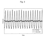
- Fig. 3 is a diagram illustrating changes in pressure over time during an anomaly of the hydraulic pump 1 shown in Fig. 1 .
- the horizontal axis represents time and the vertical axis represents pressure of the hydraulic pump 1.
- Fig. 3 shows changes in the pressure of the hydraulic pump 1 over time when there is a damage to part of the plurality of pistons 5.
- the change width of changes in pressure over time caused by the tilting of the swash plate 6, or the change width of changes in pressure over time caused by the operation of the hydraulic excavator 200 is larger than the range of such pressure pulsation amplitude (i.e., the change width of changes in pressure over time caused by the anomaly in the hydraulic pump 1). Therefore, for a precise and accurate diagnosis of the hydraulic pump 1, it is important to distinguish whether or not the changes in the pressure of the hydraulic pump 1 over time are caused by the anomaly in the hydraulic pump 1.
- Fig. 4 is a block diagram illustrating a functional configuration of the hydraulic excavator 200 including the diagnostic device 40 for diagnosing the hydraulic pump 1 shown in Fig. 1 .
- Fig. 5 is a diagram illustrating an exemplary display of an action instruction outputted from an action instruction section 42 shown in Fig. 4 .
- Fig. 6 is a diagram illustrating a sampling rate set by a measurement condition setting section 44 shown in Fig. 4 .
- Fig. 7 is a diagram showing a probability density distribution of measured values shown in Fig. 6 .
- Fig. 8 is a diagram showing an exemplary display of a determination result obtained by an anomaly determination section 47 shown in Fig. 4 .
- the diagnostic device 40 for diagnosing the hydraulic pump 1 is configured to include a processor and a storage device. Various functions of the diagnostic device 40 are implemented by the execution of programs stored in the storage device by the processor. Note that in the present embodiment, the diagnostic device 40 for diagnosing the hydraulic pump 1 is installed in the controller 25 of the hydraulic excavator 200.
- a temperature sensor 31 is a sensor for measuring a temperature of the hydraulic oil.
- the posture sensor 32 is a sensor for measuring a posture of the hydraulic excavator 200.
- the posture sensor 32 includes a boom angle sensor for measuring a rotation angle of the boom 204, an arm angle sensor for measuring a rotation angle of the arm 205, a bucket angle sensor for measuring a rotation angle of the bucket 206, and a turning angle sensor for measuring a turning angle of the upper turning body 202.
- the number-of-revolution sensor 33 is a sensor for measuring the number of revolutions of the prime mover 30.
- the operation amount sensor 34 is a sensor for measuring operation amounts of the operating lever 27 and the control dial 28.
- a display device 35 is connected to the output side of the diagnostic device 40.
- the display device 35 is part of the notification device 26, and serves as a display provided in a cab of the hydraulic excavator 200 in the present embodiment.
- the display device 35 may include a display provided in an information terminal of a user other than the operator of the hydraulic excavator 200, for example, a manager responsible for overall management of the construction machines, other than the hydraulic excavator 200, located away from the hydraulic excavator 200.
- the diagnostic device 40 includes a diagnostic condition setting section 41, a measurement execution section 45, a calculation section 46, an anomaly determination section 47, and an output section 48.
- the diagnostic condition setting section 41 sets a diagnostic condition for diagnosing the hydraulic pump 1.
- the diagnostic condition include a condition concerning a state or action of the hydraulic excavator 200, and a condition concerning measurement of the pressure of the hydraulic pump 1.
- the diagnostic condition setting section 41 includes an action instruction section 42, a monitoring section 43, and a measurement condition setting section 44.
- the action instruction section 42 outputs, to the output section 48, an action instruction for causing the hydraulic excavator 200 to perform a specific action so as to allow the hydraulic pump 1 to be diagnosed.
- the output section 48 causes the display device 35 to display the action instruction outputted from the action instruction section 42.
- the action instruction is information for instructing the operator to cause the hydraulic excavator 200 to perform the specific action, such that the state including the rotational speed of the hydraulic pump 1, the temperature of the hydraulic oil, and the posture and load of the hydraulic excavator 200 will shift to a state suitable for a diagnosis of the hydraulic pump 1.
- the action instruction section 42 outputs an action instruction for causing the display device 35 to display a screen instructing the operator to operate the hydraulic excavator 200 to perform a diagnostic action while showing the operator a difference between an actual posture and a diagnostic posture of the hydraulic excavator 200 so as to perform a predetermined diagnostic action after the front work device 203 (e.g., the boom 204, the boom 204 and the arm 205) of the hydraulic excavator 200 achieves a predetermined diagnostic posture.
- the front work device 203 e.g., the boom 204, the boom 204 and the arm 205
- the action instruction outputted from the action instruction section 42 may include a first action instruction 53 and a second action instruction 54, as shown in Fig. 5 .
- the first action instruction 53 is an action instruction for shifting the hydraulic excavator 200 to a predetermined state.
- the second action instruction 54 is an action instruction for causing the hydraulic excavator 200 placed in the predetermined state in accordance with the first action instruction 53 to perform a predetermined action.
- Fig. 5 shows an example of a screen 51 displayed on the display device 35, including the first action instruction 53 and the second action instruction 54.
- the first action instruction 53 is an instruction to the operator to empty the bucket 206 of the hydraulic excavator 200 and adjust items 55 such that an actual measurement value (Value) falls within a target range (Target). That is, the actual measurement value (Value) shown in Fig. 5 is an example of information corresponding to the actual posture of the hydraulic excavator 200, and the target range (Target) shown in Fig. 5 is an example of information corresponding to the diagnostic posture.
- the action instruction section 42 causes the display device 35 to display the screen 51 displaying both the actual measurement value (Value) and the target range (Target), so as to show the operator the difference between the actual posture and the diagnostic posture of the hydraulic excavator 200.
- the second action instruction 54 is an instruction to the operator to, after the operation in accordance with the first action instruction 53, operate the control dial 28 to set the number of revolutions of the prime mover 30 to minimum, and operate a boom-raising operating lever of the operating lever 27 with a full stroke for a relief for 30 seconds.
- examples of the other methods for showing the operator the difference between the actual posture and the diagnostic posture of the hydraulic excavator 200 include displaying, in an image display area 52 of the screen 51, side views or partial side views of two hydraulic excavators 200 corresponding to the actual posture and the diagnostic posture, or displaying a difference between the above-described actual measurement value (Value) and target range (Target) in the screen 51.
- the state including the rotational speed of the hydraulic pump 1, the temperature of the hydraulic oil, and the posture and load of the hydraulic excavator 200 shifts to a steady state suitable for a diagnosis of the hydraulic pump 1.
- the diagnostic device 40 measures the pressure of the hydraulic pump 1 and diagnoses the hydraulic pump 1.
- the diagnostic device 40 measures the pressure of the hydraulic pump 1 while the operator operates the boom-raising operating lever of the operating lever 27 with a full stroke for a relief for 30 seconds in accordance with the second action instruction 54.
- the diagnostic device 40 can stably measure the pressure of the hydraulic pump 1 with the condition concerning the state or action of the hydraulic excavator 200 always set to the same condition.
- the diagnostic device 40 can definitely distinguish whether or not changes in the pressure over time are caused by the anomaly in the hydraulic pump 1. Therefore, the diagnostic device 40 can accurately and stably diagnose the hydraulic pump 1.
- the monitoring section 43 acquires measured values of the temperature sensor 31, the posture sensor 32, the number-of-revolution sensor 33, the operation amount sensor 34, and the pressure sensor 24, and monitors whether the operator is operating the hydraulic excavator 200 in accordance with the action instruction outputted from the action instruction section 42.
- the monitoring section 43 outputs the measured values of the sensors and the monitoring result to the output section 48.
- the output section 48 causes the display device 35 to display the monitoring result outputted from the monitoring section 43, and the like.
- the diagnostic device 40 to notify the operator whether or not the operator is operating the hydraulic excavator 200 in accordance with the action instruction outputted from the action instruction section 42.
- the operator can adjust at an early stage the operation amount of the operating lever 27 or the control dial 28. Since the diagnostic device 40 can measure the pressure of the hydraulic oil with the condition concerning the state or action of the hydraulic excavator 200 always surely set to the same condition, the diagnostic device 40 can more accurately and stably diagnose the hydraulic pump 1.
- the diagnostic device 40 stores, as monitoring criteria, a monitoring parameter of the monitoring section 43 corresponding to the diagnostic posture and a variation of the monitoring parameter of the monitoring section 43 corresponding to the diagnostic action, as described above.
- the diagnostic device 40 determines whether or not the hydraulic excavator 200 has achieved the diagnostic posture instructed by the action instruction section 42 or determines whether or not the hydraulic excavator 200 has performed the diagnostic action.
- the diagnostic device 40 causes the display device 35 to display information indicating that the diagnostic device 40 was unable to perform a diagnosis under an appropriate condition (recommended posture and recommended action) (e.g., text information such as "Diagnosis Failed"). In such cases, the diagnostic device 40 again causes the action instruction section 42 to output an action instruction to operate the hydraulic excavator 200 to perform the diagnostic action after achieving the diagnostic posture. Note that if a diagnosis under an appropriate condition was performed, the diagnostic device 40 may also cause the display device 35 to display information indicating that the diagnosis under an appropriate condition was performed (e.g., text information such as "Successfully Diagnosed").
- the measurement condition setting section 44 sets a condition concerning measurement of the pressure of the hydraulic pump 1 in the measurement execution section 45. Specifically, the measurement condition setting section 44 sets a sampling condition in pressure measurement during a specific action (i.e., during a diagnostic action) of the hydraulic excavator 200 in the measurement execution section 45. In particular, the measurement condition setting section 44 sets a sampling rate in measurement of the pressure of the hydraulic pump 1. The sampling rate set by the measurement condition setting section 44 will be described in detail later with reference to Fig. 6 and Fig. 7 .
- the measurement execution section 45 measures the pressure of the hydraulic pump 1 during the specific action of the hydraulic excavator 200 in accordance with the condition set by the measurement condition setting section 44. Specifically, the measurement execution section 45 samples the pressure of the hydraulic pump 1 at the sampling rate set by the measurement condition setting section 44: The measurement execution section 45 samples the pressure of the hydraulic pump 1 over a predetermined sampling time using at least one of the pressure sensors 24a to 24c of the pressure sensor 24. Through this sampling, the measurement execution section 45 discretely acquires measured values of the pressure. The measured values of the pressure acquired by the measurement execution section 45 represent time-series data on the pressure discretely acquired. The measurement execution section 45 outputs the acquired measured values to the calculation section 46.
- the calculation section 46 calculates a pressure pulsation amplitude assumed as changes in the pressure over time based on the acquired measured values of the pressure. That is, the calculation section 46 acquires measured values of the pressure of the hydraulic pump 1 sampled during the specific action of the hydraulic excavator 200 under the sampling condition (specifically, sampling rate) set by the measurement condition setting section 44, and based on the acquired measured values of the pressure, calculates a pressure pulsation amplitude of the hydraulic pump 1. Specifically, the calculation section 46 performs statistical processing on the measured values of the pressure discretely acquired at the sampling rate set by the measurement condition setting section 44 to calculate a range of the measured values of the pressure, thus calculating a range of the pressure pulsation amplitude (oscillation). The calculation section 46 may calculate a distribution of the measured values of the pressure discretely acquired and calculate a pressure pulsation amplitude from the calculated distribution. The calculation section 46 outputs the calculated pressure pulsation amplitude to the anomaly determination section 47.
- the anomaly determination section 47 determines whether there is an anomaly in the hydraulic pump 1 based on the pressure pulsation amplitude calculated by the calculation section 46. Specifically, the anomaly determination section 47 stores in advance a threshold for determining whether there is an anomaly in the hydraulic pump 1. If the pressure pulsation amplitude calculated by the calculation section 46 is larger than or equal to the threshold stored in advance, the anomaly determination section 47 determines that there is an anomaly in the hydraulic pump 1. If the pressure pulsation amplitude calculated by the calculation section 46 is smaller than the threshold stored in advance, the anomaly determination section 47 determines that the hydraulic pump 1 is normal. The anomaly determination section 47 outputs an anomaly determination result for the hydraulic pump 1 to the output section 48.
- the anomaly determination section 47 may further store in advance a plurality of thresholds having different values.
- the plurality of thresholds having different values is used to identify an anomaly level of the hydraulic pump 1.
- the anomaly determination section 47 identifies an anomaly level of the hydraulic pump 1 by comparing the pressure pulsation amplitude calculated by the calculation section 46 with the plurality of thresholds having different values.
- the anomaly determination section 47 outputs the identified anomaly level of the hydraulic pump 1 to the output section 48.
- the output section 48 outputs, to the display device 35, the anomaly level of the hydraulic pump 1 identified by the anomaly determination section 47 and causes the display device 35 to display the anomaly level.
- the diagnostic device 40 can quantitatively indicate the severity of the anomaly in the hydraulic pump 1, and to notify a user of a sign of serious anomaly occurrence in the hydraulic pump 1.
- the user can schedule the repair timing or replacement timing of the hydraulic pump 1 before a malfunction of the hydraulic pump 1 occurs. Accordingly, the diagnostic device 40 can significantly reduce downtime of the hydraulic excavator 200, and can improve productivity of the hydraulic excavator 200.
- the pressure measurement device and the arithmetic processing device are very costly.
- the rotational speed of the hydraulic pump 1 is directly influenced by the change in the number of revolutions of the prime mover 30, the number of revolutions of the prime mover 30 momentarily changes during operation of the hydraulic excavator 200, and thus there is a possibility that the frequency component of the pressure could not be acquired stably. For this reason, it is difficult to perform a precise and accurate diagnosis of the hydraulic pump 1 with the frequency analysis method.
- the diagnostic device 40 of the present embodiment samples the pressure of the hydraulic pump 1 at a sampling rate smaller than the frequency of the pressure of the hydraulic pump 1 (pulsation frequency).
- the diagnostic device 40 performs statistical processing on the measured values of the pressure discretely acquired at the set sampling rate to calculate a pressure pulsation amplitude assumed as the changes in the pressure over time.
- the diagnostic device 40 determines whether there is an anomaly in the hydraulic pump 1 based on the calculated pressure pulsation amplitude. In this way, the diagnostic device 40 diagnoses the hydraulic pump 1.
- the diagnostic device 40 samples the pressure of the hydraulic pump 1 not at a sampling rate of around 0.5n times (n is an integer) the frequency of the pressure of the hydraulic pump 1 (pulsation frequency). For example, as shown in the upper graph 61 of Fig. 6 , consider a case where the hydraulic pump 1 is subjected to pressure pulsations, and the diagnostic device 40 samples the pressure at a sampling rate of 0.5 times the frequency of the pressure (pulsation frequency). In this case, the diagnostic device 40 acquires a measured value 64 of the pressure at a sampling rate of 0.5 times the frequency of the waveform 63 of the pressure (i.e., the waveform of the pressure pulsations).
- the range of the acquired measured value 64 differs from the range of the amplitude of the waveform 63 (the range from a peak value of a positive amplitude to a peak value of a negative amplitude).
- the probability density distribution of the measured value 64 clearly differs from the probability density distribution of the waveform 63. Such a phenomenon also applies to the case of measuring the pressure at a sampling rate of around 0.5n times the frequency of the waveform 63 of the pressure.
- the diagnostic device 40 samples the pressure of the hydraulic pump 1 at a sampling rate of around 0.5n times the frequency of the pressure of the hydraulic pump 1 (pulsation frequency), it is difficult to calculate so as to cover the entire range of the pressure pulsation amplitude assumed as the changes in the pressure over time.
- the diagnostic device 40 samples the pressure not at a sampling rate of around 0.5n times the frequency of the pressure of the hydraulic pump 1 (pulsation frequency).
- the diagnostic device 40 acquires a measured value 65 of the pressure.
- the range of the acquired measured value 65 (the range of the measured value 65 from a maximum to a minimum) coincides with the range of the amplitude of the waveform 63 (the range from a peak value of a positive amplitude to a peak value of a negative amplitude).
- the probability density distribution of the measured value 65 substantially coincides with the probability density distribution of the waveform 63. Accordingly, when the diagnostic device 40 samples the pressure of the hydraulic pump 1 not at a sampling rate of around 0.5n times the frequency of the pressure of the hydraulic pump 1 (pulsation frequency), it is possible to calculate so as to cover the entire range of the pressure pulsation amplitude assumed as the changes in the pressure over time.
- the sampling rate other than a sampling rate of around 0.5n times the frequency of the pressure of the hydraulic pump 1 (pulsation frequency) is a sampling rate that allows calculation over the entire range of the pressure pulsation amplitude.
- the frequency of the pressure of the hydraulic pump 1 can be obtained from the rotational speed of the hydraulic pump 1, that is, the number of revolutions of the prime mover 30 and the number of pistons 5 of the hydraulic pump 1.
- the sampling rate of around 0.5n times the frequency of the pressure of the hydraulic pump 1 can be obtained from the inverse of a sampling time.
- the measurement condition setting section 44 sets the sampling rate in measurement of the pressure of the hydraulic pump 1 to a sampling rate which is smaller than the frequency of the pressure (pulsation frequency) and which allows calculation over the entire range of the pressure pulsation amplitude.
- the measurement execution section 45 samples the pressure of the hydraulic pump 1 at the sampling rate set by the measurement condition setting section 44.
- the calculation section 46 calculates a range of the measured values of the pressure discretely acquired at the sampling rate set by the measurement condition setting section 44 to calculate a range of the pressure pulsation amplitude.
- the anomaly determination section 47 determines whether there is an anomaly in the hydraulic pump 1 based on the pressure pulsation amplitude calculated by the calculation section 46.
- the diagnostic device 40 can easily perform an accurate and stable diagnosis of the hydraulic pump 1.
- the output section 48 outputs, to the display device 35, the action instruction received from the action instruction section 42, the monitoring result received from the monitoring section 43, and the like, and causes the display device 35 to display them. Furthermore, the output section 48 outputs, to the display device 35, a determination result obtained by the anomaly determination section 47 and causes the display device 35 to display the determination result. The output section 48 causes the display device 35 to display the determination result obtained by the anomaly determination section 47 using numerical values, characters, figures, colors, and the like.
- the hydraulic excavator 200 has a plurality of hydraulic pumps 1 mounted thereon.
- the calculation section 46 acquires measured values of the pressure for each of the plurality of hydraulic pumps 1, and calculates a pressure pulsation amplitude for each of the plurality of hydraulic pumps 1.
- the anomaly determination section 47 determines whether there is an anomaly in each of the plurality of hydraulic pumps 1.
- the output section 48 causes the display device 35 to collectively display, in one screen of the display device 35, the determination result for each of the plurality of hydraulic pumps 1 obtained by the anomaly determination section 47.
- Fig. 8 shows an exemplary display on the display device 35, showing a screen 81 including an area 82 displaying a determination result obtained by the anomaly determination section 47.
- the screen 81 collectively displays an anomaly determination result 87 for each of four hydraulic pumps 83 to 86 as the plurality of hydraulic pumps 1.
- the display device 35 schematically displays the layout of the hydraulic pumps 83 to 86 mounted on the hydraulic excavator 200, and then overlays the diagnosis results for the hydraulic pumps 83 to 86 obtained by the anomaly determination section 47 on the layout of the hydraulic pumps 83 to 86.
- diagnostic device 40 to cause the display device 35 to display the diagnosis results for the plurality of hydraulic pumps 1 mounted on the same hydraulic excavator 200 such that the user can intuitively compare the diagnosis results.
- Fig. 9 is a flowchart of a diagnostic process performed by the diagnostic device 40 shown in Fig. 4 .
- a threshold Pa(0) for determining whether there is an anomaly in the hydraulic pump 1
- the larger the argument i the smaller the threshold Pa(i) and the smaller the anomaly level of the hydraulic pump 1.
- the threshold Pa(0) and the threshold Pa(i) may be values set in advance or values calculated in measurement of the pressure of the hydraulic pump 1.
- the threshold Pa(0) and the threshold Pa(i) may be values calculated based on a time-average of the pressure measured in the other hydraulic pump 1 of the same type mounted on the same hydraulic excavator 200 or values calculated based on a pressure pulsation amplitude calculated in the other hydraulic pump 1.
- the threshold Pa(0) and the threshold Pa(i) may be values obtained empirically from the operating situation of the hydraulic pump 1, such as the rotational speed of the hydraulic pump 1.
- step s1 the diagnostic device 40 measures a pressure of the hydraulic pump 1 and acquires a measured value of the pressure.
- step s2 the diagnostic device 40 calculates a pressure pulsation amplitude Pa based on the acquired measured value.
- step s3 the diagnostic device 40 determines whether or not the calculated pressure pulsation amplitude Pa is larger than or equal to the threshold Pa(0). If the pressure pulsation amplitude Pa is smaller than the threshold Pa(0), the diagnostic device 40 moves to step s4. If the pressure pulsation amplitude Pa is larger than or equal to the threshold Pa(0), the diagnostic device 40 moves to step s5.
- step s4 the diagnostic device 40 determines that the hydraulic pump 1 is normal. Thereafter, the diagnostic device 40 moves to step s10.
- step s5 the diagnostic device 40 determines that there is an anomaly in the hydraulic pump 1.
- step s6 the diagnostic device 40 sets the argument i of the threshold Pa(i) to its lower limit 1.
- step s7 the diagnostic device 40 determines whether the argument i of the threshold Pa(i) is larger than its upper limit n. If the argument i is larger than its upper limit n, the diagnostic device 40 moves to step s10. If the argument i is smaller than or equal to its upper limit n, the diagnostic device 40 moves to step s8.
- step s8 the diagnostic device 40 determines whether or not the calculated pressure pulsation amplitude Pa is larger than or equal to the threshold Pa(i). If the pressure pulsation amplitude Pa is larger than or equal to the threshold Pa(i), the diagnostic device 40 identifies an anomaly level of the hydraulic pump 1 corresponding to the threshold Pa(i). Thereafter, the diagnostic device 40 moves to step s10. The anomaly level of the hydraulic pump 1 corresponding to the threshold Pa(i) is defined in advance. Meanwhile, if the pressure pulsation amplitude Pa is smaller than the threshold Pa(i), the diagnostic device 40 moves to step s9.
- step s9 the diagnostic device 40 increments the argument i of the threshold Pa(i). Thereafter, the diagnostic device 40 moves to step s7.
- step s10 the diagnostic device 40 outputs, to the display device 35, the result of the determining whether there is an anomaly in the hydraulic pump 1 and the identified anomaly level of the hydraulic pump 1, and causes the display device 35 to display them. Thereafter, the diagnostic device 40 ends the diagnostic process shown in Fig. 9 .
- Fig. 10 is a diagram showing an exemplary display of the anomaly level of the hydraulic pump 1 identified through the diagnostic process shown in Fig. 9 .
- Fig. 10 shows an exemplary display on the display device 35, showing a screen 101 including an area 102 displaying transitions of anomaly levels of two hydraulic pumps 103, 104 as the plurality of hydraulic pumps 1.
- the screen 101 collectively displays the transitions of the anomaly levels of the hydraulic pumps 103, 104 in a predetermined time period from the past to the present.
- the user may change the display content in the area 102, such as the time period of transitions of the anomaly levels to be displayed, for example, by tapping an icon 105 on the screen 101.
- the anomaly level of the hydraulic pump 104 is generally stable.
- Fig. 10 shows an exemplary display on the display device 35, showing a screen 101 including an area 102 displaying transitions of anomaly levels of two hydraulic pumps 103, 104 as the plurality of hydraulic pumps 1.
- the screen 101 collectively displays the transitions of the anomaly levels of the hydraulic pumps 103, 104 in a predetermined time period from the past to the present.
- the user may change the display content in the area
- the anomaly level of the hydraulic pump 103 suddenly rises at a certain point, meaning that a serious anomaly has occurred in the hydraulic pump 103. Since the diagnostic device 40 can notify the user of a sign of serious anomaly occurrence as in the hydraulic pump 103 shown in Fig. 10 , the diagnostic device 40 can prompt the user to repair or replace the hydraulic pump 1.
- the diagnostic device 40 is a diagnostic device for diagnosing the hydraulic pump 1 mounted on the hydraulic excavator 200 and driven by the prime mover 30 of the hydraulic excavator 200 to supply pressure oil to the hydraulic actuator 29 of the hydraulic excavator 200.
- the diagnostic device 40 includes the action instruction section 42 that outputs an action instruction for causing the hydraulic actuator 29 to perform a specific action, the measurement condition setting section 44 that sets a sampling condition in measurement of the pressure of the hydraulic pump 1 during the specific action, the calculation section 46 that acquires a measured value of the pressure sampled during the specific action under the set sampling condition, and calculates a pressure pulsation amplitude of the hydraulic pump 1, the anomaly determination section 47 that determines whether there is an anomaly in the hydraulic pump 1 based on the calculated pressure pulsation amplitude, and the output section 48 that outputs a determination result obtained by the anomaly determination section 47 to the display device 35.
- the diagnostic device 40 can stably measure the pressure of the hydraulic pump 1 with the condition concerning the state or action of the hydraulic excavator 200 always set to the same condition.
- the diagnostic device 40 can definitely distinguish whether or not changes in the pressure of the hydraulic pump 1 over time are caused by the anomaly in the hydraulic pump 1. Therefore, the diagnostic device 40 can accurately and stably diagnose the hydraulic pump 1. Consequently, according to the present embodiment, it is possible to provide the diagnostic device 40 for diagnosing the hydraulic pump 1 capable of performing a precise and accurate diagnosis.
- the sampling rate in measurement of the pressure of the hydraulic pump 1 set by the measurement condition setting section 44 is smaller than the frequency of the pressure of the hydraulic pump 1 (pulsation frequency) so as to allow calculation over the entire range of the pressure pulsation amplitude.
- the measurement condition setting section 44 may set the number of revolutions of the prime mover 30 that drives the hydraulic pump 1, instead of the sampling rate in measurement of the pressure of the hydraulic pump 1, so as to allow calculation over the entire range of the pressure pulsation amplitude. Specifically, the measurement condition setting section 44 may set the number of revolutions of the prime mover 30 such that the set sampling rate is smaller than the frequency of the pressure of the hydraulic pump 1 (pulsation frequency). Accordingly, the action instruction section 42 may output an action instruction for rotating the prime mover 30 according to the set number of revolutions.
- the diagnostic device 40 can easily perform an accurate and stable diagnosis of the hydraulic pump 1 as compared to the case of using the frequency analysis method. Accordingly, the diagnostic device 40 is applicable to the hydraulic excavator 200.
- the hydraulic excavator 200 is a construction machine including the lower. traveling body 201 that is able to self-propel, the upper turning body 202 turnably supported relative to the lower traveling body 201, the front work device 203 provided on the upper turning body 202, the hydraulic actuator 29 that drives the front work device 203, the hydraulic pump 1 that supplies pressure oil to the hydraulic actuator 29, the pressure sensor 24 that measures the pressure of the hydraulic pump 1, and the display device 35 that displays various kinds of information to an operator.
- the hydraulic excavator 200 includes the controller 25 that causes the display device 35 to display an operation instruction for an action of the front work device 203 and diagnoses the hydraulic pump 1.
- the controller 25 causes the display device 35 to display the screen 51 instructing the operator to operate the hydraulic excavator 200 to perform a diagnostic action while showing the operator a difference between an actual posture and a diagnostic posture of the hydraulic excavator 200.
- the controller 25 sets a sampling condition in measurement of the pressure during the diagnostic action.
- the controller 25 calculates a pressure pulsation amplitude of the hydraulic pump 1 based on the measured value of the pressure sampled during the diagnostic action under the set sampling condition.
- the controller 25 determines whether there is an anomaly in the hydraulic pump 1 based on the calculated pressure pulsation amplitude.
- the controller 25 causes the display device 35 to display a result of the determining whether there is an anomaly.
- the hydraulic excavator 200 can stably measure the pressure of the hydraulic pump 1 with the condition concerning the state or action of the hydraulic excavator 200 always set to the same condition.
- the hydraulic excavator 200 can definitely distinguish whether or not changes in the pressure of the hydraulic pump 1 over time are caused by the anomaly in the hydraulic pump 1. Therefore, the hydraulic excavator 200 can accurately and stably diagnose the hydraulic pump 1. Consequently, according to the present embodiment, it is possible to provide the hydraulic excavator 200 capable of performing a precise and accurate diagnosis of the hydraulic pump 1.
Landscapes
- Engineering & Computer Science (AREA)
- General Engineering & Computer Science (AREA)
- Mining & Mineral Resources (AREA)
- Civil Engineering (AREA)
- Structural Engineering (AREA)
- Mechanical Engineering (AREA)
- Physics & Mathematics (AREA)
- Fluid Mechanics (AREA)
- Control Of Positive-Displacement Pumps (AREA)
Abstract
Description
- The present invention relates to a pump diagnostic device, and a construction machine including the diagnostic device.
- There is a device for diagnosing a hydraulic pump mounted on a construction machine, such as a hydraulic excavator, by analyzing a pressure of the hydraulic pump, such as a discharge pressure or a drain pressure, without separating the hydraulic pump into components (for example, Patent Literature 1).
-
Patent Literature 1 discloses a technique of diagnosing a hydraulic pump based on the frequency component of the pressure coinciding with the rotational frequency of the hydraulic pump. According toPatent Literature 1, when friction occurs in a piston shoe of the hydraulic pump, the frequency component of the pressure coinciding with the rotational frequency of the hydraulic pump increases. Thus, through analysis of such a frequency component of the pressure, the technique ofPatent Literature 1 can diagnose the hydraulic pump. - Patent Literature 1:
JP 2013-170509 A - However, in the operating construction machine performing digging action, turning action, and the like, the load of the hydraulic pump momentarily changes, and accordingly the rotational speed of the hydraulic pump also momentarily changes. Thus, there is a possibility that the frequency component of the pressure of the hydraulic pump could not be acquired stably. For this reason, the technique disclosed in
Patent Literature 1 needs some improvement to achieve a precise and accurate diagnosis. - In view of the above, it is an object of the present invention to provide a pump diagnostic device and a construction machine capable of performing a precise and accurate diagnosis.
- To solve the above issue, the pump diagnostic device according to the present invention is a diagnostic device for diagnosing a pump mounted on a construction machine and driven by a prime mover of the construction machine to supply pressure oil to a hydraulic actuator of the construction machine. The diagnostic device includes: an action instruction section that outputs an action instruction for causing the hydraulic actuator to perform a specific action; a measurement condition setting section that sets a sampling condition in measurement of a pressure of the pump during the specific action; a calculation section that acquires a measured value of the pressure sampled during the specific action under the set sampling condition, and calculates a pressure pulsation amplitude of the pump; an anomaly determination section that determines whether there is an anomaly in the pump based on the calculated pressure pulsation amplitude; and an output section that outputs a determination result obtained by the anomaly determination section to a display device.
- In addition, the construction machine according to the present invention is a construction machine including a lower traveling body that is able to self-propel, an upper turning body turnably supported relative to the lower traveling body, a front work device provided on the upper turning body, a hydraulic actuator that drives the front work device, a pump that supplies pressure oil to the hydraulic actuator, a pressure sensor that measures a pressure of the pump, and a display device that displays various kinds of information to an operator. The construction machine includes a controller that causes the display device to display an operation instruction for an action of the front work device and diagnoses the pump. The controller is configured to: cause the display device to display a screen instructing the operator to operate the construction machine to perform a diagnostic action while showing the operator a difference between an actual posture and a diagnostic posture of the construction machine; set a sampling condition in measurement of the pressure during the diagnostic action; calculate a pressure pulsation amplitude of the pump based on a measured value of the pressure sampled during the diagnostic action under the set sampling condition; determine whether there is an anomaly in the pump based on the calculated pressure pulsation amplitude; and cause the display device to display a result of the determining whether there is an anomaly.
- According to the present invention, it is possible to provide a pump diagnostic device and a construction machine capable of performing a precise and accurate diagnosis.
-
-
Fig. 1 is a view of a configuration of a hydraulic pump. -
Fig. 2 is a diagram illustrating a configuration of a hydraulic excavator including the hydraulic pump shown inFig. 1 . -
Fig. 3 is a diagram illustrating changes in pressure over time during an anomaly of the hydraulic pump shown inFig. 1 . -
Fig. 4 is a block diagram illustrating a functional configuration of the hydraulic excavator including a diagnostic device for diagnosing the hydraulic pump shown inFig. 1 . -
Fig. 5 is a diagram illustrating an exemplary display of an action instruction outputted from an action instruction section shown inFig. 4 . -
Fig. 6 is a diagram illustrating a sampling rate set by a measurement condition setting section shown inFig. 4 . -
Fig. 7 is a diagram showing a probability density distribution of measured values shown inFig. 6 . -
Fig. 8 is a diagram showing an exemplary display of a determination result obtained by an anomaly determination section shown inFig. 4 . -
Fig. 9 is a flowchart of a diagnostic process performed by the diagnostic device shown inFig. 4 . -
Fig. 10 is a diagram showing an exemplary display of an anomaly level of the hydraulic pump identified through the diagnostic process shown inFig. 9 . - Hereinafter, embodiments of the present invention will be described with reference to the drawings. Unless otherwise specified, elements denoted by identical reference signs in the embodiments have the same function in the embodiments, and repeated description thereof will be omitted.
- In the present embodiment, as the pump diagnostic device, a
diagnostic device 40 for diagnosing ahydraulic pump 1 discharging hydraulic oil that transmits power to the elements of a construction machine will be described by way of example. In the present embodiment, as the construction machine, ahydraulic excavator 200 as shown inFig. 5 will be described by way of example, where thediagnostic device 40 is mounted on thehydraulic excavator 200. However, the diagnostic device according to the present invention may be applicable also to a hydraulic pump mounted on construction machines other than thehydraulic excavator 200, for example, wheel loaders, dump trucks, or road machines. - Furthermore, the diagnostic device according to the present invention may also be provided outside of the construction machine. In this case, for example, the diagnostic device is configured to be able to communicate with the construction machine or the hydraulic pump. Further, the diagnostic device may be configured to receive information required for diagnosis from the construction machine or the hydraulic pump and execute a diagnostic process, and also to transmit an instruction required for diagnosis and a diagnosis result to the construction machine.
-
Fig. 1 is a view of a configuration of thehydraulic pump 1.Fig. 1 is a schematic cross-sectional view taken along an axial direction of thehydraulic pump 1. - The
hydraulic pump 1 shown inFig. 1 is a variable-displacement swash-plate type axial piston pump. Thehydraulic pump 1 may be a bent-axis type piston pump, a vane pump, or a gear pump. Thehydraulic pump 1 is used in the construction machine, such as thehydraulic excavator 200, and is driven to rotate by aprime mover 30, such as an engine or motor. Thehydraulic pump 1 includes acasing 2, ashaft 3, acylinder block 4,pistons 5, aswash plate 6, and avalve plate 7. - The
casing 2 includes a closed-bottomedcylindrical casing body 8, and alid 9 that closes an opening of thecasing body 8. Thelid 9 and thecasing body 8 form adrain oil chamber 10 therebetween. Thecasing body 8 is provided with adrain port 11. Thedrain port 11 is connected to anoil tank 13 that stores hydraulic oil, via adrain pipe 12. Theshaft 3 is rotatably supported in thecasing 2 and rotates with the rotation of theprime mover 30. - The
cylinder block 4 is fixed to the periphery of theshaft 3 via a spline provided on the periphery of theshaft 3. Thecylinder block 4 rotates with the rotation of theshaft 3, inside of thecasing body 8. Thecylinder block 4 is disposed such that one end face faces theswash plate 6 and the other end face is slidable on thevalve plate 7. - The
cylinder block 4 is provided with a plurality ofcylinder holes 14. Thecylinder holes 14 are disposed circumferentially and equidistantly around theshaft 3 in thecylinder block 4. Eachcylinder hole 14 is provided to extend parallel to the axial direction of thecylinder block 4. Eachcylinder hole 14 is open toward thevalve plate 7, and is in communication with adischarge port 15 and asuction port 16. - The
piston 5 is disposed so as to be slidable inside of eachcylinder hole 14. On theswash plate 6 side of thepiston 5, ashoe 18 is provided so as to be swingable relative to thepiston 5. Eachpiston 5 reciprocates in thecylinder hole 14 along the axial direction with the rotation of thecylinder block 4. Accordingly, eachpiston 5 sucks hydraulic oil from thesuction port 16 into thecylinder hole 14, compresses the sucked hydraulic oil, and discharges pressure oil from thedischarge port 15. Theshoe 18 slidably abuts on the smooth surface of theswash plate 6. Theshoe 18 slides in a circular orbit with respect to the smooth surface of theswash plate 6 with the rotation of thecylinder block 4. - The
swash plate 6 is supported so as to be able to tilt by a swashplate support member 19 provided on thelid 9 of thecasing 2. The surface of theswash plate 6 on the side opposite to thelid 9 is a smooth surface on which theshoe 18 slides. With the sliding of theshoe 18 on the smooth surface of theswash plate 6 with the rotation of thecylinder block 4, thepiston 5 can reciprocate in thecylinder hole 14. The surface of theswash plate 6 on the side adjacent to thelid 9 is provided with a pair of legs (only one of them is shown) of convex curved surfaces. The pair of legs provided on theswash plate 6 conforms to a pair of concave curved surfaces (only one of them is shown) provided on the surface of the swashplate support member 19 on the side opposite to thelid 9. - Here, a small gap (not shown) is formed between the
cylinder hole 14 and thepiston 5 to increase the sliding property of thepiston 5. This gap is in communication with thedrain oil chamber 10 of thecasing 2. Part of the pressure oil in thecylinder hole 14 leaks out through this gap into thedrain oil chamber 10 of thecasing 2. Further, a small gap (not shown) is formed between theshoe 18 and theswash plate 6 to increase the sliding property of theshoe 18. This gap is in communication with the inside of thecylinder hole 14 via a passage provided in the inside of theshoe 18 and thepiston 5. Part of the pressure oil in thecylinder hole 14 leaks out through this gap into thedrain oil chamber 10 of thecasing 2. -
Fig. 2 is a diagram illustrating a configuration of thehydraulic excavator 200 including thehydraulic pump 1 shown inFig. 1 . - The
drain port 11 of thehydraulic pump 1 is connected to theoil tank 13 via thedrain pipe 12. Thesuction port 16 of thehydraulic pump 1 is connected to theoil tank 13 via thesuction pipe 20. Thehydraulic pump 1 sucks the hydraulic oil supplied from theoil tank 13 via thesuction pipe 20. Thedischarge port 15 of thehydraulic pump 1 is connected to acontrol valve 22 via adischarge pipe 21. Thehydraulic pump 1 pressure-feeds the pressure oil to thecontrol valve 22 via thedischarge pipe 21. Thecontrol valve 22 distributes the pressure oil to eachhydraulic actuator 29 of thehydraulic excavator 200. - The
hydraulic excavator 200 includes alower traveling body 201 that is able to self-propel, anupper turning body 202 turnably supported relative to thelower traveling body 201, and afront work device 203 provided on the upper turning body 202 (seeFig. 5 ). Thefront work device 203 includes aboom 204 driven by a boom cylinder, anarm 205 driven by an arm cylinder, and abucket 206 driven by a bucket cylinder. Examples of thehydraulic actuator 29 of thehydraulic excavator 200 include the boom cylinder, the arm cylinder, the bucket cylinder, a turning motor, or a traveling motor. Return oil from thehydraulic actuator 29 is returned to theoil tank 13 through thecontrol valve 22 and areturn pipe 23. - The
discharge pipe 21, thedrain pipe 12, and thesuction pipe 20 are respectively provided withpressure sensors 24a to 24c for measuring various types of pressure of thehydraulic pump 1. Thepressure sensor 24a measures a discharge pressure of thehydraulic pump 1. Thepressure sensor 24b measures a drain pressure of thehydraulic pump 1. Thepressure sensor 24c measures a suction pressure of thehydraulic pump 1. Output signals of thepressure sensors 24a to 24c are inputted to acontroller 25 that controls various actions of the hydraulic excavator 200 (i.e., controls the actions of thehydraulic pump 1, thecontrol valve 22, and theprime mover 30, for example). Note that in the present embodiment, thepressure sensors 24a to 24c may also be collectively referred to as the "pressure sensor 24." - The
controller 25 calculates measured values of the pressure of thehydraulic pump 1 from the output signals of thepressure sensor 24. Thecontroller 25 includes a calculation section that calculates a pressure wave amplitude of thehydraulic pump 1 from time-series data on the measured values, and a storage section that stores a threshold for determining whether there is an anomaly in thehydraulic pump 1. Thecontroller 25 compares the pressure wave amplitude with the threshold to diagnose thehydraulic pump 1, and outputs a diagnosis result to anotification device 26. Thecontroller 25 also outputs, to thenotification device 26, an action instruction for causing thehydraulic excavator 200 to perform a specific action as a diagnostic condition for diagnosing thehydraulic pump 1. - The
notification device 26 notifies an operator of thehydraulic excavator 200, that is, a crew of thehydraulic excavator 200, of the diagnosis result or action instruction. Thenotification device 26 may also notify a user other than the operator, such as a manager of thehydraulic excavator 200, of the diagnosis result or action instruction. The operator operates an operatinglever 27 and an engine control dial 28 (hereinafter also referred to as the "control dial 28") in accordance with the action instruction provided by thenotification device 26, and operates thehydraulic excavator 200 so as to allow thehydraulic pump 1 to be diagnosed. Note that thecontrol dial 28 is an operating device for controlling the number of revolutions of the engine that is theprime mover 30. The operatinglever 27 is an operating device for controlling each component of thehydraulic excavator 200, such as thelower traveling body 201, theupper turning body 202, and thefront work device 203. - In addition, in response to the operator's operation of the operating
lever 27 and thecontrol dial 28, thecontroller 25 controls the actions of thehydraulic excavator 200. Specifically, operation signals outputted from the operatinglever 27 and thecontrol dial 28 are inputted to thecontroller 25. Thecontroller 25 controls the actions of thecontrol valve 22, theprime mover 30, and thehydraulic pump 1 according to the received operation signals. At this time, thecontroller 25 monitors whether the posture of thehydraulic excavator 200 and the pressure of thehydraulic pump 1 are in a condition (i.e., diagnostic posture and diagnostic pressure) that is expected when the operation in accordance with the action instruction (i.e., the operation corresponding to the diagnostic action) is performed. If they satisfy the diagnostic condition, thehydraulic pump 1 is diagnosed. -
Fig. 3 is a diagram illustrating changes in pressure over time during an anomaly of thehydraulic pump 1 shown inFig. 1 . InFig. 3 , the horizontal axis represents time and the vertical axis represents pressure of thehydraulic pump 1.Fig. 3 shows changes in the pressure of thehydraulic pump 1 over time when there is a damage to part of the plurality ofpistons 5. - As described above, when the
hydraulic pump 1 is driven by theprime mover 30, thecylinder block 4 rotates and thepiston 5 reciprocates in thecylinder hole 14. At this time, part of the pressure oil in thecylinder hole 14 leaks out into thedrain oil chamber 10 of thecasing 2 through the gap between thecylinder hole 14 and thepiston 5 and the gap between theshoe 18 and theswash plate 6. When there is any damage to thepiston 5, thecylinder hole 14, or theshoe 18, these gaps become larger. If these gaps become larger, the amount of movement of the hydraulic oil between thedischarge port 15,suction port 16, or drainport 11, and thedrain oil chamber 10 increases. In this case, the pressure (the discharge pressure, the suction pressure, or the drain pressure) at thedischarge port 15, thesuction port 16, or thedrain port 11 changes. - Specifically, when the damaged
piston 5,cylinder hole 14, orshoe 18 passes across thedischarge port 15, the pressure in thedrain oil chamber 10 rises. Then, as shown inFig. 3 , it is assumed that pressure pulsations (broken lines inFig. 3 ) having a period that coincides with an integer multiple of a rotation period of thehydraulic pump 1 occur in the pipes connected to the ports of thehydraulic pump 1. Comparing the assumed pressure pulsation amplitude with the threshold allows a diagnosis of thehydraulic pump 1. - However, normally, for example, the change width of changes in pressure over time caused by the tilting of the
swash plate 6, or the change width of changes in pressure over time caused by the operation of thehydraulic excavator 200 is larger than the range of such pressure pulsation amplitude (i.e., the change width of changes in pressure over time caused by the anomaly in the hydraulic pump 1). Therefore, for a precise and accurate diagnosis of thehydraulic pump 1, it is important to distinguish whether or not the changes in the pressure of thehydraulic pump 1 over time are caused by the anomaly in thehydraulic pump 1. -
Fig. 4 is a block diagram illustrating a functional configuration of thehydraulic excavator 200 including thediagnostic device 40 for diagnosing thehydraulic pump 1 shown inFig. 1 .Fig. 5 is a diagram illustrating an exemplary display of an action instruction outputted from anaction instruction section 42 shown inFig. 4 .Fig. 6 is a diagram illustrating a sampling rate set by a measurementcondition setting section 44 shown inFig. 4 .Fig. 7 is a diagram showing a probability density distribution of measured values shown inFig. 6 .Fig. 8 is a diagram showing an exemplary display of a determination result obtained by ananomaly determination section 47 shown inFig. 4 . - The
diagnostic device 40 for diagnosing thehydraulic pump 1 is configured to include a processor and a storage device. Various functions of thediagnostic device 40 are implemented by the execution of programs stored in the storage device by the processor. Note that in the present embodiment, thediagnostic device 40 for diagnosing thehydraulic pump 1 is installed in thecontroller 25 of thehydraulic excavator 200. - To the input side of the
diagnostic device 40, as shown inFig. 4 , atemperature sensor 31, aposture sensor 32, a number-of-revolution sensor 33, anoperation amount sensor 34, and thepressure sensor 24, which are mounted on thehydraulic excavator 200, are connected. Thetemperature sensor 31 is a sensor for measuring a temperature of the hydraulic oil. Theposture sensor 32 is a sensor for measuring a posture of thehydraulic excavator 200. Theposture sensor 32 includes a boom angle sensor for measuring a rotation angle of theboom 204, an arm angle sensor for measuring a rotation angle of thearm 205, a bucket angle sensor for measuring a rotation angle of thebucket 206, and a turning angle sensor for measuring a turning angle of theupper turning body 202. The number-of-revolution sensor 33 is a sensor for measuring the number of revolutions of theprime mover 30. Theoperation amount sensor 34 is a sensor for measuring operation amounts of the operatinglever 27 and thecontrol dial 28. - To the output side of the
diagnostic device 40, adisplay device 35 is connected. Thedisplay device 35 is part of thenotification device 26, and serves as a display provided in a cab of thehydraulic excavator 200 in the present embodiment. Note that when thediagnostic device 40 is provided outside of thehydraulic excavator 200, thedisplay device 35 may include a display provided in an information terminal of a user other than the operator of thehydraulic excavator 200, for example, a manager responsible for overall management of the construction machines, other than thehydraulic excavator 200, located away from thehydraulic excavator 200. - In the present embodiment, the
diagnostic device 40 includes a diagnosticcondition setting section 41, ameasurement execution section 45, acalculation section 46, ananomaly determination section 47, and anoutput section 48. - The diagnostic
condition setting section 41 sets a diagnostic condition for diagnosing thehydraulic pump 1. Examples of the diagnostic condition include a condition concerning a state or action of thehydraulic excavator 200, and a condition concerning measurement of the pressure of thehydraulic pump 1. Specifically, the diagnosticcondition setting section 41 includes anaction instruction section 42, amonitoring section 43, and a measurementcondition setting section 44. - The
action instruction section 42 outputs, to theoutput section 48, an action instruction for causing thehydraulic excavator 200 to perform a specific action so as to allow thehydraulic pump 1 to be diagnosed. Theoutput section 48 causes thedisplay device 35 to display the action instruction outputted from theaction instruction section 42. In the present embodiment, the action instruction is information for instructing the operator to cause thehydraulic excavator 200 to perform the specific action, such that the state including the rotational speed of thehydraulic pump 1, the temperature of the hydraulic oil, and the posture and load of thehydraulic excavator 200 will shift to a state suitable for a diagnosis of thehydraulic pump 1. - In the present embodiment, the
action instruction section 42 outputs an action instruction for causing thedisplay device 35 to display a screen instructing the operator to operate thehydraulic excavator 200 to perform a diagnostic action while showing the operator a difference between an actual posture and a diagnostic posture of thehydraulic excavator 200 so as to perform a predetermined diagnostic action after the front work device 203 (e.g., theboom 204, theboom 204 and the arm 205) of thehydraulic excavator 200 achieves a predetermined diagnostic posture. - More specifically, the action instruction outputted from the
action instruction section 42 may include afirst action instruction 53 and asecond action instruction 54, as shown inFig. 5 . Thefirst action instruction 53 is an action instruction for shifting thehydraulic excavator 200 to a predetermined state. Thesecond action instruction 54 is an action instruction for causing thehydraulic excavator 200 placed in the predetermined state in accordance with thefirst action instruction 53 to perform a predetermined action. -
Fig. 5 shows an example of ascreen 51 displayed on thedisplay device 35, including thefirst action instruction 53 and thesecond action instruction 54. In the example ofFig. 5 , thefirst action instruction 53 is an instruction to the operator to empty thebucket 206 of thehydraulic excavator 200 and adjustitems 55 such that an actual measurement value (Value) falls within a target range (Target). That is, the actual measurement value (Value) shown inFig. 5 is an example of information corresponding to the actual posture of thehydraulic excavator 200, and the target range (Target) shown inFig. 5 is an example of information corresponding to the diagnostic posture. Theaction instruction section 42 causes thedisplay device 35 to display thescreen 51 displaying both the actual measurement value (Value) and the target range (Target), so as to show the operator the difference between the actual posture and the diagnostic posture of thehydraulic excavator 200. - In the example of
Fig. 5 , thesecond action instruction 54 is an instruction to the operator to, after the operation in accordance with thefirst action instruction 53, operate thecontrol dial 28 to set the number of revolutions of theprime mover 30 to minimum, and operate a boom-raising operating lever of the operatinglever 27 with a full stroke for a relief for 30 seconds. - Note that examples of the other methods for showing the operator the difference between the actual posture and the diagnostic posture of the
hydraulic excavator 200 include displaying, in animage display area 52 of thescreen 51, side views or partial side views of twohydraulic excavators 200 corresponding to the actual posture and the diagnostic posture, or displaying a difference between the above-described actual measurement value (Value) and target range (Target) in thescreen 51. - By the operator's operation of the
hydraulic excavator 200 in accordance with thefirst action instruction 53 and thesecond action instruction 54, the state including the rotational speed of thehydraulic pump 1, the temperature of the hydraulic oil, and the posture and load of thehydraulic excavator 200 shifts to a steady state suitable for a diagnosis of thehydraulic pump 1. During this steady state, thediagnostic device 40 measures the pressure of thehydraulic pump 1 and diagnoses thehydraulic pump 1. In particular, thediagnostic device 40 measures the pressure of thehydraulic pump 1 while the operator operates the boom-raising operating lever of the operatinglever 27 with a full stroke for a relief for 30 seconds in accordance with thesecond action instruction 54. - Accordingly, the
diagnostic device 40 can stably measure the pressure of thehydraulic pump 1 with the condition concerning the state or action of thehydraulic excavator 200 always set to the same condition. Thus, thediagnostic device 40 can definitely distinguish whether or not changes in the pressure over time are caused by the anomaly in thehydraulic pump 1. Therefore, thediagnostic device 40 can accurately and stably diagnose thehydraulic pump 1. - The
monitoring section 43 acquires measured values of thetemperature sensor 31, theposture sensor 32, the number-of-revolution sensor 33, theoperation amount sensor 34, and thepressure sensor 24, and monitors whether the operator is operating thehydraulic excavator 200 in accordance with the action instruction outputted from theaction instruction section 42. Themonitoring section 43 outputs the measured values of the sensors and the monitoring result to theoutput section 48. Theoutput section 48 causes thedisplay device 35 to display the monitoring result outputted from themonitoring section 43, and the like. - This allows the
diagnostic device 40 to notify the operator whether or not the operator is operating thehydraulic excavator 200 in accordance with the action instruction outputted from theaction instruction section 42. The operator can adjust at an early stage the operation amount of the operatinglever 27 or thecontrol dial 28. Since thediagnostic device 40 can measure the pressure of the hydraulic oil with the condition concerning the state or action of thehydraulic excavator 200 always surely set to the same condition, thediagnostic device 40 can more accurately and stably diagnose thehydraulic pump 1. - Further, in the present embodiment, the
diagnostic device 40 stores, as monitoring criteria, a monitoring parameter of themonitoring section 43 corresponding to the diagnostic posture and a variation of the monitoring parameter of themonitoring section 43 corresponding to the diagnostic action, as described above. Thediagnostic device 40, based on the situation of divergence of the actual monitoring result from the parameters serving as the monitoring criteria, determines whether or not thehydraulic excavator 200 has achieved the diagnostic posture instructed by theaction instruction section 42 or determines whether or not thehydraulic excavator 200 has performed the diagnostic action. Further, if thehydraulic excavator 200 has not achieved the diagnostic posture or if thehydraulic excavator 200 has not performed the diagnostic action, thediagnostic device 40 causes thedisplay device 35 to display information indicating that thediagnostic device 40 was unable to perform a diagnosis under an appropriate condition (recommended posture and recommended action) (e.g., text information such as "Diagnosis Failed"). In such cases, thediagnostic device 40 again causes theaction instruction section 42 to output an action instruction to operate thehydraulic excavator 200 to perform the diagnostic action after achieving the diagnostic posture. Note that if a diagnosis under an appropriate condition was performed, thediagnostic device 40 may also cause thedisplay device 35 to display information indicating that the diagnosis under an appropriate condition was performed (e.g., text information such as "Successfully Diagnosed"). - The measurement
condition setting section 44 sets a condition concerning measurement of the pressure of thehydraulic pump 1 in themeasurement execution section 45. Specifically, the measurementcondition setting section 44 sets a sampling condition in pressure measurement during a specific action (i.e., during a diagnostic action) of thehydraulic excavator 200 in themeasurement execution section 45. In particular, the measurementcondition setting section 44 sets a sampling rate in measurement of the pressure of thehydraulic pump 1. The sampling rate set by the measurementcondition setting section 44 will be described in detail later with reference toFig. 6 andFig. 7 . - The
measurement execution section 45 measures the pressure of thehydraulic pump 1 during the specific action of thehydraulic excavator 200 in accordance with the condition set by the measurementcondition setting section 44. Specifically, themeasurement execution section 45 samples the pressure of thehydraulic pump 1 at the sampling rate set by the measurement condition setting section 44: Themeasurement execution section 45 samples the pressure of thehydraulic pump 1 over a predetermined sampling time using at least one of thepressure sensors 24a to 24c of thepressure sensor 24. Through this sampling, themeasurement execution section 45 discretely acquires measured values of the pressure. The measured values of the pressure acquired by themeasurement execution section 45 represent time-series data on the pressure discretely acquired. Themeasurement execution section 45 outputs the acquired measured values to thecalculation section 46. - The
calculation section 46 calculates a pressure pulsation amplitude assumed as changes in the pressure over time based on the acquired measured values of the pressure. That is, thecalculation section 46 acquires measured values of the pressure of thehydraulic pump 1 sampled during the specific action of thehydraulic excavator 200 under the sampling condition (specifically, sampling rate) set by the measurementcondition setting section 44, and based on the acquired measured values of the pressure, calculates a pressure pulsation amplitude of thehydraulic pump 1. Specifically, thecalculation section 46 performs statistical processing on the measured values of the pressure discretely acquired at the sampling rate set by the measurementcondition setting section 44 to calculate a range of the measured values of the pressure, thus calculating a range of the pressure pulsation amplitude (oscillation). Thecalculation section 46 may calculate a distribution of the measured values of the pressure discretely acquired and calculate a pressure pulsation amplitude from the calculated distribution. Thecalculation section 46 outputs the calculated pressure pulsation amplitude to theanomaly determination section 47. - The
anomaly determination section 47 determines whether there is an anomaly in thehydraulic pump 1 based on the pressure pulsation amplitude calculated by thecalculation section 46. Specifically, theanomaly determination section 47 stores in advance a threshold for determining whether there is an anomaly in thehydraulic pump 1. If the pressure pulsation amplitude calculated by thecalculation section 46 is larger than or equal to the threshold stored in advance, theanomaly determination section 47 determines that there is an anomaly in thehydraulic pump 1. If the pressure pulsation amplitude calculated by thecalculation section 46 is smaller than the threshold stored in advance, theanomaly determination section 47 determines that thehydraulic pump 1 is normal. Theanomaly determination section 47 outputs an anomaly determination result for thehydraulic pump 1 to theoutput section 48. - The
anomaly determination section 47 may further store in advance a plurality of thresholds having different values. The plurality of thresholds having different values is used to identify an anomaly level of thehydraulic pump 1. Theanomaly determination section 47 identifies an anomaly level of thehydraulic pump 1 by comparing the pressure pulsation amplitude calculated by thecalculation section 46 with the plurality of thresholds having different values. Theanomaly determination section 47 outputs the identified anomaly level of thehydraulic pump 1 to theoutput section 48. Theoutput section 48 outputs, to thedisplay device 35, the anomaly level of thehydraulic pump 1 identified by theanomaly determination section 47 and causes thedisplay device 35 to display the anomaly level. - This allows the
diagnostic device 40 to quantitatively indicate the severity of the anomaly in thehydraulic pump 1, and to notify a user of a sign of serious anomaly occurrence in thehydraulic pump 1. The user can schedule the repair timing or replacement timing of thehydraulic pump 1 before a malfunction of thehydraulic pump 1 occurs. Accordingly, thediagnostic device 40 can significantly reduce downtime of thehydraulic excavator 200, and can improve productivity of thehydraulic excavator 200. - Now referring to
Fig. 6 andFig. 7 , the sampling rate set by the measurementcondition setting section 44 will be described. As described above, when there is any damage to thepiston 5, thecylinder hole 14, or theshoe 18, it is assumed that pressure pulsations occur in the drain pressure, discharge pressure, or suction pressure of thehydraulic pump 1. To acquire an accurate pressure waveform of the pressure pulsations, it is commonly required to sample the pressure of thehydraulic pump 1 with a high time resolution equal to ten times the frequency of the pressure pulsations (hereinafter referred to as "pulsation frequency") or higher. Methods for diagnosing thehydraulic pump 1 based on the pressure waveform include a method of frequency analysis on the pressure waveform sampled with a high time resolution. - However, when the
hydraulic pump 1 is diagnosed with the frequency analysis method, the pressure measurement device and the arithmetic processing device are very costly. Furthermore, while the rotational speed of thehydraulic pump 1 is directly influenced by the change in the number of revolutions of theprime mover 30, the number of revolutions of theprime mover 30 momentarily changes during operation of thehydraulic excavator 200, and thus there is a possibility that the frequency component of the pressure could not be acquired stably. For this reason, it is difficult to perform a precise and accurate diagnosis of thehydraulic pump 1 with the frequency analysis method. - Thus, the
diagnostic device 40 of the present embodiment samples the pressure of thehydraulic pump 1 at a sampling rate smaller than the frequency of the pressure of the hydraulic pump 1 (pulsation frequency). Thediagnostic device 40 performs statistical processing on the measured values of the pressure discretely acquired at the set sampling rate to calculate a pressure pulsation amplitude assumed as the changes in the pressure over time. Thediagnostic device 40 determines whether there is an anomaly in thehydraulic pump 1 based on the calculated pressure pulsation amplitude. In this way, thediagnostic device 40 diagnoses thehydraulic pump 1. - Note that the
diagnostic device 40 samples the pressure of thehydraulic pump 1 not at a sampling rate of around 0.5n times (n is an integer) the frequency of the pressure of the hydraulic pump 1 (pulsation frequency). For example, as shown in theupper graph 61 ofFig. 6 , consider a case where thehydraulic pump 1 is subjected to pressure pulsations, and thediagnostic device 40 samples the pressure at a sampling rate of 0.5 times the frequency of the pressure (pulsation frequency). In this case, thediagnostic device 40 acquires a measuredvalue 64 of the pressure at a sampling rate of 0.5 times the frequency of thewaveform 63 of the pressure (i.e., the waveform of the pressure pulsations). The range of the acquired measured value 64 (the range of the measuredvalue 64 from a maximum to a minimum) differs from the range of the amplitude of the waveform 63 (the range from a peak value of a positive amplitude to a peak value of a negative amplitude). As clearly seen from the comparison between the "reference sign 64" and the "reference sign 63" inFig. 7 , the probability density distribution of the measuredvalue 64 clearly differs from the probability density distribution of thewaveform 63. Such a phenomenon also applies to the case of measuring the pressure at a sampling rate of around 0.5n times the frequency of thewaveform 63 of the pressure. Accordingly, when thediagnostic device 40 samples the pressure of thehydraulic pump 1 at a sampling rate of around 0.5n times the frequency of the pressure of the hydraulic pump 1 (pulsation frequency), it is difficult to calculate so as to cover the entire range of the pressure pulsation amplitude assumed as the changes in the pressure over time. - Meanwhile, for example, as shown in the
lower graph 62 ofFig. 6 , consider a case where thehydraulic pump 1 is subjected to pressure pulsations, and thediagnostic device 40 samples the pressure not at a sampling rate of around 0.5n times the frequency of the pressure of the hydraulic pump 1 (pulsation frequency). In this case, thediagnostic device 40 acquires a measuredvalue 65 of the pressure. The range of the acquired measured value 65 (the range of the measuredvalue 65 from a maximum to a minimum) coincides with the range of the amplitude of the waveform 63 (the range from a peak value of a positive amplitude to a peak value of a negative amplitude). As clearly seen from the comparison between the "reference sign 65" and the "reference sign 63" inFig. 7 , the probability density distribution of the measuredvalue 65 substantially coincides with the probability density distribution of thewaveform 63. Accordingly, when thediagnostic device 40 samples the pressure of thehydraulic pump 1 not at a sampling rate of around 0.5n times the frequency of the pressure of the hydraulic pump 1 (pulsation frequency), it is possible to calculate so as to cover the entire range of the pressure pulsation amplitude assumed as the changes in the pressure over time. The sampling rate other than a sampling rate of around 0.5n times the frequency of the pressure of the hydraulic pump 1 (pulsation frequency) is a sampling rate that allows calculation over the entire range of the pressure pulsation amplitude. - Note that as shown in
Patent Literature 1, the frequency of the pressure of thehydraulic pump 1 can be obtained from the rotational speed of thehydraulic pump 1, that is, the number of revolutions of theprime mover 30 and the number ofpistons 5 of thehydraulic pump 1. The sampling rate of around 0.5n times the frequency of the pressure of thehydraulic pump 1 can be obtained from the inverse of a sampling time. - In view of the above, the measurement
condition setting section 44 sets the sampling rate in measurement of the pressure of thehydraulic pump 1 to a sampling rate which is smaller than the frequency of the pressure (pulsation frequency) and which allows calculation over the entire range of the pressure pulsation amplitude. Themeasurement execution section 45 samples the pressure of thehydraulic pump 1 at the sampling rate set by the measurementcondition setting section 44. Thecalculation section 46 calculates a range of the measured values of the pressure discretely acquired at the sampling rate set by the measurementcondition setting section 44 to calculate a range of the pressure pulsation amplitude. Theanomaly determination section 47 determines whether there is an anomaly in thehydraulic pump 1 based on the pressure pulsation amplitude calculated by thecalculation section 46. - This allows the
diagnostic device 40 to acquire a pressure pulsation amplitude that is precise and accurate enough to determine whether there is an anomaly in thehydraulic pump 1, even when thediagnostic device 40 samples the pressure of thehydraulic pump 1 at a significantly lower sampling rate as compared to the case of using the frequency analysis method. Thus, thediagnostic device 40 can easily perform an accurate and stable diagnosis of thehydraulic pump 1. - The
output section 48 outputs, to thedisplay device 35, the action instruction received from theaction instruction section 42, the monitoring result received from themonitoring section 43, and the like, and causes thedisplay device 35 to display them. Furthermore, theoutput section 48 outputs, to thedisplay device 35, a determination result obtained by theanomaly determination section 47 and causes thedisplay device 35 to display the determination result. Theoutput section 48 causes thedisplay device 35 to display the determination result obtained by theanomaly determination section 47 using numerical values, characters, figures, colors, and the like. - Note that in the present embodiment, the
hydraulic excavator 200 has a plurality ofhydraulic pumps 1 mounted thereon. In the present embodiment, thecalculation section 46 acquires measured values of the pressure for each of the plurality ofhydraulic pumps 1, and calculates a pressure pulsation amplitude for each of the plurality ofhydraulic pumps 1. Theanomaly determination section 47 determines whether there is an anomaly in each of the plurality ofhydraulic pumps 1. Theoutput section 48 causes thedisplay device 35 to collectively display, in one screen of thedisplay device 35, the determination result for each of the plurality ofhydraulic pumps 1 obtained by theanomaly determination section 47. -
Fig. 8 shows an exemplary display on thedisplay device 35, showing ascreen 81 including anarea 82 displaying a determination result obtained by theanomaly determination section 47. In the example ofFig. 8 , thescreen 81 collectively displays ananomaly determination result 87 for each of fourhydraulic pumps 83 to 86 as the plurality ofhydraulic pumps 1. In the present embodiment, as shown inFig. 8 , thedisplay device 35 schematically displays the layout of thehydraulic pumps 83 to 86 mounted on thehydraulic excavator 200, and then overlays the diagnosis results for thehydraulic pumps 83 to 86 obtained by theanomaly determination section 47 on the layout of thehydraulic pumps 83 to 86. - This allows the
diagnostic device 40 to cause thedisplay device 35 to display the diagnosis results for the plurality ofhydraulic pumps 1 mounted on the samehydraulic excavator 200 such that the user can intuitively compare the diagnosis results. -
Fig. 9 is a flowchart of a diagnostic process performed by thediagnostic device 40 shown inFig. 4 . - The
diagnostic device 40 performs the diagnostic process shown inFig. 9 using a threshold Pa(0) for determining whether there is an anomaly in thehydraulic pump 1 and a threshold Pa(i)(i=1-n) for identifying an anomaly level of thehydraulic pump 1. In the example ofFig. 9 , the larger the argument i, the smaller the threshold Pa(i) and the smaller the anomaly level of thehydraulic pump 1. - The threshold Pa(0) and the threshold Pa(i) may be values set in advance or values calculated in measurement of the pressure of the
hydraulic pump 1. The threshold Pa(0) and the threshold Pa(i) may be values calculated based on a time-average of the pressure measured in the otherhydraulic pump 1 of the same type mounted on the samehydraulic excavator 200 or values calculated based on a pressure pulsation amplitude calculated in the otherhydraulic pump 1. The threshold Pa(0) and the threshold Pa(i) may be values obtained empirically from the operating situation of thehydraulic pump 1, such as the rotational speed of thehydraulic pump 1. - In step s1, the
diagnostic device 40 measures a pressure of thehydraulic pump 1 and acquires a measured value of the pressure. - In step s2, the
diagnostic device 40 calculates a pressure pulsation amplitude Pa based on the acquired measured value. - In step s3, the
diagnostic device 40 determines whether or not the calculated pressure pulsation amplitude Pa is larger than or equal to the threshold Pa(0). If the pressure pulsation amplitude Pa is smaller than the threshold Pa(0), thediagnostic device 40 moves to step s4. If the pressure pulsation amplitude Pa is larger than or equal to the threshold Pa(0), thediagnostic device 40 moves to step s5. - In step s4, the
diagnostic device 40 determines that thehydraulic pump 1 is normal. Thereafter, thediagnostic device 40 moves to step s10. - In step s5, the
diagnostic device 40 determines that there is an anomaly in thehydraulic pump 1. - In step s6, the
diagnostic device 40 sets the argument i of the threshold Pa(i) to itslower limit 1. - In step s7, the
diagnostic device 40 determines whether the argument i of the threshold Pa(i) is larger than its upper limit n. If the argument i is larger than its upper limit n, thediagnostic device 40 moves to step s10. If the argument i is smaller than or equal to its upper limit n, thediagnostic device 40 moves to step s8. - In step s8, the
diagnostic device 40 determines whether or not the calculated pressure pulsation amplitude Pa is larger than or equal to the threshold Pa(i). If the pressure pulsation amplitude Pa is larger than or equal to the threshold Pa(i), thediagnostic device 40 identifies an anomaly level of thehydraulic pump 1 corresponding to the threshold Pa(i). Thereafter, thediagnostic device 40 moves to step s10. The anomaly level of thehydraulic pump 1 corresponding to the threshold Pa(i) is defined in advance. Meanwhile, if the pressure pulsation amplitude Pa is smaller than the threshold Pa(i), thediagnostic device 40 moves to step s9. - In step s9, the
diagnostic device 40 increments the argument i of the threshold Pa(i). Thereafter, thediagnostic device 40 moves to step s7. - In step s10, the
diagnostic device 40 outputs, to thedisplay device 35, the result of the determining whether there is an anomaly in thehydraulic pump 1 and the identified anomaly level of thehydraulic pump 1, and causes thedisplay device 35 to display them. Thereafter, thediagnostic device 40 ends the diagnostic process shown inFig. 9 . -
Fig. 10 is a diagram showing an exemplary display of the anomaly level of thehydraulic pump 1 identified through the diagnostic process shown inFig. 9 . -
Fig. 10 shows an exemplary display on thedisplay device 35, showing ascreen 101 including anarea 102 displaying transitions of anomaly levels of twohydraulic pumps hydraulic pumps 1. In the example ofFig. 10 , thescreen 101 collectively displays the transitions of the anomaly levels of thehydraulic pumps Fig. 10 , the user may change the display content in thearea 102, such as the time period of transitions of the anomaly levels to be displayed, for example, by tapping anicon 105 on thescreen 101. In the example ofFig. 10 , it is indicated that the anomaly level of thehydraulic pump 104 is generally stable. In the example ofFig. 10 , the anomaly level of thehydraulic pump 103 suddenly rises at a certain point, meaning that a serious anomaly has occurred in thehydraulic pump 103. Since thediagnostic device 40 can notify the user of a sign of serious anomaly occurrence as in thehydraulic pump 103 shown inFig. 10 , thediagnostic device 40 can prompt the user to repair or replace thehydraulic pump 1. - As described above, the
diagnostic device 40 is a diagnostic device for diagnosing thehydraulic pump 1 mounted on thehydraulic excavator 200 and driven by theprime mover 30 of thehydraulic excavator 200 to supply pressure oil to thehydraulic actuator 29 of thehydraulic excavator 200. Thediagnostic device 40 includes theaction instruction section 42 that outputs an action instruction for causing thehydraulic actuator 29 to perform a specific action, the measurementcondition setting section 44 that sets a sampling condition in measurement of the pressure of thehydraulic pump 1 during the specific action, thecalculation section 46 that acquires a measured value of the pressure sampled during the specific action under the set sampling condition, and calculates a pressure pulsation amplitude of thehydraulic pump 1, theanomaly determination section 47 that determines whether there is an anomaly in thehydraulic pump 1 based on the calculated pressure pulsation amplitude, and theoutput section 48 that outputs a determination result obtained by theanomaly determination section 47 to thedisplay device 35. - Accordingly, the
diagnostic device 40 can stably measure the pressure of thehydraulic pump 1 with the condition concerning the state or action of thehydraulic excavator 200 always set to the same condition. Thus, thediagnostic device 40 can definitely distinguish whether or not changes in the pressure of thehydraulic pump 1 over time are caused by the anomaly in thehydraulic pump 1. Therefore, thediagnostic device 40 can accurately and stably diagnose thehydraulic pump 1. Consequently, according to the present embodiment, it is possible to provide thediagnostic device 40 for diagnosing thehydraulic pump 1 capable of performing a precise and accurate diagnosis. - Note that in the above-described embodiment, the sampling rate in measurement of the pressure of the
hydraulic pump 1 set by the measurementcondition setting section 44 is smaller than the frequency of the pressure of the hydraulic pump 1 (pulsation frequency) so as to allow calculation over the entire range of the pressure pulsation amplitude. - However, the measurement
condition setting section 44 may set the number of revolutions of theprime mover 30 that drives thehydraulic pump 1, instead of the sampling rate in measurement of the pressure of thehydraulic pump 1, so as to allow calculation over the entire range of the pressure pulsation amplitude. Specifically, the measurementcondition setting section 44 may set the number of revolutions of theprime mover 30 such that the set sampling rate is smaller than the frequency of the pressure of the hydraulic pump 1 (pulsation frequency). Accordingly, theaction instruction section 42 may output an action instruction for rotating theprime mover 30 according to the set number of revolutions. - This allows the
diagnostic device 40 to acquire a pressure pulsation amplitude that is precise and accurate enough to determine whether there is an anomaly in thehydraulic pump 1, even when it is difficult to appropriately set a sampling rate. Thus, thediagnostic device 40 can easily perform an accurate and stable diagnosis of thehydraulic pump 1 as compared to the case of using the frequency analysis method. Accordingly, thediagnostic device 40 is applicable to thehydraulic excavator 200. - The
hydraulic excavator 200 is a construction machine including the lower. travelingbody 201 that is able to self-propel, theupper turning body 202 turnably supported relative to thelower traveling body 201, thefront work device 203 provided on theupper turning body 202, thehydraulic actuator 29 that drives thefront work device 203, thehydraulic pump 1 that supplies pressure oil to thehydraulic actuator 29, thepressure sensor 24 that measures the pressure of thehydraulic pump 1, and thedisplay device 35 that displays various kinds of information to an operator. Thehydraulic excavator 200 includes thecontroller 25 that causes thedisplay device 35 to display an operation instruction for an action of thefront work device 203 and diagnoses thehydraulic pump 1. Thecontroller 25 causes thedisplay device 35 to display thescreen 51 instructing the operator to operate thehydraulic excavator 200 to perform a diagnostic action while showing the operator a difference between an actual posture and a diagnostic posture of thehydraulic excavator 200. Thecontroller 25 sets a sampling condition in measurement of the pressure during the diagnostic action. Thecontroller 25 calculates a pressure pulsation amplitude of thehydraulic pump 1 based on the measured value of the pressure sampled during the diagnostic action under the set sampling condition. Thecontroller 25 determines whether there is an anomaly in thehydraulic pump 1 based on the calculated pressure pulsation amplitude. Thecontroller 25 causes thedisplay device 35 to display a result of the determining whether there is an anomaly. - Accordingly, the
hydraulic excavator 200 can stably measure the pressure of thehydraulic pump 1 with the condition concerning the state or action of thehydraulic excavator 200 always set to the same condition. Thus, thehydraulic excavator 200 can definitely distinguish whether or not changes in the pressure of thehydraulic pump 1 over time are caused by the anomaly in thehydraulic pump 1. Therefore, thehydraulic excavator 200 can accurately and stably diagnose thehydraulic pump 1. Consequently, according to the present embodiment, it is possible to provide thehydraulic excavator 200 capable of performing a precise and accurate diagnosis of thehydraulic pump 1. - Although the embodiment of the present invention has been described in detail above, the present invention is not limited to the above embodiment, and various changes are possible in so far as they are within the spirit of the present invention in the scope of the claims. In the present invention, it is possible to add, to a configuration of an embodiment, a configuration of another embodiment, to replace a configuration of an embodiment with a configuration of another embodiment, or to delete a part of a configuration of an embodiment.
-
- 1
- Hydraulic pump (pump)
- 24
- Pressure sensor
- 25
- Controller
- 29
- Hydraulic actuator
- 30
- Prime mover
- 35
- Display device
- 40
- Diagnostic device
- 42
- Action instruction section
- 44
- Measurement condition setting section
- 46
- Calculation section
- 47
- Anomaly determination section
- 48
- Output section
- 200
- Hydraulic excavator (construction machine)
- 201
- Lower traveling body
- 202
- Upper turning body
- 203
- Front work device
- 204
- Boom
- 205
- Arm
- 206
- Bucket
Claims (7)
- A diagnostic device for diagnosing a pump mounted on a construction machine and driven by a prime mover of the construction machine to supply pressure oil to a hydraulic actuator of the construction machine, the diagnostic device comprising:an action instruction section that outputs an action instruction for causing the hydraulic actuator to perform a specific action;a measurement condition setting section that sets a sampling condition in measurement of a pressure of the pump during the specific action;a calculation section that acquires a measured value of the pressure sampled during the specific action under the set sampling condition, and calculates a pressure pulsation amplitude of the pump;an anomaly determination section that determines whether there is an anomaly in the pump based on the calculated pressure pulsation amplitude; andan output section that outputs a determination result obtained by the anomaly determination section to a display device.
- The diagnostic device for diagnosing the pump according to claim 1, wherein:the measurement condition setting section sets a sampling rate in measurement of the pressure to be smaller than a pulsation frequency of the pressure; andthe calculation section calculates a range of the measured value of the pressure sampled at the set sampling rate to calculate a range of the pressure pulsation amplitude.
- The diagnostic device for diagnosing the pump according to claim 1, wherein:the measurement condition setting section sets a number of revolutions of the prime mover such that a sampling rate in measurement of the pressure is smaller than a pulsation frequency of the pressure; andthe action instruction section outputs an action instruction for rotating the prime mover according to the set number of revolutions.
- The diagnostic device for diagnosing the pump according to claim 1, wherein:the pump includes a plurality of pumps mounted on the construction machine;the calculation section acquires the measured value of the pressure for each of the plurality of pumps, and calculates the pressure pulsation amplitude for each of the plurality of pumps;the anomaly determination section determines whether there is an anomaly in each of the plurality of pumps; andthe output section causes the display device to collectively display, in one screen of the display device, a determination result for each of the plurality of pumps.
- The diagnostic device for diagnosing the pump according to claim 1, wherein:the anomaly determination section identifies an anomaly level of the pump by comparing the calculated pressure pulsation amplitude with a plurality of thresholds having different values; andthe output section outputs, to the display device, the identified anomaly level of the pump.
- . The diagnostic device for diagnosing the pump according to claim 1, wherein:the construction machine is a hydraulic excavator including a front work device having a boom, an arm, and a bucket; andthe action instruction section outputs an action instruction for causing the display device to display a screen instructing an operator of the hydraulic excavator to operate the hydraulic excavator to perform a diagnostic action while showing the operator a difference between an actual posture and a diagnostic posture of the hydraulic excavator.
- A construction machine including a lower traveling body that is able to self-propel, an upper turning body turnably supported relative to the lower traveling body, a front work device provided on the upper turning body, a hydraulic actuator that drives the front work device, a pump that supplies pressure oil to the hydraulic actuator, a pressure sensor that measures a pressure of the pump, and a display device that displays various kinds of information to an operator,
the construction machine comprising:a controller that causes the display device to display an operation instruction for an action of the front work device and diagnoses the pump,wherein the controller is configured to:cause the display device to display a screen instructing the operator to operate the construction machine to perform a diagnostic action while showing the operator a difference between an actual posture and a diagnostic posture of the construction machine;set a sampling condition in measurement of the pressure during the diagnostic action;calculate a pressure pulsation amplitude of the pump based on a measured value of the pressure sampled during the diagnostic action under the set sampling condition;determine whether there is an anomaly in the pump based on the calculated pressure pulsation amplitude; andcause the display device to display a result of the determining whether there is an anomaly.
Applications Claiming Priority (2)
| Application Number | Priority Date | Filing Date | Title |
|---|---|---|---|
| JP2021201705 | 2021-12-13 | ||
| PCT/JP2022/043304 WO2023112624A1 (en) | 2021-12-13 | 2022-11-24 | Pump diagnostic device and construction machine |
Publications (2)
| Publication Number | Publication Date |
|---|---|
| EP4450814A1 true EP4450814A1 (en) | 2024-10-23 |
| EP4450814A4 EP4450814A4 (en) | 2025-12-24 |
Family
ID=86774165
Family Applications (1)
| Application Number | Title | Priority Date | Filing Date |
|---|---|---|---|
| EP22907155.0A Pending EP4450814A4 (en) | 2021-12-13 | 2022-11-24 | PUMP DIAGNOSTIC DEVICE AND CONSTRUCTION MACHINE |
Country Status (6)
| Country | Link |
|---|---|
| US (1) | US20240376695A1 (en) |
| EP (1) | EP4450814A4 (en) |
| JP (1) | JP7636585B2 (en) |
| KR (1) | KR102864376B1 (en) |
| CN (1) | CN117836518A (en) |
| WO (1) | WO2023112624A1 (en) |
Family Cites Families (10)
| Publication number | Priority date | Publication date | Assignee | Title |
|---|---|---|---|---|
| JPS58200131A (en) * | 1982-05-17 | 1983-11-21 | Hitachi Constr Mach Co Ltd | Failure diagnostic apparatus for rotary oil hydraulic unit |
| US7770459B2 (en) * | 2007-07-20 | 2010-08-10 | Rosemount Inc. | Differential pressure diagnostic for process fluid pulsations |
| JP2013170509A (en) | 2012-02-21 | 2013-09-02 | Hitachi Constr Mach Co Ltd | Abnormality detection device for hydraulic pump and hydraulic work machine |
| JP6279856B2 (en) * | 2013-08-27 | 2018-02-14 | 住友建機株式会社 | Excavator display |
| JP2015063864A (en) * | 2013-09-26 | 2015-04-09 | 住友建機株式会社 | Shovel and control device for the same |
| JP6422707B2 (en) * | 2014-09-02 | 2018-11-14 | 株式会社神戸製鋼所 | Fault diagnosis device for hydraulic pump |
| CN108138816B (en) * | 2015-10-14 | 2020-03-03 | 日本电产东测有限公司 | Oil vibration diagnostic device and oil vibration diagnostic method |
| JP6564804B2 (en) * | 2017-03-29 | 2019-08-21 | 日立建機株式会社 | Operation guide device |
| JP2019056234A (en) * | 2017-09-21 | 2019-04-11 | 日立建機株式会社 | Work machine |
| JP7114429B2 (en) * | 2018-09-26 | 2022-08-08 | 日立建機株式会社 | construction machinery |
-
2022
- 2022-11-24 KR KR1020247005233A patent/KR102864376B1/en active Active
- 2022-11-24 WO PCT/JP2022/043304 patent/WO2023112624A1/en not_active Ceased
- 2022-11-24 JP JP2023567647A patent/JP7636585B2/en active Active
- 2022-11-24 EP EP22907155.0A patent/EP4450814A4/en active Pending
- 2022-11-24 CN CN202280056556.5A patent/CN117836518A/en active Pending
- 2022-11-24 US US18/683,850 patent/US20240376695A1/en active Pending
Also Published As
| Publication number | Publication date |
|---|---|
| KR20240033048A (en) | 2024-03-12 |
| CN117836518A (en) | 2024-04-05 |
| US20240376695A1 (en) | 2024-11-14 |
| JPWO2023112624A1 (en) | 2023-06-22 |
| JP7636585B2 (en) | 2025-02-26 |
| WO2023112624A1 (en) | 2023-06-22 |
| EP4450814A4 (en) | 2025-12-24 |
| KR102864376B1 (en) | 2025-09-25 |
Similar Documents
| Publication | Publication Date | Title |
|---|---|---|
| CN103180793B (en) | Apparatus for diagnosis of abnormality and industrial machinery | |
| JP5220917B2 (en) | Anomaly detector for construction machinery | |
| CN101675195B (en) | Operating machine instrument diagnostic apparatus and instrument diagnostic system | |
| US10837472B2 (en) | Hydraulic cylinder health monitoring and remaining life system | |
| US10467881B2 (en) | Hydraulic accumulator health monitoring and remaining life system | |
| US9885237B2 (en) | Apparatus and method for monitoring health of articulating machinery | |
| CN112368452A (en) | Construction machine | |
| JP2019194448A (en) | Hydraulic equipment abnormality diagnostic method, and hydraulic equipment abnormality diagnostic system | |
| JP2013170509A (en) | Abnormality detection device for hydraulic pump and hydraulic work machine | |
| WO2021050511A1 (en) | Method of predicting failure events for reciprocating compressors | |
| US20240376695A1 (en) | Pump Diagnostic Device and Construction Machine | |
| JP2000274378A (en) | Operating condition diagnostic device for hydraulic rotating machine | |
| US11365727B2 (en) | Failure diagnosing device, pump unit including same, and failure diagnosing method | |
| JP3615318B2 (en) | Operational machine remaining time prediction device | |
| JP4179726B2 (en) | Construction machinery data processing equipment | |
| KR100271280B1 (en) | Device for diagnosing a construction machine | |
| JP2013160157A (en) | Failure diagnosis apparatus for hydraulic pump | |
| KR100240089B1 (en) | Diagnostic device of electrohydraulic construction machine | |
| EP4596800A1 (en) | Work machine management device and management system | |
| US12523018B2 (en) | Management apparatus and management system for work machine | |
| US12606994B2 (en) | Diagnostic system for monitoring a hydraulic system | |
| KR100249772B1 (en) | Device for diagnosing a construction machine | |
| CN119128667A (en) | A method and device for judging whether a hydraulic pump has internal leakage | |
| KR19990028047A (en) | Construction Equipment Diagnosis Device and Method | |
| JP2025078376A (en) | Reciprocating pump and flow condition monitoring method |
Legal Events
| Date | Code | Title | Description |
|---|---|---|---|
| STAA | Information on the status of an ep patent application or granted ep patent |
Free format text: STATUS: THE INTERNATIONAL PUBLICATION HAS BEEN MADE |
|
| PUAI | Public reference made under article 153(3) epc to a published international application that has entered the european phase |
Free format text: ORIGINAL CODE: 0009012 |
|
| STAA | Information on the status of an ep patent application or granted ep patent |
Free format text: STATUS: REQUEST FOR EXAMINATION WAS MADE |
|
| 17P | Request for examination filed |
Effective date: 20240321 |
|
| AK | Designated contracting states |
Kind code of ref document: A1 Designated state(s): AL AT BE BG CH CY CZ DE DK EE ES FI FR GB GR HR HU IE IS IT LI LT LU LV MC ME MK MT NL NO PL PT RO RS SE SI SK SM TR |
|
| DAV | Request for validation of the european patent (deleted) | ||
| DAX | Request for extension of the european patent (deleted) | ||
| A4 | Supplementary search report drawn up and despatched |
Effective date: 20251126 |
|
| RIC1 | Information provided on ipc code assigned before grant |
Ipc: F04B 51/00 20060101AFI20251120BHEP Ipc: E02F 9/00 20060101ALI20251120BHEP Ipc: F04B 49/10 20060101ALI20251120BHEP Ipc: E02F 9/22 20060101ALI20251120BHEP Ipc: E02F 9/26 20060101ALI20251120BHEP |