EP4450797A1 - Gasturbinenmotor mit geführter zapfluftentnahme - Google Patents
Gasturbinenmotor mit geführter zapfluftentnahme Download PDFInfo
- Publication number
- EP4450797A1 EP4450797A1 EP24171748.7A EP24171748A EP4450797A1 EP 4450797 A1 EP4450797 A1 EP 4450797A1 EP 24171748 A EP24171748 A EP 24171748A EP 4450797 A1 EP4450797 A1 EP 4450797A1
- Authority
- EP
- European Patent Office
- Prior art keywords
- air
- bleed
- gas turbine
- engine
- turbine engine
- Prior art date
- Legal status (The legal status is an assumption and is not a legal conclusion. Google has not performed a legal analysis and makes no representation as to the accuracy of the status listed.)
- Pending
Links
Images


Classifications
-
- F—MECHANICAL ENGINEERING; LIGHTING; HEATING; WEAPONS; BLASTING
- F02—COMBUSTION ENGINES; HOT-GAS OR COMBUSTION-PRODUCT ENGINE PLANTS
- F02C—GAS-TURBINE PLANTS; AIR INTAKES FOR JET-PROPULSION PLANTS; CONTROLLING FUEL SUPPLY IN AIR-BREATHING JET-PROPULSION PLANTS
- F02C6/00—Plural gas-turbine plants; Combinations of gas-turbine plants with other apparatus; Adaptations of gas-turbine plants for special use
- F02C6/04—Gas-turbine plants providing heated or pressurised working fluid for other apparatus, e.g. without mechanical power output
- F02C6/06—Gas-turbine plants providing heated or pressurised working fluid for other apparatus, e.g. without mechanical power output providing compressed gas
- F02C6/08—Gas-turbine plants providing heated or pressurised working fluid for other apparatus, e.g. without mechanical power output providing compressed gas the gas being bled from the gas-turbine compressor
-
- F—MECHANICAL ENGINEERING; LIGHTING; HEATING; WEAPONS; BLASTING
- F02—COMBUSTION ENGINES; HOT-GAS OR COMBUSTION-PRODUCT ENGINE PLANTS
- F02C—GAS-TURBINE PLANTS; AIR INTAKES FOR JET-PROPULSION PLANTS; CONTROLLING FUEL SUPPLY IN AIR-BREATHING JET-PROPULSION PLANTS
- F02C7/00—Features, components parts, details or accessories, not provided for in, or of interest apart form groups F02C1/00 - F02C6/00; Air intakes for jet-propulsion plants
- F02C7/24—Heat or noise insulation
-
- F—MECHANICAL ENGINEERING; LIGHTING; HEATING; WEAPONS; BLASTING
- F02—COMBUSTION ENGINES; HOT-GAS OR COMBUSTION-PRODUCT ENGINE PLANTS
- F02C—GAS-TURBINE PLANTS; AIR INTAKES FOR JET-PROPULSION PLANTS; CONTROLLING FUEL SUPPLY IN AIR-BREATHING JET-PROPULSION PLANTS
- F02C9/00—Controlling gas-turbine plants; Controlling fuel supply in air- breathing jet-propulsion plants
- F02C9/16—Control of working fluid flow
- F02C9/18—Control of working fluid flow by bleeding, bypassing or acting on variable working fluid interconnections between turbines or compressors or their stages
-
- F—MECHANICAL ENGINEERING; LIGHTING; HEATING; WEAPONS; BLASTING
- F02—COMBUSTION ENGINES; HOT-GAS OR COMBUSTION-PRODUCT ENGINE PLANTS
- F02K—JET-PROPULSION PLANTS
- F02K3/00—Plants including a gas turbine driving a compressor or a ducted fan
- F02K3/02—Plants including a gas turbine driving a compressor or a ducted fan in which part of the working fluid by-passes the turbine and combustion chamber
- F02K3/04—Plants including a gas turbine driving a compressor or a ducted fan in which part of the working fluid by-passes the turbine and combustion chamber the plant including ducted fans, i.e. fans with high volume, low pressure outputs, for augmenting the jet thrust, e.g. of double-flow type
-
- F—MECHANICAL ENGINEERING; LIGHTING; HEATING; WEAPONS; BLASTING
- F02—COMBUSTION ENGINES; HOT-GAS OR COMBUSTION-PRODUCT ENGINE PLANTS
- F02K—JET-PROPULSION PLANTS
- F02K3/00—Plants including a gas turbine driving a compressor or a ducted fan
- F02K3/02—Plants including a gas turbine driving a compressor or a ducted fan in which part of the working fluid by-passes the turbine and combustion chamber
- F02K3/04—Plants including a gas turbine driving a compressor or a ducted fan in which part of the working fluid by-passes the turbine and combustion chamber the plant including ducted fans, i.e. fans with high volume, low pressure outputs, for augmenting the jet thrust, e.g. of double-flow type
- F02K3/075—Plants including a gas turbine driving a compressor or a ducted fan in which part of the working fluid by-passes the turbine and combustion chamber the plant including ducted fans, i.e. fans with high volume, low pressure outputs, for augmenting the jet thrust, e.g. of double-flow type controlling flow ratio between flows
Definitions
- This application relates to a compressor bleed air dump wherein the air is guided outwardly of a core housing.
- Gas turbines engines are known and typically have a fan delivering air into a bypass duct as propulsion air and into a core engine.
- the core engine includes a compressor which compresses the air and delivers it into a combustor.
- the compressed air is mixed with fuel and ignited and products of that combustion pass downstream over turbine rotors driving them to rotate.
- the turbine rotors in turn drive compressor and fan rotors.
- a valve is opened that communicates with the compressed air.
- the air is dumped outwardly of a housing of the core engine into the bypass duct.
- an outer panel provides an outer surface of the core housing.
- the bleed air is dumped into a chamber inward of the outer panel, and then through louvers in an outer peripheral surface of the outer panel into the bypass duct.
- a gas turbine engine includes a propulsor delivering air into a core engine inward of an outer core panel.
- the core engine has a compressor section, a combustor and a turbine section.
- a compressor bleed system includes a bleed valve on a conduit communicating with compressed air from the compressor section. The bleed valve is configured to deliver air into a chamber where it can flow outwardly of the core engine at an exit location radially inward of the outer core panel.
- an inner core housing surrounds the compressor section and defines the chamber between the inner core housing and the outer core panel.
- a flow guide member is positioned within the chamber to guide the bleed airflow from the valve to the exit location, and the flow guide member is received in the chamber.
- the flow guide member separates the chamber into a bleed air portion and a non-bleed air portion not receiving the bleed air.
- the at least one accessory is an actuator for a variable vane.
- a forward wall is positioned spaced from the flow guide member to define the bleed air path.
- the forward wall is a firewall.
- the flow guide member extends with a generally radially outwardly extending component and then turns at a radially outer location into a generally axially extending component until reaching the exhaust.
- the compressor bleed system bleeds air from a midpoint between a low pressure compressor and a high pressure compressor in the compressor section.
- an acoustic treatment is formed on an outer peripheral surface of the outer core panel.
- a control selectively opening the bleed valve to allow air to bleed from the compressor section into the bleed airpath.
- a gas turbine engine includes a fan delivering air into a bypass duct defined by an outer fan housing and an inner core engine panel.
- the fan also delivers air into a core engine inward of the outer core panel.
- a compressor section receives air from the fan rotor, a combustor and a turbine section.
- a compressor bleed system includes a bleed valve on a conduit communicating with compressed air from the compressor section. The bleed valve is configured to deliver air into a chamber where it can flow outwardly into the bypass duct, with the air exiting the core engine at an exit location radially inward of the outer core panel.
- an inner core housing surrounds the compressor section and defines the chamber between the inner core housing and the outer core panel.
- a flow guide member is positioned within the chamber to guide the bleed airflow from the valve to the exit location, and the flow guide member is received in the chamber.
- the flow guide member separates the chamber into a bleed air portion and a non-bleed air portion not receiving the bleed air.
- the at least one accessory is an actuator for a variable vane.
- a forward wall is positioned spaced from the flow guide member to define the bleed air path.
- the flow guide member extends with a generally radially outwardly extending component and then turns at a radially outer location into a generally axially extending component until reaching the exhaust.
- the compressor bleed system bleeds air from a midpoint between a low pressure compressor and a high pressure compressor in the compressor section.
- an acoustic treatment is formed on an outer peripheral surface of the outer core panel.
- the present invention may include any one or more of the individual features disclosed above and/or below alone or in any combination thereof.
- FIG. 1A schematically illustrates a gas turbine engine 20.
- the gas turbine engine 20 is disclosed herein as a two-spool turbofan that generally incorporates a fan section 22, a compressor section 24, a combustor section 26 and a turbine section 28.
- the fan section 22 may include a single-stage fan 42 having a plurality of fan blades 43.
- the fan blades 43 may have a fixed stagger angle or may have a variable pitch to direct incoming airflow from an engine inlet.
- the fan 42 drives air along a bypass flow path B in a bypass duct 13 defined within a housing 15 such as a fan case or nacelle, and also drives air along a core flow path C for compression and communication into the combustor section 26 then expansion through the turbine section 28.
- a splitter 29 aft of the fan 42 divides the air between the bypass flow path B and the core flow path C.
- the housing 15 may surround the fan 42 to establish an outer diameter of the bypass duct 13.
- the splitter 29 may establish an inner diameter of the bypass duct 13.
- the exemplary engine 20 generally includes a low speed spool 30 and a high speed spool 32 mounted for rotation about an engine central longitudinal axis A relative to an engine static structure 36 via several bearing systems 38. It should be understood that various bearing systems 38 at various locations may alternatively or additionally be provided, and the location of bearing systems 38 may be varied as appropriate to the application.
- the low speed spool 30 generally includes an inner shaft 40 that interconnects, a first (or low) pressure compressor 44 and a first (or low) pressure turbine 46.
- the inner shaft 40 is connected to the fan 42 through a speed change mechanism, which in the exemplary gas turbine engine 20 is illustrated as a geared architecture 48 to drive the fan 42 at a lower speed than the low speed spool 30.
- the inner shaft 40 may interconnect the low pressure compressor 44 and low pressure turbine 46 such that the low pressure compressor 44 and low pressure turbine 46 are rotatable at a common speed and in a common direction.
- the low pressure turbine 46 drives both the fan 42 and low pressure compressor 44 through the geared architecture 48 such that the fan 42 and low pressure compressor 44 are rotatable at a common speed.
- the high speed spool 32 includes an outer shaft 50 that interconnects a second (or high) pressure compressor 52 and a second (or high) pressure turbine 54.
- a combustor 56 is arranged in the exemplary gas turbine 20 between the high pressure compressor 52 and the high pressure turbine 54.
- a mid-turbine frame 57 of the engine static structure 36 may be arranged generally between the high pressure turbine 54 and the low pressure turbine 46.
- the mid-turbine frame 57 further supports bearing systems 38 in the turbine section 28.
- the inner shaft 40 and the outer shaft 50 are concentric and rotate via bearing systems 38 about the engine central longitudinal axis A which is collinear with their longitudinal axes.
- Airflow in the core flow path C is compressed by the low pressure compressor 44 then the high pressure compressor 52, mixed and burned with fuel in the combustor 56, then expanded through the high pressure turbine 54 and low pressure turbine 46.
- the mid-turbine frame 57 includes airfoils 59 which are in the core flow path C.
- the turbines 46, 54 rotationally drive the respective low speed spool 30 and high speed spool 32 in response to the expansion.
- gear system 48 may be located aft of the low pressure compressor, or aft of the combustor section 26 or even aft of turbine section 28, and fan 42 may be positioned forward or aft of the location of gear system 48.
- the fan 42 may have at least 10 fan blades 43 but no more than 20 or 24 fan blades 43. In examples, the fan 42 may have between 12 and 18 fan blades 43, such as 14 fan blades 43.
- An exemplary fan size measurement is a maximum radius between the tips of the fan blades 43 and the engine central longitudinal axis A. The maximum radius of the fan blades 43 can be at least 40 inches, or more narrowly no more than 75 inches. For example, the maximum radius of the fan blades 43 can be between 45 inches and 60 inches, such as between 50 inches and 55 inches.
- Another exemplary fan size measurement is a hub radius, which is defined as distance between a hub of the fan 42 at a location of the leading edges of the fan blades 43 and the engine central longitudinal axis A.
- the fan blades 43 may establish a fan hub-to-tip ratio, which is defined as a ratio of the hub radius divided by the maximum radius of the fan 42.
- the fan hub-to-tip ratio can be less than or equal to 0.35, or more narrowly greater than or equal to 0.20, such as between 0.25 and 0.30.
- the combination of fan blade counts and fan hub-to-tip ratios disclosed herein can provide the engine 20 with a relatively compact fan arrangement.
- the low pressure compressor 44, high pressure compressor 52, high pressure turbine 54 and low pressure turbine 46 each include one or more stages having a row of rotatable airfoils. Each stage may include a row of vanes adjacent the rotatable airfoils.
- the rotatable airfoils are schematically indicated at 47, and the vanes are schematically indicated at 49.
- the low pressure compressor 44 and low pressure turbine 46 can include an equal number of stages.
- the engine 20 can include a three-stage low pressure compressor 44, an eight-stage high pressure compressor 52, a two-stage high pressure turbine 54, and a three-stage low pressure turbine 46 to provide a total of sixteen stages.
- the low pressure compressor 44 includes a different (e.g., greater) number of stages than the low pressure turbine 46.
- the engine 20 can include a five-stage low pressure compressor 44, a nine-stage high pressure compressor 52, a two-stage high pressure turbine 54, and a four-stage low pressure turbine 46 to provide a total of twenty stages.
- the engine 20 includes a four-stage low pressure compressor 44, a nine-stage high pressure compressor 52, a two-stage high pressure turbine 54, and a three-stage low pressure turbine 46 to provide a total of eighteen stages. It should be understood that the engine 20 can incorporate other compressor and turbine stage counts, including any combination of stages disclosed herein.
- the engine 20 may be a high-bypass geared aircraft engine.
- the bypass ratio can be greater than or equal to 10.0 and less than or equal to about 18.0, or more narrowly can be less than or equal to 16.0.
- the geared architecture 48 may be an epicyclic gear train, such as a planetary gear system or a star gear system.
- the epicyclic gear train may include a sun gear, a ring gear, a plurality of intermediate gears meshing with the sun gear and ring gear, and a carrier that supports the intermediate gears.
- the sun gear may provide an input to the gear train.
- the ring gear (e.g., star gear system) or carrier (e.g., planetary gear system) may provide an output of the gear train to drive the fan 42.
- a gear reduction ratio may be greater than or equal to 2.3, or more narrowly greater than or equal to 3.0, and in some embodiments the gear reduction ratio is greater than or equal to 3.4.
- the gear reduction ratio may be less than or equal to 4.0.
- the fan diameter is significantly larger than that of the low pressure compressor 44.
- the low pressure turbine 46 can have a pressure ratio that is greater than or equal to 8.0 and in some embodiments is greater than or equal to 10.0.
- the low pressure turbine pressure ratio can be less than or equal to 13.0, or more narrowly less than or equal to 12.0.
- Low pressure turbine 46 pressure ratio is pressure measured prior to an inlet of low pressure turbine 46 as related to the pressure at the outlet of the low pressure turbine 46 prior to an exhaust nozzle. It should be understood, however, that the above parameters are only exemplary of one embodiment of a geared architecture engine and that the present invention is applicable to other gas turbine engines including direct drive turbofans. All of these parameters are measured at the cruise condition described below.
- the fan section 22 of the engine 20 is designed for a particular flight condition -- typically cruise at about 0.8 Mach and about 35,000 feet (10,668 meters).
- the flight condition of 0.8 Mach and 35,000 ft (10,668 meters), with the engine at its best fuel consumption - also known as "bucket cruise Thrust Specific Fuel Consumption ('TSFC')" - is the industry standard parameter of lbm of fuel being burned divided by lbf of thrust the engine produces at that minimum point.
- 'TSFC' Thrust Specific Fuel Consumption
- Fan pressure ratio is the pressure ratio across the fan blade 43 alone, without a Fan Exit Guide Vane (“FEGV”) system.
- a distance is established in a radial direction between the inner and outer diameters of the bypass duct 13 at an axial position corresponding to a leading edge of the splitter 29 relative to the engine central longitudinal axis A.
- the fan pressure ratio is a spanwise average of the pressure ratios measured across the fan blade 43 alone over radial positions corresponding to the distance.
- the fan pressure ratio can be less than or equal to 1.45, or more narrowly greater than or equal to 1.25, such as between 1.30 and 1.40.
- “Corrected fan tip speed” is the actual fan tip speed in ft/sec divided by an industry standard temperature correction of [(Tram °R) / (518.7 °R)] 0.5 .
- the corrected fan tip speed can be less than or equal to 1150.0 ft / second (350.5 meters/second), and can be greater than or equal to 1000.0 ft / second (304.8 meters/second).
- the fan 42, low pressure compressor 44 and high pressure compressor 52 can provide different amounts of compression of the incoming airflow that is delivered downstream to the turbine section 28 and cooperate to establish an overall pressure ratio (OPR).
- OPR is a product of the fan pressure ratio across a root (i.e., 0% span) of the fan blade 43 alone, a pressure ratio across the low pressure compressor 44 and a pressure ratio across the high pressure compressor 52.
- the pressure ratio of the low pressure compressor 44 is measured as the pressure at the exit of the low pressure compressor 44 divided by the pressure at the inlet of the low pressure compressor 44.
- a sum of the pressure ratio of the low pressure compressor 44 and the fan pressure ratio is between 3.0 and 6.0, or more narrowly is between 4.0 and 5.5.
- the pressure ratio of the high pressure compressor ratio 52 is measured as the pressure at the exit of the high pressure compressor 52 divided by the pressure at the inlet of the high pressure compressor 52.
- the pressure ratio of the high pressure compressor 52 is between 9.0 and 12.0, or more narrowly is between 10.0 and 11.5.
- the OPR can be equal to or greater than 45.0, and can be less than or equal to 70.0, such as between 50.0 and 60.0.
- the overall and compressor pressure ratios disclosed herein are measured at the cruise condition described above, and can be utilized in two-spool architectures such as the engine 20 as well as three-spool engine architectures.
- the engine 20 establishes a turbine entry temperature (TET).
- TET turbine entry temperature
- the TET is defined as a maximum temperature of combustion products communicated to an inlet of the turbine section 28 at a maximum takeoff (MTO) condition.
- MTO maximum takeoff
- the inlet is established at the leading edges of the axially forwardmost row of airfoils of the turbine section 28, and MTO is measured at maximum thrust of the engine 20 at static sealevel and 86 degrees Fahrenheit (°F).
- the TET may be greater than or equal to 2700.0 °F, or more narrowly less than or equal to 3500.0 °F, such as between 2750.0 °F and 3350.0 °F.
- the relatively high TET can be utilized in combination with the other techniques disclosed herein to provide a compact turbine arrangement.
- the engine 20 establishes an exhaust gas temperature (EGT).
- EGT is defined as a maximum temperature of combustion products in the core flow path C communicated to at the trailing edges of the axially aftmost row of airfoils of the turbine section 28 at the MTO condition.
- the EGT may be less than or equal to 1000.0 °F, or more narrowly greater than or equal to 800.0 °F, such as between 900.0 °F and 975.0 °F.
- the relatively low EGT can be utilized in combination with the other techniques disclosed herein to reduce fuel consumption.
- Figure 1B shows a detail of a portion 220 of a prior art engine such as the engine shown in Figure 1A .
- An outer panel 222 encloses a portion of the engine core.
- the fan case 221 is radially outwardly of that outer panel 222.
- Louvers 223 are shown extending through the outer panel 222. Bleed air is dumped into a chamber inward of the outer panel 222 and then moves outwardly of the louvers 223 into the bypass duct.
- FIG. 2A shows an improved bleed air dump 100.
- the fan housing 102 is shown outwardly of the outer panel 104.
- An inner core housing 110 is also shown.
- the bypass duct 106 is shown having fan exit guide vane 108.
- the fan exit guide vanes 108 could be variable such that an actuator 114 may change the orientation to control an air flow direction in the bypass duct 106.
- the actuator 114 is within a chamber 116 defined between the housings 104 and 110.
- a valve 115 is shown schematically communicating with a compressor housing 112. This may be a mid-compressor case intermediate a low pressure compressor and a high pressure compressor.
- a control 119 opens the valve 115 to allow bleed of compressed air away from the compressor 112. This air flows radially outwardly into a path 118 defined by a guide panel 124 and a forward panel 126.
- the forward panel 126 may be a firewall.
- the firewall may be metal, composite, and/ or other fire-resistant material.
- valve 115 is opened at low pressure, such as start up, and closed at higher pressure.
- the operation and control of the bleed air valve may be as known in the art. It is the bleed airpath which is unique here.
- Control 119 may be a full authority digital electronic control ("FADEC") for the whole engine. Alternatively, it may be a stand-alone control.
- FADEC full authority digital electronic control
- the air is isolated from the bulk of the chamber 116 such that challenges mentioned above do not impact the actuator 114 or other components which may be positioned in the chamber 116.
- the path 118 for the air moves outwardly of outlet 120 between panels 124 and 126.
- the air then moves radially outwardly such that it exits radially inwardly of a forward end 130 of the panel 104 and outwardly of exhaust 132 into the bypass duct 106.
- the flow guide member 124 has a radially inner portion 125 which extends along a direction with a greater component in a radial direction than in an axial direction.
- the flow guide member 124 includes a turn 129 which turns the air in a more axial direction, and then along an inner surface 127 of the outer core panel 104 to guide the air to the exhaust or exit 132.
- a housing 128 extends downstream of the exhaust 132 and provides the outer housing for the remainder of the core engine.
- Housing 128 may be part of the inner bypass duct, and could be fixed or it could be movable under certain conditions.
- outer periphery of outer panel 104 is continuous and may be treated by surface treatments such as an acoustic treatment. Such a treatment is shown at 140 in Figure 2A .
- An example acoustic treatment is shown having chambers 202, that may be honeycomb shaped. Also a covering face plate 204 is over the chambers and has small perforations 206.
- the direction of the exit air at exhaust 132 is generally in a direction Y which has an angle A with regard to a center axis X of the engine.
- the direction Y has a greater component in an axial direction than it does a radial direction. That is, the angle A is less than 45 degrees. Of course some airflow may have a greater angle.
- the direction at the end point 130 is generally axial.
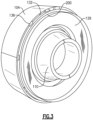
- Figure 3 shows the panel 104 and the exit 132.
- the firewall 126 is shown spaced from the outer panel 104 to provide the exhaust 132.
- Spacers 136 are positioned periodically circumferentially to maintain the exhaust 132 open.
- Element 200 is an inner seal land.
- a gas turbine engine under this disclosure could be said to include a propulsor delivering air into a core engine inward of an outer core panel.
- the core engine has a compressor section, a combustor and a turbine section.
- a compressor bleed system includes a bleed valve on a conduit communicating with compressed air from the compressor section. The bleed valve is configured to deliver air into a chamber where it can flow outwardly of the core engine at an exit location radially inward of the outer core panel.
Landscapes
- Engineering & Computer Science (AREA)
- Chemical & Material Sciences (AREA)
- Combustion & Propulsion (AREA)
- Mechanical Engineering (AREA)
- General Engineering & Computer Science (AREA)
- Physics & Mathematics (AREA)
- Fluid Mechanics (AREA)
- Structures Of Non-Positive Displacement Pumps (AREA)
Applications Claiming Priority (1)
| Application Number | Priority Date | Filing Date | Title |
|---|---|---|---|
| US18/305,252 US11927140B1 (en) | 2023-04-21 | 2023-04-21 | Gas turbine engine with guided bleed air dump |
Publications (1)
| Publication Number | Publication Date |
|---|---|
| EP4450797A1 true EP4450797A1 (de) | 2024-10-23 |
Family
ID=90184395
Family Applications (1)
| Application Number | Title | Priority Date | Filing Date |
|---|---|---|---|
| EP24171748.7A Pending EP4450797A1 (de) | 2023-04-21 | 2024-04-22 | Gasturbinenmotor mit geführter zapfluftentnahme |
Country Status (2)
| Country | Link |
|---|---|
| US (1) | US11927140B1 (de) |
| EP (1) | EP4450797A1 (de) |
Citations (5)
| Publication number | Priority date | Publication date | Assignee | Title |
|---|---|---|---|---|
| US20050106009A1 (en) * | 2003-11-13 | 2005-05-19 | Cummings Kevin J. | Bleed housing |
| CA2560448C (en) * | 2005-11-29 | 2014-11-18 | General Electric Company | Turbofan gas turbine engine with variable fan outlet guide vanes |
| US20150059315A1 (en) * | 2013-08-05 | 2015-03-05 | Rolls-Royce Deutschland Ltd & Co Kg | Apparatus and method for bleeding off compressor air in a jet engine |
| US20160123235A1 (en) * | 2014-10-16 | 2016-05-05 | Rolls-Royce Deutschland Ltd & Co Kg | Arrangement and method for blowing-off compressor air in a jet engine |
| US9909433B2 (en) * | 2012-04-10 | 2018-03-06 | Rolls-Royce Deutschland Ltd & Co Kg | Aircraft gas turbine having a booster bleed duct in a stator vane root element of a bypass duct |
Family Cites Families (10)
| Publication number | Priority date | Publication date | Assignee | Title |
|---|---|---|---|---|
| FR2912466A1 (fr) | 2007-02-12 | 2008-08-15 | Snecma Sa | Dispositif de decharge pour un turboreacteur,et turboreacteur le comportant |
| US9982598B2 (en) * | 2012-10-22 | 2018-05-29 | General Electric Company | Gas turbine engine variable bleed valve for ice extraction |
| US11473497B2 (en) | 2016-03-15 | 2022-10-18 | Hamilton Sundstrand Corporation | Engine bleed system with motorized compressor |
| FR3059365B1 (fr) * | 2016-11-25 | 2018-11-23 | Safran Aircraft Engines | Turbomachine a double flux equipee d'un systeme de decharge |
| US20190055889A1 (en) * | 2017-08-17 | 2019-02-21 | United Technologies Corporation | Ducted engine compressor bleed valve architecture |
| US11530650B2 (en) * | 2018-07-13 | 2022-12-20 | Raytheon Technologies Corporation | Gas turbine engine with active variable turbine cooling |
| US11261800B2 (en) * | 2018-10-24 | 2022-03-01 | Raytheon Technologies Corporation | Adaptive bleed schedule in a gas turbine engine |
| US11713722B2 (en) * | 2020-05-08 | 2023-08-01 | Rolls-Royce Corporation | Gas turbine engine compressor particulate offtake |
| US11970978B2 (en) * | 2021-06-25 | 2024-04-30 | Rohr, Inc. | Acoustic panel and method of forming same |
| US12410758B2 (en) * | 2022-01-10 | 2025-09-09 | General Electric Company | Three-stream gas turbine engine control |
-
2023
- 2023-04-21 US US18/305,252 patent/US11927140B1/en active Active
-
2024
- 2024-04-22 EP EP24171748.7A patent/EP4450797A1/de active Pending
Patent Citations (5)
| Publication number | Priority date | Publication date | Assignee | Title |
|---|---|---|---|---|
| US20050106009A1 (en) * | 2003-11-13 | 2005-05-19 | Cummings Kevin J. | Bleed housing |
| CA2560448C (en) * | 2005-11-29 | 2014-11-18 | General Electric Company | Turbofan gas turbine engine with variable fan outlet guide vanes |
| US9909433B2 (en) * | 2012-04-10 | 2018-03-06 | Rolls-Royce Deutschland Ltd & Co Kg | Aircraft gas turbine having a booster bleed duct in a stator vane root element of a bypass duct |
| US20150059315A1 (en) * | 2013-08-05 | 2015-03-05 | Rolls-Royce Deutschland Ltd & Co Kg | Apparatus and method for bleeding off compressor air in a jet engine |
| US20160123235A1 (en) * | 2014-10-16 | 2016-05-05 | Rolls-Royce Deutschland Ltd & Co Kg | Arrangement and method for blowing-off compressor air in a jet engine |
Also Published As
| Publication number | Publication date |
|---|---|
| US11927140B1 (en) | 2024-03-12 |
Similar Documents
| Publication | Publication Date | Title |
|---|---|---|
| US20200095929A1 (en) | High thrust geared gas turbine engine | |
| EP3808964B1 (de) | Getriebefan mit einem nicht epizyklischen untersetzungssystem | |
| US11608796B1 (en) | Radial strut frame connection between fan case and core housing in a gas turbine engine | |
| EP4123143A2 (de) | Kompressoranordnung für einen gasturbinenmotor | |
| EP4686822A1 (de) | Gasturbinenmotor mit kontrollierter rückführung von kraftstoff zum antrieb von zubehörteilen und nachrüstungsverfahren | |
| US20240240569A1 (en) | Gas turbine engine with idle thrust ratio | |
| EP4450797A1 (de) | Gasturbinenmotor mit geführter zapfluftentnahme | |
| EP4495402B1 (de) | Bifurkationsluftschaufel für gasturbinenmotor | |
| EP4509704A1 (de) | Gasturbinenmotor mit kerntrümmerschutz | |
| US12618363B2 (en) | Bifurcation air scoop for gas turbine engine | |
| US12378888B1 (en) | Airfoil-mounted acoustic resonator array for gas turbine engine component | |
| EP4123141A1 (de) | Gasturbinentriebwerk mit hohem leistungsausbeuteverhältnis bei niedrigem schieber | |
| EP4123142A1 (de) | Gasturbinenmotor mit höherem drehmoment-schub-verhältnis bei niedriger drehzahl | |
| EP4517064A1 (de) | Zweigang-planetengetriebe für umwandelbare motoren | |
| US12098681B2 (en) | High and low spool configuration for a gas turbine engine | |
| EP4180636A1 (de) | Radialstrebenrahmenverbindung zwischen fangehäuse und kerngehäuse in einem gasturbinenmotor | |
| EP4123155A1 (de) | Konfiguration mit hohem und niedrigem schieber für ein gasturbinentriebwerk | |
| EP4549701A1 (de) | Kombinierte gruppe von leitschaufel und äussere laufschaufelluftdichtung für gasturbinentriebwerk, und gasturbinentriebwerk | |
| EP4123148A1 (de) | Kompressoranordnung für einen gasturbinenmotor | |
| EP4502340A1 (de) | Leckagekontrolle für verdichterschaufeln eines gasturbinentriebwerks |
Legal Events
| Date | Code | Title | Description |
|---|---|---|---|
| PUAI | Public reference made under article 153(3) epc to a published international application that has entered the european phase |
Free format text: ORIGINAL CODE: 0009012 |
|
| STAA | Information on the status of an ep patent application or granted ep patent |
Free format text: STATUS: THE APPLICATION HAS BEEN PUBLISHED |
|
| AK | Designated contracting states |
Kind code of ref document: A1 Designated state(s): AL AT BE BG CH CY CZ DE DK EE ES FI FR GB GR HR HU IE IS IT LI LT LU LV MC ME MK MT NL NO PL PT RO RS SE SI SK SM TR |
|
| STAA | Information on the status of an ep patent application or granted ep patent |
Free format text: STATUS: REQUEST FOR EXAMINATION WAS MADE |
|
| 17P | Request for examination filed |
Effective date: 20250423 |