EP4450698A1 - Washing machine driving system and a washing machine with the same - Google Patents
Washing machine driving system and a washing machine with the same Download PDFInfo
- Publication number
- EP4450698A1 EP4450698A1 EP24159844.0A EP24159844A EP4450698A1 EP 4450698 A1 EP4450698 A1 EP 4450698A1 EP 24159844 A EP24159844 A EP 24159844A EP 4450698 A1 EP4450698 A1 EP 4450698A1
- Authority
- EP
- European Patent Office
- Prior art keywords
- shaft
- washing machine
- clutch
- bearing
- driving system
- Prior art date
- Legal status (The legal status is an assumption and is not a legal conclusion. Google has not performed a legal analysis and makes no representation as to the accuracy of the status listed.)
- Granted
Links
Images



Classifications
-
- F—MECHANICAL ENGINEERING; LIGHTING; HEATING; WEAPONS; BLASTING
- F16—ENGINEERING ELEMENTS AND UNITS; GENERAL MEASURES FOR PRODUCING AND MAINTAINING EFFECTIVE FUNCTIONING OF MACHINES OR INSTALLATIONS; THERMAL INSULATION IN GENERAL
- F16H—GEARING
- F16H3/00—Toothed gearings for conveying rotary motion with variable gear ratio or for reversing rotary motion
- F16H3/44—Toothed gearings for conveying rotary motion with variable gear ratio or for reversing rotary motion using gears having orbital motion
- F16H3/46—Gearings having only two central gears, connected by orbital gears
-
- D—TEXTILES; PAPER
- D06—TREATMENT OF TEXTILES OR THE LIKE; LAUNDERING; FLEXIBLE MATERIALS NOT OTHERWISE PROVIDED FOR
- D06F—LAUNDERING, DRYING, IRONING, PRESSING OR FOLDING TEXTILE ARTICLES
- D06F37/00—Details specific to washing machines covered by groups D06F21/00 - D06F25/00
- D06F37/30—Driving arrangements
- D06F37/36—Driving arrangements for rotating the receptacle at more than one speed
-
- D—TEXTILES; PAPER
- D06—TREATMENT OF TEXTILES OR THE LIKE; LAUNDERING; FLEXIBLE MATERIALS NOT OTHERWISE PROVIDED FOR
- D06F—LAUNDERING, DRYING, IRONING, PRESSING OR FOLDING TEXTILE ARTICLES
- D06F37/00—Details specific to washing machines covered by groups D06F21/00 - D06F25/00
- D06F37/30—Driving arrangements
- D06F37/304—Arrangements or adaptations of electric motors
-
- D—TEXTILES; PAPER
- D06—TREATMENT OF TEXTILES OR THE LIKE; LAUNDERING; FLEXIBLE MATERIALS NOT OTHERWISE PROVIDED FOR
- D06F—LAUNDERING, DRYING, IRONING, PRESSING OR FOLDING TEXTILE ARTICLES
- D06F37/00—Details specific to washing machines covered by groups D06F21/00 - D06F25/00
- D06F37/26—Casings; Tubs
- D06F37/261—Tubs made by a specially selected manufacturing process or characterised by their assembly from elements
- D06F37/263—Tubs made by a specially selected manufacturing process or characterised by their assembly from elements assembled from at least two elements connected to each other; Connecting or sealing means therefor
-
- D—TEXTILES; PAPER
- D06—TREATMENT OF TEXTILES OR THE LIKE; LAUNDERING; FLEXIBLE MATERIALS NOT OTHERWISE PROVIDED FOR
- D06F—LAUNDERING, DRYING, IRONING, PRESSING OR FOLDING TEXTILE ARTICLES
- D06F37/00—Details specific to washing machines covered by groups D06F21/00 - D06F25/00
- D06F37/26—Casings; Tubs
- D06F37/267—Tubs specially adapted for mounting thereto components or devices not provided for in preceding subgroups
- D06F37/269—Tubs specially adapted for mounting thereto components or devices not provided for in preceding subgroups for the bearing of the rotary receptacle
-
- F—MECHANICAL ENGINEERING; LIGHTING; HEATING; WEAPONS; BLASTING
- F16—ENGINEERING ELEMENTS AND UNITS; GENERAL MEASURES FOR PRODUCING AND MAINTAINING EFFECTIVE FUNCTIONING OF MACHINES OR INSTALLATIONS; THERMAL INSULATION IN GENERAL
- F16H—GEARING
- F16H57/00—General details of gearing
- F16H57/02—Gearboxes; Mounting gearing therein
- F16H57/021—Shaft support structures, e.g. partition walls, bearing eyes, casing walls or covers with bearings
-
- F—MECHANICAL ENGINEERING; LIGHTING; HEATING; WEAPONS; BLASTING
- F16—ENGINEERING ELEMENTS AND UNITS; GENERAL MEASURES FOR PRODUCING AND MAINTAINING EFFECTIVE FUNCTIONING OF MACHINES OR INSTALLATIONS; THERMAL INSULATION IN GENERAL
- F16H—GEARING
- F16H57/00—General details of gearing
- F16H57/08—General details of gearing of gearings with members having orbital motion
- F16H57/082—Planet carriers
-
- F—MECHANICAL ENGINEERING; LIGHTING; HEATING; WEAPONS; BLASTING
- F16—ENGINEERING ELEMENTS AND UNITS; GENERAL MEASURES FOR PRODUCING AND MAINTAINING EFFECTIVE FUNCTIONING OF MACHINES OR INSTALLATIONS; THERMAL INSULATION IN GENERAL
- F16H—GEARING
- F16H63/00—Control outputs from the control unit to change-speed- or reversing-gearings for conveying rotary motion or to other devices than the final output mechanism
- F16H63/02—Final output mechanisms therefor; Actuating means for the final output mechanisms
- F16H63/30—Constructional features of the final output mechanisms
- F16H63/304—Constructional features of the final output mechanisms the final output mechanisms comprising elements moved by electrical or magnetic force
-
- D—TEXTILES; PAPER
- D06—TREATMENT OF TEXTILES OR THE LIKE; LAUNDERING; FLEXIBLE MATERIALS NOT OTHERWISE PROVIDED FOR
- D06F—LAUNDERING, DRYING, IRONING, PRESSING OR FOLDING TEXTILE ARTICLES
- D06F23/00—Washing machines with receptacles, e.g. perforated, having a rotary movement, e.g. oscillatory movement, the receptacle serving both for washing and for centrifugally separating water from the laundry
- D06F23/02—Washing machines with receptacles, e.g. perforated, having a rotary movement, e.g. oscillatory movement, the receptacle serving both for washing and for centrifugally separating water from the laundry and rotating or oscillating about a horizontal axis
-
- F—MECHANICAL ENGINEERING; LIGHTING; HEATING; WEAPONS; BLASTING
- F16—ENGINEERING ELEMENTS AND UNITS; GENERAL MEASURES FOR PRODUCING AND MAINTAINING EFFECTIVE FUNCTIONING OF MACHINES OR INSTALLATIONS; THERMAL INSULATION IN GENERAL
- F16H—GEARING
- F16H57/00—General details of gearing
- F16H57/02—Gearboxes; Mounting gearing therein
- F16H2057/02034—Gearboxes combined or connected with electric machines
-
- F—MECHANICAL ENGINEERING; LIGHTING; HEATING; WEAPONS; BLASTING
- F16—ENGINEERING ELEMENTS AND UNITS; GENERAL MEASURES FOR PRODUCING AND MAINTAINING EFFECTIVE FUNCTIONING OF MACHINES OR INSTALLATIONS; THERMAL INSULATION IN GENERAL
- F16H—GEARING
- F16H57/00—General details of gearing
- F16H57/02—Gearboxes; Mounting gearing therein
- F16H2057/02039—Gearboxes for particular applications
- F16H2057/02069—Gearboxes for particular applications for industrial applications
- F16H2057/02073—Reduction gearboxes for industry
-
- F—MECHANICAL ENGINEERING; LIGHTING; HEATING; WEAPONS; BLASTING
- F16—ENGINEERING ELEMENTS AND UNITS; GENERAL MEASURES FOR PRODUCING AND MAINTAINING EFFECTIVE FUNCTIONING OF MACHINES OR INSTALLATIONS; THERMAL INSULATION IN GENERAL
- F16H—GEARING
- F16H57/00—General details of gearing
- F16H57/08—General details of gearing of gearings with members having orbital motion
- F16H2057/085—Bearings for orbital gears
-
- F—MECHANICAL ENGINEERING; LIGHTING; HEATING; WEAPONS; BLASTING
- F16—ENGINEERING ELEMENTS AND UNITS; GENERAL MEASURES FOR PRODUCING AND MAINTAINING EFFECTIVE FUNCTIONING OF MACHINES OR INSTALLATIONS; THERMAL INSULATION IN GENERAL
- F16H—GEARING
- F16H2200/00—Transmissions for multiple ratios
- F16H2200/003—Transmissions for multiple ratios characterised by the number of forward speeds
- F16H2200/0034—Transmissions for multiple ratios characterised by the number of forward speeds the gear ratios comprising two forward speeds
-
- F—MECHANICAL ENGINEERING; LIGHTING; HEATING; WEAPONS; BLASTING
- F16—ENGINEERING ELEMENTS AND UNITS; GENERAL MEASURES FOR PRODUCING AND MAINTAINING EFFECTIVE FUNCTIONING OF MACHINES OR INSTALLATIONS; THERMAL INSULATION IN GENERAL
- F16H—GEARING
- F16H2200/00—Transmissions for multiple ratios
- F16H2200/20—Transmissions using gears with orbital motion
- F16H2200/2002—Transmissions using gears with orbital motion characterised by the number of sets of orbital gears
- F16H2200/2005—Transmissions using gears with orbital motion characterised by the number of sets of orbital gears with one sets of orbital gears
-
- F—MECHANICAL ENGINEERING; LIGHTING; HEATING; WEAPONS; BLASTING
- F16—ENGINEERING ELEMENTS AND UNITS; GENERAL MEASURES FOR PRODUCING AND MAINTAINING EFFECTIVE FUNCTIONING OF MACHINES OR INSTALLATIONS; THERMAL INSULATION IN GENERAL
- F16H—GEARING
- F16H2200/00—Transmissions for multiple ratios
- F16H2200/20—Transmissions using gears with orbital motion
- F16H2200/2094—Transmissions using gears with orbital motion using positive clutches, e.g. dog clutches
Definitions
- the present disclosure relates to a washing machine driving system with a planetary gear assembly and a clutch assembly and a washing machine with the same.
- the washing machine is driven in two main operating modes with different operating conditions, for example, a washing mode (which may include a rinsing mode) and a spin-drying mode.
- a washing mode which may include a rinsing mode
- a spin-drying mode which may include a rinsing mode
- the washing machine is provided with a planetary gear assembly and a clutch assembly, and drives an drum shaft at low speed and high torque with a gear ratio of n: 1 (washing mode), or drives the drum shaft at high speed and low torque with a gear ratio of 1:1 (spin-drying mode).
- the drum shaft refers to a shaft coupled to a drum to rotate the drum.
- a washing mode (which may include a rinsing mode) is performed by operating the drum shaft at low speed and high torque, and after the washing mode ends, the motor is temporarily stopped, and a draining operation is performed. And, after the draining operation ends, a spin-drying mode starts.
- drum shaft must be operated at high speed and low torque in the spin-drying mode.
- the washing machine driving system includes parts for shifting a rotational force of the motor transmitted to the drum shaft between the washing mode and the spin-drying mode, for example, the planetary gear assembly and the clutch assembly.
- Korean Patent Publication No. KR10-2020-0106555 (hereinafter, referred to as "Related Art 1") and Korean Patent Publication No. KR10-2020-0089604 (hereinafter, referred to as "Related Art 2”) disclose a washing machine driving system in which the drum shaft is installed to pass through a carrier and a sun gear shaft of a planetary gear assembly.
- Korean Patent Publication No. KR10-2004-0065839 discloses a washing machine driving system in which a planetary gear assembly and a clutch assembly are arranged in series on an axis of a drum shaft.
- the washing machine driving system of the Related Art 3 has a problem that the volume of the drum is reduced due to the planetary gear assembly and the clutch assembly arranged in series on the shaft of the drum shaft.
- Korean Patent Registration Publication No. KR10-0210517 discloses a washing machine driving system formed by separating the sun gear of the planetary gear assembly from the drum shaft of the drum assembly.
- the washing machine driving system of the Related Art 4 has an inconvenience of having to fasten the drum shaft and the sun gear inside the drum assembly.
- a technical problem to be solved by the present disclosure is to provide a washing machine driving system capable of solving at least one of the above problems.
- Another technical problem to be solved by the present disclosure is to provide a washing machine driving system in which a drum shaft and the motor are separated, a planetary gear assembly is placed therebetween. According to the washing machine driving system, a size of a sun gear is not affected by a size of an outer diameter of a drum shaft.
- Still another technical problem to be solved by the present disclosure is to provide a washing machine driving system in which a carrier shaft is coupled to a back side end of the drum shaft, a coupling shaft is serration-coupled to the carrier shaft, and a second shaft portion of a carrier provided in the planetary gear assembly is serration-coupled to the coupling shaft.
- Still another technical problem to be solved by the present disclosure is to provide a washing machine driving system capable of effectively implementing a high reduction ratio region while having a compact size and using a small motor.
- Still another technical problem to be solved by the present disclosure is to provide a washing machine driving system capable of securing the volume of the drum to the maximum.
- Still another technical problem to be solved by the present disclosure is to provide a washing machine driving system capable of securing assembly efficiency.
- Still another technical problem to be solved by the present disclosure is to provide a washing machine driving system capable of minimizing a space required for the arrangement of the planetary gear assembly and the clutch assembly for manipulating it.
- Still another technical problem to be solved by the present disclosure is to provide a front-loading type washing machine having the above-mentioned washing machine driving system.
- a planetary gear assembly included in a washing machine driving system of the present disclosure may comprise a carrier shaft fixedly supported on a back end of a drum shaft by a first fastening member; a coupling shaft including a first shaft portion inserted into the carrier shaft and a first flange portion fixed to a back end of the carrier shaft by a second fastening member, and fixedly supported on the carrier shaft; a carrier including a second shaft portion inserted into the first shaft portion of the coupling shaft and a second flange portion positioned at a back side of the first flange portion of the coupling shaft, and fixedly supported on the coupling shaft; a sun gear rotationally supported on the coupling shaft and fixedly supported on a rotor frame of a motor by a third fastening member; a plurality of pinion gears coupled to the second flange portion of the carrier, and tooth-coupled with the sun gear; a ring gear tooth-coupled with the plurality of pinion gears; and a gear housing accommodating the sun gear, the
- tooth coupling refers to a state in which teeth of a gear portion provided in a corresponding gear are engaged with each other and coupled to each other.
- a carrier shaft which is unrelated to the reduction ratio of the planetary gear assembly, is fixedly supported on the drum shaft, and the sun gear, which is related to the reduction ratio of the planetary gear assembly, is rotationally supported on a coupling shaft that rotates integrally with the carrier shaft.
- the sun gear which is related to the reduction ratio of the planetary gear assembly, can be miniaturized, it is possible to compact the planetary gear assembly, and effectively implement a high reduction ratio region while using a small motor.
- the motor and the planetary gear assembly may be assembled and separated at the back side of the washing machine, so it is possible to improve assembly efficiency.
- the first fastening member may include a first head portion
- the third fastening member may include a second head portion
- the first head portion of the first fastening member and the second head portion of the third fastening member may face each other in an inner space of the carrier shaft.
- a front end of the sun gear may be spaced apart from the back end of the drum shaft in an axial direction.
- the size of the sun gear which is related to the reduction ratio of the planetary gear assembly, can be formed regardless of the size of the drum shaft, so that it is possible to downsize the sun gear, and accordingly, it is possible to downsize the planetary gear assembly.
- the washing machine driving system may further comprise a bearing assembly including a bearing housing in which the gear housing is fixedly supported; a clutch coupled to the gear housing to be slidable toward a front side and a back side along the axial direction of the drum shaft, and integrally rotating with the gear housing; and a clutch driving portion moving the clutch toward the front side or the back side.
- a bearing assembly including a bearing housing in which the gear housing is fixedly supported; a clutch coupled to the gear housing to be slidable toward a front side and a back side along the axial direction of the drum shaft, and integrally rotating with the gear housing; and a clutch driving portion moving the clutch toward the front side or the back side.
- the planetary gear assembly and the clutch may be positioned in an inner space formed by a stator provided in a motor.
- the planetary gear assembly and the clutch may be disposed in the inner space of the stator, it is possible to compact the washing machine driving system, and it is possible to secure the volume of the drum to the maximum.
- the bearing assembly may further include a first support bearing accommodated inside the bearing housing, the first support bearing may include a first bearing positioned between the bearing housing and the drum shaft to rotationally support the drum shaft, a second bearing positioned between the bearing housing and the carrier shaft to rotationally support the carrier shaft, and a third bearing positioned between the bearing housing and the gear housing to support the gear housing.
- the gear housing of the planetary gear assembly may be coupled to the bearing housing by the third bearing.
- the washing machine driving system may further comprise a second support bearing supporting the sun gear and the third fastening member, and the second support bearing may include a fourth bearing positioned between the coupling shaft and the sun gear, and a fifth bearing positioned between the gear housing and the sun gear.
- a front end of the second head portion of the third fastening member may be positioned forward a front end of the first shaft portion of the coupling shaft in the axial direction, and a forward movement of the fourth bearing in the axial direction may be restrained by the second head portion of the third fastening member.
- a back side end of the third fastening member may be fixed to the rotor frame by a fourth fastening member screwed to the third fastening member, and the third fastening member and the sun gear may rotate integrally with the rotor frame.
- the clutch may include a plurality of coupling protrusions at front side and back side ends, respectively, and the bearing housing and the rotor frame each may include a protrusion coupling portion coupled to the plurality of coupling protrusions when the clutch moves toward the front side or the back side.
- the clutch driving portion may include a clutch motor positioned in a direction perpendicular to the axial direction and coupled to the tub; a drawer coupled to the clutch motor and moving in a direction perpendicular to the axial direction by the clutch motor; a lifter including an arm portion in contact with a back side end of the clutch and moving in the axial direction according to the movement of the drawer; and a return spring positioned between the clutch and the gear housing and applying the clutch pressure toward the back side in the axial direction.
- a clutch link structure can be formed by simple linear motion of the drawer in a direction perpendicular to the axial direction within a narrow space between the motor and the planetary gear assembly, it is possible to minimize the installation space of the clutch driving portion.
- the clutch driving portion may further include a holder for supporting the drawer and the lifter.
- the drawer and the lifter each may include an inclined portion for moving the lifter in the axial direction according to the movement of the drawer.
- the lifter may include a guide, and a stator may include a guide insert portion into which the guide is inserted.
- the stator or the lifter may include a moment preventing portion for preventing rotational moment from being applied to the guide when the lifter moves in the axial direction.
- Each of the sun gear, the ring gear, and the plurality of pinion gears may include a helical gear.
- the washing machine according to the present disclosure may include a washing machine driving system having the above configuration.
- the drum shaft and the motor are separated, and the planetary gear assembly is disposed between the drum shaft and the motor, it is possible to form the size of the sun gear provided in the planetary gear assembly regardless of the size of the outer diameter of the drum shaft.
- the size of the sun gear can be reduced, it is possible to compact the planetary gear assembly.
- the volume of the drum can be secured as much as the size of the planetary gear assembly is reduced, it is possible to maximize the volume of the drum and improve the assembly efficiency.
- the coupling shaft is serration-coupled to the carrier shaft
- the second shaft portion of the carrier provided in the planetary gear assembly is serration-coupled to the coupling shaft
- the washing machine is a so-called drum type washing machine.
- this washing machine is a so-called full-automatic washing machine, and is configured to automatically execute a series of washing processes including processes such as washing, rinsing, and spin-drying.
- a washing machine may be composed of a main body, a tub 10 (fixed tank), a drum 20 (rotating tank), a washing machine driving system, a controller (control device), and the like.
- the controller may be composed of hardware such as a CPU and memory, and software such as a control program and various data.
- the controller may include at least one processor.
- the processor may be configured to execute program instructions maintained on memory.
- the main body of the washing machine is a box-shaped container composed of panels or frames, and may constitute an exterior of the washing machine.
- a circular inlet for putting in and taking out laundry may be formed on the front of the main body.
- a door having a transparent window may be installed in the inlet, and the inlet may be opened and closed by the door.
- An operation unit having a switch, etc. operated by a user may be installed on the upper side of the inlet in the main body.
- the tub 10 communicating with the inlet may be installed inside the main body.
- the tub 10 is made of a bottomed cylindrical container capable of storing water, and an opening of the tub 10 may communicate with the inlet.
- a water supply device including a water supply pipe, a water supply valve, and a detergent injection unit may be provided at the upper part of the tub 10.
- the drum 20 may be formed of a cylindrical container having a diameter slightly smaller than that of the tub 10, and may be accommodated in the tub 10 in a state in which the center line coincides with the tub 10.
- the drum 20 may have a circular opening corresponding to the inlet, and laundry may be put into the drum 20 through the inlet and the circular opening.
- a plurality of dewatering holes may be formed throughout the entire circumference of the drum 20.
- a driving system is installed on a back side of the tub 10.
- the back side means a side where a motor is positioned, and means the right side based on FIGS. 2 and 3 .
- a front side means a side where the tub 10 is positioned, and means the left side based on FIGS. 2 and 3 .
- the driving system may largely include a bearing assembly 100, a second bearing assembly 200, a planetary gear assembly 300, a clutch 400, a clutch driving portion 500, and a motor 600.
- the drum 20 may be fixed to a front side end of a drum shaft 25 protruding through the tub 10. Thus, the drum 20 may be driven in a direct driving manner.
- the bearing assembly 100 may be fixedly supported on the tub 10 toward the back side of the tub 10.
- the bearing assembly 100 may include a bearing housing 110 fixedly supported on the tub 10.
- the bearing housing 110 may have an inner space for accommodating the drum shaft 25.
- fixed support means that the tub 10 and the bearing assembly 100 are supported in a state in which relative rotation between them is impossible, that is, in a fixed state.
- the bearing assembly 100 may include a first support bearing 120 accommodated inside the bearing housing 110.
- the first support bearing 120 may include a first bearing 120a positioned between the bearing housing 110 and the drum shaft 25 to rotationally support the drum shaft 25, a second bearing 120b positioned between the bearing housing 110 and a carrier shaft 320 to rotationally support the carrier shaft 320, and a third bearing 120c positioned between the bearing housing 110 and a gear housing 350 to support the gear housing 350.
- rotationally support means that the drum shaft 25 is rotatably supported with respect to the bearing housing 110.
- the first support bearing 120 may effectively support the drum shaft 25 and the planetary gear assembly 300.
- the carrier shaft 320 may be fastened and supported by a first fastening member 311 at a back side end of the drum shaft 25, and the carrier shaft 320 may rotate integrally with the drum shaft 25.
- the first fastening member 311 may be formed of a screw inserted into an inner space of the carrier shaft 320 from a back side of the carrier shaft 320 and fastening the carrier shaft 320 to the drum shaft 25.
- a first head portion 311a of the first fastening member 311 may be positioned in the inner space of the carrier shaft 320.
- a front end of the carrier shaft 320 may be inserted into a back end of the drum shaft 25.
- a groove of a certain depth may be formed at the back end of the drum shaft 25, and a protrusion inserted into the groove of the drum shaft 25 may be provided at the front end of the carrier shaft 320.
- Splines or serrations may be provided on an inner circumferential surface of the groove formed at the back end of the drum shaft 25 and an outer circumferential surface of the protrusion formed at the front end of the carrier shaft 320, respectively.
- the carrier shaft 320 can be fixedly supported to the drum shaft 25 more reliably.
- the first fastening member may be omitted.
- a coupling shaft 330 may be fastened and fixedly supported at a back side end of the carrier shaft 320 by a second fastening member 313, and the coupling shaft 330 may rotate integrally with the carrier shaft 320.
- the coupling shaft 330 may include a first shaft portion 330a inserted into the carrier shaft 320, and a first flange portion 330b fixed to a back end of the carrier shaft 320 by the second fastening member 313.
- Splines or serrations may be provided on an outer circumferential surface of the first shaft portion 330a of the coupling shaft 330 and an inner circumferential surface of the carrier shaft 320 into which the first shaft portion 330a is inserted, respectively.
- the coupling shaft 330 can be fixedly supported to the carrier shaft 320 more reliably.
- the second fastening member 313 may be made of a screw.
- a carrier 340 may be coupled to and fixedly supported on the coupling shaft 330.
- the carrier 340 may include a second shaft portion 340a inserted into the first shaft portion 330a of the coupling shaft 330, and a second flange portion 340b positioned on a back side of the first flange portion 330b of the coupling shaft 330.
- Splines or serrations may be provided on a part of an outer circumferential surface of the second shaft portion 340a of the carrier 340 and an inner circumferential surface of the first shaft portion 330a of the coupling shaft 330, respectively.
- the carrier 340 can be fixedly supported to the coupling shaft 330 more reliably.
- the carrier 340 may rotate integrally with the coupling shaft 330, the carrier shaft 320 and the drum shaft 25.
- the planetary gear assembly 300 may further include the gear housing 350, a sun gear 360 accommodated inside the gear housing 350, a ring gear 370, and a plurality of pinion gears 380, in addition to the carrier shaft 320, the coupling shaft 330, and the carrier 340.
- the sun gear 360 may be rotationally supported on the coupling shaft 330 and fixedly supported on a rotor frame 610 of the motor 600 by a third fastening member 315.
- the third fastening member 315 may penetrate the sun gear 360 in an axial direction and may rotate integrally with the sun gear 360.
- the third fastening member 315 may be formed of a bolt.
- a second head portion 315a of the third fastening member 315 may be positioned in the inner space of the carrier shaft 320, and face the first head portion 311a of the first fastening member 311, and a front end of the second head part 315a may be positioned in front of a front end of the first shaft portion 330a of the coupling shaft 330.
- a front end of the sun gear 360 may be spaced apart from a back end of the first fastening member 311, that is, the first head portion 311a of the first fastening member 311.
- the front end of the sun gear 360 is spaced apart from the back end of the drum shaft 25 in the axial direction.
- the carrier shaft 320 is fixedly supported on the back end of the drum shaft 25
- the coupling shaft 330 is fixedly supported on the carrier shaft 320
- the third fastening member 315 and the sun gear 360 are rotationally supported on the coupling shaft 330.
- the sun gear 360 and the third fastening member 315 may be supported by a second support bearing 700.
- the second support bearing 700 may include a fourth bearing 710 positioned between the coupling shaft 330 and the sun gear 360, and a fifth bearing 720 positioned between the gear housing 350 and the sun gear 360.
- the first shaft portion 330a of the coupling shaft 330 may include a seating portion for seating the fourth bearing 710 thereon.
- the second head portion 315a of the third fastening member 315 may be in contact with the fourth bearing 710.
- a back end of the sun gear 360 may be coupled to the rotor frame 610 of the motor 600 by a fourth fastening member 317 screwed to a back end of the third fastening member 315.
- the ring gear 370 may be positioned on an inner wall of the gear housing 350, and may be fixedly supported on the gear housing 350.
- the plurality of pinion gears 380 may be coupled to the second flange portion 340b of the carrier 340.
- the plurality of pinion gears 380 coupled to the second flange portion 340b of the carrier 340 may rotate or revolve depending on whether the second flange portion 340b of the carrier 340 rotates in a state in which they are tooth-coupled to the sun gear 360 and the ring gear 370, respectively.
- tooth coupling refers to a state in which teeth of the gear portion provided in the corresponding gear are engaged with each other and coupled to each other.
- the plurality of pinion gears 380 each may rotate, but cannot revolve.
- the plurality of pinion gears 380 may revolve, or rotate and revolve.
- the gear housing 350 of the planetary gear assembly 300 may be coupled to the bearing housing 110 by the third bearing 120c.
- the planetary gear assembly 300 is limited in movement in the axial direction. Therefore, if the sun gear 360, the ring gear 370, and the plurality of pinion gears 380 each have a helical gear, the safety factor of the gears provided in the planetary gear assembly 300 can be increased, and the operating noise generated during gear rotation can reduced.
- the motor 600 may include the rotor frame 610 to which a back side end of the sun gear 330 is fixedly coupled, a stator 620 positioned in an inner space of the rotor frame 610, and a plurality of permanent magnets 630 positioned inside the rotor frame 610 and rotating the rotor frame 610 by interaction with the stator 620.
- the drum shaft 25 may rotate at low speed and high torque or at high speed and low torque, which will be described later.
- the rotor frame 610 has a space for accommodating the stator 620 and the plurality of permanent magnets 630 therein.
- the stator 620 disposed in the inner space of the rotor frame 610 may be fixed to the bearing housing 110 of the bearing assembly 100, and has an inner space accommodating the planetary gear assembly 300 .
- the planetary gear assembly 300 in particular, the gear housing 320 is positioned in the inner space formed by the stator 620.
- the clutch 400 for converting a power transmission path through the planetary gear assembly 300 may be positioned in the inner space formed by the stator 620.
- the clutch 400 may be coupled to the gear housing 320 to be slidable toward front side and the back side along the axial direction of the drum shaft.
- the clutch 400 is formed of two-stage bodies 400a and 400b having different diameters, and splines or serrations may be provided on an inner circumferential surface of a first body 400a having a relatively small diameter and an outer circumferential surface of the gear housing 320, respectively.
- a return spring 540 of the clutch driving portion 500 is positioned between the inside of a second body 400b having a relatively larger diameter than the first body 400a and the outer surface of the gear housing 320, and between the second body 400b and the outer surface of the second bearing housing 210.
- the clutch 400 may rotate integrally with the gear housing 320, and may move forward and backward along the axial direction.
- the clutch 400 may include a plurality of coupling protrusions 410 and 420 at front side end and back side end, respectively.
- the coupling protrusion 410 at the front side end may be formed at a front side end of the second body 400b, and the coupling protrusion 420 at the back side end may be formed at a back side end of the first body 400a.
- the bearing housing 110 may include a protrusion coupling portion 113 coupled to the plurality of coupling protrusions 410 when the clutch 400 moves forward along the axial direction
- the rotor frame 610 may include a protrusion coupling portion 613 coupled to the plurality of coupling protrusions 420 when the clutch 400 moves backward along the axial direction.
- the ring gear 340 is maintained in a fixed state, while the rotor frame 610 and the sun gear 330 rotate, the plurality of pinion gears 350 revolve around the sun gear 330 while rotating on their own, and the rotational force of the sun gear 330 is transmitted to the drum shaft 25 through the plurality of pinion gears 350 and the carrier 310 so that the drum shaft 25 is driven at low speed and high torque.
- the carrier 310 since the carrier 310 also rotates integrally with the gear housing 320, the rotational speed of the carrier 310 coincides with the rotational speed of the sun gear 330, and accordingly, the drum shaft 25 is driven at high speed and low torque.
- the clutch 400 since the power transmission path may be adjusted by coupling the clutch 400 to the bearing housing 110 or the rotor frame 610, the clutch 400 may move within a narrow space. Therefore, the installation space of the clutch 400 can be minimized.
- the washing machine drive system of the present disclosure further includes the clutch driving portion 500.
- the clutch driving portion 500 may include a clutch motor 510, a drawer 520, a lifter 530, and a return spring 540.
- the clutch motor 510 may be positioned in a direction perpendicular to the axial direction and may be coupled to the tub 10.
- the drawer 520 may be coupled to the clutch motor 510 and may move in the direction perpendicular to the axial direction by the clutch motor 510. When the drawer 520 is moved, a part of the drawer 520 may be positioned between a space between the rotor frame 610 and the tub 10.
- the lifter 530 has a C-type arm portion 531 that is in contact with a back side end of the clutch 400. It is also possible to have a ring-type arm portion instead of the C-type arm portion 531, and it is also possible to replace the C-type arm portion with another component capable of pressing the clutch 400 forward.
- the lifter 530 may move in the axial direction according to the movement of the drawer 520.
- the drawer 520 and the lifter 530 each may include an inclined portion 521 to allow the lifter 530 to move in the axial direction according to the movement of the drawer 520.
- the return spring 540 may be positioned inside the second body 400b of the clutch 400.
- the return spring 540 may be positioned between the clutch 400 and the gear housing 320 and between the clutch 400 and the second bearing housing 210, and press the clutch 400 toward the back side in the axial direction.
- a clutch link structure may be formed by simple linear motion of the drawer 520 in the direction perpendicular to the axial direction within a narrow space between the motor 600 and the planetary gear assembly 300, it is possible to minimize an installation space of the clutch driving portion 500.
- the clutch driving portion 500 may further include a holder 550 for supporting the drawer 520 and the lifter 530. According to this configuration, it is possible to effectively support the drawer 520 and the lifter 530 using the holder 550.
- the lifter 530 may include a guide 533, and the stator 620 may include a guide insertion portion 621 into which the guide 533 is inserted.
- stator 620 may include a moment preventing portion 623 for preventing rotational moment from being applied to the guide 533 when the lifter 530 moves in the axial direction.
- the moment preventing portion 623 is provided in the stator 620 as an example, but the moment preventing portion may be provided in the lifter 530.
- the coupling protrusion 420 of the clutch 400 separates from the protrusion coupling portion 613 of the rotor frame 610 and is separated from each other. Subsequently, when power is applied to the motor 600 to slowly rotate the rotor frame 610, while the coupling protrusion 410 of the clutch 400 is forwardly inserted into the protrusion coupling portion 113 formed on the bearing housing 110, the rotation of the ring gear 340 is restrained.
- the coupling protrusion 410 of the clutch 400 separates from the protrusion coupling portion 113 of the bearing housing 110 and is separated from each other. Subsequently, when power is applied to the motor 600 to slowly rotate the rotor frame 610, the coupling protrusion 420 of the clutch 400 has a rotational degree of freedom while being inserted into the protrusion coupling portion 613 of the rotor frame 610 by the spring force of the return spring 540, and the ring gear 340 has a degree of rotational freedom while being integrated with the rotor frame 610.
- the washing machine driving system of this configuration after inserting the drum assembly including the drum shaft 25 into the bearing housing 110 fixed to the tub 10, and inserting the carrier shaft 320 into the second bearing 120b, coupling the carrier shaft 320 to the drum shaft 25 using the first fastening member 311, inserting the fourth bearing 710 into the coupling shaft 330, coupling the coupling shaft 330 to the carrier shaft 320 using the second coupling member 313 while the third coupling member 315 is inserted into the coupling shaft 330, mounting the motor 600 on a back side of the planetary gear assembly 300, and fastening the fourth fastening member 317 to the third fastening member 315 may be performed sequentially.
- washing machine according to the present disclosure can maximize the volume of the drum.
Landscapes
- Engineering & Computer Science (AREA)
- General Engineering & Computer Science (AREA)
- Textile Engineering (AREA)
- Mechanical Engineering (AREA)
- Main Body Construction Of Washing Machines And Laundry Dryers (AREA)
Abstract
Description
- The present disclosure relates to a washing machine driving system with a planetary gear assembly and a clutch assembly and a washing machine with the same.
- The washing machine is driven in two main operating modes with different operating conditions, for example, a washing mode (which may include a rinsing mode) and a spin-drying mode.
- Therefore, in order to satisfy both of the above two main operating modes, the washing machine is provided with a planetary gear assembly and a clutch assembly, and drives an drum shaft at low speed and high torque with a gear ratio of n: 1 (washing mode), or drives the drum shaft at high speed and low torque with a gear ratio of 1:1 (spin-drying mode).
- Here, the drum shaft refers to a shaft coupled to a drum to rotate the drum.
- In the case of driving the drum shaft at low speed and high torque with a gear ratio of n: 1, it can be referred to as "deceleration mode", and in the case of driving the drum shaft at high speed and low torque with a gear ratio of 1: 1, it can be referred to as "direct connection mode".
- That is, in a normal washing machine, a washing mode (which may include a rinsing mode) is performed by operating the drum shaft at low speed and high torque, and after the washing mode ends, the motor is temporarily stopped, and a draining operation is performed. And, after the draining operation ends, a spin-drying mode starts.
- However, the drum shaft must be operated at high speed and low torque in the spin-drying mode.
- Therefore, the washing machine driving system includes parts for shifting a rotational force of the motor transmitted to the drum shaft between the washing mode and the spin-drying mode, for example, the planetary gear assembly and the clutch assembly.
- As an example of a related art related to the present disclosure, Korean Patent Publication No.
KR10-2020-0106555 KR10-2020-0089604 - However, since the diameter of the sun gear accommodating the drum shaft increases in the washing machine driving system of the Related Art 1 and Related Art 2, there is a problem that the reduction ratio is small.
- As another example of a related art related to the present disclosure, Korean Patent Publication No.
KR10-2004-0065839 - However, the washing machine driving system of the Related Art 3 has a problem that the volume of the drum is reduced due to the planetary gear assembly and the clutch assembly arranged in series on the shaft of the drum shaft.
- As still another example of a related art related to the present disclosure, Korean Patent Registration Publication No.
KR10-0210517 - However, the washing machine driving system of the Related Art 4 has an inconvenience of having to fasten the drum shaft and the sun gear inside the drum assembly.
-
- Related Art 1: Korean Patent Publication No.
KR 10-2020-0106555 - Related Art 2: Korean Patent Publication No.
KR 10-2020-0089604 - Related Art 3: Korean Patent Publication No.
KR 10-2004-0065839 - Related Art 4: Korean Patent Registration Publication No.
KR 10-0210517 - A technical problem to be solved by the present disclosure is to provide a washing machine driving system capable of solving at least one of the above problems.
- Another technical problem to be solved by the present disclosure is to provide a washing machine driving system in which a drum shaft and the motor are separated, a planetary gear assembly is placed therebetween. According to the washing machine driving system, a size of a sun gear is not affected by a size of an outer diameter of a drum shaft.
- Still another technical problem to be solved by the present disclosure is to provide a washing machine driving system in which a carrier shaft is coupled to a back side end of the drum shaft, a coupling shaft is serration-coupled to the carrier shaft, and a second shaft portion of a carrier provided in the planetary gear assembly is serration-coupled to the coupling shaft.
- Still another technical problem to be solved by the present disclosure is to provide a washing machine driving system capable of effectively implementing a high reduction ratio region while having a compact size and using a small motor.
- Still another technical problem to be solved by the present disclosure is to provide a washing machine driving system capable of securing the volume of the drum to the maximum.
- Still another technical problem to be solved by the present disclosure is to provide a washing machine driving system capable of securing assembly efficiency.
- Still another technical problem to be solved by the present disclosure is to provide a washing machine driving system capable of minimizing a space required for the arrangement of the planetary gear assembly and the clutch assembly for manipulating it.
- Still another technical problem to be solved by the present disclosure is to provide a front-loading type washing machine having the above-mentioned washing machine driving system.
- The technical problems to be achieved from the present disclosure are not limited to the technical problems mentioned above, and other technical problem which are not mentioned above can be clearly understood from the following description by those skilled in the art to which the present disclosure pertains.
- A planetary gear assembly included in a washing machine driving system of the present disclosure, may comprise a carrier shaft fixedly supported on a back end of a drum shaft by a first fastening member; a coupling shaft including a first shaft portion inserted into the carrier shaft and a first flange portion fixed to a back end of the carrier shaft by a second fastening member, and fixedly supported on the carrier shaft; a carrier including a second shaft portion inserted into the first shaft portion of the coupling shaft and a second flange portion positioned at a back side of the first flange portion of the coupling shaft, and fixedly supported on the coupling shaft; a sun gear rotationally supported on the coupling shaft and fixedly supported on a rotor frame of a motor by a third fastening member; a plurality of pinion gears coupled to the second flange portion of the carrier, and tooth-coupled with the sun gear; a ring gear tooth-coupled with the plurality of pinion gears; and a gear housing accommodating the sun gear, the plurality of pinion gears, and the ring gear therein.
- Here, "tooth coupling" refers to a state in which teeth of a gear portion provided in a corresponding gear are engaged with each other and coupled to each other.
- According to the washing machine driving system according to the present disclosure, a carrier shaft, which is unrelated to the reduction ratio of the planetary gear assembly, is fixedly supported on the drum shaft, and the sun gear, which is related to the reduction ratio of the planetary gear assembly, is rotationally supported on a coupling shaft that rotates integrally with the carrier shaft.
- Therefore, since the sun gear, which is related to the reduction ratio of the planetary gear assembly, can be miniaturized, it is possible to compact the planetary gear assembly, and effectively implement a high reduction ratio region while using a small motor.
- In addition, the motor and the planetary gear assembly may be assembled and separated at the back side of the washing machine, so it is possible to improve assembly efficiency.
- The first fastening member may include a first head portion, the third fastening member may include a second head portion, and the first head portion of the first fastening member and the second head portion of the third fastening member may face each other in an inner space of the carrier shaft.
- According to this configuration, since the first head portion of the first fastening member and the second head portion of the third fastening member are positioned in the inner space of the carrier shaft, it is possible to more compactly form the planetary gear assembly.
- A front end of the sun gear may be spaced apart from the back end of the drum shaft in an axial direction.
- Therefore, even if the outer diameter of the drum shaft is large, the size of the sun gear, which is related to the reduction ratio of the planetary gear assembly, can be formed regardless of the size of the drum shaft, so that it is possible to downsize the sun gear, and accordingly, it is possible to downsize the planetary gear assembly.
- The washing machine driving system according to the present disclosure, may further comprise a bearing assembly including a bearing housing in which the gear housing is fixedly supported; a clutch coupled to the gear housing to be slidable toward a front side and a back side along the axial direction of the drum shaft, and integrally rotating with the gear housing; and a clutch driving portion moving the clutch toward the front side or the back side.
- The planetary gear assembly and the clutch may be positioned in an inner space formed by a stator provided in a motor.
- According to the present disclosure, since the planetary gear assembly and the clutch may be disposed in the inner space of the stator, it is possible to compact the washing machine driving system, and it is possible to secure the volume of the drum to the maximum.
- The bearing assembly may further include a first support bearing accommodated inside the bearing housing, the first support bearing may include a first bearing positioned between the bearing housing and the drum shaft to rotationally support the drum shaft, a second bearing positioned between the bearing housing and the carrier shaft to rotationally support the carrier shaft, and a third bearing positioned between the bearing housing and the gear housing to support the gear housing.
- According to this configuration, it is possible to effectively support the drum shaft, the carrier shaft, and the gear housing.
- The gear housing of the planetary gear assembly may be coupled to the bearing housing by the third bearing.
- According to this configuration, it is possible to effectively support the gear housing.
- The washing machine driving system may further comprise a second support bearing supporting the sun gear and the third fastening member, and the second support bearing may include a fourth bearing positioned between the coupling shaft and the sun gear, and a fifth bearing positioned between the gear housing and the sun gear.
- A front end of the second head portion of the third fastening member may be positioned forward a front end of the first shaft portion of the coupling shaft in the axial direction, and a forward movement of the fourth bearing in the axial direction may be restrained by the second head portion of the third fastening member.
- According to this configuration, it is possible to effectively support the coupling shaft and the sun gear.
- A back side end of the third fastening member may be fixed to the rotor frame by a fourth fastening member screwed to the third fastening member, and the third fastening member and the sun gear may rotate integrally with the rotor frame.
- According to this configuration, it is possible to effectively assemble the planetary gear assembly and the motor at the back side of the washing machine.
- The clutch may include a plurality of coupling protrusions at front side and back side ends, respectively, and the bearing housing and the rotor frame each may include a protrusion coupling portion coupled to the plurality of coupling protrusions when the clutch moves toward the front side or the back side.
- According to this configuration, since the power transmission path can be adjusted by engaging the clutch with the bearing housing or the rotor frame, the installation space for the clutch can be minimized.
- The clutch driving portion may include a clutch motor positioned in a direction perpendicular to the axial direction and coupled to the tub; a drawer coupled to the clutch motor and moving in a direction perpendicular to the axial direction by the clutch motor; a lifter including an arm portion in contact with a back side end of the clutch and moving in the axial direction according to the movement of the drawer; and a return spring positioned between the clutch and the gear housing and applying the clutch pressure toward the back side in the axial direction.
- According to this configuration, since a clutch link structure can be formed by simple linear motion of the drawer in a direction perpendicular to the axial direction within a narrow space between the motor and the planetary gear assembly, it is possible to minimize the installation space of the clutch driving portion.
- The clutch driving portion may further include a holder for supporting the drawer and the lifter.
- According to this configuration, it is possible to effectively support the drawer and the lifter.
- The drawer and the lifter each may include an inclined portion for moving the lifter in the axial direction according to the movement of the drawer.
- According to this configuration, it is possible to effectively transmit the power of the clutch motor to the clutch.
- The lifter may include a guide, and a stator may include a guide insert portion into which the guide is inserted.
- According to this configuration, it is possible to effectively support the axial movement of the lifter.
- The stator or the lifter may include a moment preventing portion for preventing rotational moment from being applied to the guide when the lifter moves in the axial direction.
- According to this configuration, it is possible to effectively transmit the power of the clutch motor to the clutch.
- Each of the sun gear, the ring gear, and the plurality of pinion gears may include a helical gear.
- According to this configuration, it is possible to increase the safety factor of the gears provided in the planetary gear assembly, and reduce operating noise generated during gear rotation.
- The washing machine according to the present disclosure may include a washing machine driving system having the above configuration.
- Therefore, it is possible to maximize the volume of the drum and improve the assembly efficiency.
- According to the present disclosure, since the drum shaft and the motor are separated, and the planetary gear assembly is disposed between the drum shaft and the motor, it is possible to form the size of the sun gear provided in the planetary gear assembly regardless of the size of the outer diameter of the drum shaft.
- Therefore, since the size of the sun gear can be reduced, it is possible to compact the planetary gear assembly. In addition, it is possible to effectively implement a high reduction ratio region while using a small motor. Accordingly, it is possible to down-sizing the motor and motor driving circuit.
- In addition, since the volume of the drum can be secured as much as the size of the planetary gear assembly is reduced, it is possible to maximize the volume of the drum and improve the assembly efficiency.
- In addition, since the carrier shaft is coupled to the back side end of the drum shaft, the coupling shaft is serration-coupled to the carrier shaft, and the second shaft portion of the carrier provided in the planetary gear assembly is serration-coupled to the coupling shaft, it is possible to reliably fix and support the carrier shaft, the coupling shaft, and the second shaft portion of the carrier.
- In addition, it is possible to sufficiently secure the axial force necessary for moving the clutch even with a small-sized clutch motor.
- In addition, it is possible to increase the safety factor of the gears provided in the planetary gear assembly.
- In addition, it is possible to improve the durability and noise performance of the washing machine driving system and increase the driving efficiency.
- In addition, it is possible to improve the assembly efficiency of the washing machine driving system.
- Effects obtainable from the present disclosure are not limited by the effects mentioned above, and other effects which are not mentioned above can be clearly understood from the following description by those skilled in the art to which the present disclosure pertains.
- The accompanying drawings, which are included as a part of the detailed description to help the understanding of the present disclosure, provide embodiments of the present disclosure, and together with the detailed description, describe the technical features of the present disclosure.
-
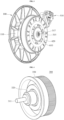
FIG. 1 is a perspective view showing a schematic configuration of a washing machine according to an embodiment of the present disclosure. -
FIG. 2 is a front side perspective view showing a schematic configuration of a washing machine driving system according to an embodiment of the present disclosure. -
FIG. 3 is a back side perspective view showing a schematic configuration of a washing machine driving system according to an embodiment of the present disclosure. -
FIG. 4 is a front side perspective view showing a schematic configuration of a planetary gear assembly provided in a washing machine driving system according to an embodiment of the present disclosure. -
FIG. 5 is a back side perspective view showing a schematic configuration of a planetary gear assembly provided in a washing machine driving system according to an embodiment of the present disclosure. -
FIG. 6 is a cross-sectional view showing a main part configuration when a washing machine driving system according to an embodiment of the present disclosure operates in a spin-drying mode. -
FIG. 7 is an enlarged cross-sectional view showing a main part configuration of a washing machine driving system according to an embodiment of the present disclosure. -
FIG. 8 is a cross-sectional view showing a main part configuration when a washing machine driving system according to an embodiment of the present disclosure operates in a washing mode. -
FIG. 9 is a perspective view showing a schematic configuration of a clutch and a clutch driving portion provided in a washing machine driving system according to an embodiment of the present disclosure. -
FIG. 10 is a cross-sectional perspective view showing a main part configuration when a washing machine driving system according to an embodiment of the present disclosure operates in a washing mode. -
FIG. 11 is a cross-sectional perspective view showing a detailed configuration of a clutch and a clutch driving portion provided in a washing machine driving system according to an embodiment of the present disclosure. - Hereinafter, embodiments disclosed in the present disclosure will be described in detail with reference to the accompanying drawings, however, regardless of the reference numerals, the same or similar components will be given the same reference numerals and redundant description thereof will be omitted.
- The suffixes "assembly" and "unit" for elements used in the following description are given or mixed in consideration of only the ease of writing the specification, and do not have distinct meanings or roles by themselves.
- In addition, in describing the embodiments disclosed in the present disclosure, when it is determined that the detailed description of the related known technology may obscure the subject matter of the embodiments disclosed in the present disclosure, the detailed description thereof will be omitted.
- In addition, the accompanying drawings are only for easily understanding the embodiments disclosed in the present disclosure, the technical disclosure is not limited by the accompanying drawings, and it should be understood that the accompanying drawings include all changes, equivalents, and substitutes included in the scope of the present disclosure.
- While terms, such as "first", "second", etc., may be used to describe various elements, such elements must not be limited by the above terms. The above terms are used only to distinguish one element from another.
- When an element is referred to as being "coupled" or "connected" to another element, it may be directly coupled to or connected to the other element, however, it should be understood that other elements may exist in the middle.
- On the other hand, when an element is referred to as being "directly coupled" or "directly assembled" to another element, it should be understood that there are no other elements in the middle.
- The singular forms are intended to include the plural forms as well, unless the context clearly indicates otherwise.
- In addition, in the present disclosure, it should be understood that the terms "comprise" and "have" specify the presence of stated features, integers, steps, operations, elements, parts, or combinations thereof, but do not preclude the presence or addition of one or more other features, integers, steps, operations, elements, parts, or combinations thereof.
- Hereinafter, a preferred embodiment according to the present disclosure will be described in detail with reference to the accompanying drawings, however, regardless of the reference numerals, the same or similar elements will be given the same reference numerals and redundant description thereof will be omitted.
- The washing machine according to an embodiment of the present disclosure is a so-called drum type washing machine. In addition, this washing machine is a so-called full-automatic washing machine, and is configured to automatically execute a series of washing processes including processes such as washing, rinsing, and spin-drying.
- As shown in
FIG. 1 , a washing machine according to the present disclosure may be composed of a main body, a tub 10 (fixed tank), a drum 20 (rotating tank), a washing machine driving system, a controller (control device), and the like. - The controller may be composed of hardware such as a CPU and memory, and software such as a control program and various data. The controller may include at least one processor. The processor may be configured to execute program instructions maintained on memory.
- The main body of the washing machine is a box-shaped container composed of panels or frames, and may constitute an exterior of the washing machine. A circular inlet for putting in and taking out laundry may be formed on the front of the main body.
- A door having a transparent window may be installed in the inlet, and the inlet may be opened and closed by the door.
- An operation unit having a switch, etc. operated by a user may be installed on the upper side of the inlet in the main body.
- The
tub 10 communicating with the inlet may be installed inside the main body. Thetub 10 is made of a bottomed cylindrical container capable of storing water, and an opening of thetub 10 may communicate with the inlet. - A water supply device including a water supply pipe, a water supply valve, and a detergent injection unit may be provided at the upper part of the
tub 10. - The
drum 20 may be formed of a cylindrical container having a diameter slightly smaller than that of thetub 10, and may be accommodated in thetub 10 in a state in which the center line coincides with thetub 10. - The
drum 20 may have a circular opening corresponding to the inlet, and laundry may be put into thedrum 20 through the inlet and the circular opening. A plurality of dewatering holes may be formed throughout the entire circumference of thedrum 20. - A driving system is installed on a back side of the
tub 10. Here, the back side means a side where a motor is positioned, and means the right side based onFIGS. 2 and3 . In addition, a front side means a side where thetub 10 is positioned, and means the left side based onFIGS. 2 and3 . - Referring to
FIGS. 2 to 6 , the driving system may largely include a bearingassembly 100, a second bearing assembly 200, aplanetary gear assembly 300, a clutch 400, a clutch driving portion 500, and amotor 600. - The
drum 20 may be fixed to a front side end of adrum shaft 25 protruding through thetub 10. Thus, thedrum 20 may be driven in a direct driving manner. - The bearing
assembly 100 may be fixedly supported on thetub 10 toward the back side of thetub 10. The bearingassembly 100 may include a bearinghousing 110 fixedly supported on thetub 10. The bearinghousing 110 may have an inner space for accommodating thedrum shaft 25. - Here, "fixed support" means that the
tub 10 and the bearingassembly 100 are supported in a state in which relative rotation between them is impossible, that is, in a fixed state. - The bearing
assembly 100 may include a first support bearing 120 accommodated inside the bearinghousing 110. - The first support bearing 120 may include a
first bearing 120a positioned between the bearinghousing 110 and thedrum shaft 25 to rotationally support thedrum shaft 25, asecond bearing 120b positioned between the bearinghousing 110 and acarrier shaft 320 to rotationally support thecarrier shaft 320, and athird bearing 120c positioned between the bearinghousing 110 and agear housing 350 to support thegear housing 350. - Here, "rotationally support" means that the
drum shaft 25 is rotatably supported with respect to the bearinghousing 110. - Therefore, the first support bearing 120 may effectively support the
drum shaft 25 and theplanetary gear assembly 300. - The
carrier shaft 320 may be fastened and supported by afirst fastening member 311 at a back side end of thedrum shaft 25, and thecarrier shaft 320 may rotate integrally with thedrum shaft 25. - The
first fastening member 311 may be formed of a screw inserted into an inner space of thecarrier shaft 320 from a back side of thecarrier shaft 320 and fastening thecarrier shaft 320 to thedrum shaft 25. - A
first head portion 311a of thefirst fastening member 311 may be positioned in the inner space of thecarrier shaft 320. - A front end of the
carrier shaft 320 may be inserted into a back end of thedrum shaft 25. - To this end, a groove of a certain depth may be formed at the back end of the
drum shaft 25, and a protrusion inserted into the groove of thedrum shaft 25 may be provided at the front end of thecarrier shaft 320. - Splines or serrations may be provided on an inner circumferential surface of the groove formed at the back end of the
drum shaft 25 and an outer circumferential surface of the protrusion formed at the front end of thecarrier shaft 320, respectively. - According to this configuration, the
carrier shaft 320 can be fixedly supported to thedrum shaft 25 more reliably. - In addition, when splines or serrations each are formed on the inner circumferential surface of the groove formed at the back end of the
drum shaft 25 and the outer circumferential surface of the protrusion formed at the front end of thecarrier shaft 320, optionally, the first fastening member may be omitted. - A
coupling shaft 330 may be fastened and fixedly supported at a back side end of thecarrier shaft 320 by asecond fastening member 313, and thecoupling shaft 330 may rotate integrally with thecarrier shaft 320. - The
coupling shaft 330 may include afirst shaft portion 330a inserted into thecarrier shaft 320, and afirst flange portion 330b fixed to a back end of thecarrier shaft 320 by thesecond fastening member 313. - Splines or serrations may be provided on an outer circumferential surface of the
first shaft portion 330a of thecoupling shaft 330 and an inner circumferential surface of thecarrier shaft 320 into which thefirst shaft portion 330a is inserted, respectively. - According to this configuration, the
coupling shaft 330 can be fixedly supported to thecarrier shaft 320 more reliably. - The
second fastening member 313 may be made of a screw. - A
carrier 340 may be coupled to and fixedly supported on thecoupling shaft 330. - The
carrier 340 may include asecond shaft portion 340a inserted into thefirst shaft portion 330a of thecoupling shaft 330, and asecond flange portion 340b positioned on a back side of thefirst flange portion 330b of thecoupling shaft 330. - Splines or serrations may be provided on a part of an outer circumferential surface of the
second shaft portion 340a of thecarrier 340 and an inner circumferential surface of thefirst shaft portion 330a of thecoupling shaft 330, respectively. - According to this configuration, the
carrier 340 can be fixedly supported to thecoupling shaft 330 more reliably. - The
carrier 340 may rotate integrally with thecoupling shaft 330, thecarrier shaft 320 and thedrum shaft 25. - The
planetary gear assembly 300 may further include thegear housing 350, asun gear 360 accommodated inside thegear housing 350, aring gear 370, and a plurality of pinion gears 380, in addition to thecarrier shaft 320, thecoupling shaft 330, and thecarrier 340. - The
sun gear 360 may be rotationally supported on thecoupling shaft 330 and fixedly supported on arotor frame 610 of themotor 600 by athird fastening member 315. - The
third fastening member 315 may penetrate thesun gear 360 in an axial direction and may rotate integrally with thesun gear 360. Thethird fastening member 315 may be formed of a bolt. - A
second head portion 315a of thethird fastening member 315 may be positioned in the inner space of thecarrier shaft 320, and face thefirst head portion 311a of thefirst fastening member 311, and a front end of thesecond head part 315a may be positioned in front of a front end of thefirst shaft portion 330a of thecoupling shaft 330. - When the
sun gear 360 is coupled to thecoupling shaft 330 using thethird fastening member 315, since themotor 600 and theplanetary gear assembly 300 may be assembled and separated on the back side for easy visibility, assembly efficiency can be improved. - In the inner space of the
carrier shaft 320, a front end of thesun gear 360 may be spaced apart from a back end of thefirst fastening member 311, that is, thefirst head portion 311a of thefirst fastening member 311. - Therefore, the front end of the
sun gear 360 is spaced apart from the back end of thedrum shaft 25 in the axial direction. - Specifically, the
carrier shaft 320 is fixedly supported on the back end of thedrum shaft 25, thecoupling shaft 330 is fixedly supported on thecarrier shaft 320, and thethird fastening member 315 and thesun gear 360 are rotationally supported on thecoupling shaft 330. - In this way, since the front end of the
sun gear 360 is spaced apart from the back end of thedrum shaft 25, it is possible to downsize thesun gear 360 related to the reduction ratio of theplanetary gear assembly 300. - Therefore, it is possible to compact the
planetary gear assembly 300, and it is possible to effectively implement a high reduction ratio region while using a small motor. - The
sun gear 360 and thethird fastening member 315 may be supported by a second support bearing 700. - The second support bearing 700 may include a
fourth bearing 710 positioned between thecoupling shaft 330 and thesun gear 360, and afifth bearing 720 positioned between thegear housing 350 and thesun gear 360. - The
first shaft portion 330a of thecoupling shaft 330 may include a seating portion for seating thefourth bearing 710 thereon. - The
second head portion 315a of thethird fastening member 315 may be in contact with thefourth bearing 710. - A back end of the
sun gear 360 may be coupled to therotor frame 610 of themotor 600 by afourth fastening member 317 screwed to a back end of thethird fastening member 315. - The
ring gear 370 may be positioned on an inner wall of thegear housing 350, and may be fixedly supported on thegear housing 350. - The plurality of pinion gears 380 may be coupled to the
second flange portion 340b of thecarrier 340. - The plurality of pinion gears 380 coupled to the
second flange portion 340b of thecarrier 340 may rotate or revolve depending on whether thesecond flange portion 340b of thecarrier 340 rotates in a state in which they are tooth-coupled to thesun gear 360 and thering gear 370, respectively. - Here, "tooth coupling" refers to a state in which teeth of the gear portion provided in the corresponding gear are engaged with each other and coupled to each other.
- For example, in a state in which the
second flange 340b of thecarrier 340 is fixed, the plurality of pinion gears 380 each may rotate, but cannot revolve. In addition, in a state in which thesecond flange portion 340b of thecarrier 340 rotates, the plurality of pinion gears 380 may revolve, or rotate and revolve. - The
gear housing 350 of theplanetary gear assembly 300 may be coupled to the bearinghousing 110 by thethird bearing 120c. - According to this configuration, the
planetary gear assembly 300 is limited in movement in the axial direction. Therefore, if thesun gear 360, thering gear 370, and the plurality of pinion gears 380 each have a helical gear, the safety factor of the gears provided in theplanetary gear assembly 300 can be increased, and the operating noise generated during gear rotation can reduced. - The
motor 600 may include therotor frame 610 to which a back side end of thesun gear 330 is fixedly coupled, astator 620 positioned in an inner space of therotor frame 610, and a plurality ofpermanent magnets 630 positioned inside therotor frame 610 and rotating therotor frame 610 by interaction with thestator 620. - Therefore, when the
motor 600 operates and therotor frame 610 rotates, thesun gear 330 fixed to therotor frame 610 rotates, and the drum shaft rotates according to the rotation of thesun gear 330. - At this time, the
drum shaft 25 may rotate at low speed and high torque or at high speed and low torque, which will be described later. - The
rotor frame 610 has a space for accommodating thestator 620 and the plurality ofpermanent magnets 630 therein. - The
stator 620 disposed in the inner space of therotor frame 610 may be fixed to the bearinghousing 110 of the bearingassembly 100, and has an inner space accommodating theplanetary gear assembly 300 . - That is, the
planetary gear assembly 300, in particular, thegear housing 320 is positioned in the inner space formed by thestator 620. - The clutch 400 for converting a power transmission path through the
planetary gear assembly 300 may be positioned in the inner space formed by thestator 620. - That is, the clutch 400 may be coupled to the
gear housing 320 to be slidable toward front side and the back side along the axial direction of the drum shaft. - Referring to
FIGS. 9 to 11 , the clutch 400 is formed of two-stage bodies first body 400a having a relatively small diameter and an outer circumferential surface of thegear housing 320, respectively. - In addition, a
return spring 540 of the clutch driving portion 500 is positioned between the inside of asecond body 400b having a relatively larger diameter than thefirst body 400a and the outer surface of thegear housing 320, and between thesecond body 400b and the outer surface of the second bearing housing 210. - Therefore, the clutch 400 may rotate integrally with the
gear housing 320, and may move forward and backward along the axial direction. - The clutch 400 may include a plurality of
coupling protrusions - The
coupling protrusion 410 at the front side end may be formed at a front side end of thesecond body 400b, and thecoupling protrusion 420 at the back side end may be formed at a back side end of thefirst body 400a. - The bearing
housing 110 may include aprotrusion coupling portion 113 coupled to the plurality ofcoupling protrusions 410 when the clutch 400 moves forward along the axial direction, and therotor frame 610 may include aprotrusion coupling portion 613 coupled to the plurality ofcoupling protrusions 420 when the clutch 400 moves backward along the axial direction. - A method of driving the washing machine having the driving system according to this configuration will be described with reference to
FIGS. 2 and3 . - When the clutch 400 moves forward and the
coupling protrusion 410 at the front side end of the clutch 400 is coupled to theprotrusion coupling portion 113 of the bearinghousing 110 as shown inFIG. 3 , rotation of thegear housing 320 to which the clutch 400 is coupled is restrained. - That is, since the bearing
housing 110 is fixed to thetub 10, rotations of the bearinghousing 110, the clutch 400 coupled to the bearinghousing 110, and thegear housing 320 coupled to the clutch 400 are restrained. - Therefore, since the
ring gear 340 is maintained in a fixed state, while therotor frame 610 and thesun gear 330 rotate, the plurality of pinion gears 350 revolve around thesun gear 330 while rotating on their own, and the rotational force of thesun gear 330 is transmitted to thedrum shaft 25 through the plurality of pinion gears 350 and the carrier 310 so that thedrum shaft 25 is driven at low speed and high torque. - Then, when the clutch 400 moves to the back side and the
coupling protrusion 420 of the clutch 400 is coupled to theprotrusion coupling portion 613 of therotor frame 610, thesun gear 330, the clutch 400, and thegear housing 320 to which the clutch 400 is coupled rotate integrally while therotor frame 610 rotates. - Therefore, since the carrier 310 also rotates integrally with the
gear housing 320, the rotational speed of the carrier 310 coincides with the rotational speed of thesun gear 330, and accordingly, thedrum shaft 25 is driven at high speed and low torque. - According to this configuration, since the power transmission path may be adjusted by coupling the clutch 400 to the bearing
housing 110 or therotor frame 610, the clutch 400 may move within a narrow space. Therefore, the installation space of the clutch 400 can be minimized. - Since the
planetary gear assembly 300 and the clutch 400 are disposed in the inner space of thestator 620, it is possible to compact the washing machine driving system and secure the maximum volume of thedrum 20. - In order to be able to adjust the power transmission path by changing the position of the clutch 400 as described above, the washing machine drive system of the present disclosure further includes the clutch driving portion 500.
- The clutch driving portion 500 may include a
clutch motor 510, adrawer 520, alifter 530, and areturn spring 540. - The
clutch motor 510 may be positioned in a direction perpendicular to the axial direction and may be coupled to thetub 10. - The
drawer 520 may be coupled to theclutch motor 510 and may move in the direction perpendicular to the axial direction by theclutch motor 510. When thedrawer 520 is moved, a part of thedrawer 520 may be positioned between a space between therotor frame 610 and thetub 10. - The
lifter 530 has a C-type arm portion 531 that is in contact with a back side end of the clutch 400. It is also possible to have a ring-type arm portion instead of the C-type arm portion 531, and it is also possible to replace the C-type arm portion with another component capable of pressing the clutch 400 forward. - The
lifter 530 may move in the axial direction according to the movement of thedrawer 520. - To this end, the
drawer 520 and thelifter 530 each may include aninclined portion 521 to allow thelifter 530 to move in the axial direction according to the movement of thedrawer 520. - According to this configuration, it is possible to effectively transmit the power of the
clutch motor 510 to the clutch 400. - The
return spring 540 may be positioned inside thesecond body 400b of the clutch 400. - Therefore, the
return spring 540 may be positioned between the clutch 400 and thegear housing 320 and between the clutch 400 and the second bearing housing 210, and press the clutch 400 toward the back side in the axial direction. - According to this configuration, since a clutch link structure may be formed by simple linear motion of the
drawer 520 in the direction perpendicular to the axial direction within a narrow space between themotor 600 and theplanetary gear assembly 300, it is possible to minimize an installation space of the clutch driving portion 500. - The clutch driving portion 500 may further include a
holder 550 for supporting thedrawer 520 and thelifter 530. According to this configuration, it is possible to effectively support thedrawer 520 and thelifter 530 using theholder 550. - The
lifter 530 may include aguide 533, and thestator 620 may include aguide insertion portion 621 into which theguide 533 is inserted. - According to this configuration, it is possible to effectively support the axial movement of the
lifter 530. - In addition, the
stator 620 may include amoment preventing portion 623 for preventing rotational moment from being applied to theguide 533 when thelifter 530 moves in the axial direction. - In the above, it has been described that the
moment preventing portion 623 is provided in thestator 620 as an example, but the moment preventing portion may be provided in thelifter 530. - According to this configuration, it is possible to effectively prevent malfunction of the lifter, and it is possible to effectively transmit the power of the
clutch motor 510 to the clutch 400. - According to this configuration, when the
clutch motor 510 operates to pull thedrawer 520 in the deceleration mode, thelifter 530 moves forward along theinclined portion 521 of thedrawer 520, and the C-type arm portion 531 of thelifter 530 presses the clutch 400 forward, and accordingly, thereturn spring 540 mounted inside the clutch 400 in a compressed state is further compressed. - Then, the
coupling protrusion 420 of the clutch 400 separates from theprotrusion coupling portion 613 of therotor frame 610 and is separated from each other. Subsequently, when power is applied to themotor 600 to slowly rotate therotor frame 610, while thecoupling protrusion 410 of the clutch 400 is forwardly inserted into theprotrusion coupling portion 113 formed on the bearinghousing 110, the rotation of thering gear 340 is restrained. - In addition, in the direct connection mode, when the
clutch motor 510 pushes thedrawer 520, thelifter 530 moves rearward along theinclined portion 521 of thedrawer 520 and thereturn spring 540 mounted inside the clutch 400 in a compressed state becomes less compressed. - Then, the
coupling protrusion 410 of the clutch 400 separates from theprotrusion coupling portion 113 of the bearinghousing 110 and is separated from each other. Subsequently, when power is applied to themotor 600 to slowly rotate therotor frame 610, thecoupling protrusion 420 of the clutch 400 has a rotational degree of freedom while being inserted into theprotrusion coupling portion 613 of therotor frame 610 by the spring force of thereturn spring 540, and thering gear 340 has a degree of rotational freedom while being integrated with therotor frame 610. - According to the washing machine driving system of this configuration, after inserting the drum assembly including the
drum shaft 25 into the bearinghousing 110 fixed to thetub 10, and inserting thecarrier shaft 320 into thesecond bearing 120b, coupling thecarrier shaft 320 to thedrum shaft 25 using thefirst fastening member 311, inserting thefourth bearing 710 into thecoupling shaft 330, coupling thecoupling shaft 330 to thecarrier shaft 320 using thesecond coupling member 313 while thethird coupling member 315 is inserted into thecoupling shaft 330, mounting themotor 600 on a back side of theplanetary gear assembly 300, and fastening thefourth fastening member 317 to thethird fastening member 315 may be performed sequentially. Thus, it is possible to complete the installation of theplanetary gear assembly 300 and themotor 600 by sequentially performing the above operations. - Therefore, since it is possible to assemble the planetary gear assembly and the motor on the back side for easy visibility, the assembly efficiency can be improved.
- In addition, the washing machine according to the present disclosure can maximize the volume of the drum.
- It is apparent to those skilled in the art that the present disclosure may be embodied in other specific forms without departing from the essential characteristics of the present disclosure. Accordingly, the above detailed description should not be construed as restrictive in all respects but should be considered as illustrative. The scope of the present disclosure should be determined by reasonable interpretation of the appended claims, and all changes within the equivalent scope of the present disclosure are included in the scope of the present disclosure.
Claims (15)
- A washing machine driving system comprising a planetary gear assembly (300) comprising:a carrier shaft (320) fixedly supported on a back end of a drum shaft (25) by a first fastening member (311);a coupling shaft (330) including a first shaft portion (330a) inserted into the carrier shaft (320) and a first flange portion (330b) fixed to a back end of the carrier shaft (320) by a second fastening member (313), and fixedly supported on the carrier shaft (320);a carrier (340) including a second shaft portion (340a) inserted into the first shaft portion (330a) of the coupling shaft (330) and a second flange portion (340b) positioned at a back side of the first flange portion (330b) of the coupling shaft (330), and fixedly supported on the coupling shaft (330);a sun gear (360) rotationally supported on the coupling shaft (330) and fixedly supported on a rotor frame (610) of a motor (600) by a third fastening member (315);a plurality of pinion gears (380) coupled to the second flange portion (340b) of the carrier (340), and tooth-coupled with the sun gear (360);a ring gear (370) tooth-coupled with the plurality of pinion gears (380); anda gear housing (350) accommodating the sun gear (360), the plurality of pinion gears (380), and the ring gear (370) therein.
- The washing machine driving system of claim 1, wherein the first fastening member (311) includes a first head portion (311a), the third fastening member (315) includes a second head portion (315a), and the first head portion (311a) of the first fastening member (311) and the second head portion (315a) of the third fastening member (315) face each other in an inner space of the carrier shaft (320).
- The washing machine driving system of claim 2, wherein a front end of the sun gear (360) is spaced apart from the back end of the drum shaft (25) in an axial direction.
- The washing machine driving system of claim 2 or 3, further comprising:
a bearing assembly (100) including a bearing housing (110) in which the gear housing (350) is fixedly supported. - The washing machine driving system of any one of the preceding claims, further comprising a clutch (400) coupled to the gear housing (350) to be slidable toward a front side and a back side along the axial direction of the drum shaft (25), and integrally rotating with the gear housing (350); and
a clutch driving portion (500) moving the clutch (400) toward the front side or the back side. - The washing machine driving system of claim 5, wherein the bearing assembly (100) further includes a first support bearing (120) accommodated inside the bearing housing (110).
- The washing machine driving system of claim 6, wherein the first support bearing (120) includes a first bearing (120a) positioned between the bearing housing (110) and the drum shaft (25) to rotationally support the drum shaft (25), a second bearing (120b) positioned between the bearing housing (110) and the carrier shaft (320) to rotationally support the carrier shaft (320), and a third bearing (120c) positioned between the bearing housing (110) and the gear housing (350) to support the gear housing (350).
- The washing machine driving system of claim 7, wherein the gear housing (350) of the planetary gear assembly (300) is coupled to the bearing housing (110) by the third bearing (120c).
- The washing machine driving system of claim 7 or 8, further comprising:a second support bearing (700) supporting the sun gear (360) and the third fastening member (315),wherein the second support bearing (700) includes a fourth bearing (710) positioned between the coupling shaft (330) and the sun gear (360), and a fifth bearing (720) positioned between the gear housing (350) and the sun gear (360).
- The washing machine driving system of claim 9, wherein a front end of the second head portion (315a) of the third fastening member (315) is positioned forward a front end of the first shaft portion (330a) of the coupling shaft (330) in the axial direction, and a forward movement of the fourth bearing (710) in the axial direction is restrained by the second head portion (315a) of the third fastening member (315).
- The washing machine driving system of any one of claims 7 to 10, wherein a back side end of the third fastening member (315) is fixed to the rotor frame (610) by a fourth fastening member (317) screwed to the third fastening member (315), and the third fastening member (315) and the sun gear (360) rotate integrally with the rotor frame (610).
- The washing machine driving system of claim 11, wherein the clutch (400) includes a plurality of coupling protrusions (410, 420) at front and back ends, respectively, and
the bearing housing (110), and the rotor frame (610) provided in the motor (600) each include a protrusion coupling portion (113, 613) coupled to the plurality of coupling protrusions (410, 420) when the clutch (400) moves toward the front side or the back side. - The washing machine driving system of claim 12, wherein the clutch driving portion (500) includes:a clutch motor (510) positioned in a direction perpendicular to the axial direction, and coupled to a tub (10);a drawer (520) coupled to the clutch motor (510), and moving in a direction perpendicular to the axial direction by the clutch motor (510);a lifter (530) including an arm portion (531) in contact with a back side end of the clutch (400), and moving in the axial direction according to the movement of the drawer (520); anda return spring (540) positioned between the clutch (400) and the gear housing (350), and applying the clutch (400) pressure toward the back side in the axial direction.
- The washing machine driving system of claim 13, wherein the clutch driving portion (500) further includes a holder (550) for supporting the drawer (520) and the lifter (530), orwherein the drawer (520) and the lifter (530) each include an inclined portion (521) for moving the lifter (530) in the axial direction according to the movement of the drawer (520), orwherein the lifter (530) includes a guide (533), and a stator (620) includes a guide insert portion (621) into which the guide (533) is inserted, orwherein the stator (620) or the lifter (530) includes a moment preventing portion (623) for preventing rotational moment from being applied to the guide (533) when the lifter (530) moves in the axial direction.
- A washing machine including the washing machine driving system of any one of claims 1 to 14.
Applications Claiming Priority (1)
| Application Number | Priority Date | Filing Date | Title |
|---|---|---|---|
| KR1020230051727A KR102903077B1 (en) | 2023-04-20 | 2023-04-20 | Washing machine driving system and a washing machine with the same |
Publications (2)
| Publication Number | Publication Date |
|---|---|
| EP4450698A1 true EP4450698A1 (en) | 2024-10-23 |
| EP4450698B1 EP4450698B1 (en) | 2025-05-28 |
Family
ID=90097610
Family Applications (1)
| Application Number | Title | Priority Date | Filing Date |
|---|---|---|---|
| EP24159844.0A Active EP4450698B1 (en) | 2023-04-20 | 2024-02-27 | Washing machine driving system and a washing machine with the same |
Country Status (3)
| Country | Link |
|---|---|
| US (1) | US12181028B2 (en) |
| EP (1) | EP4450698B1 (en) |
| KR (1) | KR102903077B1 (en) |
Citations (7)
| Publication number | Priority date | Publication date | Assignee | Title |
|---|---|---|---|---|
| GB991437A (en) * | 1961-01-17 | 1965-05-05 | Fichtel & Sachs Ag | Gear for washing machines |
| KR100210517B1 (en) | 1992-05-16 | 1999-07-15 | 구자홍 | Clutch structure of washing machine |
| KR20040065839A (en) | 2003-01-16 | 2004-07-23 | 엘지전자 주식회사 | Drum type washing machine with induction motor |
| CN203923701U (en) * | 2014-03-17 | 2014-11-05 | 安徽聚隆传动科技股份有限公司 | A kind of roller washing machine speed-reducing clutch and washing machine thereof |
| US20170096765A1 (en) * | 2015-10-02 | 2017-04-06 | Lg Electronics Inc. | Top-loading type washing machine |
| KR20200089604A (en) | 2019-01-17 | 2020-07-27 | 삼성전자주식회사 | Washing machine |
| KR20200106555A (en) | 2018-04-27 | 2020-09-14 | 광동 웰링 모터 매뉴팩처링 컴퍼니, 리미티드 | Drum washing machine drive system and drum washing machine |
Family Cites Families (3)
| Publication number | Priority date | Publication date | Assignee | Title |
|---|---|---|---|---|
| JP2019127984A (en) * | 2018-01-24 | 2019-08-01 | 日本電産サンキョー株式会社 | Clutch device and washing machine |
| KR102045004B1 (en) * | 2018-02-23 | 2019-11-14 | 엘지전자 주식회사 | Method for controlling washing machine |
| KR102827257B1 (en) * | 2022-10-21 | 2025-07-01 | 엘지전자 주식회사 | Drive system of a washing machine and a washing machine with the same |
-
2023
- 2023-04-20 KR KR1020230051727A patent/KR102903077B1/en active Active
-
2024
- 2024-02-21 US US18/583,078 patent/US12181028B2/en active Active
- 2024-02-27 EP EP24159844.0A patent/EP4450698B1/en active Active
Patent Citations (7)
| Publication number | Priority date | Publication date | Assignee | Title |
|---|---|---|---|---|
| GB991437A (en) * | 1961-01-17 | 1965-05-05 | Fichtel & Sachs Ag | Gear for washing machines |
| KR100210517B1 (en) | 1992-05-16 | 1999-07-15 | 구자홍 | Clutch structure of washing machine |
| KR20040065839A (en) | 2003-01-16 | 2004-07-23 | 엘지전자 주식회사 | Drum type washing machine with induction motor |
| CN203923701U (en) * | 2014-03-17 | 2014-11-05 | 安徽聚隆传动科技股份有限公司 | A kind of roller washing machine speed-reducing clutch and washing machine thereof |
| US20170096765A1 (en) * | 2015-10-02 | 2017-04-06 | Lg Electronics Inc. | Top-loading type washing machine |
| KR20200106555A (en) | 2018-04-27 | 2020-09-14 | 광동 웰링 모터 매뉴팩처링 컴퍼니, 리미티드 | Drum washing machine drive system and drum washing machine |
| KR20200089604A (en) | 2019-01-17 | 2020-07-27 | 삼성전자주식회사 | Washing machine |
Also Published As
| Publication number | Publication date |
|---|---|
| KR102903077B1 (en) | 2025-12-22 |
| KR20240155445A (en) | 2024-10-29 |
| EP4450698B1 (en) | 2025-05-28 |
| US12181028B2 (en) | 2024-12-31 |
| US20240352990A1 (en) | 2024-10-24 |
Similar Documents
| Publication | Publication Date | Title |
|---|---|---|
| KR101920812B1 (en) | Deceleration Coupling Unit for Direct Driven Driving Apparatus of Washing Machine | |
| CN108474167B (en) | Clutch assembly for washing machine | |
| KR101885203B1 (en) | Direct Driven Driving Apparatus for Washing Machine with Deceleration Drive | |
| EP4357512A1 (en) | Drive system of a washing machine and a washing machine with the same | |
| CN104746280A (en) | Power transmission apparatus and power control apparatus of washing machine | |
| CN107075773A (en) | Roller washing machine | |
| JP3796931B2 (en) | Rotation phase controller | |
| EP4450698A1 (en) | Washing machine driving system and a washing machine with the same | |
| US6077184A (en) | Shaft assembly for use in a washing machine | |
| EP4450699A1 (en) | Washing machine driving system and a washing machine with the same | |
| EP3831999B1 (en) | Drive system of washing machine and drum washing machine having same | |
| KR102351705B1 (en) | Direct Driven Driving Apparatus for Washing Machine | |
| US11746459B2 (en) | Washing machine | |
| KR101895377B1 (en) | Rotor Assembly for Direct Driven Driving Apparatus of Washing Machine | |
| KR100595560B1 (en) | Direct type washing machine | |
| KR101957765B1 (en) | Stator Assembly for Direct Driven Driving Apparatus of Washing Machine | |
| EP4650506A1 (en) | Drum rotating device for laundry care apparatus | |
| CN219509797U (en) | Ratchet transmission structure of double-cylinder plunger pump | |
| KR100585698B1 (en) | Direct type washing machine | |
| KR100595563B1 (en) | Direct type washing machine | |
| KR102045005B1 (en) | Washing machine | |
| CN113564875A (en) | Power transmission device, clothes treatment equipment and control method thereof | |
| KR20190121279A (en) | Washing machine | |
| KR20050067915A (en) | Structure of assembly between sliding coupler and coupler spring in full automation-type washing machine with directly connected motor |
Legal Events
| Date | Code | Title | Description |
|---|---|---|---|
| PUAI | Public reference made under article 153(3) epc to a published international application that has entered the european phase |
Free format text: ORIGINAL CODE: 0009012 |
|
| STAA | Information on the status of an ep patent application or granted ep patent |
Free format text: STATUS: REQUEST FOR EXAMINATION WAS MADE |
|
| 17P | Request for examination filed |
Effective date: 20240807 |
|
| AK | Designated contracting states |
Kind code of ref document: A1 Designated state(s): AL AT BE BG CH CY CZ DE DK EE ES FI FR GB GR HR HU IE IS IT LI LT LU LV MC ME MK MT NL NO PL PT RO RS SE SI SK SM TR |
|
| GRAP | Despatch of communication of intention to grant a patent |
Free format text: ORIGINAL CODE: EPIDOSNIGR1 |
|
| STAA | Information on the status of an ep patent application or granted ep patent |
Free format text: STATUS: GRANT OF PATENT IS INTENDED |
|
| RIC1 | Information provided on ipc code assigned before grant |
Ipc: D06F 23/02 20060101ALN20250214BHEP Ipc: D06F 37/36 20060101AFI20250214BHEP |
|
| INTG | Intention to grant announced |
Effective date: 20250304 |
|
| GRAS | Grant fee paid |
Free format text: ORIGINAL CODE: EPIDOSNIGR3 |
|
| GRAA | (expected) grant |
Free format text: ORIGINAL CODE: 0009210 |
|
| STAA | Information on the status of an ep patent application or granted ep patent |
Free format text: STATUS: THE PATENT HAS BEEN GRANTED |
|
| AK | Designated contracting states |
Kind code of ref document: B1 Designated state(s): AL AT BE BG CH CY CZ DE DK EE ES FI FR GB GR HR HU IE IS IT LI LT LU LV MC ME MK MT NL NO PL PT RO RS SE SI SK SM TR |
|
| REG | Reference to a national code |
Ref country code: GB Ref legal event code: FG4D |
|
| REG | Reference to a national code |
Ref country code: CH Ref legal event code: EP |
|
| REG | Reference to a national code |
Ref country code: IE Ref legal event code: FG4D Ref country code: DE Ref legal event code: R096 Ref document number: 602024000152 Country of ref document: DE |
|
| REG | Reference to a national code |
Ref country code: NL Ref legal event code: MP Effective date: 20250528 |
|
| PG25 | Lapsed in a contracting state [announced via postgrant information from national office to epo] |
Ref country code: FI Free format text: LAPSE BECAUSE OF FAILURE TO SUBMIT A TRANSLATION OF THE DESCRIPTION OR TO PAY THE FEE WITHIN THE PRESCRIBED TIME-LIMIT Effective date: 20250528 Ref country code: ES Free format text: LAPSE BECAUSE OF FAILURE TO SUBMIT A TRANSLATION OF THE DESCRIPTION OR TO PAY THE FEE WITHIN THE PRESCRIBED TIME-LIMIT Effective date: 20250528 |
|
| REG | Reference to a national code |
Ref country code: LT Ref legal event code: MG9D |
|
| PG25 | Lapsed in a contracting state [announced via postgrant information from national office to epo] |
Ref country code: GR Free format text: LAPSE BECAUSE OF FAILURE TO SUBMIT A TRANSLATION OF THE DESCRIPTION OR TO PAY THE FEE WITHIN THE PRESCRIBED TIME-LIMIT Effective date: 20250829 Ref country code: NO Free format text: LAPSE BECAUSE OF FAILURE TO SUBMIT A TRANSLATION OF THE DESCRIPTION OR TO PAY THE FEE WITHIN THE PRESCRIBED TIME-LIMIT Effective date: 20250828 |
|
| PG25 | Lapsed in a contracting state [announced via postgrant information from national office to epo] |
Ref country code: PL Free format text: LAPSE BECAUSE OF FAILURE TO SUBMIT A TRANSLATION OF THE DESCRIPTION OR TO PAY THE FEE WITHIN THE PRESCRIBED TIME-LIMIT Effective date: 20250528 Ref country code: NL Free format text: LAPSE BECAUSE OF FAILURE TO SUBMIT A TRANSLATION OF THE DESCRIPTION OR TO PAY THE FEE WITHIN THE PRESCRIBED TIME-LIMIT Effective date: 20250528 |
|
| PG25 | Lapsed in a contracting state [announced via postgrant information from national office to epo] |
Ref country code: BG Free format text: LAPSE BECAUSE OF FAILURE TO SUBMIT A TRANSLATION OF THE DESCRIPTION OR TO PAY THE FEE WITHIN THE PRESCRIBED TIME-LIMIT Effective date: 20250528 |
|
| PG25 | Lapsed in a contracting state [announced via postgrant information from national office to epo] |
Ref country code: HR Free format text: LAPSE BECAUSE OF FAILURE TO SUBMIT A TRANSLATION OF THE DESCRIPTION OR TO PAY THE FEE WITHIN THE PRESCRIBED TIME-LIMIT Effective date: 20250528 |
|
| PG25 | Lapsed in a contracting state [announced via postgrant information from national office to epo] |
Ref country code: RS Free format text: LAPSE BECAUSE OF FAILURE TO SUBMIT A TRANSLATION OF THE DESCRIPTION OR TO PAY THE FEE WITHIN THE PRESCRIBED TIME-LIMIT Effective date: 20250828 |
|
| PG25 | Lapsed in a contracting state [announced via postgrant information from national office to epo] |
Ref country code: IS Free format text: LAPSE BECAUSE OF FAILURE TO SUBMIT A TRANSLATION OF THE DESCRIPTION OR TO PAY THE FEE WITHIN THE PRESCRIBED TIME-LIMIT Effective date: 20250928 |
|
| PG25 | Lapsed in a contracting state [announced via postgrant information from national office to epo] |
Ref country code: LV Free format text: LAPSE BECAUSE OF FAILURE TO SUBMIT A TRANSLATION OF THE DESCRIPTION OR TO PAY THE FEE WITHIN THE PRESCRIBED TIME-LIMIT Effective date: 20250528 |
|
| REG | Reference to a national code |
Ref country code: AT Ref legal event code: MK05 Ref document number: 1798666 Country of ref document: AT Kind code of ref document: T Effective date: 20250528 |
|
| PG25 | Lapsed in a contracting state [announced via postgrant information from national office to epo] |
Ref country code: AT Free format text: LAPSE BECAUSE OF FAILURE TO SUBMIT A TRANSLATION OF THE DESCRIPTION OR TO PAY THE FEE WITHIN THE PRESCRIBED TIME-LIMIT Effective date: 20250528 Ref country code: DK Free format text: LAPSE BECAUSE OF FAILURE TO SUBMIT A TRANSLATION OF THE DESCRIPTION OR TO PAY THE FEE WITHIN THE PRESCRIBED TIME-LIMIT Effective date: 20250528 Ref country code: SM Free format text: LAPSE BECAUSE OF FAILURE TO SUBMIT A TRANSLATION OF THE DESCRIPTION OR TO PAY THE FEE WITHIN THE PRESCRIBED TIME-LIMIT Effective date: 20250528 |
|
| PG25 | Lapsed in a contracting state [announced via postgrant information from national office to epo] |
Ref country code: CZ Free format text: LAPSE BECAUSE OF FAILURE TO SUBMIT A TRANSLATION OF THE DESCRIPTION OR TO PAY THE FEE WITHIN THE PRESCRIBED TIME-LIMIT Effective date: 20250528 |
|
| PG25 | Lapsed in a contracting state [announced via postgrant information from national office to epo] |
Ref country code: EE Free format text: LAPSE BECAUSE OF FAILURE TO SUBMIT A TRANSLATION OF THE DESCRIPTION OR TO PAY THE FEE WITHIN THE PRESCRIBED TIME-LIMIT Effective date: 20250528 |
|
| PG25 | Lapsed in a contracting state [announced via postgrant information from national office to epo] |
Ref country code: SK Free format text: LAPSE BECAUSE OF FAILURE TO SUBMIT A TRANSLATION OF THE DESCRIPTION OR TO PAY THE FEE WITHIN THE PRESCRIBED TIME-LIMIT Effective date: 20250528 |
|
| REG | Reference to a national code |
Ref country code: DE Ref legal event code: R097 Ref document number: 602024000152 Country of ref document: DE |
|
| PLBE | No opposition filed within time limit |
Free format text: ORIGINAL CODE: 0009261 |
|
| STAA | Information on the status of an ep patent application or granted ep patent |
Free format text: STATUS: NO OPPOSITION FILED WITHIN TIME LIMIT |
|
| REG | Reference to a national code |
Ref country code: CH Ref legal event code: L10 Free format text: ST27 STATUS EVENT CODE: U-0-0-L10-L00 (AS PROVIDED BY THE NATIONAL OFFICE) Effective date: 20260409 |
|
| PGFP | Annual fee paid to national office [announced via postgrant information from national office to epo] |
Ref country code: DE Payment date: 20260105 Year of fee payment: 3 |
|
| PGFP | Annual fee paid to national office [announced via postgrant information from national office to epo] |
Ref country code: IT Payment date: 20260228 Year of fee payment: 3 |
|
| PGFP | Annual fee paid to national office [announced via postgrant information from national office to epo] |
Ref country code: FR Payment date: 20260108 Year of fee payment: 3 |