EP4450442A1 - Yarn winding machine - Google Patents
Yarn winding machine Download PDFInfo
- Publication number
- EP4450442A1 EP4450442A1 EP24166946.4A EP24166946A EP4450442A1 EP 4450442 A1 EP4450442 A1 EP 4450442A1 EP 24166946 A EP24166946 A EP 24166946A EP 4450442 A1 EP4450442 A1 EP 4450442A1
- Authority
- EP
- European Patent Office
- Prior art keywords
- yarn
- section
- seam region
- state
- core fiber
- Prior art date
- Legal status (The legal status is an assumption and is not a legal conclusion. Google has not performed a legal analysis and makes no representation as to the accuracy of the status listed.)
- Granted
Links
Images



Classifications
-
- B—PERFORMING OPERATIONS; TRANSPORTING
- B65—CONVEYING; PACKING; STORING; HANDLING THIN OR FILAMENTARY MATERIAL
- B65H—HANDLING THIN OR FILAMENTARY MATERIAL, e.g. SHEETS, WEBS, CABLES
- B65H63/00—Warning or safety devices, e.g. automatic fault detectors, stop-motions ; Quality control of the package
- B65H63/06—Warning or safety devices, e.g. automatic fault detectors, stop-motions ; Quality control of the package responsive to presence of irregularities in running material, e.g. for severing the material at irregularities ; Control of the correct working of the yarn cleaner
- B65H63/062—Electronic slub detector
- B65H63/064—Electronic slub detector using capacitor sensing means, i.e. the defect signal is a variation of impedance
-
- B—PERFORMING OPERATIONS; TRANSPORTING
- B65—CONVEYING; PACKING; STORING; HANDLING THIN OR FILAMENTARY MATERIAL
- B65H—HANDLING THIN OR FILAMENTARY MATERIAL, e.g. SHEETS, WEBS, CABLES
- B65H63/00—Warning or safety devices, e.g. automatic fault detectors, stop-motions ; Quality control of the package
- B65H63/06—Warning or safety devices, e.g. automatic fault detectors, stop-motions ; Quality control of the package responsive to presence of irregularities in running material, e.g. for severing the material at irregularities ; Control of the correct working of the yarn cleaner
-
- B—PERFORMING OPERATIONS; TRANSPORTING
- B65—CONVEYING; PACKING; STORING; HANDLING THIN OR FILAMENTARY MATERIAL
- B65H—HANDLING THIN OR FILAMENTARY MATERIAL, e.g. SHEETS, WEBS, CABLES
- B65H63/00—Warning or safety devices, e.g. automatic fault detectors, stop-motions ; Quality control of the package
- B65H63/06—Warning or safety devices, e.g. automatic fault detectors, stop-motions ; Quality control of the package responsive to presence of irregularities in running material, e.g. for severing the material at irregularities ; Control of the correct working of the yarn cleaner
- B65H63/062—Electronic slub detector
- B65H63/065—Electronic slub detector using photo-electric sensing means, i.e. the defect signal is a variation of light energy
-
- B—PERFORMING OPERATIONS; TRANSPORTING
- B65—CONVEYING; PACKING; STORING; HANDLING THIN OR FILAMENTARY MATERIAL
- B65H—HANDLING THIN OR FILAMENTARY MATERIAL, e.g. SHEETS, WEBS, CABLES
- B65H69/00—Methods of, or devices for, interconnecting successive lengths of material; Knot-tying devices ;Control of the correct working of the interconnecting device
- B65H69/06—Methods of, or devices for, interconnecting successive lengths of material; Knot-tying devices ;Control of the correct working of the interconnecting device by splicing
-
- D—TEXTILES; PAPER
- D01—NATURAL OR MAN-MADE THREADS OR FIBRES; SPINNING
- D01H—SPINNING OR TWISTING
- D01H13/00—Other common constructional features, details or accessories
- D01H13/14—Warning or safety devices, e.g. automatic fault detectors, stop motions ; Monitoring the entanglement of slivers in drafting arrangements
- D01H13/22—Warning or safety devices, e.g. automatic fault detectors, stop motions ; Monitoring the entanglement of slivers in drafting arrangements responsive to presence of irregularities in running material
-
- B—PERFORMING OPERATIONS; TRANSPORTING
- B65—CONVEYING; PACKING; STORING; HANDLING THIN OR FILAMENTARY MATERIAL
- B65H—HANDLING THIN OR FILAMENTARY MATERIAL, e.g. SHEETS, WEBS, CABLES
- B65H2701/00—Handled material; Storage means
- B65H2701/30—Handled filamentary material
- B65H2701/31—Textiles threads or artificial strands of filaments
-
- B—PERFORMING OPERATIONS; TRANSPORTING
- B65—CONVEYING; PACKING; STORING; HANDLING THIN OR FILAMENTARY MATERIAL
- B65H—HANDLING THIN OR FILAMENTARY MATERIAL, e.g. SHEETS, WEBS, CABLES
- B65H2701/00—Handled material; Storage means
- B65H2701/30—Handled filamentary material
- B65H2701/31—Textiles threads or artificial strands of filaments
- B65H2701/319—Elastic threads
Definitions
- the present invention mainly relates to a winding machine for winding a yarn including a core fiber and a cover fiber.
- Patent Document 1 is JP H03-167330A .
- Patent Document 1 discloses a method for detecting an abnormality in a yarn (core yarn) in which a cover fiber (binding yarn) is wound around a core fiber (core).
- the yarn is passed between a light source and a light receiver, and light is radiated from the light source toward the light receiver.
- An amount of light received by the light receiver changes depending on a thickness of the yarn. Therefore, it is possible to detect yarn unevenness, based on the amount of light received by the light receiver.
- yarn abnormality, in particular, missing of a cover fiber is detected based on the yarn unevenness.
- a cover fiber is missing, an outer shape of the yarn changes, and thus, it is possible to detect such a missing by using the method described in Patent Document 1.
- a core fiber is missing, the outer shape of the yarn does not change much, and thus, it is difficult to detect the missing by using such a method.
- the core fiber may be missing in a seam region formed by yarn splicing.
- the present invention has been made in view of the above circumstances, and a primary object thereof is to provide a yarn winding machine capable of detecting missing of a core fiber in a seam region.
- the yarn winding machine includes a yarn supplying section, a monitoring section, a yarn splicing section, a winding section, and a control section.
- the yarn supplying section supplies a yarn including a core fiber formed of an elastic yarn and a cover fiber wound around the core fiber.
- the monitoring section monitors a state of the yarn.
- the yarn splicing section is arranged upstream of the monitoring section in a running direction of the yarn, and splices a yarn on a yarn supplying section side and a yarn on a package side.
- the winding section winds the yarn to form a package.
- the monitoring section includes at least one of an optical sensor and a capacitance sensor.
- the optical sensor detects a thickness of the yarn.
- the capacitance sensor detects a mass of the yarn.
- the control section determines the presence or absence of the core fiber in the seam region, based on a detection result of the monitoring section for the seam region where the yarn is spliced by the yarn splicing section.
- control section preferably controls the winding section so that a yarn winding speed, when the seam region passes through the monitoring section, is less than a yarn winding speed during a steady state.
- the yarn winding machine described above preferably has the following configuration. That is, the monitoring section includes the optical sensor and the capacitance sensor.
- the control section preferably determines the presence or absence of the core fiber in the seam region, based on a difference between the detection result of the optical sensor and the detection result of the capacitance sensor, and a threshold value previously determined, according to yarn information of the yarn that is being wound, for the difference.
- the threshold value it is possible to determine, with a simple method, the presence or absence of the core fiber.
- the threshold value according to the yarn information is set, it is possible to accurately detect the presence or absence of the core fiber.
- the yarn winding machine described above preferably has the following configuration. That is, the monitoring section includes the optical sensor including a reflection type sensor configured to detect reflected light reflected by the yarn.
- the control section determines the presence or absence of protrusion of the core fiber from the cover fiber, based on a detection result of the reflection type sensor.
- the yarn winding machine described above preferably has the following configuration. That is, the monitoring section includes the optical sensor and the capacitance sensor.
- the optical sensor includes a transmission type sensor configured to detect transmitted light transmitting a region where the yarn is located, and a reflection type sensor configured to detect reflected light reflected by the yarn.
- the control section determines the presence or absence of the protrusion of the core fiber from the cover fiber, based on the detection result of the transmission type sensor, the detection result of the reflection type sensor, and the detection result of the capacitance sensor.
- the yarn winding machine described above preferably has the following configuration. That is, the yarn winding machine includes a tension applying section capable of switching between a first state in which tension is applied to the yarn and a second state in which the tension applied to the yarn is smaller than in the first state.
- the control section sets the tension applying section to the second state and controls so that the seam region passes through the monitoring section.
- control section controls so that the tension applying section is set to the second state and the seam region passes through the monitoring section, and subsequently, controls so that a position of the seam region is returned to upstream of the monitoring section, the tension applying section is set to the first state, and the seam region passes through the monitoring section.
- the yarn winding machine described above preferably has the following configuration. That is, the yarn winding machine includes a second monitoring section arranged downstream of the monitoring section in a running direction of the yarn, the second monitoring section configured to monitor a state of the yarn.
- the control section controls so that the tension applying section is set to the second state and the seam region passes through the monitoring section, and controls so that the tension applying section is set to the first state and the seam region passes through the second monitoring section.
- the yarn winding machine described above preferably has the following configuration. That is, the yarn winding machine includes a tension applying section capable of switching between a first state in which tension is applied to the yarn and a second state in which the tension applied to the yarn is smaller than the first state.
- the control section determines the presence or absence of the core fiber in the seam region, based on the detection result of the expansion contraction detection section when the tension applying section is in the first state and the detection result of the expansion contraction detection section when the tension applying section is in the second state.
- control section changes an operation setting of the yarn splicing section at the time of yarn splicing, based on the detection result of the monitoring section.
- the yarn winding machine described above preferably has the following configuration. That is, the yarn winding machine includes an imaging device configured to image the seam region. The control section determines the presence or absence of the protrusion of the core fiber from the cover fiber, based on an imaging result of the imaging device.
- upstream and downstream as used herein mean an upstream and a downstream in a running direction of a yarn during winding the yarn.
- an automatic winder (yarn winding machine) 1 of a first embodiment includes a plurality of winding units 10 arranged side by side, a doffing apparatus 60, and a machine control apparatus 90.
- each winding unit 10 traverses a yarn 20 unwound from a yarn supplying bobbin 21 set on a tray (yarn supplying section) 5 while winding the yarn 20 on a cone-shaped winding tube 22 supported by a cradle 23, to form a cone-shaped package 30.
- the winding unit 10 may be configured to wind the yarn 20 around the winding tube 22 having a cylindrical shape to form the package 30 having a cheese shape.
- the yarn 20 wound by the winding unit 10 includes a core fiber 20a and a cover fiber 20b.
- the core fiber 20a is an elastic yarn or a synthetic yarn. Examples of the core fiber 20a includes polyurethane, nylon, or acrylic.
- the core fiber 20a has elasticity. The elasticity means that a high elasticity is provided as compared to the cover fiber 20b or a typical natural fiber yarn.
- the cover fiber 20b is wound around an outer periphery of the core fiber 20a.
- the cover fiber 20b may be a natural fiber yarn, an elastic yarn, or a synthetic yarn.
- the doffing apparatus 60 runs to a position of the winding unit 10 where the package 30 is fully wound, and removes the fully wound package 30 of the winding unit 10 from the cradle 23.
- the doffing apparatus 60 further supplies the winding tube 22 around which the yarn 20 is not wound yet, to the winding unit 10.
- the machine control apparatus 90 includes a machine input section 91 and a machine display unit 92.
- an operator inputs a predetermined setting value or selects an appropriate control method, and thus, it is possible to perform setting on each winding unit 10.
- the operator sets, for example, information about the yarn 20 to be wound (yarn information).
- the yarn information includes at least one of a material (type), a thickness (count), and the number of twists of each of the core fiber 20a and the cover fiber 20b.
- each winding unit 10 includes a winding unit main body 11 and a unit control section (control section) 51.
- the yarn unwinding auxiliary device 12 lowers a regulating member 40 covering a core tube of the yarn supplying bobbin 21 in conjunction with unwinding of the yarn 20 from the yarn supplying bobbin 21 to assist with unwinding the yarn 20 from the yarn supplying bobbin 21.
- the regulating member 40 contacts a balloon formed on an upper part of the yarn supplying bobbin 21 due to rotation of the yarn 20 unwound from the yarn supplying bobbin 21 and a centrifugal force, and controls such a balloon to an appropriate size to assist with unwinding the yarn 20.
- the monitoring section 16 monitors a state of the yarn 20. In detecting an abnormality in the yarn 20, the monitoring section 16 cuts the yarn 20 using an unillustrated cutter.
- the monitoring section 16 includes an optical sensor 16a and a capacitance sensor 16b.
- the optical sensor 16a and the capacitance sensor 16b are fixed to one case. However, the optical sensor 16a and the capacitance sensor 16b may be fixed to separate cases and placed apart from each other.
- the monitoring section 16 may include only one of the optical sensor 16a and the capacitance sensor 16b.
- the capacitance sensor 16b detects a change in capacitance caused by the presence or absence of the yarn 20.
- a mass of the yarn 20 (in other words, an amount of fibers) is calculated from the detected change in capacitance.
- a thickness of the yarn 20 is determined based on the mass of the yarn 20. However, if the core fiber 20a is missing, the mass of the yarn 20 is lower than the thickness of the yarn 20 in appearance.
- a detection result of the capacitance sensor 16b is output to the unit control section 51.
- a lower yarn catching member 25 configured to catch an yarn end of the lower yarn on the yarn supplying bobbin 21 side and guide the caught yarn end to the yarn splicing section 14, and an upper yarn catching member 26 configured to catch an yarn end of the upper yarn on the package 30 side and guide the caught yarn end to the yarn splicing section 14 are arranged, respectively.
- the lower yarn catching member 25 includes a lower yarn pipe arm 33 and a lower yarn suction port 32 formed at a distal end of the lower yarn pipe arm 33.
- the upper yarn catching member 26 includes an upper yarn pipe arm 36 and an upper yarn suction port 35 formed at a distal end of the upper yarn pipe arm 36.
- the lower yarn pipe arm 33 and the upper yarn pipe arm 36 are rotatable about shafts 34 and 37, respectively.
- the lower yarn pipe arm 33 and the upper yarn pipe arm 36 are connected with appropriate suction sources (not illustrated), respectively.
- suction flows are generated in the lower yarn suction port 32 and the upper yarn suction port 35, and thus, it is possible to suction and catch the yarn ends of the upper yarn and the lower yarn, respectively, by the lower yarn pipe arm 33 and the upper yarn pipe arm 36.
- the cradle 23 is rotatable about a rotation shaft 48.
- the cradle 23 rotates accordingly. As a result, it is possible to eliminate an influence of a shape change due to the widening of the yarn layer.
- the cradle 23 is attached with a package drive motor 41.
- the winding tube 22 is rotationally driven by the package drive motor 41, the yarn 20 is wound around the winding tube 22.
- a motor shaft of the package drive motor 41 is connected so as not to rotate relative to the winding tube 22 (so-called direct drive system).
- An operation of the package drive motor 41 is controlled by the unit control section 51 via a motor driver (not illustrated).
- the package 30 may be rotationally driven by rotating a contact roller brought into contact with the package 30.
- the traverse arm 71 engages with the yarn 20 to traverse the yarn 20.
- the traverse arm 71 is driven by the traverse drive motor 72.
- the traverse arm 71 is provided to continuously reciprocate in a package width direction (axial direction of the winding tube 22 and the package 30) in conjunction with the rotation of a rotor of the traverse drive motor 72.
- An operation of the traverse drive motor 72 is controlled by the unit control section 51 via an unillustrated motor driver.
- a distal end of the traverse arm 71 is formed with a hook-shaped yarn guide section, for example.
- a traverse groove formed on the contact roller may be used to traverse the yarn 20.
- the yarn 20 is wound around the winding tube 22 to realize formation of the package 30.
- the core fiber 20a may miss in the seam region due to an elasticity of the core fiber 20a.
- the optical sensor 16a detects an external appearance of the yarn 20, and thus, it is not possible to detect an internal state of the yarn 20.
- the capacitance sensor 16b detects the mass of the yarn 20, and thus, a value in which the internal state of the yarn 20 is taken into account is detected, but it is not possible to determine whether the mass is small due to the missing of the core fiber 20a, or whether the mass is small due to the yarn 20 itself being thin.
- the both optical sensor 16a and capacitance sensor 16b when the both optical sensor 16a and capacitance sensor 16b are provided, it is possible to detect the missing of the core fiber 20a. Specifically, a difference between the detection result of the optical sensor 16a and the detection result of the capacitance sensor 16b is used.
- the detection result of the optical sensor 16a is a thickness of the yarn 20, and the detection result of the capacitance sensor 16b is a mass of the yarn 20. Therefore, in order to calculate the difference between the detection result of the optical sensor 16a and the detection result of the capacitance sensor 16b, it is necessary to use a comparable unit for the two detection results.
- based on the yarn information input by the operator to the machine control apparatus 90 it is possible to know a density of the yarn 20.
- the mass of the yarn 20 Based on the thickness of the yarn 20 and the density of the yarn 20, it is possible to calculate the mass of the yarn 20. Therefore, it is possible to convert the thickness of the yarn 20 detected by the optical sensor 16a into the mass of the yarn 20. As a result, when the mass of the yarn 20 is used, it is possible to calculate the difference between the detection result of the optical sensor 16a and the detection result of the capacitance sensor 16b. Further, based on the mass of the yarn 20 and the density of the yarn 20, it is possible to calculate the thickness of the yarn 20. Therefore, it is possible to convert the mass of the yarn 20 detected by the capacitance sensor 16b into the thickness the yarn 20. As a result, when the thickness of the yarn 20 is used, it is also possible to calculate the difference between the detection result of the optical sensor 16a and the detection result of the capacitance sensor 16b.
- a graph in the upper part of FIG. 4 shows the detection result of the optical sensor 16a and the detection result of the capacitance sensor 16b for the yarn 20 in a normal state (that is, the yarn 20 including the core fiber 20a and the cover fiber 20b).
- a graph in the lower part of FIG. 4 shows the detection result of the optical sensor 16a and the detection result of the capacitance sensor 16b for the yarn 20 with the core fiber 20a missing (that is, the cover fiber 20b).
- a difference in detection result for the yarn 20 with the core fiber 20a missing is larger than a difference in detection result for the yarn 20 in the normal state.
- the flowchart illustrated in FIG. 5 is executed by the unit control section 51.
- the unit control section 51 After starting a yarn splicing (S101), the unit control section 51 reads threshold value information (S102).
- the threshold value information is information in which yarn information and a threshold value are associated with each other, and is previously stored in the unit control section 51.
- the unit control section 51 selects and reads a corresponding threshold value, based on the yarn information input by the operator to the machine control apparatus 90. It is noted that a timing at which the threshold value information is read is just one example, and the threshold information may be read before the start of the yarn splicing. Instead of the process of reading the threshold value every time the yarn is spliced, the unit control section 51 may continue to store the same threshold value until the yarn information is changed, for example.
- the threshold value is used to determine whether the core fiber 20a is missing in the seam region. Therefore, the threshold value indicated by the threshold value information is larger than a value (average value of the differences, for example) based on the difference between the detection result of the optical sensor 16a and the detection result of the capacitance sensor 16b in the normal state. The threshold value indicated by the threshold value information is smaller than a value (average value of the differences, for example) based on the difference between the detection result of the optical sensor 16a and the detection result of the capacitance sensor 16b in a state where the core fiber 20a in the seam region is missing.
- the unit control section 51 specifies the timing at which the seam region passes through the monitoring section 16, and reduces a winding speed at such a timing (S103).
- the unit control section 51 performs control regarding the yarn splicing, and thus, the timing at which the yarn splicing is completed is known.
- the unit control section 51 controls the winding section 18, and thus, the winding speed of the yarn 20 is known.
- a distance from the yarn splicing section 14 to the monitoring section 16 is known.
- the unit control section 51 is capable of specifying the timing at which the seam region passes through the monitoring section 16.
- the unit control section 51 may estimate that the seam region passes through the monitoring section 16 at a timing when a predetermined period of time elapses since the completion of the yarn splicing. The predetermined time may be evaluated in advance experimentally or by simulation and stored in the unit control section 51.
- the winding speed is decreased by the unit control section 51 controlling the winding section 18.
- the winding speed during a steady state is a winding speed set as a winding condition.
- such a winding speed is a winding speed while the yarn 20 is wound to form the package 30 (excluding when the yarn is spliced).
- the winding speed obtained when the seam region is located at the monitoring section 16 may be 0.
- the winding may be restarted at a winding speed less than the winding speed during a steady state after the yarn splicing, and in such a state, the seam region may pass through the monitoring section 16.
- the unit control section 51 obtains the detection result of the seam region (hereinafter referred to as a first detection result) by the optical sensor 16a at the timing when the seam region passes through the monitoring section 16 (S104).
- the unit control section 51 obtains the detection result (hereinafter referred to as a second detection result) of the seam region by the capacitance sensor 16b at the timing when the seam region passes through the monitoring section 16 (S105).
- the winding speed is decreased at the timing when the seam region passes through the monitoring section 16, and thus, the optical sensor 16a and the capacitance sensor 16b are capable of accurately detecting the state of the yarn 20.
- the unit control section 51 compares the difference between the first detection result and the second detection result with a threshold value (S106). Such a process is performed by making the units of the first detection result and the second detection result comparable, as described above.
- a method for calculating the difference includes, for example, calculating a difference between an average value of the detection results of the optical sensor 16a and an average value of the detection results of the capacitance sensor 16b. Alternatively, another method may include calculating the difference between the first detection result and the second detection result.
- the unit control section 51 determines whether the difference is less than or equal to the threshold value (S107). As described above, when the core fiber 20a is missing, the second detection result is larger than the first detection result. That is, when the difference is less than or equal to the threshold value, the unit control section 51 determines that the core fiber 20a is present in the seam region (S108). On the other hand, if the difference exceeds the threshold value, the unit control section 51 determines that there is no core fiber 20a in the seam region, and notifies as such (S109). In a notification method, for example, the machine control apparatus 90 or the unit control section 51 may light or blink an alarm lamp, or may generate an alarm sound. Alternatively, the unit control section 51 may transmit a message to an operator terminal or an administrator terminal.
- the detection results of the optical sensor 16a and the capacitance sensor 16b are used, it is possible to accurately detect whether or not the core fiber 20a is missing in the seam region of the yarn 20.
- the unit control section 51 changes the operation setting of the yarn splicing section 14 (S110). As a result, during a subsequent yarn splicing, it is possible to reduce a probability that the core fiber 20a is missing. It is noted that the process in step S110 is not essential and may be omitted or executed once every three times, for example.
- the yarn splicing may be attempted again.
- the attempting again of the yarn spicing means that the monitoring section 16 cuts the yarn 20, and the yarn splicing section 14 performs the yarn splicing between the lower yarn on the yarn supplying bobbin 21 side and the upper yarn on the package 30 side again.
- the change in the operation setting of the yarn splicing section 14 set in step S 110 is applied, and thus, the core fiber 20a is less likely to be missing.
- the presence or absence of the core fiber 20a is determined by changing a tension of the yarn 20.
- the unit control section 51 controls the tension applying section 13 to change an amount of operation of the movable comb teeth to thereby change the tension of the yarn 20.
- a state where the tension applying section 13 applies a first tension to the yarn 20 is called a first tension and a state where the tension applying section 13 applies a second tension (tension smaller than the first tension) to the yarn 20 is called a second state.
- the tension applying section 13 is switched from the first state to the second state, the yarn 20 is loosened, and thus, the yarn 20 is likely to shrink.
- a method of reducing the tension of the yarn 20 to shrinking the yarn 20 is not limited to using the tension applying section 13.
- the unit control section 51 is capable of shrinking the yarn 20 by controlling the winding section 18 to decrease the winding speed.
- the winding section 18 (more specifically, the package drive motor 41) corresponds to the "tension applying section".
- the unit control section 51 is capable of increasing the tension by the yarn splicing section 14 (more specifically, the yarn pulling lever that pulls the yarn 20) coming into contact with the yarn 20, after the yarn splicing by the yarn splicing section 14, and capable of shrinking the yarn 20 by reducing the tension by releasing the contact of the yarn 20 by the yarn splicing section 14.
- the yarn splicing section 14 corresponds to the "tension applying section".
- the unit control section 51 is capable of increasing the tension applied to the yarn 20 by injecting a cleaning compressed air of the monitoring section 16 to the yarn 20, and capable of shrinking the yarn 20 by reducing the tension by releasing the injection of the compressed air.
- the monitoring section 16 (more specifically, a compressed air injection section) corresponds to the "tension applying section”.
- the seam region and other parts shrink to the same extent.
- expansion and contraction is less likely to occur due to the absence of the core fiber 20a, and thus, an amount of shrinkage in the seam region is smaller than an amount of shrinkage in other parts. That is, the amount of shrinkage in the seam region differs depending on the tension applied to the yarn 20, and thus, the detection results of the seam regions with different tension application conditions are compared, so that it is possible to determine the presence or absence of the core fiber 20a in the seam region.
- the amounts of shrinkage between the seam region and the other parts are compared, it is also possible to determine the presence or absence of the core fiber 20a in the seam region.
- the unit control section 51 sets the tension applying section 13 to the second state (S201).
- the unit control section 51 obtains the detection results of the optical sensor 16a and the capacitance sensor 16b at the timing when the seam region (reference numeral 20c in FIG. 7 ) passes through the monitoring section 16 (S202, upper right in FIG. 7 ).
- the unit control section 51 returns the yarn 20 to the upstream side of the monitoring section 16 (S203, lower left in FIG. 7 ). Specifically, the unit control section 51 suctions the yarn 20 by using an auxiliary nozzle 81 while controlling the winding section 18 to reverse the package 30. As a result, the seam region is sent back to the upstream side.
- the auxiliary nozzle 81 the lower yarn catching member 25 may be used to suction the yarn 20.
- the yarn pulling lever of the yarn splicing section 14 may be used to move the yarn 20 to the upstream side.
- the unit control section 51 sets the tension applying section 13 to the first state (S204). As a result, the tension of the yarn 20 is increased.
- the unit control section 51 obtains the detection results of the optical sensor 16a and the capacitance sensor 16b at the timing when the seam region passes through the monitoring section 16 again (S205, lower right in FIG. 7 ).
- the unit control section 51 compares the first and second detection results (S206). Specifically, the unit control section 51 compares a degree of shrinkage in the seam region between the first and second times. At the first time, the tension of the yarn 20 is small, and thus, the yarn 20 is likely to shrink. However, if there is no core fiber 20a in the seam region, the seam region shrinks only little. On the other hand, at the second time, the tension of the yarn 20 is large, and thus, the yarn 20 does not shrink, and the yarn 20 is likely to be straight. That is, when the core fiber 20a is present in the seam region, a difference in degree of shrinkage between the first and second times is large.
- the unit control section 51 compares the first-time degree of shrinkage in the seam region with the second-time degree of shrinkage in the seam region.
- the degree of shrinkage is large, an amount of fibers in the yarn 20 per unit length increases, and thus, the thickness of the yarn 20 detected by the optical sensor 16a and the thickness of the yarn 20 detected by the capacitance sensor 16b increase, and therefore, it is possible to detect the degree of shrinkage by using these sensors.
- the unit control section 51 compares the threshold value in much the same way as in the first embodiment, based on a comparison value obtained by such a comparison. Subsequent processes are the same as those in the first embodiment.
- the first-time detection result is obtained with the tension applying section 13 being in the second state, and next, the second-time detection result is acquired with the tension applying section 13 being in the first state.
- a state where the tension is small is changed to a state where the tension is large. Therefore, a level of tension applied to the yarn 20 is not likely to spread in the running direction of the yarn 20, and thus, it is possible to obtain a more appropriate detection result.
- the seam region is measured twice.
- the seam region may be measured only once with a small change in tension.
- the unit control section 51 compares the degree of shrinkage in the seam region with the degree of shrinkage in regions other than in the seam region.
- the degree of shrinkage is the same in the seam region and other regions.
- the degree of shrinkage in the seam region is smaller than the degree of shrinkage in the other regions.
- the tension applying section 13 is set in the first state and the first detection result by the monitoring section 16 is obtained, and next, the tension applying section 13 is set to the second state and the second detection result by the monitoring section 16 is obtained.
- the processes of the first embodiment and the second embodiment may be combined. That is, if it is determined that in the process of the first embodiment, the core fiber 20a is present in the seam region and it is further determined that in the process of the second embodiment, the core fiber 20a is present in the seam region, it may be determined that the core fiber 20a is present in the seam region.
- the winding unit 10 of the third embodiment further includes a second monitoring section 17.
- the second monitoring section 17 is arranged downstream of the monitoring section 16.
- the second monitoring section 17 includes an optical sensor 17a and a capacitance sensor 17b.
- the unit control section 51 sets the tension applying section 13 to the second state (S401), passes the seam region through the monitoring section 16, and obtains the detection results in the seam region by the optical sensor 16a and the capacitance sensor 16b (S402).
- the unit control section 51 sets the tension applying section 13 to the first state (S403), passes the seam region through the second monitoring section 17, and obtains the detection results of the seam region by the optical sensor 17a and the capacitance sensor 17b (S404).
- the third embodiment it is possible to obtain a similar detection result to that of the second embodiment without a need of returning the yarn 20. Subsequent processes are the same as those in the second embodiment.
- the monitoring section 16 and the second monitoring section 17 have the same configuration.
- the monitoring section 16, and an expansion contraction detection section which is a simpler sensor than the monitoring section 16 may be provided.
- the simpler sensor is, for example, an optical sensor or a capacitance sensor having lower accuracy than the monitoring section 16.
- the simpler sensor may be an image capturing apparatus.
- the expansion contraction detection section is arranged upstream of the monitoring section 16. The expansion contraction detection section measures the seam region when the tension applying section 13 is in the second state, and thereafter, the monitoring section 16 measures the seam region when the tension applying section 13 is in the first state. Although it is preferable that the expansion contraction detection section measures the seam region, the expansion contraction detection section may measure regions other than the seam region.
- the automatic winder 1 of the fourth embodiment further includes a function of detecting protrusion of the core fiber 20a in the seam region.
- the winding unit 10 includes an imaging device 19.
- the imaging device 19 is arranged downstream of the yarn splicing section 14. In the present embodiment, in the vicinity of the yarn splicing section 14, in particular, in the running direction of the yarn, the imaging device 19 is arranged between the yarn splicing section 14 and the monitoring section 16. When the imaging device 19 is arranged at such as position, it is possible to image the yarn 20 after the yarn splicing is performed and in a state where the yarn 20 stops running. It is noted that the imaging device 19 may be arranged downstream of the monitoring section 16. The imaging device 19 images the yarn and outputs an imaging result to the unit control section 51.
- the unit control section 51 obtains the result of (an image obtained by imaging) the seam region imaged by the imaging device 19 (S501).
- the unit control section 51 determines the presence or absence of the protrusion of the core fiber 20a in the seam region, based on the imaging result of the seam region (S502).
- the unit control section 51 analyzes the imaging result of the seam region, and if it is possible to identify the core fiber 20a protruded from the cover fiber 20b, it determines that the core fiber 20a is protruded. In determining that there is protrusion of the core fiber 20a in the seam region (S503), the unit control section 51 notifies that the core fiber 20a is protruded (S504).
- the notification method is the same as in the first embodiment.
- the automatic winder 1 of the fifth embodiment differs from the automatic winder 1 of the fourth embodiment in the method of detecting the protrusion of the core fiber 20a in the seam region.
- the monitoring section 16 of the automatic winder 1 of the fifth embodiment further includes two types of optical sensors, in particular, a transmission type sensor 16c and a reflection type sensor 16d.
- the transmission type sensor 16c has the same configuration as the optical sensor 16a of the first embodiment.
- the reflection type sensor 16d includes a light source and a light receiving section. The light source irradiates the yarn 20 with light. The light receiving section receives light irradiated by the light source and then reflected by the yarn 20.
- an amount of light detected by the light receiving section increases.
- the amount of light detected by the light receiving section changes depending on a state of the cover fiber 20b in the yarn 20 (that is, depending on the presence or absence of the protrusion of the core fiber 20a).
- the light source may be common to the transmission type sensor 16c and the reflection type sensor 16d, or separate light sources may be provided.
- the unit control section 51 mainly uses the reflection type sensor 16d to determine the presence or absence of the protrusion of the core fiber 20a in the seam region. That is, if the core fiber 20a protrudes in the seam region, light is reflected at such a protruded portion. Therefore, the unit control section 51 is capable of determining the presence or absence of the protrusion of the core fiber 20a in the seam region, based on the detection result of the reflection type sensor 16d.
- the detection results of the capacitance sensor 16b and the transmission type sensor 16c may be further used. That is, when the amount of light detected by the reflection type sensor 16d is corrected with the amount of light detected by the transmission type sensor 16c, it is possible to accurately determine the presence or absence of the protrusion of the core fiber 20a. It is possible to use the detection result of the capacitance sensor 16b to accurately identify the position of the seam region. That is, the yarns 20 are twisted in an overlapping manner in the seam region, and thus, the mass (fiber amount) in the seam region is larger than in other locations.
- the capacitance sensor 16b detects the mass of the yarn 20, and thus, it is possible to identify a location where the detection result is large as the seam region.
- the reflection type sensor 16d only, the light may be reflected by a foreign matter attached to the yarn 20.
- the detection result of the reflection type sensor 16d when the detection result of the transmission type sensor 16c is used, it is possible to reduce the influence of the foreign matter and determine the presence or absence of the protrusion of the core fiber 20a in the seam region.
- the monitoring section 16 of the above embodiment includes both the optical sensor 16a and the capacitance sensor 16b
- the monitoring section 16 may include only one of the optical sensor 16a and the capacitance sensor 16b. Even with such a configuration, it is possible to detect the missing of the core fiber 20a in the seam region by performing the following process. That is, under an influence of the presence or absence of the core fiber 20a, the detection result of the optical sensor 16a in the normal state is slightly larger than the detection result of the optical sensor 16a in the state where the core fiber 20a is missing. As described above, the detection results of the capacitance sensor 16b are significantly different between the normal state and the state where the core fiber 20a is missing. Therefore, if a threshold value having a size between such detection results is set and if the detection result is smaller than the threshold value, it is possible to determine that the core fiber 20a is missing.
- the automatic winder 1 of the above embodiment includes a tray 5, the monitoring section 16, the yarn splicing section 14, the winding section 18, and the unit control section 51.
- the tray 5 supplies the yarn 20 including the core fiber 20a formed of an elastic yarn and the cover fiber 20b wound around the core fiber 20a.
- the monitoring section 16 monitors a state of the yarn 20.
- the yarn splicing section 14 is arranged upstream of the monitoring section 16 in the running direction of the yarn 20, and performs the yarn splicing between the yarn 20 on a tray 5 side and the yarn 20 on a package 30 side.
- the winding section 18 winds the yarn 20 to form the package 30.
- the monitoring section 16 includes at least one of the optical sensor 16a and the capacitance sensor 16b.
- the optical sensor 16a detects the thickness of the yarn 20.
- the capacitance sensor 16b detects the mass of the yarn 20.
- the unit control section 51 determines the presence or absence of the core fiber 20a in the seam region, based on the detection result of the monitoring section 16 for the seam region where the yarn is spliced by the yarn splicing section 14.
- the unit control section 51 controls the winding section 18 so that the winding speed of the yarn 20 when the seam region passes through the monitoring section 16 is less than the winding speed of the yarn 20 during a steady state.
- the detection accuracy of the monitoring section 16 is increased, and thus, it is possible to further accurately detect the presence or absence of the core fiber 20a.
- the monitoring section 16 includes the optical sensor 16a and the capacitance sensor 16b.
- the unit control section 51 determines the presence or absence of the core fiber 20a in the seam region, based on a difference between the detection result of the optical sensor 16a and the detection result of the capacitance sensor 16b, and a threshold value previously determined, according to the yarn information of the yarn 20 that is being wound, for the difference.
- the threshold value it is possible to determine the presence or absence of the core fiber 20a with a simpler method.
- the threshold value according to the yarn information is set, it is possible to accurately detect the presence or absence of the core fiber 20a.
- the monitoring section 16 includes the optical sensor 16a including the reflection type sensor 16d configured to detect reflected light reflected by the yarn 20.
- the unit control section 51 determines the presence or absence of the protrusion of the core fiber 20a from the cover fiber 20b, based on the detection result of the reflection type sensor 16d.
- the monitoring section 16 includes the optical sensor 16a and the capacitance sensor 16b.
- the optical sensor 16a includes the transmission type sensor 16c configured to detect the transmitted light transmitting through the region where the yarn 20 is positioned, and the reflection type sensor 16d configured to detect the reflected light reflected by the yarn 20.
- the unit control section 51 determines the presence or absence of the protrusion of the core fiber 20a from the cover fiber 20b, based on the detection result of the transmission type sensor 16c, the detection result of the reflection type sensor 16d, and the detection result of the capacitance sensor 16b.
- the automatic winder 1 of the above embodiment includes the tension applying section 13 capable of switching between the first state in which the tension is applied to the yarn 20 and the second state in which the tension applied to the yarn 20 is smaller than in the first state.
- the unit control section 51 controls so that the tension applying section 13 is set to the second state and the seam region passes through the monitoring section 16.
- the unit control section 51 controls so that after the tension applying section 13 is set to the second state and the seam region passes through the monitoring section 16, the position of the seam region is returned to the upstream of the monitoring section 16, and the tension applying section 13 is set to the first state and the seam region passes through the monitoring section 16.
- the automatic winder 1 of the above embodiment includes the second monitoring section 17 arranged downstream of the monitoring section 16 in the running direction of the yarn 20 and configured to monitor the state of the yarn 20.
- the unit control section 51 controls so that the tension applying section 13 is set to the second state and the seam region thereafter passes through the monitoring section 16, and after the tension applying section 13 is set to the first state and the seam region thereafter passes through the second monitoring section 17.
- the automatic winder 1 of the above embodiment includes the expansion contraction detection section arranged upstream of the monitoring section 16 in the running direction of the yarn 20 and configured to detect the expansion and contraction of the yarn 20.
- the unit control section 51 determines the presence or absence of the core fiber 20a in the seam region, based on the detection result of the monitoring section 16 for the seam region and the detection result of the expansion contraction detection section for the yarn 20.
- the automatic winder 1 of the present embodiment includes the tension applying section 13 capable of switching between the first state in which the tension is applied to the yarn 20 and the second state in which the tension applied to the yarn 20 is smaller than in the first state.
- the unit control section 51 determines the presence or absence of the core fiber 20a in the seam region, based on the detection result of the expansion contraction detection section when the tension applying section 13 is in the first state and the detection result of the monitoring section 16 when the tension applying section 13 is in the second state.
- the unit control section 51 changes the operation setting of the yarn splicing section 14 at the time of yarn splicing, based on the detection result of the monitoring section 16.
- the automatic winder 1 of the above embodiment includes the imaging device 19 configured to image the seam region.
- the unit control section 51 determines the presence or absence of the protrusion of the core fiber 20a from the cover fiber 20b, based on the imaging result of the imaging device 19.
- the optical sensor 16a of the first embodiment which is a transmission type sensor, may be replaced with a reflection type sensor.
- the optical sensor 16a may be configured to include at least one light emitting element and two light receiving elements in which one light receiving element detects reflected light and the other light receiving element detects transmitted light.
- the present invention may also be applied to other yarn winding machines such as a spinning machine instead of the automatic winder.
Landscapes
- Engineering & Computer Science (AREA)
- Textile Engineering (AREA)
- Quality & Reliability (AREA)
- Mechanical Engineering (AREA)
- Filamentary Materials, Packages, And Safety Devices Therefor (AREA)
- Spinning Or Twisting Of Yarns (AREA)
Abstract
Description
- The present invention mainly relates to a winding machine for winding a yarn including a core fiber and a cover fiber.
-
Patent Document 1 isJP H03-167330A -
Patent Document 1 discloses a method for detecting an abnormality in a yarn (core yarn) in which a cover fiber (binding yarn) is wound around a core fiber (core). In such a method, the yarn is passed between a light source and a light receiver, and light is radiated from the light source toward the light receiver. An amount of light received by the light receiver changes depending on a thickness of the yarn. Therefore, it is possible to detect yarn unevenness, based on the amount of light received by the light receiver. InPatent Document 1, yarn abnormality, in particular, missing of a cover fiber, is detected based on the yarn unevenness. - If a cover fiber is missing, an outer shape of the yarn changes, and thus, it is possible to detect such a missing by using the method described in
Patent Document 1. However, if a core fiber is missing, the outer shape of the yarn does not change much, and thus, it is difficult to detect the missing by using such a method. The core fiber may be missing in a seam region formed by yarn splicing. - The present invention has been made in view of the above circumstances, and a primary object thereof is to provide a yarn winding machine capable of detecting missing of a core fiber in a seam region.
- The problem to be solved by the present invention is thus described, and next, the means for solving such a problem and the effects thereof will be described.
- According to an aspect of the present invention, a yarn winding machine having the following configuration is provided. That is, the yarn winding machine includes a yarn supplying section, a monitoring section, a yarn splicing section, a winding section, and a control section. The yarn supplying section supplies a yarn including a core fiber formed of an elastic yarn and a cover fiber wound around the core fiber. The monitoring section monitors a state of the yarn. The yarn splicing section is arranged upstream of the monitoring section in a running direction of the yarn, and splices a yarn on a yarn supplying section side and a yarn on a package side. The winding section winds the yarn to form a package. The monitoring section includes at least one of an optical sensor and a capacitance sensor. The optical sensor detects a thickness of the yarn. The capacitance sensor detects a mass of the yarn. The control section determines the presence or absence of the core fiber in the seam region, based on a detection result of the monitoring section for the seam region where the yarn is spliced by the yarn splicing section.
- As a result, it is possible to detect the presence or absence of the core fiber in the seam region, based on the detection result of the monitoring section.
- In the yarn winding machine, the control section preferably controls the winding section so that a yarn winding speed, when the seam region passes through the monitoring section, is less than a yarn winding speed during a steady state.
- As a result, a detection accuracy of the monitoring section is increased, and thus, it is possible to detect the presence or absence of the core fiber with even greater accuracy.
- The yarn winding machine described above preferably has the following configuration. That is, the monitoring section includes the optical sensor and the capacitance sensor. The control section preferably determines the presence or absence of the core fiber in the seam region, based on a difference between the detection result of the optical sensor and the detection result of the capacitance sensor, and a threshold value previously determined, according to yarn information of the yarn that is being wound, for the difference.
- When the threshold value is determined, it is possible to determine, with a simple method, the presence or absence of the core fiber. When the threshold value according to the yarn information is set, it is possible to accurately detect the presence or absence of the core fiber.
- The yarn winding machine described above preferably has the following configuration. That is, the monitoring section includes the optical sensor including a reflection type sensor configured to detect reflected light reflected by the yarn. The control section determines the presence or absence of protrusion of the core fiber from the cover fiber, based on a detection result of the reflection type sensor.
- As a result, it is possible to further detect the protrusion of the core fiber without adding a sensor.
- The yarn winding machine described above preferably has the following configuration. That is, the monitoring section includes the optical sensor and the capacitance sensor. The optical sensor includes a transmission type sensor configured to detect transmitted light transmitting a region where the yarn is located, and a reflection type sensor configured to detect reflected light reflected by the yarn. The control section determines the presence or absence of the protrusion of the core fiber from the cover fiber, based on the detection result of the transmission type sensor, the detection result of the reflection type sensor, and the detection result of the capacitance sensor.
- As a result, when the two types of sensors, that is, the optical sensor and the capacitance sensor, are used, it is possible to accurately detect the protrusion of the core fiber.
- The yarn winding machine described above preferably has the following configuration. That is, the yarn winding machine includes a tension applying section capable of switching between a first state in which tension is applied to the yarn and a second state in which the tension applied to the yarn is smaller than in the first state. The control section sets the tension applying section to the second state and controls so that the seam region passes through the monitoring section.
- If the core fiber in the seam region is missing, shrinkage in the seam region is unlikely to occur even if the tension is reduced. As a result, when information about the seam region is detected in a state where the tension is small, it is possible to accurately detect the presence or absence of the core fiber in the seam region.
- In the yarn winding machine, it is preferable that the control section controls so that the tension applying section is set to the second state and the seam region passes through the monitoring section, and subsequently, controls so that a position of the seam region is returned to upstream of the monitoring section, the tension applying section is set to the first state, and the seam region passes through the monitoring section.
- As a result, it is possible to change the tension and detect information about the seam region without providing the two monitoring sections.
- The yarn winding machine described above preferably has the following configuration. That is, the yarn winding machine includes a second monitoring section arranged downstream of the monitoring section in a running direction of the yarn, the second monitoring section configured to monitor a state of the yarn. The control section controls so that the tension applying section is set to the second state and the seam region passes through the monitoring section, and controls so that the tension applying section is set to the first state and the seam region passes through the second monitoring section.
- As a result, it is possible to detect the information about the seam region by changing the tension without moving the yarn in an opposite direction.
- The yarn winding machine described above preferably has the following configuration. That is, the yarn winding machine is arranged upstream of the monitoring section in the running direction of the yarn, and includes an expansion contraction detection section configured to detect expansion and contraction of the yarn. The control section determines the presence or absence of the core fiber in the seam region, based on the detection result of the monitoring section for the seam region and a detection result of the expansion contraction detection section for the yarn.
- As a result, it is possible to utilize a low-cost sensor as long as it is possible to detect the expansion and contraction of the yarn.
- The yarn winding machine described above preferably has the following configuration. That is, the yarn winding machine includes a tension applying section capable of switching between a first state in which tension is applied to the yarn and a second state in which the tension applied to the yarn is smaller than the first state. The control section determines the presence or absence of the core fiber in the seam region, based on the detection result of the expansion contraction detection section when the tension applying section is in the first state and the detection result of the expansion contraction detection section when the tension applying section is in the second state.
- When the tension applying section is provided, it is possible to intentionally generate the expansion and contraction of the yarn, and thus, it is possible to accurately detect the expansion and contraction of the seam region.
- In the yarn winding machine described above, it is preferable that the control section changes an operation setting of the yarn splicing section at the time of yarn splicing, based on the detection result of the monitoring section.
- As a result, it is possible to change the operation setting of the yarn splicing so that a yarn abnormality is less likely to occur.
- The yarn winding machine described above preferably has the following configuration. That is, the yarn winding machine includes an imaging device configured to image the seam region. The control section determines the presence or absence of the protrusion of the core fiber from the cover fiber, based on an imaging result of the imaging device.
- As a result, it is possible to detect the protrusion of the core fiber.
-
-
FIG. 1 is a front view of an automatic winder according to a first embodiment. -
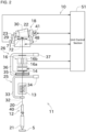
FIG. 2 is a front view and a block diagram of a winding unit. -
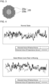
FIG. 3 is a cross-sectional view illustrating a configuration of a yarn. -
FIG. 4 is a graph showing a difference in detection result between a normal state and a state where a core fiber is missing. -
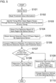
FIG. 5 is a flowchart illustrating a process of determining the presence or absence of a core fiber in a seam region. -
FIG. 6 is a flowchart illustrating a process of determining the presence or absence of a core fiber in a seam region according to a second embodiment. -
FIG. 7 is a flowchart illustrating a flow of an operation of a winding unit according to the second embodiment. -
FIG. 8 is a flowchart illustrating a process of determining the presence or absence of a core fiber in a seam region according to a third embodiment. -
FIG. 9 is a front view of a winding unit according to the third embodiment. -
FIG. 10 is a flowchart illustrating a process of detecting protrusion of a core fiber according to a fourth embodiment. -
FIG. 11 is a front view of a winding unit according to the fourth embodiment. -
FIG. 12 is a front view of a winding unit according to a fifth embodiment. - Next, with reference to the drawings, an embodiment of the present invention will be described. It is noted that "upstream" and "downstream" as used herein mean an upstream and a downstream in a running direction of a yarn during winding the yarn.
- As illustrated in
FIG. 1 , an automatic winder (yarn winding machine) 1 of a first embodiment includes a plurality of windingunits 10 arranged side by side, a doffingapparatus 60, and amachine control apparatus 90. - As illustrated in
FIG. 2 , each windingunit 10 traverses ayarn 20 unwound from ayarn supplying bobbin 21 set on a tray (yarn supplying section) 5 while winding theyarn 20 on a cone-shaped windingtube 22 supported by acradle 23, to form a cone-shapedpackage 30. It is noted that the windingunit 10 may be configured to wind theyarn 20 around the windingtube 22 having a cylindrical shape to form thepackage 30 having a cheese shape. - As illustrated in
FIG. 3 , theyarn 20 wound by the windingunit 10 includes acore fiber 20a and acover fiber 20b. Thecore fiber 20a is an elastic yarn or a synthetic yarn. Examples of thecore fiber 20a includes polyurethane, nylon, or acrylic. Thecore fiber 20a has elasticity. The elasticity means that a high elasticity is provided as compared to thecover fiber 20b or a typical natural fiber yarn. Thecover fiber 20b is wound around an outer periphery of thecore fiber 20a. Thecover fiber 20b may be a natural fiber yarn, an elastic yarn, or a synthetic yarn. - The doffing
apparatus 60 runs to a position of the windingunit 10 where thepackage 30 is fully wound, and removes the fully woundpackage 30 of the windingunit 10 from thecradle 23. The doffingapparatus 60 further supplies the windingtube 22 around which theyarn 20 is not wound yet, to the windingunit 10. - The
machine control apparatus 90 includes amachine input section 91 and amachine display unit 92. In themachine input section 91, an operator inputs a predetermined setting value or selects an appropriate control method, and thus, it is possible to perform setting on each windingunit 10. The operator sets, for example, information about theyarn 20 to be wound (yarn information). The yarn information includes at least one of a material (type), a thickness (count), and the number of twists of each of thecore fiber 20a and thecover fiber 20b. - Next, with reference to
FIG. 2 , a configuration of the windingunit 10 will be specifically described. As illustrated inFIG. 2 , each windingunit 10 includes a winding unitmain body 11 and a unit control section (control section) 51. - The
unit control section 51 includes, for example, an arithmetic apparatus such as a CPU, a RAM, a ROM, an I/O port, and a communication port. The ROM is recorded thereon with a program for controlling each component of the winding unitmain body 11. The I/O port and the communication port are connected with each component provided in the winding unitmain body 11 and themachine control apparatus 90, as a result of which it is possible to perform communication of control information and the like. As a result, theunit control section 51 is capable of controlling an operation of each component included in the winding unitmain body 11. - The winding unit
main body 11 includes, in order from the upstream side, a yarn unwindingauxiliary device 12, atension applying section 13, ayarn splicing section 14, amonitoring section 16, and a windingsection 18. - The yarn unwinding
auxiliary device 12 lowers a regulatingmember 40 covering a core tube of theyarn supplying bobbin 21 in conjunction with unwinding of theyarn 20 from theyarn supplying bobbin 21 to assist with unwinding theyarn 20 from theyarn supplying bobbin 21. The regulatingmember 40 contacts a balloon formed on an upper part of theyarn supplying bobbin 21 due to rotation of theyarn 20 unwound from theyarn supplying bobbin 21 and a centrifugal force, and controls such a balloon to an appropriate size to assist with unwinding theyarn 20. - The
tension applying section 13 applies a predetermined tension to the runningyarn 20. Thetension applying section 13 is of a gate type in which movable comb teeth are arranged relative to fixed comb teeth. The movable comb teeth are capable of rotation by a rotary solenoid. As a result, it is possible to change the tension to be applied by thetension applying section 13 to theyarn 20. It is noted that in addition to the gate type described above, for example, it is possible to adopt a disk type as thetension applying section 13. - The
yarn splicing section 14 splices a lower yarn on ayarn supplying bobbin 21 side (yarn on a yarn supplying section side) and an upper yarn on apackage 30 side (yarn on a package side), when themonitoring section 16 cuts a yarn after detecting a yarn defect or when a yarn unwound from theyarn supplying bobbin 21 is cut, for example. Specifically, when theyarn splicing section 14 splices a lower yarn and an upper yarn which have been first untwisted, overlapped, and twisted again. In the following description, a location where a yarn is spliced will be referred to as a seam region. It is possible to adopt a mechanical configuration or a configuration using a fluid such as compressed air for theyarn splicing section 14. - The
monitoring section 16 monitors a state of theyarn 20. In detecting an abnormality in theyarn 20, themonitoring section 16 cuts theyarn 20 using an unillustrated cutter. Themonitoring section 16 includes anoptical sensor 16a and acapacitance sensor 16b. Theoptical sensor 16a and thecapacitance sensor 16b are fixed to one case. However, theoptical sensor 16a and thecapacitance sensor 16b may be fixed to separate cases and placed apart from each other. Themonitoring section 16 may include only one of theoptical sensor 16a and thecapacitance sensor 16b. - The
optical sensor 16a is a transmission type sensor and includes a light source and a light receiving section. The light source and the light receiving section are arranged on one side and the other side across a yarn path. The light source radiates light toward the yarn path (towards the light receiving section). The light receiving section receives the light radiated by the light source and transmitted through theyarn 20. As a result, as theyarn 20 becomes thicker, an amount of light received by the light receiving section decreases. As described above, theoptical sensor 16a is capable of detecting a thickness of theyarn 20. A detection result of theoptical sensor 16a is output to theunit control section 51. The detection result as used herein includes not only a value directly detected by a sensor (detected value), but also a value obtained by converting the detected value, and a value calculated based on the detected value. - The
capacitance sensor 16b detects a change in capacitance caused by the presence or absence of theyarn 20. A mass of the yarn 20 (in other words, an amount of fibers) is calculated from the detected change in capacitance. A thickness of theyarn 20 is determined based on the mass of theyarn 20. However, if thecore fiber 20a is missing, the mass of theyarn 20 is lower than the thickness of theyarn 20 in appearance. A detection result of thecapacitance sensor 16b is output to theunit control section 51. - On the downstream and upstream sides of the
yarn splicing section 14, a loweryarn catching member 25 configured to catch an yarn end of the lower yarn on theyarn supplying bobbin 21 side and guide the caught yarn end to theyarn splicing section 14, and an upperyarn catching member 26 configured to catch an yarn end of the upper yarn on thepackage 30 side and guide the caught yarn end to theyarn splicing section 14 are arranged, respectively. The loweryarn catching member 25 includes a loweryarn pipe arm 33 and a loweryarn suction port 32 formed at a distal end of the loweryarn pipe arm 33. The upperyarn catching member 26 includes an upperyarn pipe arm 36 and an upperyarn suction port 35 formed at a distal end of the upperyarn pipe arm 36. - The lower
yarn pipe arm 33 and the upperyarn pipe arm 36 are rotatable aboutshafts yarn pipe arm 33 and the upperyarn pipe arm 36 are connected with appropriate suction sources (not illustrated), respectively. As a result, suction flows are generated in the loweryarn suction port 32 and the upperyarn suction port 35, and thus, it is possible to suction and catch the yarn ends of the upper yarn and the lower yarn, respectively, by the loweryarn pipe arm 33 and the upperyarn pipe arm 36. - The winding
section 18 includes thecradle 23 configured to detachably support the windingtube 22, acontact roller 29 capable of rotation in contact with an outer peripheral surface of the windingtube 22 or an outer peripheral surface of thepackage 30, atraverse arm 71, and atraverse drive motor 72. - The
cradle 23 is rotatable about arotation shaft 48. When a yarn layer widens along with theyarn 20 wound around the windingtube 22, thecradle 23 rotates accordingly. As a result, it is possible to eliminate an influence of a shape change due to the widening of the yarn layer. - The
cradle 23 is attached with apackage drive motor 41. When the windingtube 22 is rotationally driven by thepackage drive motor 41, theyarn 20 is wound around the windingtube 22. When the windingtube 22 is supported on thecradle 23, a motor shaft of thepackage drive motor 41 is connected so as not to rotate relative to the winding tube 22 (so-called direct drive system). An operation of thepackage drive motor 41 is controlled by theunit control section 51 via a motor driver (not illustrated). It is noted that instead of the direct drive method, thepackage 30 may be rotationally driven by rotating a contact roller brought into contact with thepackage 30. - The
traverse arm 71 engages with theyarn 20 to traverse theyarn 20. Thetraverse arm 71 is driven by thetraverse drive motor 72. Specifically, thetraverse arm 71 is provided to continuously reciprocate in a package width direction (axial direction of the windingtube 22 and the package 30) in conjunction with the rotation of a rotor of thetraverse drive motor 72. An operation of thetraverse drive motor 72 is controlled by theunit control section 51 via an unillustrated motor driver. For example, a distal end of thetraverse arm 71 is formed with a hook-shaped yarn guide section, for example. When thetraverse arm 71 is reciprocated and turned in a state where theyarn 20 is held by the yarn guide section, it is possible to traverse theyarn 20. It is noted that, instead of thetraverse arm 71, a traverse groove formed on the contact roller may be used to traverse theyarn 20. - When the
package 30 is rotationally driven while the yarn is traversed by thetraverse arm 71, theyarn 20 is wound around the windingtube 22 to realize formation of thepackage 30. - Next, with reference to
FIG. 4 andFIG. 5 , a process for determining the presence or absence of thecore fiber 20a in the seam region will be described. - When the
yarn splicing section 14 performs yarn splicing, thecore fiber 20a may miss in the seam region due to an elasticity of thecore fiber 20a. In a conventional configuration, it is difficult to detect whether thecore fiber 20a is missing. For example, theoptical sensor 16a detects an external appearance of theyarn 20, and thus, it is not possible to detect an internal state of theyarn 20. Thecapacitance sensor 16b detects the mass of theyarn 20, and thus, a value in which the internal state of theyarn 20 is taken into account is detected, but it is not possible to determine whether the mass is small due to the missing of thecore fiber 20a, or whether the mass is small due to theyarn 20 itself being thin. - In this regard, in the present embodiment, when the both
optical sensor 16a andcapacitance sensor 16b are provided, it is possible to detect the missing of thecore fiber 20a. Specifically, a difference between the detection result of theoptical sensor 16a and the detection result of thecapacitance sensor 16b is used. The detection result of theoptical sensor 16a is a thickness of theyarn 20, and the detection result of thecapacitance sensor 16b is a mass of theyarn 20. Therefore, in order to calculate the difference between the detection result of theoptical sensor 16a and the detection result of thecapacitance sensor 16b, it is necessary to use a comparable unit for the two detection results. Here, based on the yarn information input by the operator to themachine control apparatus 90, it is possible to know a density of theyarn 20. Based on the thickness of theyarn 20 and the density of theyarn 20, it is possible to calculate the mass of theyarn 20. Therefore, it is possible to convert the thickness of theyarn 20 detected by theoptical sensor 16a into the mass of theyarn 20. As a result, when the mass of theyarn 20 is used, it is possible to calculate the difference between the detection result of theoptical sensor 16a and the detection result of thecapacitance sensor 16b. Further, based on the mass of theyarn 20 and the density of theyarn 20, it is possible to calculate the thickness of theyarn 20. Therefore, it is possible to convert the mass of theyarn 20 detected by thecapacitance sensor 16b into the thickness theyarn 20. As a result, when the thickness of theyarn 20 is used, it is also possible to calculate the difference between the detection result of theoptical sensor 16a and the detection result of thecapacitance sensor 16b. - A graph in the upper part of
FIG. 4 shows the detection result of theoptical sensor 16a and the detection result of thecapacitance sensor 16b for theyarn 20 in a normal state (that is, theyarn 20 including thecore fiber 20a and thecover fiber 20b). A graph in the lower part ofFIG. 4 shows the detection result of theoptical sensor 16a and the detection result of thecapacitance sensor 16b for theyarn 20 with thecore fiber 20a missing (that is, thecover fiber 20b). A difference in detection result for theyarn 20 with thecore fiber 20a missing is larger than a difference in detection result for theyarn 20 in the normal state. This is because, in the normal state and in the state where thecore fiber 20a is missing, the detection result of theoptical sensor 16a does not change significantly, but the detection result of thecapacitance sensor 16b changes greatly. Taking advantage of such a feature, in the present embodiment, the difference between the detection result of theoptical sensor 16a and the detection result of thecapacitance sensor 16b for the seam region is used to determine the presence or absence of the missing of thecore fiber 20a in the seam region. - With reference to a flowchart in
FIG. 5 , such a process will be described in detail below. The flowchart illustrated inFIG. 5 is executed by theunit control section 51. After starting a yarn splicing (S101), theunit control section 51 reads threshold value information (S102). The threshold value information is information in which yarn information and a threshold value are associated with each other, and is previously stored in theunit control section 51. Theunit control section 51 selects and reads a corresponding threshold value, based on the yarn information input by the operator to themachine control apparatus 90. It is noted that a timing at which the threshold value information is read is just one example, and the threshold information may be read before the start of the yarn splicing. Instead of the process of reading the threshold value every time the yarn is spliced, theunit control section 51 may continue to store the same threshold value until the yarn information is changed, for example. - The threshold value is used to determine whether the
core fiber 20a is missing in the seam region. Therefore, the threshold value indicated by the threshold value information is larger than a value (average value of the differences, for example) based on the difference between the detection result of theoptical sensor 16a and the detection result of thecapacitance sensor 16b in the normal state. The threshold value indicated by the threshold value information is smaller than a value (average value of the differences, for example) based on the difference between the detection result of theoptical sensor 16a and the detection result of thecapacitance sensor 16b in a state where thecore fiber 20a in the seam region is missing. - Next, the
unit control section 51 specifies the timing at which the seam region passes through themonitoring section 16, and reduces a winding speed at such a timing (S103). Here, theunit control section 51 performs control regarding the yarn splicing, and thus, the timing at which the yarn splicing is completed is known. Theunit control section 51 controls the windingsection 18, and thus, the winding speed of theyarn 20 is known. A distance from theyarn splicing section 14 to themonitoring section 16 is known. Thus, theunit control section 51 is capable of specifying the timing at which the seam region passes through themonitoring section 16. Alternatively, theunit control section 51 may estimate that the seam region passes through themonitoring section 16 at a timing when a predetermined period of time elapses since the completion of the yarn splicing. The predetermined time may be evaluated in advance experimentally or by simulation and stored in theunit control section 51. - The winding speed is decreased by the
unit control section 51 controlling the windingsection 18. When the winding speed is decreased, the winding speed at the timing when the seam region passes through themonitoring section 16 is less than the winding speed during a steady state. The winding speed during a steady state is a winding speed set as a winding condition. In other words, such a winding speed is a winding speed while theyarn 20 is wound to form the package 30 (excluding when the yarn is spliced). It is noted that as a result of the decrease in winding speed, the winding speed obtained when the seam region is located at themonitoring section 16 may be 0. Instead of the process of decreasing the winding speed, the winding may be restarted at a winding speed less than the winding speed during a steady state after the yarn splicing, and in such a state, the seam region may pass through themonitoring section 16. - Next, the
unit control section 51 obtains the detection result of the seam region (hereinafter referred to as a first detection result) by theoptical sensor 16a at the timing when the seam region passes through the monitoring section 16 (S104). Theunit control section 51 obtains the detection result (hereinafter referred to as a second detection result) of the seam region by thecapacitance sensor 16b at the timing when the seam region passes through the monitoring section 16 (S105). The winding speed is decreased at the timing when the seam region passes through themonitoring section 16, and thus, theoptical sensor 16a and thecapacitance sensor 16b are capable of accurately detecting the state of theyarn 20. - Next, the
unit control section 51 compares the difference between the first detection result and the second detection result with a threshold value (S106). Such a process is performed by making the units of the first detection result and the second detection result comparable, as described above. A method for calculating the difference includes, for example, calculating a difference between an average value of the detection results of theoptical sensor 16a and an average value of the detection results of thecapacitance sensor 16b. Alternatively, another method may include calculating the difference between the first detection result and the second detection result. - The
unit control section 51 determines whether the difference is less than or equal to the threshold value (S107). As described above, when thecore fiber 20a is missing, the second detection result is larger than the first detection result. That is, when the difference is less than or equal to the threshold value, theunit control section 51 determines that thecore fiber 20a is present in the seam region (S108). On the other hand, if the difference exceeds the threshold value, theunit control section 51 determines that there is nocore fiber 20a in the seam region, and notifies as such (S109). In a notification method, for example, themachine control apparatus 90 or theunit control section 51 may light or blink an alarm lamp, or may generate an alarm sound. Alternatively, theunit control section 51 may transmit a message to an operator terminal or an administrator terminal. - Thus, when the detection results of the
optical sensor 16a and thecapacitance sensor 16b are used, it is possible to accurately detect whether or not thecore fiber 20a is missing in the seam region of theyarn 20. - If there is no
core fiber 20a in the seam region, there may be room for improvement in an operation setting of theyarn splicing section 14. For example, if an overlapping length of the lower yarn on ayarn supplying bobbin 21 side and an upper yarn on thepackage 30 side is short, thecore fiber 20a may be missing. Therefore, when an amount of operation of a yarn pulling lever that pulls a yarn is increased, thecore fiber 20a may be less likely to be missing. Alternatively, when a time for untwisting or twisting is lengthened, thecore fiber 20a may be less likely to be missing. In the present embodiment, in determining that there is nocore fiber 20a in the seam region, theunit control section 51 changes the operation setting of the yarn splicing section 14 (S110). As a result, during a subsequent yarn splicing, it is possible to reduce a probability that thecore fiber 20a is missing. It is noted that the process in step S110 is not essential and may be omitted or executed once every three times, for example. - In the present embodiment, when the
core fiber 20a is missing, a notification to such an effect is applied and the process is continued. Instead of such a process, the yarn splicing may be attempted again. The attempting again of the yarn spicing means that themonitoring section 16 cuts theyarn 20, and theyarn splicing section 14 performs the yarn splicing between the lower yarn on theyarn supplying bobbin 21 side and the upper yarn on thepackage 30 side again. In the attempting again of the yarn splicing, the change in the operation setting of theyarn splicing section 14 set in step S 110 is applied, and thus, thecore fiber 20a is less likely to be missing. - Next, with reference to
FIG. 6 andFIG. 7 , a second embodiment will be described. It is noted that in the following description, a configuration other than the explicitly stated parts has the same configuration as theautomatic winder 1 of the first embodiment. The same steps as those in the first embodiment are allotted the same step numbers, and the description thereof will be omitted. - In the second embodiment, the presence or absence of the
core fiber 20a is determined by changing a tension of theyarn 20. As described above, theunit control section 51 controls thetension applying section 13 to change an amount of operation of the movable comb teeth to thereby change the tension of theyarn 20. Hereinafter, a state where thetension applying section 13 applies a first tension to theyarn 20 is called a first tension and a state where thetension applying section 13 applies a second tension (tension smaller than the first tension) to theyarn 20 is called a second state. When thetension applying section 13 is switched from the first state to the second state, theyarn 20 is loosened, and thus, theyarn 20 is likely to shrink. - A method of reducing the tension of the
yarn 20 to shrinking theyarn 20 is not limited to using thetension applying section 13. For example, theunit control section 51 is capable of shrinking theyarn 20 by controlling the windingsection 18 to decrease the winding speed. In such a case, the winding section 18 (more specifically, the package drive motor 41) corresponds to the "tension applying section". For example, theunit control section 51 is capable of increasing the tension by the yarn splicing section 14 (more specifically, the yarn pulling lever that pulls the yarn 20) coming into contact with theyarn 20, after the yarn splicing by theyarn splicing section 14, and capable of shrinking theyarn 20 by reducing the tension by releasing the contact of theyarn 20 by theyarn splicing section 14. In such a case, the yarn splicing section 14 (more specifically, the yarn pulling lever) corresponds to the "tension applying section". For example, theunit control section 51 is capable of increasing the tension applied to theyarn 20 by injecting a cleaning compressed air of themonitoring section 16 to theyarn 20, and capable of shrinking theyarn 20 by reducing the tension by releasing the injection of the compressed air. In such a case, the monitoring section 16 (more specifically, a compressed air injection section) corresponds to the "tension applying section". When the compressed air is injected to theyarn 20, it is possible to influence a tension change locally applied to theyarn 20 to other parts of theyarn 20. - When the
core fiber 20a is included in the seam region, the seam region and other parts shrink to the same extent. When there is nocore fiber 20a in the seam region, expansion and contraction is less likely to occur due to the absence of thecore fiber 20a, and thus, an amount of shrinkage in the seam region is smaller than an amount of shrinkage in other parts. That is, the amount of shrinkage in the seam region differs depending on the tension applied to theyarn 20, and thus, the detection results of the seam regions with different tension application conditions are compared, so that it is possible to determine the presence or absence of thecore fiber 20a in the seam region. When the amounts of shrinkage between the seam region and the other parts are compared, it is also possible to determine the presence or absence of thecore fiber 20a in the seam region. - In the second embodiment, after the yarn splicing (S101, upper left in
FIG. 7 ), theunit control section 51 sets thetension applying section 13 to the second state (S201). Theunit control section 51 obtains the detection results of theoptical sensor 16a and thecapacitance sensor 16b at the timing when the seam region (reference numeral 20c inFIG. 7 ) passes through the monitoring section 16 (S202, upper right inFIG. 7 ). - Next, after the seam region passes through the
monitoring section 16, theunit control section 51 returns theyarn 20 to the upstream side of the monitoring section 16 (S203, lower left inFIG. 7 ). Specifically, theunit control section 51 suctions theyarn 20 by using anauxiliary nozzle 81 while controlling the windingsection 18 to reverse thepackage 30. As a result, the seam region is sent back to the upstream side. It is noted that instead of theauxiliary nozzle 81, the loweryarn catching member 25 may be used to suction theyarn 20. Alternatively, the yarn pulling lever of theyarn splicing section 14 may be used to move theyarn 20 to the upstream side. - Next, the
unit control section 51 sets thetension applying section 13 to the first state (S204). As a result, the tension of theyarn 20 is increased. Theunit control section 51 obtains the detection results of theoptical sensor 16a and thecapacitance sensor 16b at the timing when the seam region passes through themonitoring section 16 again (S205, lower right inFIG. 7 ). - Next, the
unit control section 51 compares the first and second detection results (S206). Specifically, theunit control section 51 compares a degree of shrinkage in the seam region between the first and second times. At the first time, the tension of theyarn 20 is small, and thus, theyarn 20 is likely to shrink. However, if there is nocore fiber 20a in the seam region, the seam region shrinks only little. On the other hand, at the second time, the tension of theyarn 20 is large, and thus, theyarn 20 does not shrink, and theyarn 20 is likely to be straight. That is, when thecore fiber 20a is present in the seam region, a difference in degree of shrinkage between the first and second times is large. On the other hand, if there is nocore fiber 20a in the seam region, the difference in degree of shrinkage between the first and second times is small. Theunit control section 51 compares the first-time degree of shrinkage in the seam region with the second-time degree of shrinkage in the seam region. When the degree of shrinkage is large, an amount of fibers in theyarn 20 per unit length increases, and thus, the thickness of theyarn 20 detected by theoptical sensor 16a and the thickness of theyarn 20 detected by thecapacitance sensor 16b increase, and therefore, it is possible to detect the degree of shrinkage by using these sensors. Theunit control section 51 compares the threshold value in much the same way as in the first embodiment, based on a comparison value obtained by such a comparison. Subsequent processes are the same as those in the first embodiment. - As described above, based on the degree of shrinkage obtained when the tensions are differed, it is possible to determine the presence or absence of the
core fiber 20a in the seam region. In the second embodiment, the first-time detection result is obtained with thetension applying section 13 being in the second state, and next, the second-time detection result is acquired with thetension applying section 13 being in the first state. In other words, a state where the tension is small is changed to a state where the tension is large. Therefore, a level of tension applied to theyarn 20 is not likely to spread in the running direction of theyarn 20, and thus, it is possible to obtain a more appropriate detection result. - It is noted that in the second embodiment, the seam region is measured twice. Alternatively, the seam region may be measured only once with a small change in tension. In such a case, the
unit control section 51 compares the degree of shrinkage in the seam region with the degree of shrinkage in regions other than in the seam region. When thecore fiber 20a is present in the seam region, the degree of shrinkage is the same in the seam region and other regions. When there is nocore fiber 20a in the seam region, the degree of shrinkage in the seam region is smaller than the degree of shrinkage in the other regions. Thus, even if the seam region is measured only once, it is possible to determine the presence or absence of thecore fiber 20a in the seam region, based on the degree of shrinkage. - It is noted that instead of the processes of the second embodiment, it may be possible that firstly, the
tension applying section 13 is set in the first state and the first detection result by themonitoring section 16 is obtained, and next, thetension applying section 13 is set to the second state and the second detection result by themonitoring section 16 is obtained. - The processes of the first embodiment and the second embodiment may be combined. That is, if it is determined that in the process of the first embodiment, the
core fiber 20a is present in the seam region and it is further determined that in the process of the second embodiment, thecore fiber 20a is present in the seam region, it may be determined that thecore fiber 20a is present in the seam region. - Next, with reference to
FIG. 8 andFIG. 9 , a third embodiment will be described. - In the second embodiment, the
yarn 20 is returned and passed through thesame monitoring section 16 twice, whereas in the third embodiment, theyarn 20 is not returned but passed through two monitoring sections in order. Therefore, as illustrated inFIG. 9 , the windingunit 10 of the third embodiment further includes asecond monitoring section 17. Thesecond monitoring section 17 is arranged downstream of themonitoring section 16. Similarly to themonitoring section 16, thesecond monitoring section 17 includes anoptical sensor 17a and acapacitance sensor 17b. - The
unit control section 51 sets thetension applying section 13 to the second state (S401), passes the seam region through themonitoring section 16, and obtains the detection results in the seam region by theoptical sensor 16a and thecapacitance sensor 16b (S402). Next, after the seam region passes through themonitoring section 16, theunit control section 51 sets thetension applying section 13 to the first state (S403), passes the seam region through thesecond monitoring section 17, and obtains the detection results of the seam region by theoptical sensor 17a and thecapacitance sensor 17b (S404). - As a result, in the third embodiment, it is possible to obtain a similar detection result to that of the second embodiment without a need of returning the
yarn 20. Subsequent processes are the same as those in the second embodiment. - In the third embodiment, the
monitoring section 16 and thesecond monitoring section 17 have the same configuration. Instead, themonitoring section 16, and an expansion contraction detection section which is a simpler sensor than themonitoring section 16, may be provided. The simpler sensor is, for example, an optical sensor or a capacitance sensor having lower accuracy than themonitoring section 16. Alternatively, the simpler sensor may be an image capturing apparatus. In such a case, the expansion contraction detection section is arranged upstream of themonitoring section 16. The expansion contraction detection section measures the seam region when thetension applying section 13 is in the second state, and thereafter, themonitoring section 16 measures the seam region when thetension applying section 13 is in the first state. Although it is preferable that the expansion contraction detection section measures the seam region, the expansion contraction detection section may measure regions other than the seam region. - Next, with reference to
FIG. 10 andFIG. 11 , a fourth embodiment will be described. - The
automatic winder 1 of the fourth embodiment further includes a function of detecting protrusion of thecore fiber 20a in the seam region. Specifically, as illustrated inFIG. 11 , the windingunit 10 includes animaging device 19. Theimaging device 19 is arranged downstream of theyarn splicing section 14. In the present embodiment, in the vicinity of theyarn splicing section 14, in particular, in the running direction of the yarn, theimaging device 19 is arranged between theyarn splicing section 14 and themonitoring section 16. When theimaging device 19 is arranged at such as position, it is possible to image theyarn 20 after the yarn splicing is performed and in a state where theyarn 20 stops running. It is noted that theimaging device 19 may be arranged downstream of themonitoring section 16. Theimaging device 19 images the yarn and outputs an imaging result to theunit control section 51. - The
unit control section 51 obtains the result of (an image obtained by imaging) the seam region imaged by the imaging device 19 (S501). Theunit control section 51 determines the presence or absence of the protrusion of thecore fiber 20a in the seam region, based on the imaging result of the seam region (S502). Theunit control section 51 analyzes the imaging result of the seam region, and if it is possible to identify thecore fiber 20a protruded from thecover fiber 20b, it determines that thecore fiber 20a is protruded. In determining that there is protrusion of thecore fiber 20a in the seam region (S503), theunit control section 51 notifies that thecore fiber 20a is protruded (S504). The notification method is the same as in the first embodiment. - Next, with reference to
FIG. 12 , a fifth embodiment will be described. - The
automatic winder 1 of the fifth embodiment differs from theautomatic winder 1 of the fourth embodiment in the method of detecting the protrusion of thecore fiber 20a in the seam region. Specifically, in addition to thecapacitance sensor 16b, themonitoring section 16 of theautomatic winder 1 of the fifth embodiment further includes two types of optical sensors, in particular, atransmission type sensor 16c and areflection type sensor 16d. Thetransmission type sensor 16c has the same configuration as theoptical sensor 16a of the first embodiment. Thereflection type sensor 16d includes a light source and a light receiving section. The light source irradiates theyarn 20 with light. The light receiving section receives light irradiated by the light source and then reflected by theyarn 20. Therefore, as theyarn 20 is thicker, an amount of light detected by the light receiving section increases. The amount of light detected by the light receiving section changes depending on a state of thecover fiber 20b in the yarn 20 (that is, depending on the presence or absence of the protrusion of thecore fiber 20a). It is noted that the light source may be common to thetransmission type sensor 16c and thereflection type sensor 16d, or separate light sources may be provided. - In the fifth embodiment, the
unit control section 51 mainly uses thereflection type sensor 16d to determine the presence or absence of the protrusion of thecore fiber 20a in the seam region. That is, if thecore fiber 20a protrudes in the seam region, light is reflected at such a protruded portion. Therefore, theunit control section 51 is capable of determining the presence or absence of the protrusion of thecore fiber 20a in the seam region, based on the detection result of thereflection type sensor 16d. - It is noted that in order to accurately determine the presence or absence of the protrusion of the
core fiber 20a in the seam region, the detection results of thecapacitance sensor 16b and thetransmission type sensor 16c may be further used. That is, when the amount of light detected by thereflection type sensor 16d is corrected with the amount of light detected by thetransmission type sensor 16c, it is possible to accurately determine the presence or absence of the protrusion of thecore fiber 20a. It is possible to use the detection result of thecapacitance sensor 16b to accurately identify the position of the seam region. That is, theyarns 20 are twisted in an overlapping manner in the seam region, and thus, the mass (fiber amount) in the seam region is larger than in other locations. Thecapacitance sensor 16b detects the mass of theyarn 20, and thus, it is possible to identify a location where the detection result is large as the seam region. With thereflection type sensor 16d only, the light may be reflected by a foreign matter attached to theyarn 20. In such a regard, in addition to the detection result of thereflection type sensor 16d, when the detection result of thetransmission type sensor 16c is used, it is possible to reduce the influence of the foreign matter and determine the presence or absence of the protrusion of thecore fiber 20a in the seam region. - Although the
monitoring section 16 of the above embodiment includes both theoptical sensor 16a and thecapacitance sensor 16b, themonitoring section 16 may include only one of theoptical sensor 16a and thecapacitance sensor 16b. Even with such a configuration, it is possible to detect the missing of thecore fiber 20a in the seam region by performing the following process. That is, under an influence of the presence or absence of thecore fiber 20a, the detection result of theoptical sensor 16a in the normal state is slightly larger than the detection result of theoptical sensor 16a in the state where thecore fiber 20a is missing. As described above, the detection results of thecapacitance sensor 16b are significantly different between the normal state and the state where thecore fiber 20a is missing. Therefore, if a threshold value having a size between such detection results is set and if the detection result is smaller than the threshold value, it is possible to determine that thecore fiber 20a is missing. - As described above, the
automatic winder 1 of the above embodiment includes atray 5, themonitoring section 16, theyarn splicing section 14, the windingsection 18, and theunit control section 51. Thetray 5 supplies theyarn 20 including thecore fiber 20a formed of an elastic yarn and thecover fiber 20b wound around thecore fiber 20a. Themonitoring section 16 monitors a state of theyarn 20. Theyarn splicing section 14 is arranged upstream of themonitoring section 16 in the running direction of theyarn 20, and performs the yarn splicing between theyarn 20 on atray 5 side and theyarn 20 on apackage 30 side. The windingsection 18 winds theyarn 20 to form thepackage 30. Themonitoring section 16 includes at least one of theoptical sensor 16a and thecapacitance sensor 16b. Theoptical sensor 16a detects the thickness of theyarn 20. Thecapacitance sensor 16b detects the mass of theyarn 20. Theunit control section 51 determines the presence or absence of thecore fiber 20a in the seam region, based on the detection result of themonitoring section 16 for the seam region where the yarn is spliced by theyarn splicing section 14. - As a result, based on the detection result of the
monitoring section 16, it is possible to detect the presence or absence of thecore fiber 20a in the seam region. - In the
automatic winder 1 of the above embodiment, theunit control section 51 controls the windingsection 18 so that the winding speed of theyarn 20 when the seam region passes through themonitoring section 16 is less than the winding speed of theyarn 20 during a steady state. - As a result, the detection accuracy of the
monitoring section 16 is increased, and thus, it is possible to further accurately detect the presence or absence of thecore fiber 20a. - In the
automatic winder 1 of the above embodiment, themonitoring section 16 includes theoptical sensor 16a and thecapacitance sensor 16b. Theunit control section 51 determines the presence or absence of thecore fiber 20a in the seam region, based on a difference between the detection result of theoptical sensor 16a and the detection result of thecapacitance sensor 16b, and a threshold value previously determined, according to the yarn information of theyarn 20 that is being wound, for the difference. - When the threshold value is determined, it is possible to determine the presence or absence of the
core fiber 20a with a simpler method. When the threshold value according to the yarn information is set, it is possible to accurately detect the presence or absence of thecore fiber 20a. - In the
automatic winder 1 of the embodiment described above, themonitoring section 16 includes theoptical sensor 16a including thereflection type sensor 16d configured to detect reflected light reflected by theyarn 20. Theunit control section 51 determines the presence or absence of the protrusion of thecore fiber 20a from thecover fiber 20b, based on the detection result of thereflection type sensor 16d. - As a result, it is possible to further detect the protrusion of the
core fiber 20a without adding a sensor. - In the
automatic winder 1 of the above embodiment, themonitoring section 16 includes theoptical sensor 16a and thecapacitance sensor 16b. Theoptical sensor 16a includes thetransmission type sensor 16c configured to detect the transmitted light transmitting through the region where theyarn 20 is positioned, and thereflection type sensor 16d configured to detect the reflected light reflected by theyarn 20. Theunit control section 51 determines the presence or absence of the protrusion of thecore fiber 20a from thecover fiber 20b, based on the detection result of thetransmission type sensor 16c, the detection result of thereflection type sensor 16d, and the detection result of thecapacitance sensor 16b. - As a result, when the two types of sensors, that is, the optical sensor and the
capacitance sensor 16b, are used, it is possible to accurately detect the protrusion of thecore fiber 20a. - The
automatic winder 1 of the above embodiment includes thetension applying section 13 capable of switching between the first state in which the tension is applied to theyarn 20 and the second state in which the tension applied to theyarn 20 is smaller than in the first state. Theunit control section 51 controls so that thetension applying section 13 is set to the second state and the seam region passes through themonitoring section 16. - If the
core fiber 20a in the seam region is missing, shrinkage in the seam region is unlikely to occur even if the tension is reduced. Therefore, when the information on the seam region in a state where the tension is small is detected, it is possible to accurately detect the presence or absence of thecore fiber 20a in the seam region. - In the
automatic winder 1 of the above embodiment, theunit control section 51 controls so that after thetension applying section 13 is set to the second state and the seam region passes through themonitoring section 16, the position of the seam region is returned to the upstream of themonitoring section 16, and thetension applying section 13 is set to the first state and the seam region passes through themonitoring section 16. - As a result, it is possible to change the tension and detect the information about the seam region without providing the two
monitoring sections 16. - The
automatic winder 1 of the above embodiment includes thesecond monitoring section 17 arranged downstream of themonitoring section 16 in the running direction of theyarn 20 and configured to monitor the state of theyarn 20. Theunit control section 51 controls so that thetension applying section 13 is set to the second state and the seam region thereafter passes through themonitoring section 16, and after thetension applying section 13 is set to the first state and the seam region thereafter passes through thesecond monitoring section 17. - As a result, it is possible to detect the information about the seam region by changing the tension without moving the
yarn 20 in an opposite direction. - The
automatic winder 1 of the above embodiment includes the expansion contraction detection section arranged upstream of themonitoring section 16 in the running direction of theyarn 20 and configured to detect the expansion and contraction of theyarn 20. Theunit control section 51 determines the presence or absence of thecore fiber 20a in the seam region, based on the detection result of themonitoring section 16 for the seam region and the detection result of the expansion contraction detection section for theyarn 20. - As a result, it is possible to utilize a low-cost sensor as long as it is possible to detect the expansion and contraction of the
yarn 20. - The
automatic winder 1 of the present embodiment includes thetension applying section 13 capable of switching between the first state in which the tension is applied to theyarn 20 and the second state in which the tension applied to theyarn 20 is smaller than in the first state. Theunit control section 51 determines the presence or absence of thecore fiber 20a in the seam region, based on the detection result of the expansion contraction detection section when thetension applying section 13 is in the first state and the detection result of themonitoring section 16 when thetension applying section 13 is in the second state. - When the
tension applying section 13 is provided, it is possible to intentionally generate the expansion and contraction of theyarn 20, and thus, it is possible to accurately detect the expansion and contraction of the seam region. - In the
automatic winder 1 of the embodiment described above, theunit control section 51 changes the operation setting of theyarn splicing section 14 at the time of yarn splicing, based on the detection result of themonitoring section 16. - As a result, it is possible to change the operation setting of the yarn splicing so that an abnormality of the
yarn 20 is less likely to occur. - The
automatic winder 1 of the above embodiment includes theimaging device 19 configured to image the seam region. Theunit control section 51 determines the presence or absence of the protrusion of thecore fiber 20a from thecover fiber 20b, based on the imaging result of theimaging device 19. - As a result, it is possible to detect the protrusion of the
core fiber 20a. - Although the preferred embodiments of the present invention have been described above, the above configuration may be modified as follows, for example.
- The
optical sensor 16a of the first embodiment, which is a transmission type sensor, may be replaced with a reflection type sensor. Theoptical sensor 16a may be configured to include at least one light emitting element and two light receiving elements in which one light receiving element detects reflected light and the other light receiving element detects transmitted light. - The flowchart illustrated in the above embodiment is an example, and some processes may be omitted, the contents of such processes may be changed, or a new process may be added.
- Although the embodiment described above provides an example in which the present invention is applied to the automatic winder, the present invention may also be applied to other yarn winding machines such as a spinning machine instead of the automatic winder.
Claims (12)
- A yarn winding machine (1), comprising:a yarn supplying section (5) configured to supply a yarn (20) including a core fiber (20a) formed of an elastic yarn and a cover fiber (20b) wound around the core fiber (20a);a monitoring section (16) configured to monitor a state of the yarn (20);a yarn splicing section (14) arranged upstream of the monitoring section (16) in a running direction of the yarn (20), the yarn splicing section (14) configured to splice the yarn (20) on a yarn supplying section (5) side and the yarn (20) on a package side;a winding section (18) configured to wind the yarn (20) to form a package; anda control section (51), whereinthe monitoring section (16) includes at least one of an optical sensor (16a) configured to detect a thickness of the yarn (20) and a capacitance sensor (16b) configured to detect a mass of the yarn (20), andthe control section (51) is configured to determine, based on a detection result of the monitoring section (16) for a seam region where the yarn (20) is spliced by the yarn splicing section (14), presence or absence of the core fiber (20a) in the seam region.
- The yarn winding machine (1) according to claim 1, wherein
the control section (51) is configured to control the winding section (18) so that a winding speed of the yarn (20) obtained when the seam region passes through the monitoring section (16) is less than a winding speed of the yarn (20) during a steady state. - The yarn winding machine (1) according to claim 1 or 2, whereinthe monitoring section (16) includes the optical sensor (16a) and the capacitance sensor (16b), andthe control section (51) is configured to determine presence or absence of the core fiber (20a) in the seam region, based on a difference between a detection result of the optical sensor (16a) and a detection result of the capacitance sensor (16b) and based on a threshold value previously defined according to yarn information of the yarn (20) that is being wound for the difference.
- The yarn winding machine (1) according to any one of claims 1 to 3, whereinthe monitoring section (16) includes the optical sensor (16a) including a reflection type sensor (16d) configured to detect reflected light reflected by the yarn (20), andthe control section (51) is configured to determine presence or absence of protrusion of the core fiber (20a) from the cover fiber (20b), based on a detection result of the reflection type sensor (16d).
- The yarn winding machine (1) according to any one of claims 1 to 3,
whereinthe monitoring section (16) includes the optical sensor (16a) and the capacitance sensor (16b),the optical sensor (16a) includes a transmission type sensor (16c) configured to detect transmitted light transmitting a region where the yarn (20) is located, and a reflection type sensor (16d) configured to detect reflected light reflected by the yarn (20), andthe control section (51) is configured to determine presence or absence of a protrusion of the core fiber (20a) from the cover fiber (20b), based on a detection result of the transmission type sensor (16c), a detection result of the reflection type sensor (16d), and a detection result of the capacitance sensor (16b). - The yarn winding machine (1) according to any one of claims 1 to 5, comprising:a tension applying section (13) capable of switching between a first state in which a tension is applied to the yarn (20) and a second state in which a tension applied to the yarn (20) is smaller than in the first state, whereinthe control section (51) is configured to control so that the tension applying section (13) is set to the second state and the seam region thereafter passes through the monitoring section (16).
- The yarn winding machine (1) according to claim 6, wherein
the control section (51) is configured to control so that the tension applying section (13) is set to the second state and the seam region thereafter passes through the monitoring section (16), and thereafter, control so that a position of the seam region is returned to upstream of the monitoring section (16), the tension applying section (13) is set to the first state, and the seam region thereafter passes through the monitoring section (16). - The yarn winding machine (1) according to claim 6, comprising:a second monitoring section (17) arranged downstream of the monitoring section (16) in the running direction of the yarn (20), the second monitoring section (17) configured to monitor a state of the yarn (20), whereinthe control section (51) is configured to control so that the tension applying section (13) is set to the second state and the seam region thereafter passes through the monitoring section (16), and control so that the tension applying section (13) is set to the first state and the seam region thereafter passes through the second monitoring section (17).
- The yarn winding machine (1) according to any one of claims 1 to 5, comprising:an expansion contraction detection section arranged upstream of the monitoring section (16) in the running direction of the yarn (20), the expansion contraction detection section being configured to detect expansion and contraction of the yarn (20), whereinthe control section (51) is configured to determine presence or absence of the core fiber (20a) in the seam region, based on a detection result of the monitoring section (16) for the seam region and a detection result of the expansion contraction detection section for the yarn (20).
- The yarn winding machine (1) according to claim 9, comprising:a tension applying section (13) capable of switching between a first state in which a tension is applied to the yarn (20) and a second state in which a tension applied to the yarn (20) is smaller than in the first state, whereinthe control section (51) is configured to determine presence or absence of the core fiber (20a) in the seam region, based on a detection result of the expansion contraction detection section when the tension applying section (13) is in the first state and a detection result of the monitoring section (16) when the tension applying section (13) is in the second state.
- The yarn winding machine (1) according to any one of claims 1 to 10, wherein
the control section (51) is configured to change an operation setting of the yarn splicing section (14) during a yarn splicing, based on the detection result of the monitoring section (16). - The yarn winding machine (1) according to any one of claims 1 to 11, comprising:an imaging device (19) configured to image the seam region, whereinthe control section (51) is configured to determine presence or absence of a protrusion of the core fiber (20a) from the cover fiber (20b), based on an imaging result of the imaging device (19).
Applications Claiming Priority (1)
| Application Number | Priority Date | Filing Date | Title |
|---|---|---|---|
| JP2023069714A JP2024155219A (en) | 2023-04-21 | 2023-04-21 | Yarn Winding Machine |
Publications (2)
| Publication Number | Publication Date |
|---|---|
| EP4450442A1 true EP4450442A1 (en) | 2024-10-23 |
| EP4450442B1 EP4450442B1 (en) | 2026-03-25 |
Family
ID=90482034
Family Applications (1)
| Application Number | Title | Priority Date | Filing Date |
|---|---|---|---|
| EP24166946.4A Active EP4450442B1 (en) | 2023-04-21 | 2024-03-27 | Yarn winding machine |
Country Status (3)
| Country | Link |
|---|---|
| EP (1) | EP4450442B1 (en) |
| JP (1) | JP2024155219A (en) |
| CN (1) | CN118811612A (en) |
Citations (5)
| Publication number | Priority date | Publication date | Assignee | Title |
|---|---|---|---|---|
| JPH03167330A (en) | 1989-11-25 | 1991-07-19 | Murata Mach Ltd | Method for sensing abnormal yarn in core yarn |
| WO2006030661A1 (en) * | 2004-09-16 | 2006-03-23 | Murata Kikai Kabushiki Kaisha | Core yarn spinning machine, method of determining presence or absence of core of core yarn, and method of servicing in core yarn spinning machine |
| WO2006123454A1 (en) * | 2005-05-16 | 2006-11-23 | Murata Kikai Kabushiki Kaisha | Wadding detecting method and device in core yarn spinning |
| WO2007140639A1 (en) * | 2006-06-07 | 2007-12-13 | Uster Technologies Ag | Method and apparatus for detecting a core in a core yarn |
| DE102020125938A1 (en) * | 2020-10-05 | 2022-04-07 | Saurer Spinning Solutions Gmbh & Co. Kg | Textile machine and method for determining the thread connection quality of a thread connection produced by a thread connection unit of a textile machine |
-
2023
- 2023-04-21 JP JP2023069714A patent/JP2024155219A/en active Pending
-
2024
- 2024-03-27 EP EP24166946.4A patent/EP4450442B1/en active Active
- 2024-04-15 CN CN202410446593.8A patent/CN118811612A/en active Pending
Patent Citations (5)
| Publication number | Priority date | Publication date | Assignee | Title |
|---|---|---|---|---|
| JPH03167330A (en) | 1989-11-25 | 1991-07-19 | Murata Mach Ltd | Method for sensing abnormal yarn in core yarn |
| WO2006030661A1 (en) * | 2004-09-16 | 2006-03-23 | Murata Kikai Kabushiki Kaisha | Core yarn spinning machine, method of determining presence or absence of core of core yarn, and method of servicing in core yarn spinning machine |
| WO2006123454A1 (en) * | 2005-05-16 | 2006-11-23 | Murata Kikai Kabushiki Kaisha | Wadding detecting method and device in core yarn spinning |
| WO2007140639A1 (en) * | 2006-06-07 | 2007-12-13 | Uster Technologies Ag | Method and apparatus for detecting a core in a core yarn |
| DE102020125938A1 (en) * | 2020-10-05 | 2022-04-07 | Saurer Spinning Solutions Gmbh & Co. Kg | Textile machine and method for determining the thread connection quality of a thread connection produced by a thread connection unit of a textile machine |
Also Published As
| Publication number | Publication date |
|---|---|
| CN118811612A (en) | 2024-10-22 |
| JP2024155219A (en) | 2024-10-31 |
| EP4450442B1 (en) | 2026-03-25 |
Similar Documents
| Publication | Publication Date | Title |
|---|---|---|
| CN104925584B (en) | Yarn winding machine and winding method | |
| JP5998709B2 (en) | Yarn monitoring device and yarn winding unit | |
| EP2644553B1 (en) | Yarn defect classifying device and method and yarn winding machine | |
| EP2479130B1 (en) | Yarn winding device | |
| EP2690046B1 (en) | Yarn defect detecting device and winding device | |
| EP2966021A1 (en) | Yarn winding machine and yarn winding method | |
| EP3025995A1 (en) | Yarn winding machine | |
| EP2365115B1 (en) | Yarn winding machine with yarn slack eliminating roller | |
| US6637695B2 (en) | Method of winding a traveling yarn at a work station of a spinning bobbin winding machine or of a bobbin winding machine | |
| EP2169097A1 (en) | Foreign substance detecting device and method in textile machine | |
| EP2808283A1 (en) | Yarn winding machine | |
| EP1889956B1 (en) | Method and device for detecting the presence of a core fiber in a core yarn during core yarn spinning | |
| CN107010474B (en) | Yarn monitoring device, yarn winding machine, and automatic winder | |
| EP2966022B1 (en) | Yarn winding machine and yarn winding method | |
| EP2966023A1 (en) | Yarn winding machine and yarn winding method | |
| EP4450442B1 (en) | Yarn winding machine | |
| CN107539841B (en) | Textile machine | |
| CN111683888B (en) | Yarn winding machine and yarn winding method | |
| JP2007153554A (en) | Yarn winder | |
| JP4529977B2 (en) | Core yarn spinning machine | |
| EP4357285A1 (en) | Yarn winding machine | |
| EP2078690A2 (en) | Traverse drum and yarn winding device using the same | |
| CN111132918A (en) | Yarn Coiler | |
| EP1795478B1 (en) | Textile machine | |
| EP1787936A2 (en) | Textile machine |
Legal Events
| Date | Code | Title | Description |
|---|---|---|---|
| PUAI | Public reference made under article 153(3) epc to a published international application that has entered the european phase |
Free format text: ORIGINAL CODE: 0009012 |
|
| STAA | Information on the status of an ep patent application or granted ep patent |
Free format text: STATUS: THE APPLICATION HAS BEEN PUBLISHED |
|
| AK | Designated contracting states |
Kind code of ref document: A1 Designated state(s): AL AT BE BG CH CY CZ DE DK EE ES FI FR GB GR HR HU IE IS IT LI LT LU LV MC ME MK MT NL NO PL PT RO RS SE SI SK SM TR |
|
| STAA | Information on the status of an ep patent application or granted ep patent |
Free format text: STATUS: REQUEST FOR EXAMINATION WAS MADE |
|
| 17P | Request for examination filed |
Effective date: 20250401 |
|
| GRAP | Despatch of communication of intention to grant a patent |
Free format text: ORIGINAL CODE: EPIDOSNIGR1 |
|
| STAA | Information on the status of an ep patent application or granted ep patent |
Free format text: STATUS: GRANT OF PATENT IS INTENDED |
|
| INTG | Intention to grant announced |
Effective date: 20251014 |
|
| GRAS | Grant fee paid |
Free format text: ORIGINAL CODE: EPIDOSNIGR3 |
|
| GRAA | (expected) grant |
Free format text: ORIGINAL CODE: 0009210 |
|
| STAA | Information on the status of an ep patent application or granted ep patent |
Free format text: STATUS: THE PATENT HAS BEEN GRANTED |
|
| AK | Designated contracting states |
Kind code of ref document: B1 Designated state(s): AL AT BE BG CH CY CZ DE DK EE ES FI FR GB GR HR HU IE IS IT LI LT LU LV MC ME MK MT NL NO PL PT RO RS SE SI SK SM TR |
|
| REG | Reference to a national code |
Ref country code: CH Ref legal event code: F10 Free format text: ST27 STATUS EVENT CODE: U-0-0-F10-F00 (AS PROVIDED BY THE NATIONAL OFFICE) Effective date: 20260325 Ref country code: GB Ref legal event code: FG4D |
|
| REG | Reference to a national code |
Ref country code: DE Ref legal event code: R096 Ref document number: 602024003341 Country of ref document: DE |
|
| PGFP | Annual fee paid to national office [announced via postgrant information from national office to epo] |
Ref country code: DE Payment date: 20260319 Year of fee payment: 3 |
|
| PGFP | Annual fee paid to national office [announced via postgrant information from national office to epo] |
Ref country code: AT Payment date: 20260414 Year of fee payment: 3 |
|
| REG | Reference to a national code |
Ref country code: IE Ref legal event code: FG4D |