EP4450418A1 - Reusable opening device for a package and package having a reusable opening device - Google Patents
Reusable opening device for a package and package having a reusable opening device Download PDFInfo
- Publication number
- EP4450418A1 EP4450418A1 EP24170131.7A EP24170131A EP4450418A1 EP 4450418 A1 EP4450418 A1 EP 4450418A1 EP 24170131 A EP24170131 A EP 24170131A EP 4450418 A1 EP4450418 A1 EP 4450418A1
- Authority
- EP
- European Patent Office
- Prior art keywords
- opening device
- opening
- closing element
- preferentially
- main body
- Prior art date
- Legal status (The legal status is an assumption and is not a legal conclusion. Google has not performed a legal analysis and makes no representation as to the accuracy of the status listed.)
- Pending
Links
Images




Classifications
-
- B—PERFORMING OPERATIONS; TRANSPORTING
- B65—CONVEYING; PACKING; STORING; HANDLING THIN OR FILAMENTARY MATERIAL
- B65D—CONTAINERS FOR STORAGE OR TRANSPORT OF ARTICLES OR MATERIALS, e.g. BAGS, BARRELS, BOTTLES, BOXES, CANS, CARTONS, CRATES, DRUMS, JARS, TANKS, HOPPERS, FORWARDING CONTAINERS; ACCESSORIES, CLOSURES, OR FITTINGS THEREFOR; PACKAGING ELEMENTS; PACKAGES
- B65D25/00—Details of other kinds or types of rigid or semi-rigid containers
- B65D25/38—Devices for discharging contents
- B65D25/40—Nozzles or spouts
- B65D25/48—Separable nozzles or spouts
-
- B—PERFORMING OPERATIONS; TRANSPORTING
- B65—CONVEYING; PACKING; STORING; HANDLING THIN OR FILAMENTARY MATERIAL
- B65D—CONTAINERS FOR STORAGE OR TRANSPORT OF ARTICLES OR MATERIALS, e.g. BAGS, BARRELS, BOTTLES, BOXES, CANS, CARTONS, CRATES, DRUMS, JARS, TANKS, HOPPERS, FORWARDING CONTAINERS; ACCESSORIES, CLOSURES, OR FITTINGS THEREFOR; PACKAGING ELEMENTS; PACKAGES
- B65D41/00—Caps, e.g. crown caps or crown seals, i.e. members having parts arranged for engagement with the external periphery of a neck or wall defining a pouring opening or discharge aperture; Protective cap-like covers for closure members, e.g. decorative covers of metal foil or paper
- B65D41/02—Caps or cap-like covers without lines of weakness, tearing strips, tags, or like opening or removal devices
- B65D41/026—Caps or cap-like covers attached to the bottle neck by sliding them perpendicularly to the neck axis
-
- B—PERFORMING OPERATIONS; TRANSPORTING
- B67—OPENING, CLOSING OR CLEANING BOTTLES, JARS OR SIMILAR CONTAINERS; LIQUID HANDLING
- B67B—APPLYING CLOSURE MEMBERS TO BOTTLES JARS, OR SIMILAR CONTAINERS; OPENING CLOSED CONTAINERS
- B67B7/00—Hand- or power-operated devices for opening closed containers
- B67B7/24—Hole-piercing devices
- B67B7/26—Hole-piercing devices combined with spouts
-
- B—PERFORMING OPERATIONS; TRANSPORTING
- B65—CONVEYING; PACKING; STORING; HANDLING THIN OR FILAMENTARY MATERIAL
- B65D—CONTAINERS FOR STORAGE OR TRANSPORT OF ARTICLES OR MATERIALS, e.g. BAGS, BARRELS, BOTTLES, BOXES, CANS, CARTONS, CRATES, DRUMS, JARS, TANKS, HOPPERS, FORWARDING CONTAINERS; ACCESSORIES, CLOSURES, OR FITTINGS THEREFOR; PACKAGING ELEMENTS; PACKAGES
- B65D2205/00—Venting means
Definitions
- the present invention relates to a reusable opening device for a package, preferentially a package filled with a pourable product, more preferentially a package filled with a pourable food product.
- the present invention also relates to a package, preferentially a package filled with a pourable product, more preferentially a package filled with a pourable food product and having a reusable opening device removably connected to a main body of the package.
- liquid or pourable food products such as fruit juice, UHT (ultra-high-temperature treated) milk, wine, tomato sauce, etc.
- UHT ultra-high-temperature treated milk
- wine tomato sauce
- etc. are sold in packages made of sterilized packaging material.
- a typical example is the parallelepiped-shaped package for liquid or pourable food products known as Tetra Brik Aseptic (registered trademark), which is made by sealing and folding a laminated packaging blank.
- the packaging blank has a multilayer structure comprising a fibrous base layer, e.g. of paper or cardboard, covered on both sides with layers of heat-seal plastic material, e.g. polyethylene.
- the packaging blank also comprises a layer of oxygen-barrier material (an oxygen-barrier layer), e.g. an aluminum foil, which is superimposed on a layer of heat-seal plastic material, and is in turn covered with another layer of heat-seal plastic material forming the inner face of the package eventually contacting the food product.
- Some kinds of such packages comprise an opening device fixedly mounted onto a main body of the package formed from the multilayer packaging material.
- opening devices are formed from a polymer.
- Reference numeral 1 indicates as a whole a package comprising a main body 2 and a reusable opening device 3 removably and/or releasably coupled to or removably and/or releasably couplable to main body 2.
- main body 2 may be filled with a pourable product, more preferentially a pourable food product, such as water, pasteurized milk, milk products, yoghurt, yoghurt drinks, fruit juice, other kind of beverages, sauces, salt, sugar or the like.
- a pourable food product such as water, pasteurized milk, milk products, yoghurt, yoghurt drinks, fruit juice, other kind of beverages, sauces, salt, sugar or the like.
- Package 1 preferentially main body 2 may be obtained from a multilayer packaging material having a multilayer structure (not shown).
- the multilayer packaging material may comprise at least a layer of fibrous material, such as a paper or cardboard layer, and at least two layers of heat-seal plastic material, e.g. polyethylene, interposing the layer of fibrous material in between one another.
- a layer of fibrous material such as a paper or cardboard layer
- heat-seal plastic material e.g. polyethylene
- One of these two layers of heat-seal plastic material may define an inner face of the respective package 1, preferentially the respective main body 2, eventually contacting the pourable product.
- the multilayer packaging material may also comprise a layer of gas- and light-barrier material, e.g. aluminum foil or ethylene vinyl alcohol (EVOH) film, in particular being arranged between one of the layers of the heat-seal plastic material and the layer of fibrous material.
- the multilayer packaging material may also comprise a further layer of heat-seal plastic material being interposed between the layer of gas- and light-barrier material and the layer of fibrous material.
- the multilayer packaging material may be provided in the form of a web or as single packaging blanks.
- the web may define a plurality of repeat units successively arranged from one another.
- each repeat unit may define a respective precursor of one respective main body 2.
- package 2 may extend along a longitudinal axis A.
- package 2 may comprise a first wall portion 4, preferentially being transversal, more preferentially perpendicular, to axis A and, from which main body 2 extends along axis A.
- first wall portion 4 may define a support surface of package 1, preferentially main body 2, which can be put in contact with a support, such as a shelf, e.g. when, in use, being exposed within a sales point or within a storage.
- First wall portion 4 may define a bottom wall of package 1, preferentially main body 2, e.g. with package 1 being placed on the support and/or during an outpouring action of the pourable product from package 1.
- main body 2 may also comprise a second wall portion 5 opposite to first wall portion 4.
- second wall portion 5 may define a top wall of main body 2, e.g. with package 1 being placed on the support and/or during an outpouring action of the pourable product from package 1.
- opening device 3 may be coupled to second wall portion 5.
- first wall portion 4 and second wall portion 5 may be parallel to one another.
- second wall portion 5 could be inclined with respect to first wall portion 4.
- package 1 may also comprise a side wall 6 extending between along longitudinal axis A and between first wall portion 4 and second wall portion 5.
- side wall 6 may be connected to first wall portion 4 and second wall portion 5.
- package 1 preferentially main body 2, comprises a designated pour opening surface area 7 (only partially shown).
- pour opening surface 7 is configured to be opened and/or ruptured and/or cut so as to allow for the out-pouring of the pourable product from main body 2.
- pour opening surface area 7 may comprise a separation membrane 8 covering a hole of main body 2 and being configured to be ruptured.
- separation membrane 8 may be configured to separate an inner space 9 of main body 2 from an outer space 10.
- separation membrane 8 may comprise a gas- and light-barrier material, e.g. aluminum foil or a film comprising ethylene vinyl alcohol (EVOH).
- gas- and light-barrier material e.g. aluminum foil or a film comprising ethylene vinyl alcohol (EVOH).
- separation membrane 8 may be defined by a portion of the multilayer packaging material, preferentially a portion of the layers of the web of packaging material being different from the layer of fibrous material.
- pour opening surface area 7 may be provided on second wall portion 5.
- pour opening surface area 7 may also comprise a plurality of weakening lines configured to break during the action of opening device 3.
- Opening device 3 may be configured to be partially placed within package 1, preferentially main body 2.
- opening device 3 can be removably connected to package 1, preferentially main body 2, more particular such that after use a user can detach opening device 3 from main body 2 and attach opening device 3 to a new main body 2.
- Opening device 3 can be used on many main bodies 2 thereby allowing for an overall reduction of plastic consumption.
- Opening device 3 may be configured to rupture designated pour opening surface area 7, preferentially separation membrane 8.
- opening device 3 may comprise a main structure 14 configured to be removably coupled to main body 2.
- main structure 14 may extend along a longitudinal axis B.
- opening device 3 may also comprise a closing element 15 coupled and/or couplable to main structure 14.
- opening device 3, preferentially main structure 14, may comprise:
- opening device 3, preferentially piercing body 17, may be configured to pierce designated pour opening surface area 7, preferentially separation membrane 8, by means of and/or during a translatory movement along a linear axis, and preferentially without any rotational movement.
- outer body 16 is arranged in outer space 10 and piercing body 17 is arranged in inner space 9.
- opening device 3 may comprise an intermediate body 18 interposed between outer body 16 and piercing body 17.
- intermediate body 18 may comprise a first face 19 and a second face 20 opposite to first face 19.
- outer body 16 may protrude from first face 19 and piercing body 17 may protrude from second face 20. Moreover, outer body 16 and piercing body 17 may protrude in opposite directions from intermediate body 18, along longitudinal axis B.
- Opening device 3 may comprise an outlet opening 21 configured to allow for an outpouring of the pourable product from package 1.
- piercing body 17 may carry and/or comprise at least one inlet opening 22, preferentially a plurality of inlet openings 22, in the specific case shown three.
- Opening device 3 comprises a flow channel 23 extending between inlet opening(s) 22 or inlet openings 22.
- each inlet opening 22 being configured to allow for the pourable product entering flow channel 23 (with piercing body 17 being placed within main body 2) and outlet opening 22 being configured to allow for the outflow of the pourable product out of flow channel 23 (and out of main structure 14).
- flow channel 23 may comprise a first section being arranged within piercing body 17 and a second section being arranged within outer body 16.
- flow channel 23 may comprise an intermediate section interposed between the first section and the second section and being arranged within intermediate body 18.
- main structure 14 may be formed as a single piece, e.g. main structure 14 may be molded or 3D printed as a single piece.
- opening device 3 may also comprise an auxiliary channel 27 configured to allow for an air flow between outer space 10 and inner space 9. In this way, one allows to improve the flow of the pourable product within flow channel 23 and out of outlet opening 21.
- Auxiliary channel 27 may comprise and/or extend between a first opening 28 and a second opening 29.
- second opening 29 may be arranged adjacent to outlet opening 21.
- main structure 14 may comprise auxiliary channel 24.
- outer body 16 may comprise second opening 29 and/or piercing body 17 may comprise first opening 28.
- main structure 14 may comprise an intermediate wall 30 separating flow channel 23 and auxiliary channel 27 from one another.
- intermediate wall 30 may extend parallel to longitudinal axis B.
- intermediate wall 30 may comprise a first portion 31 and a second portion 32 located and/or extending within, respectively, piercing body 17 and outer body 16.
- intermediate wall 30 may also comprise an intermediate body 33 interposed between first portion 31 and second portion 32 and being located and/or extending within intermediate body 18.
- auxiliary channel 27 may comprise a first zone and a second zone extending within, respectively, piercing body 17 and outer body 16.
- auxiliary channel 27 may also comprise an intermediate zone interposed and extending between first zone and second zone.
- the first section may be separated from the first zone by means of first portion 31 and the second section is separated from the second zone by means of second portion 32.
- intermediate section may be separated from the intermediate zone by means of intermediate portion 33.
- piercing body 17 may comprises a plurality of walls 34 being arranged as a pyramid and/or such to define a pyramid-shape.
- piercing body 17 may comprise four walls 34.
- piercing body 17 may comprise three walls 34 or even more than four.
- At least one of walls 34 may comprise inlet opening 22.
- more than one wall 34 may comprise a respective inlet opening 22.
- one of the walls 34 may comprise first opening 28, and preferentially each one of the other walls 34 may comprise one respective inlet opening 22.
- the wall 34 comprising first opening 28 may delimit together with first portion 31 the first zone of auxiliary channel 27.
- piercing body 17 may comprise a tip 35, preferentially walls 34 may extend towards tip 35.
- each wall 34 may present a substantially triangular-shape tapering towards tip 35.
- Preferentially tip 35 may have a rounded shape.
- the Applicant has found that providing a piercing body 17 with a rounded tip 35 significantly reduces the risk of a user hurting him- or herself during use of opening device 3.
- piercing body 17 may also comprise a base 36, more preferentially connected to and protruding from intermediate body 18, along longitudinal axis B.
- walls 34 may extend from base 36 towards tip 35.
- base 36 may comprise a plurality of delimiting walls 37, each one extending from intermediate body 18.
- delimiting walls 37 and walls 34 may describe, respectively, a first angle and a second angle with respect to longitudinal axis B. More preferentially, the second angle may be different from the first angle. Even more preferentially, the first angle may be larger than the second angle.
- opening device 3 may comprise an engagement surface 40 configured to engage a rim of main body 2 delimiting designated pour opening area 7.
- engagement surface 40 may be configured such that interaction between engagement surface 40 and the rim is such that opening device 3 is connected to main body 2 by friction. In this way, one avoids spillage of the pourable product between opening device 3 and main body 2. Additionally, opening device 3 may not accidentally detach from main body 2 and a user needs to exert a certain force on opening device 3 in order to remove opening device 3 from main body 2.
- opening device 3 may comprise a sealing layer having engagement surface 40.
- sealing layer may be of another material than main structure 14 for example rubber or silicon.
- the sealing layer may be configured to seal an interface defined between the rim of main body 2 and opening device 3.
- the sealing layer may be connected to main structure 14, e.g. to piercing body 17 and/or intermediate body 18.
- At least a portion of the sealing layer may be applied to delimiting walls 37, and preferentially another portion may be applied to second face 20.
- the rim may form and/or evolve during the insertion of piercing body 17 into main body 2. Moreover, the shape of the rim may be defined by piercing body 17 and/or the weakening lines and/or the hole covered by separation membrane 8.
- outer body 16 may comprise a collar 41, preferentially extending from intermediate body 18.
- collar 41 may extend parallel to and/or about longitudinal axis B.
- collar 41 may at least delimit outlet opening 21 and/or the second section of flow channel 23.
- collar 41 may delimit together with intermediate wall 30, in particular second portion 32, outlet opening 21 and second opening 29 and/or the second section of flow channel 23 and the second zone of auxiliary channel 27.
- outer body 16, preferentially collar 41 may comprise a delimiting rim 47 at least partially delimiting outlet opening 21, preferentially also second opening 29.
- delimiting rim 47 delimits outlet opening 21 and second opening 29 in collaboration with reinforcing wall 30.
- delimiting rim 47 may lie within a plane.
- the plane may be transversal to longitudinal axis B, and more preferentially thereby not being perpendicular to longitudinal axis B.
- the plane may define together with longitudinal axis an angle ranging between 3° to 15°, preferably between 3° to 10°, more preferably between 3° to 7°. According to the example shown, the angle is 5°.
- a distance of delimiting rim 47 to first face 19 is a function of the annular position on delimiting rim 47.
- delimiting rim 47 and/or the plane may be inclined with respect to first face 19 and/or longitudinal axis B.
- closing element 15 may be selectively controllable into a closed position (see Figures 1 to 2c and an open position ( Figure 5 ) at which closing element 15 may be configured to, respectively, close and open outlet opening 21, and preferentially also second opening 29.
- closing element 15 may be slidingly engaged to outer body 16, preferentially collar 41, and may be linearly moveable into a sliding direction D1 between the closed position and the open position.
- outer body 16, more preferentially collar 41 may comprise a pair of (linear) tracks 42 and closing element 15 may comprise a pair of grooves 43, each one slidingly engaging one respective track 42.
- interaction between tracks 42 and grooves 43 may define sliding direction D1.
- closing element 15 may slide transversally, preferentially perpendicularly, with respect to longitudinal axis B.
- sliding direction D1 may be transversal, preferentially perpendicular, to longitudinal axis B.
- closing element 15 may comprise grooves 43 and outer body 16, preferentially collar 41, may comprise tracks 42.
- closing element 15 may comprise a first interaction element 44 and outer body 16, preferentially collar 41, may comprise a second interaction element 45.
- first interaction element 44 may protrude from an inner face of closing element 15 and/or may be formed as a T.
- second interaction element 45 may be a groove, e.g. a groove having a T-shape, and preferentially being complementary to first interaction element 44.
- closing element 15 may comprise one or more sealing elements 46 configured to engage outer body 16 and to seal outlet opening 21 and/or second opening 29 with closing element 15 being in the closed position.
- each sealing element 46 may protrude from an inner face of closing element 15 and/or the inner face may carry sealing element(s) 46.
- First interaction element 44 and second interaction element 45 may be configured to engage with one another with closing element 15 being in the closed position and such to impede a movement of closing element 15 into a direction D2 transversal to sliding direction D1. In this way, one guarantees that closing element 15 correctly sits on outer body 16.
- closing element 15 comprises one or more sealing elements 46 as first interaction element 44 and second interaction element 45 guarantee the sealing effect of sealing elements 46.
- opening device 3 may comprise a first locking group configured to lock closing element 15 in the closed position. In this way, one guarantees that no undesired sliding movement of closing element 15 may occur, which may compromise e.g. a sealing effect of at least outlet opening 21.
- the one or more sealing elements 46 may interact with delimiting ring 47.
- delimiting ring 47 and/or the plane being inclined with respect to first face 19 and/or longitudinal axis B it is possible to improve locking of closing element 15 in the closed position.
- a distance of delimiting ring 47 with respect to first face 19 increase into sliding direction D1 with respect to movement of closing element 15 from the open position to the closed position.
- opening device 3 may comprise a second locking group configured to lock closing element 15 in the open position. In this way, one impedes that closing element 15 detaches from outer body 16.
- first locking group and the second locking group may be partially associated to outer body 16, preferentially collar 41, and partially associated to closing element 15.
- Closing element 15 may comprise one or more engagement elements 49, in particular two, configured to engage respective surface portions 50 of outer body 16 with closing element 15 being in the closed position and such that movement of closing element 15 becomes possible only after disengaging engagement element 49 from the surface portion.
- the first locking group may comprise surface portions 50 and engagement elements 49.
- closing element 15 may comprise one or more slits 51, in particular two, and outer body 16 may comprise respective protrusion elements 52, each one being configured to engage into one respective slit 51 with closing element 15 being in the open position. In particular, thereby any further movement of closing element 15 which would lead to closing element 15 detaching from outer body 16 by protrusion elements 52 engaging into the respective slits 51.
- closing element 15 comprises an outer face 53 facing away from outer body 16, preferentially with closing element 15 being in the closed position.
- outer face 53 may be opposed to the inner face of closing element 15, the inner face facing outlet opening 21 and/or second opening 29, in particular with closing element 15 being in the closed position.
- outer face 53 may comprise at least a curved portion, in particular such that in case that a user wanted to place outer face 53 onto a planar surface (e.g. a table, a working area in a kitchen, or the like), opening device 3 as a hole would fall sideways. In this manner, one reduces the risk of a user getting hurt by piercing body 17 pointing upwards.
- a planar surface e.g. a table, a working area in a kitchen, or the like
- opening device 3 will be explained by particular reference to Figures 2a to 2c .
- Package 1 preferentially main body 2, has an intact designated pour opening area 7, preferentially an intact separation membrane 8.
- the user gets opening device 3, approaches piercing body 17 towards designated pour opening area 7 and starts to pierce designated pour opening area 7 by means of piercing body 17 (see Figures 2a to 2b ).
- opening device 3 is configured to be coupled to main body 2 by positioning opening device 3 with its longitudinal axis B parallel to longitudinal axis A of main body 2; thereafter pushing opening device 3 towards the designated pour opening area 7 in a direction parallel to longitudinal axis B and/or longitudinal axis A, until piercing body 17 pierces designated pour opening area 7 and then keep advancing opening device 3 parallel to longitudinal axis B and/or longitudinal axis A until engagement surface 40 engages with the rim of main body 2.
- the user may selectively control closing element 15 between the closed position and the open position.
- opening device 3 it is possible to remove opening device 3 from main body 2, preferentially to clean opening device 2, and to removably apply opening device 3 to a new main body 2.
- the user needs to pull it in a direction parallel to longitudinal axis B and/or longitudinal axis A, away from main body 2.
- number 3" indicates an alternative embodiment of an opening device according to the present invention. As opening device 3" is similar to opening device 3, the following description is limited to the differences between them, and using the same references, where possible, for identical or corresponding parts.
- Opening device 3' differs from opening device 3 in that the respective closing element (not shown) is moveable between the respective closed position and the open position by a movement along a direction parallel to longitudinal axis B.
- opening device 3' may also be void of a closing element.
- opening device 3' is similar to the use of opening device 3 with the difference that control of closing element 15 does not rely on a sliding movement but relies on moving the closing element 15 along the direction parallel to longitudinal axis B.
- closing element 15 when being in the open position may be disconnected from main structure 14.
- number 3" indicates an alternative embodiment of an opening device according to the present invention. As opening device 3" is similar to opening device 3, the following description is limited to the differences between them, and using the same references, where possible, for identical or corresponding parts.
- Opening device 3" differs from opening device 3 in that closing element 15 is moveable between the closed position and the open position by means of an angular movement of closing element 15 about a hinge axis, preferentially being transversal, more preferentially perpendicular, to longitudinal axis B.
- closing element 15 may be connected to the main structure 14 by a hinge connection that allows movement of closing element 15 (only) along the hinge axis, between the closed position and the open position. Therefore, closing element 15 cannot be dispersed when being in the open position.
- opening device 3 is similar to the use of opening device 3 with the difference that control of closing element 15 does not rely on a sliding movement but relies on an angular movement about the hinge axis.
- number 3′′′ indicates an alternative embodiment of an opening device according to the present invention.
- opening device 3′′′ is similar to opening device 3, the following description is limited to the differences between them, and using the same references, where possible, for identical or corresponding parts.
- Opening device 3′′′ differs from opening device 3 in comprising a tubular structure 57 carrying and/or comprising auxiliary channel 27.
- tubular structure 57 may be spaced apart from main structure 14.
- main structure 14 does not comprise auxiliary channel 27 but auxiliary channel 27 is provided in a physical separate portion of opening device 3′′′, namely tubular structure 57.
- tubular structure 57 may be configured to be partially placed within main body 2.
- main body 2 may comprise a further piercing area having a further separation membrane 58.
- Tubular structure 57 may be configured to pierce the further piercing area, preferentially further separation membrane 58.
- opening device 3′′′ may comprise a support frame 59 laterally protruding from main structure 14, preferentially intermediate body 18, and preferentially being configured to abut against main body 2, preferentially second wall portion 5.
- support frame 59 may comprise a hole 60, which is configured to be aligned with the piercing area.
- tubular structure 57 is separate from main structure 14 and support frame 59.
- hole 60 may also be configured to allow for guiding tubular structure 57 while introducing tubular structure 57 into inner space 9.
- opening device 3" ' comprises closing element 15 of the embodiment of Figures 1 to 6 (of opening device 3).
- opening device 3" ' could comprise closing element 15 of opening device 3" of Figure 8 or the closing element of opening device 3' of Figure 7 .
- Figures 9a and 9c show the use of opening device 3′′′, which differs from the use of opening device 3 in that after applying main portion 14 and support frame 59 on main body 2, tubular structure 57 needs to be partially inserted into inner space 9.
- number 3 ⁇ indicates an alternative embodiment of an opening device according to the present invention. As opening device 3 ⁇ is similar to opening device 3′′′, the following description is limited to the differences between opening device 3 ⁇ and opening device 3′′′ and package 2′′′, and using the same references, where possible, for identical or corresponding parts.
- opening device 3 ⁇ differs from opening device 3" ' in that tubular structure 57 is fixedly connected to support frame 59.
- tubular structure 57 cannot move neither with respect to support frame 59 nor with respect to main structure 14.
- main structure 14 and support frame 59 may be realized as a single piece.
- opening device 3 ⁇ differs from use of opening device 3" ' in that tubular structure 57 is introduced into inner space 9 substantially together with introducing of piercing body 17 into inner space 9.
- opening devices 3, 3', 3" , 3′′′ and 3 ⁇ allow to be used on different main bodies 2, which allows to avoid providing respective open devices on each main body 2. This should allow to reduce plastic consumption.
Landscapes
- Engineering & Computer Science (AREA)
- Mechanical Engineering (AREA)
- Packages (AREA)
- Closures For Containers (AREA)
Abstract
Description
- The present invention relates to a reusable opening device for a package, preferentially a package filled with a pourable product, more preferentially a package filled with a pourable food product.
- The present invention also relates to a package, preferentially a package filled with a pourable product, more preferentially a package filled with a pourable food product and having a reusable opening device removably connected to a main body of the package.
- As is known, many liquid or pourable food products, such as fruit juice, UHT (ultra-high-temperature treated) milk, wine, tomato sauce, etc., are sold in packages made of sterilized packaging material.
- A typical example is the parallelepiped-shaped package for liquid or pourable food products known as Tetra Brik Aseptic (registered trademark), which is made by sealing and folding a laminated packaging blank. The packaging blank has a multilayer structure comprising a fibrous base layer, e.g. of paper or cardboard, covered on both sides with layers of heat-seal plastic material, e.g. polyethylene. In the case of aseptic packages for long-storage products, such as UHT milk, the packaging blank also comprises a layer of oxygen-barrier material (an oxygen-barrier layer), e.g. an aluminum foil, which is superimposed on a layer of heat-seal plastic material, and is in turn covered with another layer of heat-seal plastic material forming the inner face of the package eventually contacting the food product.
- Some kinds of such packages comprise an opening device fixedly mounted onto a main body of the package formed from the multilayer packaging material. Typically, such opening devices are formed from a polymer.
- The recent years important steps have been achieved in reducing the quantity of polymers needed for the production of packages being provided with opening devices.
- Even though the known packages and opening devices work very well, a desire is felt in the sector to identify alternative solutions allowing to further reduce the use of polymers.
- It is therefore an object of the present invention to provide an improved opening device.
- It is a further object of the present invention to provide an improved package.
- According to the present invention, there is provided a reusable opening device according to the independent claim.
- Further advantageous embodiments of the opening device are specified in the dependent claims.
- According to the present invention, there is also provided a package according to
claim 17. - Non-limiting embodiments of the present invention will be described by way of example with reference to the accompanying drawings, in which:
-
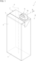
Figure 1 is a schematic perspective view of a package having a main body and an opening device according to the present invention, with parts removed for clarity; -
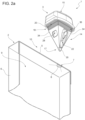
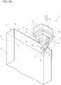
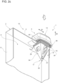
Figures 2a to 2c are schematic views on how to couple the opening device ofFigure 1 to the main body ofFigure 1 , with parts removed for clarity; -
Figure 3 is a perspective view of a portion of the opening device ofFigure 1 , with parts removed for clarity; -
Figure 4 is a sectioned view of the portion of the opening device ofFigure 3 , with parts removed for clarity; -
Figure 5 is a perspective view of the opening device ofFigure 1 with a detail being in an open position, with parts removed for clarity; -
Figure 6 is a perspective view of a detail of the opening device ofFigure 1 , with parts removed for clarity; and -
Figure 7 is a perspective view of an opening device according to a second embodiment of the present invention, with parts removed for clarity; -
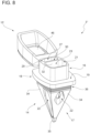
Figure 8 is a perspective view of an opening device according to a third embodiment of the present invention, with parts removed for clarity; -
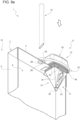
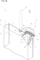
Figures 9a to 9c are perspective views of an opening device according to a fourth embodiment of the present invention partially coupled to the main body of a package and while coupling another portion of the opening device to the main body, with parts removed for clarity; and -
Figure 10 is a view of a package comprising an opening device according to a fifth embodiment of the present invention. -
Reference numeral 1 indicates as a whole a package comprising amain body 2 and areusable opening device 3 removably and/or releasably coupled to or removably and/or releasably couplable tomain body 2. - Preferentially,
main body 2 may be filled with a pourable product, more preferentially a pourable food product, such as water, pasteurized milk, milk products, yoghurt, yoghurt drinks, fruit juice, other kind of beverages, sauces, salt, sugar or the like. -
Package 1, preferentiallymain body 2, may be obtained from a multilayer packaging material having a multilayer structure (not shown). - The multilayer packaging material may comprise at least a layer of fibrous material, such as a paper or cardboard layer, and at least two layers of heat-seal plastic material, e.g. polyethylene, interposing the layer of fibrous material in between one another. One of these two layers of heat-seal plastic material may define an inner face of the
respective package 1, preferentially the respectivemain body 2, eventually contacting the pourable product. - Preferentially, the multilayer packaging material may also comprise a layer of gas- and light-barrier material, e.g. aluminum foil or ethylene vinyl alcohol (EVOH) film, in particular being arranged between one of the layers of the heat-seal plastic material and the layer of fibrous material. Preferentially, the multilayer packaging material may also comprise a further layer of heat-seal plastic material being interposed between the layer of gas- and light-barrier material and the layer of fibrous material.
- According to some preferred non-limiting embodiment, the multilayer packaging material may be provided in the form of a web or as single packaging blanks.
- In more detail, in case of the multilayer packaging material being provided in the form of a web, the web may define a plurality of repeat units successively arranged from one another. Preferentially, each repeat unit may define a respective precursor of one respective
main body 2. - With particular reference to
Figure 1 ,package 2 may extend along a longitudinal axis A. - In more detail,
package 2 may comprise afirst wall portion 4, preferentially being transversal, more preferentially perpendicular, to axis A and, from whichmain body 2 extends along axis A. Most preferentially,first wall portion 4 may define a support surface ofpackage 1, preferentiallymain body 2, which can be put in contact with a support, such as a shelf, e.g. when, in use, being exposed within a sales point or within a storage. -
First wall portion 4 may define a bottom wall ofpackage 1, preferentiallymain body 2, e.g. withpackage 1 being placed on the support and/or during an outpouring action of the pourable product frompackage 1. - Preferentially,
main body 2 may also comprise asecond wall portion 5 opposite tofirst wall portion 4. - Preferentially,
second wall portion 5 may define a top wall ofmain body 2, e.g. withpackage 1 being placed on the support and/or during an outpouring action of the pourable product frompackage 1. - As shown,
opening device 3 may be coupled tosecond wall portion 5. - According to the non-limiting example shown in
Figure 1 and2 ,first wall portion 4 andsecond wall portion 5 may be parallel to one another. - According to a non-limiting alternative embodiment,
second wall portion 5 could be inclined with respect tofirst wall portion 4. - Additionally,
package 1, preferentiallymain body 2, may also comprise aside wall 6 extending between along longitudinal axis A and betweenfirst wall portion 4 andsecond wall portion 5. Preferentially,side wall 6 may be connected tofirst wall portion 4 andsecond wall portion 5. - With particular reference to
Figures 2a and2b ,package 1, preferentiallymain body 2, comprises a designated pour opening surface area 7 (only partially shown). Preferentially, pour openingsurface 7 is configured to be opened and/or ruptured and/or cut so as to allow for the out-pouring of the pourable product frommain body 2. - More preferentially, pour
opening surface area 7 may comprise aseparation membrane 8 covering a hole ofmain body 2 and being configured to be ruptured. - Preferentially,
separation membrane 8 may be configured to separate aninner space 9 ofmain body 2 from anouter space 10. - According to some possible non-limiting embodiment,
separation membrane 8 may comprise a gas- and light-barrier material, e.g. aluminum foil or a film comprising ethylene vinyl alcohol (EVOH). - According to a preferred non-limiting embodiment,
separation membrane 8 may be defined by a portion of the multilayer packaging material, preferentially a portion of the layers of the web of packaging material being different from the layer of fibrous material. - Preferentially, pour
opening surface area 7 may be provided onsecond wall portion 5. - According to the specific embodiment shown, pour
opening surface area 7 may also comprise a plurality of weakening lines configured to break during the action ofopening device 3. -
Opening device 3 may be configured to be partially placed withinpackage 1, preferentiallymain body 2. - In particular,
opening device 3 can be removably connected topackage 1, preferentiallymain body 2, more particular such that after use a user can detachopening device 3 frommain body 2 and attachopening device 3 to a newmain body 2. - In this way, one avoids to provide an opening device on each
main body 2, which needs to be discharged together withmain body 2. -
Opening device 3 can be used on manymain bodies 2 thereby allowing for an overall reduction of plastic consumption. -
Opening device 3 may be configured to rupture designated pouropening surface area 7, preferentiallyseparation membrane 8. - With particular reference to
Figures 2a to 6 ,opening device 3 may comprise amain structure 14 configured to be removably coupled tomain body 2. Preferentially,main structure 14 may extend along a longitudinal axis B. - Preferentially,
opening device 3 may also comprise aclosing element 15 coupled and/or couplable tomain structure 14. - According to some preferred non-limiting embodiments,
opening device 3, preferentiallymain structure 14, may comprise: - an
outer body 16 configured to be arranged and/or being arranged outside ofpackage 1, preferentiallymain body 2, in particular with openingdevice 3 being coupled tomain body 2; and - a piercing
body 17 configured to pierce designated pour openingsurface area 7,preferentially separation membrane 8, and to be placed within or insidepackage 1, preferentiallymain body 2. - Preferentially,
opening device 3, preferentially piercingbody 17, may be configured to pierce designated pour openingsurface area 7,preferentially separation membrane 8, by means of and/or during a translatory movement along a linear axis, and preferentially without any rotational movement. - In other words, with
opening device 3 being coupled tomain body 2,outer body 16 is arranged inouter space 10 and piercingbody 17 is arranged ininner space 9. - Additionally,
opening device 3 may comprise anintermediate body 18 interposed betweenouter body 16 and piercingbody 17. - In more detail,
intermediate body 18 may comprise afirst face 19 and asecond face 20 opposite tofirst face 19. - Furthermore,
outer body 16 may protrude fromfirst face 19 and piercingbody 17 may protrude fromsecond face 20. Moreover,outer body 16 and piercingbody 17 may protrude in opposite directions fromintermediate body 18, along longitudinal axis B. -
Opening device 3, preferentiallyouter body 16, may comprise anoutlet opening 21 configured to allow for an outpouring of the pourable product frompackage 1. - Additionally, piercing
body 17 may carry and/or comprise at least oneinlet opening 22, preferentially a plurality ofinlet openings 22, in the specific case shown three. -
Opening device 3, preferentiallymain structure 14, comprises aflow channel 23 extending between inlet opening(s) 22 orinlet openings 22. - In particular, each inlet opening 22 being configured to allow for the pourable product entering flow channel 23 (with piercing
body 17 being placed within main body 2) and outlet opening 22 being configured to allow for the outflow of the pourable product out of flow channel 23 (and out of main structure 14). - In more detail,
flow channel 23 may comprise a first section being arranged within piercingbody 17 and a second section being arranged withinouter body 16. - Additionally, flow
channel 23 may comprise an intermediate section interposed between the first section and the second section and being arranged withinintermediate body 18. - According to some preferred non-limiting embodiments,
main structure 14 may be formed as a single piece, e.g.main structure 14 may be molded or 3D printed as a single piece. - According to some preferred non-limiting embodiments,
opening device 3 may also comprise anauxiliary channel 27 configured to allow for an air flow betweenouter space 10 andinner space 9. In this way, one allows to improve the flow of the pourable product withinflow channel 23 and out ofoutlet opening 21. -
Auxiliary channel 27 may comprise and/or extend between afirst opening 28 and asecond opening 29. - According to some possible embodiments,
second opening 29 may be arranged adjacent tooutlet opening 21. - According to the example shown in
Figures 2a to 6 ,main structure 14 may comprise auxiliary channel 24. - In more detail,
outer body 16 may comprisesecond opening 29 and/or piercingbody 17 may comprisefirst opening 28. - According to some preferred non-limiting embodiments,
main structure 14 may comprise anintermediate wall 30separating flow channel 23 andauxiliary channel 27 from one another. Preferentially,intermediate wall 30 may extend parallel to longitudinal axis B. - More specifically,
intermediate wall 30 may comprise a first portion 31 and asecond portion 32 located and/or extending within, respectively, piercingbody 17 andouter body 16. - Additionally,
intermediate wall 30 may also comprise anintermediate body 33 interposed between first portion 31 andsecond portion 32 and being located and/or extending withinintermediate body 18. - In further detail,
auxiliary channel 27 may comprise a first zone and a second zone extending within, respectively, piercingbody 17 andouter body 16. - Additionally,
auxiliary channel 27 may also comprise an intermediate zone interposed and extending between first zone and second zone. - Preferentially, the first section may be separated from the first zone by means of first portion 31 and the second section is separated from the second zone by means of
second portion 32. - Moreover, the intermediate section may be separated from the intermediate zone by means of
intermediate portion 33. - With particular reference to
Figures 2a to 6 , piercingbody 17 may comprises a plurality ofwalls 34 being arranged as a pyramid and/or such to define a pyramid-shape. - According to the specific example shown, piercing
body 17 may comprise fourwalls 34. Alternatively, piercingbody 17 may comprise threewalls 34 or even more than four. - It should be noted that the Applicant has observed to obtain excellent performances with piercing
bodies 17 having three or fourwalls 34. - In more detail, at least one of
walls 34 may compriseinlet opening 22. Preferentially, more than onewall 34 may comprise arespective inlet opening 22. - According to the specific embodiment shown, one of the
walls 34 may comprisefirst opening 28, and preferentially each one of theother walls 34 may comprise onerespective inlet opening 22. - In more detail, the
wall 34 comprisingfirst opening 28 may delimit together with first portion 31 the first zone ofauxiliary channel 27. - According to some preferred non-limiting embodiments, piercing
body 17 may comprise atip 35, preferentiallywalls 34 may extend towardstip 35. Preferentially, eachwall 34 may present a substantially triangular-shape tapering towardstip 35. -
Preferentially tip 35 may have a rounded shape. The Applicant has found that providing a piercingbody 17 with arounded tip 35 significantly reduces the risk of a user hurting him- or herself during use ofopening device 3. - According to some preferred non-limiting embodiments, piercing
body 17 may also comprise abase 36, more preferentially connected to and protruding fromintermediate body 18, along longitudinal axis B. - In more detail,
walls 34 may extend frombase 36 towardstip 35. - In further detail,
base 36 may comprise a plurality of delimitingwalls 37, each one extending fromintermediate body 18. - Preferentially, delimiting
walls 37 andwalls 34 may describe, respectively, a first angle and a second angle with respect to longitudinal axis B. More preferentially, the second angle may be different from the first angle. Even more preferentially, the first angle may be larger than the second angle. - With particular reference to
Figures 2a to 6 ,opening device 3 may comprise anengagement surface 40 configured to engage a rim ofmain body 2 delimiting designated pour openingarea 7. In particular,engagement surface 40 may be configured such that interaction betweenengagement surface 40 and the rim is such thatopening device 3 is connected tomain body 2 by friction. In this way, one avoids spillage of the pourable product betweenopening device 3 andmain body 2. Additionally,opening device 3 may not accidentally detach frommain body 2 and a user needs to exert a certain force on openingdevice 3 in order to removeopening device 3 frommain body 2. - Preferentially,
opening device 3 may comprise a sealing layer havingengagement surface 40. E.g. sealing layer may be of another material thanmain structure 14 for example rubber or silicon. - Preferentially, the sealing layer may be configured to seal an interface defined between the rim of
main body 2 andopening device 3. - Preferentially, the sealing layer may be connected to
main structure 14, e.g. to piercingbody 17 and/orintermediate body 18. - According to the example shown, at least a portion of the sealing layer may be applied to delimiting
walls 37, and preferentially another portion may be applied tosecond face 20. - According to some preferred non-limiting embodiments, the rim may form and/or evolve during the insertion of piercing
body 17 intomain body 2. Moreover, the shape of the rim may be defined by piercingbody 17 and/or the weakening lines and/or the hole covered byseparation membrane 8. - In further detail and with particular reference to
Figures 3 to 6 ,outer body 16 may comprise acollar 41, preferentially extending fromintermediate body 18. In detail,collar 41 may extend parallel to and/or about longitudinal axis B. - Preferentially,
collar 41 may at least delimitoutlet opening 21 and/or the second section offlow channel 23. - More preferentially,
collar 41 may delimit together withintermediate wall 30, in particularsecond portion 32, outlet opening 21 andsecond opening 29 and/or the second section offlow channel 23 and the second zone ofauxiliary channel 27. - According to some preferred non-limiting embodiments,
outer body 16, preferentiallycollar 41, may comprise a delimiting rim 47 at least partially delimitingoutlet opening 21, preferentially alsosecond opening 29. - In more detail, delimiting rim 47 delimits
outlet opening 21 andsecond opening 29 in collaboration with reinforcingwall 30. - Preferentially, delimiting rim 47 may lie within a plane.
- Preferentially, the plane may be transversal to longitudinal axis B, and more preferentially thereby not being perpendicular to longitudinal axis B.
- Most preferentially, the plane may define together with longitudinal axis an angle ranging between 3° to 15°, preferably between 3° to 10°, more preferably between 3° to 7°. According to the example shown, the angle is 5°.
- In other words, a distance of delimiting rim 47 to
first face 19 is a function of the annular position on delimiting rim 47. - In even other words, delimiting rim 47 and/or the plane may be inclined with respect to
first face 19 and/or longitudinal axis B. - With particular reference to
Figures 1 to 2c and5 , closingelement 15 may be selectively controllable into a closed position (seeFigures 1 to 2c and an open position (Figure 5 ) at which closingelement 15 may be configured to, respectively, close and open outlet opening 21, and preferentially alsosecond opening 29. - According to the embodiment of
Figures 1 to 6 , closingelement 15 may be slidingly engaged toouter body 16, preferentiallycollar 41, and may be linearly moveable into a sliding direction D1 between the closed position and the open position. - Preferentially,
outer body 16, morepreferentially collar 41, may comprise a pair of (linear) tracks 42 and closingelement 15 may comprise a pair ofgrooves 43, each one slidingly engaging onerespective track 42. In particular, interaction betweentracks 42 andgrooves 43 may define sliding direction D1. - In particular, closing
element 15 may slide transversally, preferentially perpendicularly, with respect to longitudinal axis B. In other words, sliding direction D1 may be transversal, preferentially perpendicular, to longitudinal axis B. - Alternatively, closing
element 15 may comprisegrooves 43 andouter body 16, preferentiallycollar 41, may comprise tracks 42. - With particular reference to
Figures 3 and6 , closingelement 15 may comprise afirst interaction element 44 andouter body 16, preferentiallycollar 41, may comprise asecond interaction element 45. - In the specific case shown,
first interaction element 44 may protrude from an inner face of closingelement 15 and/or may be formed as a T. - Additionally, in the specific case shown,
second interaction element 45 may be a groove, e.g. a groove having a T-shape, and preferentially being complementary tofirst interaction element 44. - According to some preferred non-limiting embodiments, closing
element 15 may comprise one ormore sealing elements 46 configured to engageouter body 16 and to sealoutlet opening 21 and/orsecond opening 29 with closingelement 15 being in the closed position. In particular, each sealingelement 46 may protrude from an inner face of closingelement 15 and/or the inner face may carry sealing element(s) 46. -
First interaction element 44 andsecond interaction element 45 may be configured to engage with one another with closingelement 15 being in the closed position and such to impede a movement of closingelement 15 into a direction D2 transversal to sliding direction D1. In this way, one guarantees that closingelement 15 correctly sits onouter body 16. This is in particular advantageous if closingelement 15 comprises one ormore sealing elements 46 asfirst interaction element 44 andsecond interaction element 45 guarantee the sealing effect of sealingelements 46. - With particular reference to
Figures 3 ,5 and 6 ,opening device 3 may comprise a first locking group configured to lock closingelement 15 in the closed position. In this way, one guarantees that no undesired sliding movement of closingelement 15 may occur, which may compromise e.g. a sealing effect of at leastoutlet opening 21. - Additionally or alternatively, the one or
more sealing elements 46 may interact with delimiting ring 47. Preferentially, by having delimiting ring 47 and/or the plane being inclined with respect tofirst face 19 and/or longitudinal axis B it is possible to improve locking of closingelement 15 in the closed position. - More preferentially, a distance of delimiting ring 47 with respect to
first face 19 increase into sliding direction D1 with respect to movement of closingelement 15 from the open position to the closed position. - Additionally or alternatively,
opening device 3 may comprise a second locking group configured to lock closingelement 15 in the open position. In this way, one impedes that closingelement 15 detaches fromouter body 16. - Preferentially, the first locking group and the second locking group may be partially associated to
outer body 16, preferentiallycollar 41, and partially associated to closingelement 15. - Closing
element 15 may comprise one ormore engagement elements 49, in particular two, configured to engagerespective surface portions 50 ofouter body 16 with closingelement 15 being in the closed position and such that movement of closingelement 15 becomes possible only after disengagingengagement element 49 from the surface portion. - Accordingly, the first locking group may comprise
surface portions 50 andengagement elements 49. - Preferentially, closing
element 15 may comprise one ormore slits 51, in particular two, andouter body 16 may compriserespective protrusion elements 52, each one being configured to engage into onerespective slit 51 with closingelement 15 being in the open position. In particular, thereby any further movement of closingelement 15 which would lead to closingelement 15 detaching fromouter body 16 byprotrusion elements 52 engaging into therespective slits 51. - With particular reference to
Figure 5 , closingelement 15 comprises anouter face 53 facing away fromouter body 16, preferentially with closingelement 15 being in the closed position. - Preferentially,
outer face 53 may be opposed to the inner face of closingelement 15, the inner face facing outlet opening 21 and/orsecond opening 29, in particular with closingelement 15 being in the closed position. - According to some preferred non-limiting embodiments,
outer face 53 may comprise at least a curved portion, in particular such that in case that a user wanted to placeouter face 53 onto a planar surface (e.g. a table, a working area in a kitchen, or the like),opening device 3 as a hole would fall sideways. In this manner, one reduces the risk of a user getting hurt by piercingbody 17 pointing upwards. - The use of
opening device 3 will be explained by particular reference toFigures 2a to 2c .Package 1, preferentiallymain body 2, has an intact designated pour openingarea 7, preferentially anintact separation membrane 8. The user getsopening device 3, approaches piercingbody 17 towards designated pour openingarea 7 and starts to pierce designated pour openingarea 7 by means of piercing body 17 (seeFigures 2a to 2b ). By further pressing piercingbody 17 intoinner space 9, at somepoint engagement surface 40 engages with the rim ofmain body 2 andopening device 3 is blocked tomain body 2 by means of friction (seeFigure 2c ) . - In further detail,
opening device 3 is configured to be coupled tomain body 2 by positioning openingdevice 3 with its longitudinal axis B parallel to longitudinal axis A ofmain body 2; thereafter pushingopening device 3 towards the designated pour openingarea 7 in a direction parallel to longitudinal axis B and/or longitudinal axis A, until piercingbody 17 pierces designated pour openingarea 7 and then keep advancingopening device 3 parallel to longitudinal axis B and/or longitudinal axis A untilengagement surface 40 engages with the rim ofmain body 2. - During use, the user may selectively control closing
element 15 between the closed position and the open position. - If desired (e.g. after fully emptying main body 2) it is possible to remove
opening device 3 frommain body 2, preferentially to cleanopening device 2, and to removably applyopening device 3 to a newmain body 2. In order to removeopening device 3, the user needs to pull it in a direction parallel to longitudinal axis B and/or longitudinal axis A, away frommain body 2. - With reference to
Figure 7 ,number 3" indicates an alternative embodiment of an opening device according to the present invention; as openingdevice 3" is similar toopening device 3, the following description is limited to the differences between them, and using the same references, where possible, for identical or corresponding parts. - Opening device 3' differs from opening
device 3 in that the respective closing element (not shown) is moveable between the respective closed position and the open position by a movement along a direction parallel to longitudinal axis B. - Alternatively, opening device 3' may also be void of a closing element.
- Use of opening device 3' is similar to the use of
opening device 3 with the difference that control of closingelement 15 does not rely on a sliding movement but relies on moving theclosing element 15 along the direction parallel to longitudinal axis B. In this embodiment, closingelement 15 when being in the open position may be disconnected frommain structure 14. - With reference to
Figure 8 ,number 3" indicates an alternative embodiment of an opening device according to the present invention; as openingdevice 3" is similar toopening device 3, the following description is limited to the differences between them, and using the same references, where possible, for identical or corresponding parts. -
Opening device 3" differs from openingdevice 3 in thatclosing element 15 is moveable between the closed position and the open position by means of an angular movement of closingelement 15 about a hinge axis, preferentially being transversal, more preferentially perpendicular, to longitudinal axis B. In this embodiment, closingelement 15 may be connected to themain structure 14 by a hinge connection that allows movement of closing element 15 (only) along the hinge axis, between the closed position and the open position. Therefore, closingelement 15 cannot be dispersed when being in the open position. - Use of opening
device 3" is similar to the use ofopening device 3 with the difference that control of closingelement 15 does not rely on a sliding movement but relies on an angular movement about the hinge axis. - With reference to
Figures 9a to 9c ,number 3‴ indicates an alternative embodiment of an opening device according to the present invention; as openingdevice 3‴ is similar toopening device 3, the following description is limited to the differences between them, and using the same references, where possible, for identical or corresponding parts. -
Opening device 3‴ differs from openingdevice 3 in comprising atubular structure 57 carrying and/or comprisingauxiliary channel 27. - More specifically,
tubular structure 57 may be spaced apart frommain structure 14. In particular,main structure 14 does not compriseauxiliary channel 27 butauxiliary channel 27 is provided in a physical separate portion ofopening device 3‴, namelytubular structure 57. - Moreover,
tubular structure 57 may be configured to be partially placed withinmain body 2. - Moreover,
main body 2 may comprise a further piercing area having afurther separation membrane 58. -
Tubular structure 57 may be configured to pierce the further piercing area, preferentiallyfurther separation membrane 58. - Additionally,
opening device 3‴ may comprise asupport frame 59 laterally protruding frommain structure 14, preferentiallyintermediate body 18, and preferentially being configured to abut againstmain body 2, preferentiallysecond wall portion 5. - Preferentially,
support frame 59 may comprise ahole 60, which is configured to be aligned with the piercing area. - In the specific embodiment of
Figures 9a to 9c ,tubular structure 57 is separate frommain structure 14 andsupport frame 59. - In use, while one intends to insert
tubular structure 57 intoinner space 9,tubular structure 57 needs also to be move throughhole 60. Therefore,hole 60 may also be configured to allow for guidingtubular structure 57 while introducingtubular structure 57 intoinner space 9. - In the specific embodiment of
Figures 9a to 9c ,opening device 3" ' comprises closingelement 15 of the embodiment ofFigures 1 to 6 (of opening device 3). - Alternatively,
opening device 3" ' could comprise closingelement 15 ofopening device 3" ofFigure 8 or the closing element of opening device 3' ofFigure 7 . -
Figures 9a and9c show the use ofopening device 3‴, which differs from the use ofopening device 3 in that after applyingmain portion 14 andsupport frame 59 onmain body 2,tubular structure 57 needs to be partially inserted intoinner space 9. - This is done by approaching
tubular structure 57 to hole 60 and to presstubular structure 57 through the piercing area. - With reference to
Figure 10 , number 3ʺʺ indicates an alternative embodiment of an opening device according to the present invention; as opening device 3ʺʺ is similar toopening device 3‴, the following description is limited to the differences between opening device 3ʺʺ andopening device 3‴ andpackage 2‴, and using the same references, where possible, for identical or corresponding parts. - In particular, opening device 3ʺʺ differs from opening
device 3" ' in thattubular structure 57 is fixedly connected to supportframe 59. In particular,tubular structure 57 cannot move neither with respect to supportframe 59 nor with respect tomain structure 14. In this embodiment,main structure 14 andsupport frame 59 may be realized as a single piece. - Use of opening device 3ʺʺ differs from use of
opening device 3" ' in thattubular structure 57 is introduced intoinner space 9 substantially together with introducing of piercingbody 17 intoinner space 9. - The advantages of
packages 2 and 2''' and/or ofopening device - In particular, opening
devices main bodies 2, which allows to avoid providing respective open devices on eachmain body 2. This should allow to reduce plastic consumption. - Clearly, changes may be made to package 2 and 2‴ and/or
opening device
Claims (17)
- Reusable opening device (3, 3', 3", 3‴, 3ʺʺ) for a package (1) filled with a pourable product and having a designated pour opening surface area (7);the opening device (3, 3', 3", 3‴, 3ʺʺ) being configured to be removably connected to a main body (2) of the package (1) and comprising:- an outer body (16) configured to be placed outside of the main body (2) and having an outlet opening (21) configured to allow for an outpouring of the pourable product; and- a piercing body (17) configured to pierce the designated pour opening surface area (7) and to be placed within the package (2);wherein the opening device (3, 3', 3'', 3‴, 3ʺʺ) comprises a flow channel (23) extending between at least one inlet opening (22) and the outlet opening (21);wherein the piercing body (17) carries and/or comprises the inlet opening (22), the inlet opening (22) allowing the inlet of the pourable product into the flow channel (23).
- Opening device according to claim 1, further comprising an auxiliary channel (27) configured to allow for an air flow between an outer space (10) and an inner space (9) of the main body (2).
- Opening device according to claim 2, wherein the opening device (3, 3ʺ) comprises a main structure (14) comprising the outer body (16), the piercing body (17) and the flow channel (23);wherein the main structure (14) also comprises the auxiliary channel (27) and an intermediate wall (30) separating the flow channel (23) and the auxiliary channel (27) from one another; orthe opening device (3‴, 3ʺʺ) further comprises a tubular structure (57) spaced apart from the main structure (14) and having the auxiliary channel (27) and being configured to be partially placed within the main body (2).
- Opening device according to claim 2 or 3, wherein the auxiliary channel (27) comprises a first zone extending within the piercing body (17) and a second zone extending within the outer body (16).
- Opening device according to claim 4, wherein the flow channel (23) comprises a first section and a second section extending, respectively, within the piercing body (17) and the outer body (16);
wherein the first section is separated from the first zones by means of a first portion (31) of the intermediate wall (30) and the second section is separated from the second zone by means of a second portion (32) of the intermediate wall (30). - Opening device according to any one of claims 2 to 5, wherein the auxiliary channel (27) comprises and extends between a first opening (28) and a second opening (29); wherein the first opening (28) is configured to be placed within the main body (2) and the second opening (29) is configured to be arranged outside from the main body(2);
wherein the second opening (28) is adjacent to the outlet opening (21) and/or is carried by the outer body (16) . - Opening device according to any one of the preceding claims, wherein the piercing body (17) comprises a plurality of walls (34) being arranged to form a pyramid and/or such to define a pyramid-shape;
wherein at least one of the walls (34) comprises the inlet opening (28) and/or more than one of the walls (34) comprises a respective inlet opening (28). - Opening device according to any one of the preceding claims, wherein the piercing body (17) comprises a tip (35);
wherein the tip (35) presents a rounded-shape. - Opening device according to any one of the preceding claims, further comprising an engagement surface (40) configured to engage a rim delimiting the designated pour opening surface area (7).
- Opening device according to claim 9, comprising a sealing layer having the engagement surface (40);
the sealing layer being configured to seal an interface defined between the rim and the opening device (3, 3', 3", 3‴, 3ʺʺ). - Opening device according to claim 3 and 10, wherein the sealing layer is made of another material than a material in which the main structure (14) is made,wherein the piercing body (17) comprises a base (36) and a plurality of walls (34), the walls (34) extending from the base (36) and being arranged as a pyramid and/or such to define a pyramid-shape,wherein the base (36) comprises a plurality of delimiting walls (37),wherein the opening device (3) further comprises an intermediate body (18) interposed between the outer body (16) and the piercing body (17), the intermediate body (18) comprising a first face (19) and a second face (20) opposite to the first face (19),wherein at least a portion of the sealing layer is applied to the delimiting walls (37) of the base (36), and another portion of the sealing layer is applied to the second face (20) of the intermediate body (18).
- Opening device according to any one of the preceding claims, further comprising a closing element (15) selectively controllable into a closed position and an open position at which the closing element is configured to, respectively, close and open the outlet opening (21).
- Opening device according to claim 12, wherein the closing element (15) is slidingly engaged to the outer body (16) and is linearly moveable into a sliding direction (D1) between the closed position and the open position.
- Opening device according to claim 13, wherein the closing element (15) comprises a first interaction element (44) and the outer body (16) comprises a second interaction element (45);
wherein the first interaction element (44) and the second interaction element (45) being configured to engage with one another with the closing element (15) being in the closed position and such to impede a movement of the closing element (15) into a direction transversal to the sliding direction (D1). - Opening device according to claim 13 or 14, comprising a first locking group configured to lock the closing element (15) in the closed position and/or a second locking group configured to lock the closing element (15) in the open position.
- Opening device according to any one of claims 13 to 15, wherein the closing element (15) comprises an outer face (53) facing away from the outer body (16);
wherein the outer face (53) comprises at least a curved portion. - Package (1) for a pourable product comprising a main body (2) formed from a multilayer packaging material and a reusable opening device (3, 3', 3", 3‴, 3ʺʺ) according to any one of the preceding claims.
Applications Claiming Priority (1)
| Application Number | Priority Date | Filing Date | Title |
|---|---|---|---|
| IT202300007896 | 2023-04-21 |
Publications (1)
| Publication Number | Publication Date |
|---|---|
| EP4450418A1 true EP4450418A1 (en) | 2024-10-23 |
Family
ID=87036884
Family Applications (1)
| Application Number | Title | Priority Date | Filing Date |
|---|---|---|---|
| EP24170131.7A Pending EP4450418A1 (en) | 2023-04-21 | 2024-04-15 | Reusable opening device for a package and package having a reusable opening device |
Country Status (2)
| Country | Link |
|---|---|
| EP (1) | EP4450418A1 (en) |
| WO (1) | WO2024218024A1 (en) |
Citations (11)
| Publication number | Priority date | Publication date | Assignee | Title |
|---|---|---|---|---|
| FR1113208A (en) * | 1954-10-26 | 1956-03-26 | Removable spout for containers | |
| CH405971A (en) * | 1963-07-12 | 1966-01-15 | Herrmann Ernst | Can pourer |
| DE2410773A1 (en) * | 1974-03-07 | 1975-09-11 | Hesser Ag Maschf | Stick-in dispenser for containers - has entry in tube between pyramid tip and top flange of tubular shaft |
| JPS54134155U (en) * | 1978-03-06 | 1979-09-18 | ||
| BE903007A (en) * | 1985-08-01 | 1985-12-02 | Shortall John Francis | Spout for emptying fluids from thin walled container - has integral air vent adjacent to mounting to assist even pouring |
| WO1992000883A1 (en) * | 1990-07-05 | 1992-01-23 | Jung Min Lee | Carton pack attached with built-in plug |
| US5405034A (en) * | 1992-04-24 | 1995-04-11 | Mittel, Jr.; Joseph C. | Closure device |
| US5687885A (en) * | 1995-10-24 | 1997-11-18 | Minnesota Mining And Manufacturing Co. | Dispensing container and sliding cap assembly |
| JP5270472B2 (en) * | 2009-06-30 | 2013-08-21 | 株式会社吉野工業所 | Liquid container spout |
| JP2016074434A (en) * | 2014-10-02 | 2016-05-12 | 大日本印刷株式会社 | Injection tool and container |
| US10280058B1 (en) * | 2018-08-08 | 2019-05-07 | Cloud Candy, Llc | Container tapping device |
-
2024
- 2024-04-15 EP EP24170131.7A patent/EP4450418A1/en active Pending
- 2024-04-15 WO PCT/EP2024/060111 patent/WO2024218024A1/en not_active Ceased
Patent Citations (11)
| Publication number | Priority date | Publication date | Assignee | Title |
|---|---|---|---|---|
| FR1113208A (en) * | 1954-10-26 | 1956-03-26 | Removable spout for containers | |
| CH405971A (en) * | 1963-07-12 | 1966-01-15 | Herrmann Ernst | Can pourer |
| DE2410773A1 (en) * | 1974-03-07 | 1975-09-11 | Hesser Ag Maschf | Stick-in dispenser for containers - has entry in tube between pyramid tip and top flange of tubular shaft |
| JPS54134155U (en) * | 1978-03-06 | 1979-09-18 | ||
| BE903007A (en) * | 1985-08-01 | 1985-12-02 | Shortall John Francis | Spout for emptying fluids from thin walled container - has integral air vent adjacent to mounting to assist even pouring |
| WO1992000883A1 (en) * | 1990-07-05 | 1992-01-23 | Jung Min Lee | Carton pack attached with built-in plug |
| US5405034A (en) * | 1992-04-24 | 1995-04-11 | Mittel, Jr.; Joseph C. | Closure device |
| US5687885A (en) * | 1995-10-24 | 1997-11-18 | Minnesota Mining And Manufacturing Co. | Dispensing container and sliding cap assembly |
| JP5270472B2 (en) * | 2009-06-30 | 2013-08-21 | 株式会社吉野工業所 | Liquid container spout |
| JP2016074434A (en) * | 2014-10-02 | 2016-05-12 | 大日本印刷株式会社 | Injection tool and container |
| US10280058B1 (en) * | 2018-08-08 | 2019-05-07 | Cloud Candy, Llc | Container tapping device |
Also Published As
| Publication number | Publication date |
|---|---|
| WO2024218024A1 (en) | 2024-10-24 |
Similar Documents
| Publication | Publication Date | Title |
|---|---|---|
| EP4234424B1 (en) | Spout for a container and package-spout assembly | |
| EP3892563A1 (en) | Spout for a package, lid-spout assembly for a package and package having a spout | |
| EP3892564B1 (en) | Lid-spout assembly for a package | |
| US12473123B2 (en) | Lid-spout assembly for a package and package having a lid-spout assembly | |
| EP4299460B1 (en) | Opening device for a package and package therewith | |
| EP3663220B1 (en) | Package | |
| EP4159402B1 (en) | Opening device for a package, mold for molding an opening device for a package and package having an opening device | |
| EP4159634B1 (en) | Opening device for a package, mold for molding an opening device for a package and package having an opening device | |
| WO2024218024A1 (en) | Reusable opening device for a package and package having a reusable opening device | |
| EP4299459A1 (en) | Opening device for a package and package therewith | |
| EP4124584A1 (en) | Opening device for a package and package having an opening device | |
| EP4617193A1 (en) | Reusable opening device for a package and package having a reusable opening device | |
| EP4124585B1 (en) | Opening device for a package and package | |
| EP4606728A1 (en) | Closure for an opening device, opening device for a package and package | |
| EP4480842A2 (en) | Opening device for a package, mold for molding an opening device and package having an opening device | |
| EP4606727A1 (en) | Closure for an opening device, opening device for a package and package | |
| EP4592209A1 (en) | Opening device for a package and package | |
| CN117120338A (en) | Packaging to contain food products and molds for packaging machines |
Legal Events
| Date | Code | Title | Description |
|---|---|---|---|
| PUAI | Public reference made under article 153(3) epc to a published international application that has entered the european phase |
Free format text: ORIGINAL CODE: 0009012 |
|
| STAA | Information on the status of an ep patent application or granted ep patent |
Free format text: STATUS: THE APPLICATION HAS BEEN PUBLISHED |
|
| AK | Designated contracting states |
Kind code of ref document: A1 Designated state(s): AL AT BE BG CH CY CZ DE DK EE ES FI FR GB GR HR HU IE IS IT LI LT LU LV MC ME MK MT NL NO PL PT RO RS SE SI SK SM TR |
|
| STAA | Information on the status of an ep patent application or granted ep patent |
Free format text: STATUS: REQUEST FOR EXAMINATION WAS MADE |
|
| 17P | Request for examination filed |
Effective date: 20250423 |
|
| STAA | Information on the status of an ep patent application or granted ep patent |
Free format text: STATUS: EXAMINATION IS IN PROGRESS |
|
| 17Q | First examination report despatched |
Effective date: 20250919 |
|
| STAA | Information on the status of an ep patent application or granted ep patent |
Free format text: STATUS: THE APPLICATION IS DEEMED TO BE WITHDRAWN |