EP4450339A2 - Variable airfoil profile hollow wiper arms - Google Patents
Variable airfoil profile hollow wiper arms Download PDFInfo
- Publication number
- EP4450339A2 EP4450339A2 EP24171673.7A EP24171673A EP4450339A2 EP 4450339 A2 EP4450339 A2 EP 4450339A2 EP 24171673 A EP24171673 A EP 24171673A EP 4450339 A2 EP4450339 A2 EP 4450339A2
- Authority
- EP
- European Patent Office
- Prior art keywords
- wiper
- arm
- wall thickness
- airfoil profile
- recited
- Prior art date
- Legal status (The legal status is an assumption and is not a legal conclusion. Google has not performed a legal analysis and makes no representation as to the accuracy of the status listed.)
- Pending
Links
Images


Classifications
-
- B—PERFORMING OPERATIONS; TRANSPORTING
- B60—VEHICLES IN GENERAL
- B60S—SERVICING, CLEANING, REPAIRING, SUPPORTING, LIFTING, OR MANOEUVRING OF VEHICLES, NOT OTHERWISE PROVIDED FOR
- B60S1/00—Cleaning of vehicles
- B60S1/02—Cleaning windscreens, windows or optical devices
- B60S1/04—Wipers or the like, e.g. scrapers
- B60S1/32—Wipers or the like, e.g. scrapers characterised by constructional features of wiper blade arms or blades
- B60S1/34—Wiper arms; Mountings therefor
- B60S1/3425—Constructional aspects of the arm
- B60S1/3431—Link pieces
-
- B—PERFORMING OPERATIONS; TRANSPORTING
- B60—VEHICLES IN GENERAL
- B60S—SERVICING, CLEANING, REPAIRING, SUPPORTING, LIFTING, OR MANOEUVRING OF VEHICLES, NOT OTHERWISE PROVIDED FOR
- B60S1/00—Cleaning of vehicles
- B60S1/02—Cleaning windscreens, windows or optical devices
- B60S1/04—Wipers or the like, e.g. scrapers
- B60S1/32—Wipers or the like, e.g. scrapers characterised by constructional features of wiper blade arms or blades
-
- B—PERFORMING OPERATIONS; TRANSPORTING
- B60—VEHICLES IN GENERAL
- B60S—SERVICING, CLEANING, REPAIRING, SUPPORTING, LIFTING, OR MANOEUVRING OF VEHICLES, NOT OTHERWISE PROVIDED FOR
- B60S1/00—Cleaning of vehicles
- B60S1/02—Cleaning windscreens, windows or optical devices
- B60S1/04—Wipers or the like, e.g. scrapers
- B60S1/32—Wipers or the like, e.g. scrapers characterised by constructional features of wiper blade arms or blades
- B60S1/34—Wiper arms; Mountings therefor
- B60S1/3425—Constructional aspects of the arm
-
- B—PERFORMING OPERATIONS; TRANSPORTING
- B60—VEHICLES IN GENERAL
- B60S—SERVICING, CLEANING, REPAIRING, SUPPORTING, LIFTING, OR MANOEUVRING OF VEHICLES, NOT OTHERWISE PROVIDED FOR
- B60S1/00—Cleaning of vehicles
- B60S1/02—Cleaning windscreens, windows or optical devices
- B60S1/04—Wipers or the like, e.g. scrapers
- B60S1/32—Wipers or the like, e.g. scrapers characterised by constructional features of wiper blade arms or blades
- B60S1/34—Wiper arms; Mountings therefor
- B60S1/3425—Constructional aspects of the arm
- B60S1/3427—Arm piece, link piece and mounting head formed as one element
-
- B—PERFORMING OPERATIONS; TRANSPORTING
- B60—VEHICLES IN GENERAL
- B60S—SERVICING, CLEANING, REPAIRING, SUPPORTING, LIFTING, OR MANOEUVRING OF VEHICLES, NOT OTHERWISE PROVIDED FOR
- B60S1/00—Cleaning of vehicles
- B60S1/02—Cleaning windscreens, windows or optical devices
- B60S1/04—Wipers or the like, e.g. scrapers
- B60S1/32—Wipers or the like, e.g. scrapers characterised by constructional features of wiper blade arms or blades
- B60S1/34—Wiper arms; Mountings therefor
- B60S1/3425—Constructional aspects of the arm
- B60S1/3431—Link pieces
- B60S1/3434—Manufacturing details thereof
-
- B—PERFORMING OPERATIONS; TRANSPORTING
- B60—VEHICLES IN GENERAL
- B60S—SERVICING, CLEANING, REPAIRING, SUPPORTING, LIFTING, OR MANOEUVRING OF VEHICLES, NOT OTHERWISE PROVIDED FOR
- B60S1/00—Cleaning of vehicles
- B60S1/02—Cleaning windscreens, windows or optical devices
- B60S1/04—Wipers or the like, e.g. scrapers
- B60S1/32—Wipers or the like, e.g. scrapers characterised by constructional features of wiper blade arms or blades
- B60S1/34—Wiper arms; Mountings therefor
- B60S1/3425—Constructional aspects of the arm
- B60S1/3436—Mounting heads
-
- B—PERFORMING OPERATIONS; TRANSPORTING
- B60—VEHICLES IN GENERAL
- B60S—SERVICING, CLEANING, REPAIRING, SUPPORTING, LIFTING, OR MANOEUVRING OF VEHICLES, NOT OTHERWISE PROVIDED FOR
- B60S1/00—Cleaning of vehicles
- B60S1/02—Cleaning windscreens, windows or optical devices
- B60S1/04—Wipers or the like, e.g. scrapers
- B60S1/32—Wipers or the like, e.g. scrapers characterised by constructional features of wiper blade arms or blades
- B60S1/34—Wiper arms; Mountings therefor
- B60S1/3425—Constructional aspects of the arm
- B60S1/3436—Mounting heads
- B60S1/3438—Manufacturing details thereof
-
- B—PERFORMING OPERATIONS; TRANSPORTING
- B60—VEHICLES IN GENERAL
- B60S—SERVICING, CLEANING, REPAIRING, SUPPORTING, LIFTING, OR MANOEUVRING OF VEHICLES, NOT OTHERWISE PROVIDED FOR
- B60S1/00—Cleaning of vehicles
- B60S1/02—Cleaning windscreens, windows or optical devices
- B60S1/04—Wipers or the like, e.g. scrapers
- B60S1/0408—Means for influencing the aerodynamic quality of wipers, e.g. clip-on wind deflectors
-
- B—PERFORMING OPERATIONS; TRANSPORTING
- B60—VEHICLES IN GENERAL
- B60S—SERVICING, CLEANING, REPAIRING, SUPPORTING, LIFTING, OR MANOEUVRING OF VEHICLES, NOT OTHERWISE PROVIDED FOR
- B60S1/00—Cleaning of vehicles
- B60S1/02—Cleaning windscreens, windows or optical devices
- B60S1/04—Wipers or the like, e.g. scrapers
- B60S1/32—Wipers or the like, e.g. scrapers characterised by constructional features of wiper blade arms or blades
- B60S1/34—Wiper arms; Mountings therefor
- B60S1/3425—Constructional aspects of the arm
- B60S1/3436—Mounting heads
- B60S1/344—Flat-type mounting heads
Definitions
- the present disclosure relates to wiper arms for windshield wipers, and more particularly to wiper arms for windshield wipers such as used on aircraft cockpits.
- a wiper apparatus includes a wiper axis interface configured for mounting a wiper assembly to a wiper drive.
- a lower wiper arm extends from the wiper axis interface to a wiper mount that is configured to connect the lower arm to an upper arm.
- a first end of the lower wiper arm proximate the wiper axis interface has a first airfoil profile.
- a second end of the lower wiper arm proximate the wiper mount has a second airfoil profile.
- An intermediate portion of the lower wiper arm extending between the first and second ends has a transitioning airfoil profile that transitions from the first airfoil profile to the second airfoil profile.
- the first airfoil profile can have a smaller maximum thickness than that of the second airfoil profile.
- the first airfoil profile can have ca longer chord line than that of the second airfoil profile.
- the lower wiper arm can define a curve so a first longitudinal axis of the lower wiper arm defined by the first end is oblique relative to a second longitudinal axis of the lower arm defined at the second end.
- the upper arm can be connected to the wiper mount.
- a bridge can be mounted to an end of the upper arm opposite the wiper mount.
- a wiper blade can be operatively connected to the bridge for wiping a windshield.
- the wiper axis interface can be mounted to the wiper drive so the wiper drive can drive the lower wiper arm with reciprocating motion about a rotation axis defined by the wiper axis interface.
- An outer wall of the lower wiper arm can be defined about a hollow core of the lower wiper arm. At the first end of the lower wiper arm, the outer wall can have a first wall thickness. At the second end of the lower wiper arm, the outer wall can have a second wall thickness different from the first thickness. Along the intermediate portion, the outer wall can have a transitioning wall thickness that transitions from the first wall thickness to the second wall thickness.
- the transitioning airfoil profile can transition smoothly from the first airfoil profile to the second airfoil profile.
- the first wall thickness can be thicker than the second wall thickness.
- the transitioning thickness can transition smoothly from the first wall thickness to the wall second thickness.
- the hollow core can terminate at a first bore opening into a connector bore of the wiper axis interface.
- the hollow core can terminate at a second bore opening into a clevis of the wiper mount.
- Fig. 1 a partial view of an embodiment of a wiper apparatus in accordance with the disclosure is shown in Fig. 1 and is designated generally by reference character 100.
- FIGs. 2-8 Other embodiments of systems in accordance with the disclosure, or aspects thereof, are provided in Figs. 2-8 , as will be described.
- the systems and methods described herein can be used to improve aerodynamics, weight, manufacturability, and overall performance of wiper arms and wiper systems such as for use on aircraft cockpit windshields.
- the wiper apparatus 100 includes a wiper axis interface 102 mounting the wiper assembly 104 to a wiper drive 106 (labeled in Fig. 2 ) of an aircraft 108.
- a lower wiper arm 110 extends from the wiper axis interface 102 to a wiper mount 112, which is in the form of a clevis, that is connects the lower arm 110 to an upper arm 114.
- a bridge 116 is mounted to an end of the upper arm 114 opposite the wiper mount 112.
- a wiper blade 118 is operatively connected to the bridge 116 for wiping the cockpit windshield 120. Referring to Fig.
- the wiper axis interface 102 is mounted to the wiper drive 106 so the wiper drive 106 can drive the lower wiper arm 110 (and therefore the entire wiper assembly 104) with reciprocating motion about a rotation axis A defined by the wiper axis interface 102.
- the reciprocating motion is in the direction of the double headed arrow 122 in Fig. 2 .
- a first end 124 of the lower wiper arm 110 proximate the wiper axis interface 102 has a first airfoil profile, i.e. the cross-section at the location indicated in Fig. 3 and shown in Fig. 4 .
- a second end 126 of the lower wiper arm 110 proximate the wiper mount 112 has a second airfoil profile, i.e. the cross section at the location indicated in Fig. 3 and shown in Fig. 5 .
- An intermediate portion 128 of the lower wiper arm 110 extends between the first and second ends 124, 126 and has a transitioning airfoil profile that transitions smoothly, i.e. continuously from the first airfoil profile shown in Fig.
- the lower wiper arm 110 defines a curve in the intermediate portion 128 so a first longitudinal axis L1 of the lower wiper arm defined by the first end is oblique relative to a second longitudinal axis of the lower arm defined at the second end, e.g. by an angle ⁇ of about 30-degrees but those skilled in the art will readily appreciate that any suitable angle ⁇ can be used without departing from the scope of this disclosure.
- Figs. 4 and 5 show the chord lengths C and the maximum thicknesses T for the first and second airfoil profiles.
- the portion of the lower arm 110 that is most transverse to the air flow direction indicated in Fig. 3 is the portion with the airfoil profile having the highest ratio C/T of chord length C to maximum chord thickness T, i.e. is the most streamlined portion to flow transverse to the airfoil.
- the ratio of C/T changes smoothly along the length of the intermediate portion 128.
- the portion of the lower arm 110 that is least transverse to the air flow direction indicated in Fig. 3 is the portion with the lowest ratio of C/T, i.e. the least streamlined portion to flow transverse to the airfoil.
- the first airfoil profile, shown in Fig. 4 has a smaller maximum thickness T than that of the second airfoil profile shown in Fig. 5 .
- the first airfoil profile shown in Fig. 4 has a longer chord line C than that of the second airfoil profile shown in Fig. 5 .
- the lower wiper arm 110 can be hollow, in which case an outer wall 130 of the lower wiper arm 110 is defined about a hollow core 132 of the lower wiper arm 110.
- the outer wall 130 has a first wall thickness W.
- the outer wall 130 has a second wall thickness W different from the first wall thickness.
- the outer wall 130 has a transitioning wall thickness W that transitions from the first wall thickness W to the second wall thickness W. This does not imply that each local thickness along the length is locally uniform in thickness, e.g.
- the transitioning wall thickness transitions smoothly, i.e. continuously, from the first wall thickness W to the second wall thickness W. Smooth transition for the wall thickness may not be required, e.g. provided all external surface transition is smoothly maintained.
- the first wall thickness W i.e. proximate the first end 124, is thicker than the second wall thickness W, i.e. proximate the second end 126. This thickness profile of the outer wall 130 allows for reduced weight relative to solid lower arm designs, while still providing the material strength where needed.
- the hollow core 132 terminates at a first bore 134 that opens into a connector bore 136 of the wiper axis interface 102, wherein the first bore 134 extends along the first longitudinal axis L1, as shown in Fig. 7 .
- the hollow core 132 of Fig. 3 also terminates at a second bore 136 opening into the clevis 138 of the wiper mount, and extends along the second longitudinal axis L2, as shown in Fig. 8 .
- the first and second bores 134, 136 allow draining of additive manufacturing stock powder out of the hollow core 132, labeled in Fig. 3 , after building the lower arm 110 in an additive manufacturing process.
- the hollow core 132 is not an open channel, but a hollow core completely surrounded by the outer wall 132 but for the first and second bores 134, 136 of Figs. 7-8 .
- the cross section of the lower arm can be optimized with an airfoil shape with much lower drag than traditional configurations. This lowers drag on the aircraft, e.g. for fuel economy, and reduces loading on the wiper apparatus as a whole, leading to longer system life.
- the lower wiper arm can be structurally optimized as the airfoil profile can be stiffer in the bending direction of the lower arm than in traditional configurations.
- the airfoil profile sizing can also be driven by structural need as the highest stressed areas near the wiper axis interface can have the highest cross-sectional area and wall thickness, and the airfoil area and wall thickness can be reduced closer to the wiper mount.
Landscapes
- Engineering & Computer Science (AREA)
- Mechanical Engineering (AREA)
- Manufacturing & Machinery (AREA)
- Body Structure For Vehicles (AREA)
- Structures Of Non-Positive Displacement Pumps (AREA)
- Transmission Devices (AREA)
Abstract
Description
- The present disclosure relates to wiper arms for windshield wipers, and more particularly to wiper arms for windshield wipers such as used on aircraft cockpits.
- Traditional aircraft windshield wiper arms for aircraft cockpits are manufactured from metallic materials such as stainless steels. They are sized for the loading of the wiper blade assembly during operation. Drag induced by this component affects the mechanical loading of the wiper system, which in turn drives the sizing of the wiper arm and life of the wiper system.
- The conventional techniques have been considered satisfactory for their intended purpose. However, there is an ever present need for improved systems and methods for wiper arms such as for use with aircraft cockpit windshields. This disclosure provides a solution for this need.
- A wiper apparatus includes a wiper axis interface configured for mounting a wiper assembly to a wiper drive. A lower wiper arm extends from the wiper axis interface to a wiper mount that is configured to connect the lower arm to an upper arm. A first end of the lower wiper arm proximate the wiper axis interface has a first airfoil profile. A second end of the lower wiper arm proximate the wiper mount has a second airfoil profile. An intermediate portion of the lower wiper arm extending between the first and second ends has a transitioning airfoil profile that transitions from the first airfoil profile to the second airfoil profile.
- The first airfoil profile can have a smaller maximum thickness than that of the second airfoil profile. The first airfoil profile can have ca longer chord line than that of the second airfoil profile. The lower wiper arm can define a curve so a first longitudinal axis of the lower wiper arm defined by the first end is oblique relative to a second longitudinal axis of the lower arm defined at the second end.
- The upper arm can be connected to the wiper mount. A bridge can be mounted to an end of the upper arm opposite the wiper mount. A wiper blade can be operatively connected to the bridge for wiping a windshield. The wiper axis interface can be mounted to the wiper drive so the wiper drive can drive the lower wiper arm with reciprocating motion about a rotation axis defined by the wiper axis interface.
- An outer wall of the lower wiper arm can be defined about a hollow core of the lower wiper arm. At the first end of the lower wiper arm, the outer wall can have a first wall thickness. At the second end of the lower wiper arm, the outer wall can have a second wall thickness different from the first thickness. Along the intermediate portion, the outer wall can have a transitioning wall thickness that transitions from the first wall thickness to the second wall thickness.
- The transitioning airfoil profile can transition smoothly from the first airfoil profile to the second airfoil profile. The first wall thickness can be thicker than the second wall thickness. The transitioning thickness can transition smoothly from the first wall thickness to the wall second thickness. The hollow core can terminate at a first bore opening into a connector bore of the wiper axis interface. The hollow core can terminate at a second bore opening into a clevis of the wiper mount.
- These and other features of the systems and methods of the subject disclosure will become more readily apparent to those skilled in the art from the following detailed description of the preferred embodiments taken in conjunction with the drawings.
- So that those skilled in the art to which the subject disclosure appertains will readily understand how to make and use the devices and methods of the subject disclosure without undue experimentation, preferred embodiments thereof will be described in detail herein below with reference to certain figures, wherein:
-
Fig. 1 is a schematic perspective view of an embodiment of a wiper apparatus constructed in accordance with the present disclosure, showing the components of the wiper assembled onto an aircraft cockpit windshield; -
Fig. 2 is a schematic perspective view of the wiper apparatus ofFig. 1 , showing the wiper axis; -
Fig. 3 is a plan view of the lower wiper arm of the wiper apparatus ofFig. 1 , showing bend in the lower wiper arm; -
Fig. 4 is a cross-sectional view of the lower arm ofFig. 3 , showing the airfoil profile proximate the first end of the lower wiper arm located as indicated inFig. 3 ; -
Fig. 5 is a cross-sectional view of the lower arm ofFig. 3 , showing the airfoil profile proximate the second end of the lower wiper arm located as indicated inFig. 3 ; -
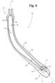
Fig. 6 is a cross-sectional plan view of the lower arm ofFig. 3 , showing a configuration of a hollow core; -
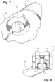
Fig. 7 is a perspective view of a first end of the lower arm ofFig. 6 , showing a first bore into the hollow core; and -
Fig. 8 is a perspective view of a second end of the lower arm ofFig. 6 , showing a second pore into the hollow core. - Reference will now be made to the drawings wherein like reference numerals identify similar structural features or aspects of the subject disclosure. For purposes of explanation and illustration, and not limitation, a partial view of an embodiment of a wiper apparatus in accordance with the disclosure is shown in
Fig. 1 and is designated generally byreference character 100. Other embodiments of systems in accordance with the disclosure, or aspects thereof, are provided inFigs. 2-8 , as will be described. The systems and methods described herein can be used to improve aerodynamics, weight, manufacturability, and overall performance of wiper arms and wiper systems such as for use on aircraft cockpit windshields. - The
wiper apparatus 100 includes awiper axis interface 102 mounting thewiper assembly 104 to a wiper drive 106 (labeled inFig. 2 ) of anaircraft 108. Alower wiper arm 110 extends from thewiper axis interface 102 to awiper mount 112, which is in the form of a clevis, that is connects thelower arm 110 to anupper arm 114. Abridge 116 is mounted to an end of theupper arm 114 opposite thewiper mount 112. Awiper blade 118 is operatively connected to thebridge 116 for wiping thecockpit windshield 120. Referring toFig. 2 , thewiper axis interface 102 is mounted to the wiper drive 106 so the wiper drive 106 can drive the lower wiper arm 110 (and therefore the entire wiper assembly 104) with reciprocating motion about a rotation axis A defined by thewiper axis interface 102. The reciprocating motion is in the direction of the double headedarrow 122 inFig. 2 . - With reference now to
Fig. 3 , afirst end 124 of thelower wiper arm 110 proximate thewiper axis interface 102 has a first airfoil profile, i.e. the cross-section at the location indicated inFig. 3 and shown inFig. 4 . Asecond end 126 of thelower wiper arm 110 proximate thewiper mount 112 has a second airfoil profile, i.e. the cross section at the location indicated inFig. 3 and shown inFig. 5 . Anintermediate portion 128 of thelower wiper arm 110 extends between the first andsecond ends Fig. 3 to the second airfoil profile shown inFig. 4 . Thelower wiper arm 110 defines a curve in theintermediate portion 128 so a first longitudinal axis L1 of the lower wiper arm defined by the first end is oblique relative to a second longitudinal axis of the lower arm defined at the second end, e.g. by an angle θ of about 30-degrees but those skilled in the art will readily appreciate that any suitable angle θ can be used without departing from the scope of this disclosure. - The aerodynamics of these airfoil profiles provide for reduced forces on the
lower wiper arm 110 in most positions of the reciprocating motion inFig. 1 , e.g. including for the airflow direction indicated by the large arrow inFig. 3. Figs. 4 and 5 show the chord lengths C and the maximum thicknesses T for the first and second airfoil profiles. The portion of thelower arm 110 that is most transverse to the air flow direction indicated inFig. 3 is the portion with the airfoil profile having the highest ratio C/T of chord length C to maximum chord thickness T, i.e. is the most streamlined portion to flow transverse to the airfoil. The ratio of C/T changes smoothly along the length of theintermediate portion 128. The portion of thelower arm 110 that is least transverse to the air flow direction indicated inFig. 3 is the portion with the lowest ratio of C/T, i.e. the least streamlined portion to flow transverse to the airfoil. The first airfoil profile, shown inFig. 4 has a smaller maximum thickness T than that of the second airfoil profile shown inFig. 5 . The first airfoil profile shown inFig. 4 has a longer chord line C than that of the second airfoil profile shown inFig. 5 . - With reference now to
Fig. 6 , thelower wiper arm 110 can be hollow, in which case anouter wall 130 of thelower wiper arm 110 is defined about ahollow core 132 of thelower wiper arm 110. At thefirst end 124 of the lower wiper arm, theouter wall 130 has a first wall thickness W. At thesecond end 126 of thelower wiper arm 110, theouter wall 130 has a second wall thickness W different from the first wall thickness. Along theintermediate portion 128, theouter wall 130 has a transitioning wall thickness W that transitions from the first wall thickness W to the second wall thickness W. This does not imply that each local thickness along the length is locally uniform in thickness, e.g. in a hoop direction around theouter wall 130, but instead the thickness can also very in the hoop direction in addition to in the end to end length direction of thelower wiper arm 110. The transitioning wall thickness transitions smoothly, i.e. continuously, from the first wall thickness W to the second wall thickness W. Smooth transition for the wall thickness may not be required, e.g. provided all external surface transition is smoothly maintained. The first wall thickness W, i.e. proximate thefirst end 124, is thicker than the second wall thickness W, i.e. proximate thesecond end 126. This thickness profile of theouter wall 130 allows for reduced weight relative to solid lower arm designs, while still providing the material strength where needed. - The
hollow core 132 terminates at afirst bore 134 that opens into aconnector bore 136 of thewiper axis interface 102, wherein thefirst bore 134 extends along the first longitudinal axis L1, as shown inFig. 7 . Thehollow core 132 ofFig. 3 also terminates at asecond bore 136 opening into theclevis 138 of the wiper mount, and extends along the second longitudinal axis L2, as shown inFig. 8 . The first andsecond bores hollow core 132, labeled inFig. 3 , after building thelower arm 110 in an additive manufacturing process. However, in thewiper assembly 104 ofFig. 1 , thefirst bore 134 ofFig. 1 is covered by a pin 140 of the wiper drive 106, and thesecond bore 136 is covered by theupper arm 114 connecting in theclevis 138 labeled inFig. 8 . This prevents water, ice, sand, dust, bugs, or other contaminants entering thehollow core 132 during use in flight or the like. Thesebores hollow core 132 as shown inFig. 3 . Thehollow core 132 is not an open channel, but a hollow core completely surrounded by theouter wall 132 but for the first andsecond bores Figs. 7-8 . - Systems and methods as disclosed herein can provide various potential benefits including the following. The cross section of the lower arm can be optimized with an airfoil shape with much lower drag than traditional configurations. This lowers drag on the aircraft, e.g. for fuel economy, and reduces loading on the wiper apparatus as a whole, leading to longer system life. The lower wiper arm can be structurally optimized as the airfoil profile can be stiffer in the bending direction of the lower arm than in traditional configurations. The airfoil profile sizing can also be driven by structural need as the highest stressed areas near the wiper axis interface can have the highest cross-sectional area and wall thickness, and the airfoil area and wall thickness can be reduced closer to the wiper mount.
- The methods and systems of the present disclosure, as described above and shown in the drawings, provide for improved aerodynamics, weight, manufacturability, and overall performance of wiper arms and wiper systems such as for use on aircraft cockpit windshields. While the apparatus and methods of the subject disclosure have been shown and described with reference to preferred embodiments, those skilled in the art will readily appreciate that changes and/or modifications may be made thereto without departing from the scope of the subject disclosure.
Claims (15)
- A wiper apparatus comprising:a wiper axis interface (102) configured for mounting a wiper assembly (104) to a wiper drive (106); anda lower wiper arm (110) extending from the wiper axis interface to a wiper mount (112) that is configured to connect the lower arm to an upper arm (114), wherein a first end (124) of the lower wiper arm proximate the wiper axis interface has a first airfoil profile, wherein a second end (126) of the lower wiper arm proximate the wiper mount has a second airfoil profile, and wherein an intermediate portion (128) of the lower wiper arm extending between the first and second ends has a transitioning airfoil profile that transitions from the first airfoil profile to the second airfoil profile.
- The apparatus as recited in claim 1, wherein the first airfoil profile has a smaller maximum thickness than that of the second airfoil profile.
- The apparatus as recited in claim 1 or 2, wherein the first airfoil profile has a longer chord line than that of the second airfoil profile.
- The apparatus as recited in claim 1, 2 or 3, wherein the lower wiper arm (110) defines a curve so a first longitudinal axis (L1) of the lower wiper arm defined by the first end (124) is oblique relative to a second longitudinal axis (L2) of the lower arm defined at the second end (126).
- The apparatus as recited in any preceding claim, further comprising:the upper arm (114) connected to the wiper mount;a bridge (116) mounted to an end of the upper arm (114) opposite the wiper mount (112); anda wiper blade (118) operatively connected to the bridge for wiping a windshield.
- The apparatus as recited in any preceding claim, further comprising the wiper drive (106), wherein the wiper axis interface (102) is mounted to the wiper drive so the wiper drive can drive the lower wiper arm (110) with reciprocating motion about a rotation axis defined by the wiper axis interface.
- The apparatus as recited in any preceding claim, wherein an outer wall (130) of the lower wiper arm (110) is defined about a hollow core (132) of the lower wiper arm, wherein at the first end (124) of the lower wiper arm, the outer wall has a first wall thickness, wherein at the second end of the lower wiper arm, the outer wall has a second wall thickness different from the first wall thickness, and wherein along the intermediate portion (128), the outer wall has a transitioning wall thickness that transitions from the first wall thickness to the second wall thickness.
- The apparatus as recited in claim 7, wherein the hollow core (132) terminates at a first bore opening into a connector bore of the wiper axis interface, wherein the hollow core terminates at a second bore opening into a clevis (138) of the wiper mount (112).
- The apparatus as recited in any preceding claim, wherein the transitioning airfoil profile transitions smoothly from the first airfoil profile to the second airfoil profile.
- A wiper apparatus comprising:a wiper axis interface (102) configured for mounting a wiper assembly (104) to a wiper drive (106); anda lower wiper arm (110) extending from the wiper axis interface to a wiper mount (112) that is configured to connect the lower arm to an upper arm (114), wherein an outer wall (130) of the lower wiper arm is defined about a hollow core (132) of the lower wiper arm,wherein at a first end (124) of the lower wiper arm proximate the wiper axis interface, the outer wall has a first wall thickness, wherein at a second end (126) of the lower wiper arm proximate the wiper mount, the outer wall has a second wall thickness different from the first wall thickness, and wherein along an intermediate portion (128) of the lower wiper arm extending between the first and second ends, the outer wall has a transitioning wall thickness that transitions from the first wall thickness to the second wall thickness.
- The apparatus as recited in claim 10, wherein the first wall thickness is thicker than the second wall thickness, and wherein the transitioning wall thickness transitions smoothly from the first wall thickness to the second wall thickness.
- The apparatus as recited in claim 10 or 11, wherein the lower wiper arm (110) defines a curve so a first longitudinal axis (L1) of the lower wiper arm defined by the first end (124) is oblique relative to a second longitudinal axis (L2) of the lower arm defined at the second end (126).
- The apparatus as recited in claim 10, 11 or 12, further comprising:an upper arm (114) connected to the wiper mount (112);a bridge (116) mounted to an end of the upper arm opposite the wiper mount; anda wiper blade (118) operatively connected to the bridge for wiping a windshield.
- The apparatus as recited in any of claims 10 to 13, further comprising a wiper drive (106) of an aircraft, wherein the wiper axis interface (102) is mounted to the wiper drive so the wiper drive can drive the lower wiper arm (110) with reciprocating motion about a rotation axis defined by the wiper axis interface.
- The apparatus as recited in any of claims 10 to 14, wherein the hollow core (130) terminates at a first bore opening into a connector bore of the wiper axis interface (102), wherein the hollow core terminates at a second bore opening into a clevis (138) of the wiper mount (112).
Applications Claiming Priority (1)
| Application Number | Priority Date | Filing Date | Title |
|---|---|---|---|
| US18/137,617 US12252099B1 (en) | 2023-04-21 | 2023-04-21 | Variable airfoil profile hollow wiper arms |
Publications (2)
| Publication Number | Publication Date |
|---|---|
| EP4450339A2 true EP4450339A2 (en) | 2024-10-23 |
| EP4450339A3 EP4450339A3 (en) | 2024-12-11 |
Family
ID=90826283
Family Applications (1)
| Application Number | Title | Priority Date | Filing Date |
|---|---|---|---|
| EP24171673.7A Pending EP4450339A3 (en) | 2023-04-21 | 2024-04-22 | Variable airfoil profile hollow wiper arms |
Country Status (2)
| Country | Link |
|---|---|
| US (1) | US12252099B1 (en) |
| EP (1) | EP4450339A3 (en) |
Citations (1)
| Publication number | Priority date | Publication date | Assignee | Title |
|---|---|---|---|---|
| EP1452413A1 (en) * | 2003-02-28 | 2004-09-01 | Robert Bosch Gmbh | Wiping Device |
Family Cites Families (12)
| Publication number | Priority date | Publication date | Assignee | Title |
|---|---|---|---|---|
| EP0525850A1 (en) | 1991-07-29 | 1993-02-03 | General Motors Corporation | Moulded composite cantilever wiper arm |
| FR2716852B1 (en) | 1994-03-03 | 1996-04-19 | Valeo Systemes Dessuyage | Motor vehicle windshield wiper having an improved drive head. |
| DE19747857A1 (en) * | 1997-10-30 | 1999-05-06 | Bosch Gmbh Robert | Wiper arm for a wiper |
| JP3218211B2 (en) * | 1997-12-22 | 2001-10-15 | アスモ株式会社 | Wiper arm |
| DE19816213B4 (en) * | 1998-04-09 | 2005-02-24 | Knorr-Bremse Systeme für Schienenfahrzeuge GmbH | Wiper arm with wiper arm body comprising a curvature |
| FR2785248B1 (en) | 1998-10-28 | 2000-12-01 | Valeo Systemes Dessuyage | WINDSCREEN WIPER ARM CONFORMING TO AERODYNAMIC DEFLECTOR |
| US7272867B2 (en) * | 2002-10-28 | 2007-09-25 | Valeo Electrical Systems, Inc. | Windshield wiper system with drive arm |
| FR2868747B1 (en) | 2004-04-07 | 2008-06-20 | Valeo Systemes Dessuyage | FLAT-BLADE TYPE WIPER BLADE COMPRISING AERODYNAMIC DEFLECTOR |
| US20080289137A1 (en) | 2007-05-25 | 2008-11-27 | Michael Peter Ciaccio | Aerodynamic windshield wiper arm |
| FR2938807B1 (en) * | 2008-11-24 | 2012-04-06 | Airbus France | WINDSCREEN WIPERS FOR FRONT VEHICLE WINDOW. |
| EP2401181B1 (en) | 2009-02-27 | 2016-11-16 | Trico Products Corporation | Windshield wiper assembly having an optimized airfoil |
| DE102015221254A1 (en) | 2015-10-30 | 2017-05-04 | Ifa-Technologies Gmbh | Windscreen wiper device and vehicle with such a windshield wiper device |
-
2023
- 2023-04-21 US US18/137,617 patent/US12252099B1/en active Active
-
2024
- 2024-04-22 EP EP24171673.7A patent/EP4450339A3/en active Pending
Patent Citations (1)
| Publication number | Priority date | Publication date | Assignee | Title |
|---|---|---|---|---|
| EP1452413A1 (en) * | 2003-02-28 | 2004-09-01 | Robert Bosch Gmbh | Wiping Device |
Also Published As
| Publication number | Publication date |
|---|---|
| EP4450339A3 (en) | 2024-12-11 |
| US12252099B1 (en) | 2025-03-18 |
Similar Documents
| Publication | Publication Date | Title |
|---|---|---|
| US6796534B2 (en) | Method and apparatus for controlling airflow with a leading edge device having a flexible flow surface | |
| EP0781704B1 (en) | Vortex leading edge flap assembly for supersonic airplanes | |
| US6152405A (en) | Lift body having a variable camber | |
| US7946535B2 (en) | Highly efficient supersonic laminar flow wing | |
| US7246998B2 (en) | Mission replaceable rotor blade tip section | |
| RU2492111C2 (en) | End airfoils with recesses and appropriate systems and methods | |
| US6045096A (en) | Variable camber airfoil | |
| RU2698502C2 (en) | Bifurcated conjugated winglets | |
| US6415510B2 (en) | Method of fabricating leading edge nose structures of aerodynamic surfaces | |
| US4429844A (en) | Variable camber aircraft wing tip | |
| USRE44313E1 (en) | Airplane with unswept slotted cruise wing airfoil | |
| US5681014A (en) | Torsional twist airfoil control means | |
| EP0331603B1 (en) | Airfoiled blade | |
| CN101263277B (en) | Wind turbine blade | |
| EP0525850A1 (en) | Moulded composite cantilever wiper arm | |
| US20090218446A1 (en) | Aircraft structure with hinge rib assembly | |
| CA2505007A1 (en) | Proprotor blade with leading edge slot | |
| US20190061910A1 (en) | Edge morphing arrangement for an airfoil | |
| KR20180095460A (en) | A rib arrangement in a wing tip device | |
| US11254411B2 (en) | Airfoil-shaped body with a variable outer shape | |
| EP4450339A2 (en) | Variable airfoil profile hollow wiper arms | |
| CA1101817A (en) | Roll formed blade structure | |
| US7216429B2 (en) | Methods for replacement of a slotted tail rotor blade pitch horn | |
| US9233755B1 (en) | Highly efficient supersonic laminar flow wing structure | |
| EP4467402A1 (en) | Composite wiper arms |
Legal Events
| Date | Code | Title | Description |
|---|---|---|---|
| PUAI | Public reference made under article 153(3) epc to a published international application that has entered the european phase |
Free format text: ORIGINAL CODE: 0009012 |
|
| STAA | Information on the status of an ep patent application or granted ep patent |
Free format text: STATUS: THE APPLICATION HAS BEEN PUBLISHED |
|
| AK | Designated contracting states |
Kind code of ref document: A2 Designated state(s): AL AT BE BG CH CY CZ DE DK EE ES FI FR GB GR HR HU IE IS IT LI LT LU LV MC ME MK MT NL NO PL PT RO RS SE SI SK SM TR |
|
| PUAL | Search report despatched |
Free format text: ORIGINAL CODE: 0009013 |
|
| AK | Designated contracting states |
Kind code of ref document: A3 Designated state(s): AL AT BE BG CH CY CZ DE DK EE ES FI FR GB GR HR HU IE IS IT LI LT LU LV MC ME MK MT NL NO PL PT RO RS SE SI SK SM TR |
|
| RIC1 | Information provided on ipc code assigned before grant |
Ipc: B60S 1/32 20060101ALI20241107BHEP Ipc: B60S 1/34 20060101AFI20241107BHEP |
|
| STAA | Information on the status of an ep patent application or granted ep patent |
Free format text: STATUS: REQUEST FOR EXAMINATION WAS MADE |
|
| 17P | Request for examination filed |
Effective date: 20250602 |
|
| STAA | Information on the status of an ep patent application or granted ep patent |
Free format text: STATUS: EXAMINATION IS IN PROGRESS |
|
| 17Q | First examination report despatched |
Effective date: 20260312 |