EP4450320A1 - Bidirectional obc control circuit having charging and discharging functions, and control method therefor - Google Patents
Bidirectional obc control circuit having charging and discharging functions, and control method therefor Download PDFInfo
- Publication number
- EP4450320A1 EP4450320A1 EP23895869.8A EP23895869A EP4450320A1 EP 4450320 A1 EP4450320 A1 EP 4450320A1 EP 23895869 A EP23895869 A EP 23895869A EP 4450320 A1 EP4450320 A1 EP 4450320A1
- Authority
- EP
- European Patent Office
- Prior art keywords
- switch
- electric circuit
- vehicle electric
- mode
- obc
- Prior art date
- Legal status (The legal status is an assumption and is not a legal conclusion. Google has not performed a legal analysis and makes no representation as to the accuracy of the status listed.)
- Pending
Links
Images



Classifications
-
- B—PERFORMING OPERATIONS; TRANSPORTING
- B60—VEHICLES IN GENERAL
- B60L—PROPULSION OF ELECTRICALLY-PROPELLED VEHICLES; SUPPLYING ELECTRIC POWER FOR AUXILIARY EQUIPMENT OF ELECTRICALLY-PROPELLED VEHICLES; ELECTRODYNAMIC BRAKE SYSTEMS FOR VEHICLES IN GENERAL; MAGNETIC SUSPENSION OR LEVITATION FOR VEHICLES; MONITORING OPERATING VARIABLES OF ELECTRICALLY-PROPELLED VEHICLES; ELECTRIC SAFETY DEVICES FOR ELECTRICALLY-PROPELLED VEHICLES
- B60L55/00—Arrangements for supplying energy stored within a vehicle to a power network, i.e. vehicle-to-grid [V2G] arrangements
-
- B—PERFORMING OPERATIONS; TRANSPORTING
- B60—VEHICLES IN GENERAL
- B60L—PROPULSION OF ELECTRICALLY-PROPELLED VEHICLES; SUPPLYING ELECTRIC POWER FOR AUXILIARY EQUIPMENT OF ELECTRICALLY-PROPELLED VEHICLES; ELECTRODYNAMIC BRAKE SYSTEMS FOR VEHICLES IN GENERAL; MAGNETIC SUSPENSION OR LEVITATION FOR VEHICLES; MONITORING OPERATING VARIABLES OF ELECTRICALLY-PROPELLED VEHICLES; ELECTRIC SAFETY DEVICES FOR ELECTRICALLY-PROPELLED VEHICLES
- B60L53/00—Methods of charging batteries, specially adapted for electric vehicles; Charging stations or on-board charging equipment therefor; Exchange of energy storage elements in electric vehicles
- B60L53/20—Methods of charging batteries, specially adapted for electric vehicles; Charging stations or on-board charging equipment therefor; Exchange of energy storage elements in electric vehicles characterised by converters located in the vehicle
- B60L53/22—Constructional details or arrangements of charging converters specially adapted for charging electric vehicles
-
- B—PERFORMING OPERATIONS; TRANSPORTING
- B60—VEHICLES IN GENERAL
- B60L—PROPULSION OF ELECTRICALLY-PROPELLED VEHICLES; SUPPLYING ELECTRIC POWER FOR AUXILIARY EQUIPMENT OF ELECTRICALLY-PROPELLED VEHICLES; ELECTRODYNAMIC BRAKE SYSTEMS FOR VEHICLES IN GENERAL; MAGNETIC SUSPENSION OR LEVITATION FOR VEHICLES; MONITORING OPERATING VARIABLES OF ELECTRICALLY-PROPELLED VEHICLES; ELECTRIC SAFETY DEVICES FOR ELECTRICALLY-PROPELLED VEHICLES
- B60L53/00—Methods of charging batteries, specially adapted for electric vehicles; Charging stations or on-board charging equipment therefor; Exchange of energy storage elements in electric vehicles
- B60L53/20—Methods of charging batteries, specially adapted for electric vehicles; Charging stations or on-board charging equipment therefor; Exchange of energy storage elements in electric vehicles characterised by converters located in the vehicle
-
- B—PERFORMING OPERATIONS; TRANSPORTING
- B60—VEHICLES IN GENERAL
- B60L—PROPULSION OF ELECTRICALLY-PROPELLED VEHICLES; SUPPLYING ELECTRIC POWER FOR AUXILIARY EQUIPMENT OF ELECTRICALLY-PROPELLED VEHICLES; ELECTRODYNAMIC BRAKE SYSTEMS FOR VEHICLES IN GENERAL; MAGNETIC SUSPENSION OR LEVITATION FOR VEHICLES; MONITORING OPERATING VARIABLES OF ELECTRICALLY-PROPELLED VEHICLES; ELECTRIC SAFETY DEVICES FOR ELECTRICALLY-PROPELLED VEHICLES
- B60L1/00—Supplying electric power to auxiliary equipment of vehicles
-
- B—PERFORMING OPERATIONS; TRANSPORTING
- B60—VEHICLES IN GENERAL
- B60L—PROPULSION OF ELECTRICALLY-PROPELLED VEHICLES; SUPPLYING ELECTRIC POWER FOR AUXILIARY EQUIPMENT OF ELECTRICALLY-PROPELLED VEHICLES; ELECTRODYNAMIC BRAKE SYSTEMS FOR VEHICLES IN GENERAL; MAGNETIC SUSPENSION OR LEVITATION FOR VEHICLES; MONITORING OPERATING VARIABLES OF ELECTRICALLY-PROPELLED VEHICLES; ELECTRIC SAFETY DEVICES FOR ELECTRICALLY-PROPELLED VEHICLES
- B60L1/00—Supplying electric power to auxiliary equipment of vehicles
- B60L1/006—Supplying electric power to auxiliary equipment of vehicles to power outlets
-
- B—PERFORMING OPERATIONS; TRANSPORTING
- B60—VEHICLES IN GENERAL
- B60L—PROPULSION OF ELECTRICALLY-PROPELLED VEHICLES; SUPPLYING ELECTRIC POWER FOR AUXILIARY EQUIPMENT OF ELECTRICALLY-PROPELLED VEHICLES; ELECTRODYNAMIC BRAKE SYSTEMS FOR VEHICLES IN GENERAL; MAGNETIC SUSPENSION OR LEVITATION FOR VEHICLES; MONITORING OPERATING VARIABLES OF ELECTRICALLY-PROPELLED VEHICLES; ELECTRIC SAFETY DEVICES FOR ELECTRICALLY-PROPELLED VEHICLES
- B60L50/00—Electric propulsion with power supplied within the vehicle
- B60L50/50—Electric propulsion with power supplied within the vehicle using propulsion power supplied by batteries or fuel cells
- B60L50/53—Electric propulsion with power supplied within the vehicle using propulsion power supplied by batteries or fuel cells in combination with an external power supply, e.g. from overhead contact lines
-
- B—PERFORMING OPERATIONS; TRANSPORTING
- B60—VEHICLES IN GENERAL
- B60L—PROPULSION OF ELECTRICALLY-PROPELLED VEHICLES; SUPPLYING ELECTRIC POWER FOR AUXILIARY EQUIPMENT OF ELECTRICALLY-PROPELLED VEHICLES; ELECTRODYNAMIC BRAKE SYSTEMS FOR VEHICLES IN GENERAL; MAGNETIC SUSPENSION OR LEVITATION FOR VEHICLES; MONITORING OPERATING VARIABLES OF ELECTRICALLY-PROPELLED VEHICLES; ELECTRIC SAFETY DEVICES FOR ELECTRICALLY-PROPELLED VEHICLES
- B60L53/00—Methods of charging batteries, specially adapted for electric vehicles; Charging stations or on-board charging equipment therefor; Exchange of energy storage elements in electric vehicles
- B60L53/10—Methods of charging batteries, specially adapted for electric vehicles; Charging stations or on-board charging equipment therefor; Exchange of energy storage elements in electric vehicles characterised by the energy transfer between the charging station and the vehicle
- B60L53/14—Conductive energy transfer
-
- H—ELECTRICITY
- H02—GENERATION; CONVERSION OR DISTRIBUTION OF ELECTRIC POWER
- H02J—ELECTRIC POWER NETWORKS; CIRCUIT ARRANGEMENTS OR SYSTEMS FOR SUPPLYING OR DISTRIBUTING ELECTRIC POWER; SYSTEMS FOR STORING ELECTRIC ENERGY
- H02J3/00—Circuit arrangements for AC mains or AC distribution networks
- H02J3/28—Arrangements for balancing of the load in networks by storage of energy
- H02J3/32—Arrangements for balancing of the load in networks by storage of energy using batteries or super capacitors with converting means
- H02J3/322—Arrangements for balancing of the load in networks by storage of energy using batteries or super capacitors with converting means the battery being on-board an electric or hybrid vehicle, e.g. vehicle to grid arrangements [V2G], power aggregation, use of the battery for network load balancing, coordinated or cooperative battery charging
-
- H—ELECTRICITY
- H02—GENERATION; CONVERSION OR DISTRIBUTION OF ELECTRIC POWER
- H02J—ELECTRIC POWER NETWORKS; CIRCUIT ARRANGEMENTS OR SYSTEMS FOR SUPPLYING OR DISTRIBUTING ELECTRIC POWER; SYSTEMS FOR STORING ELECTRIC ENERGY
- H02J7/00—Circuit arrangements for charging or discharging batteries or for supplying loads from batteries
- H02J7/02—Circuit arrangements for charging or discharging batteries or for supplying loads from batteries for charging batteries from AC mains by converters
-
- H—ELECTRICITY
- H02—GENERATION; CONVERSION OR DISTRIBUTION OF ELECTRIC POWER
- H02J—ELECTRIC POWER NETWORKS; CIRCUIT ARRANGEMENTS OR SYSTEMS FOR SUPPLYING OR DISTRIBUTING ELECTRIC POWER; SYSTEMS FOR STORING ELECTRIC ENERGY
- H02J7/00—Circuit arrangements for charging or discharging batteries or for supplying loads from batteries
- H02J7/60—Circuit arrangements for charging or discharging batteries or for supplying loads from batteries including safety or protection arrangements
- H02J7/62—Circuit arrangements for charging or discharging batteries or for supplying loads from batteries including safety or protection arrangements against overcurrent
-
- H—ELECTRICITY
- H02—GENERATION; CONVERSION OR DISTRIBUTION OF ELECTRIC POWER
- H02J—ELECTRIC POWER NETWORKS; CIRCUIT ARRANGEMENTS OR SYSTEMS FOR SUPPLYING OR DISTRIBUTING ELECTRIC POWER; SYSTEMS FOR STORING ELECTRIC ENERGY
- H02J7/00—Circuit arrangements for charging or discharging batteries or for supplying loads from batteries
- H02J7/855—Circuit arrangements for charging or discharging batteries or for supplying loads from batteries with circuits adapted for supplying loads from the battery
-
- H—ELECTRICITY
- H02—GENERATION; CONVERSION OR DISTRIBUTION OF ELECTRIC POWER
- H02J—ELECTRIC POWER NETWORKS; CIRCUIT ARRANGEMENTS OR SYSTEMS FOR SUPPLYING OR DISTRIBUTING ELECTRIC POWER; SYSTEMS FOR STORING ELECTRIC ENERGY
- H02J7/00—Circuit arrangements for charging or discharging batteries or for supplying loads from batteries
- H02J7/865—Battery or charger load switching, e.g. concurrent charging and load supply
-
- B—PERFORMING OPERATIONS; TRANSPORTING
- B60—VEHICLES IN GENERAL
- B60L—PROPULSION OF ELECTRICALLY-PROPELLED VEHICLES; SUPPLYING ELECTRIC POWER FOR AUXILIARY EQUIPMENT OF ELECTRICALLY-PROPELLED VEHICLES; ELECTRODYNAMIC BRAKE SYSTEMS FOR VEHICLES IN GENERAL; MAGNETIC SUSPENSION OR LEVITATION FOR VEHICLES; MONITORING OPERATING VARIABLES OF ELECTRICALLY-PROPELLED VEHICLES; ELECTRIC SAFETY DEVICES FOR ELECTRICALLY-PROPELLED VEHICLES
- B60L2210/00—Converter types
- B60L2210/20—AC to AC converters
-
- B—PERFORMING OPERATIONS; TRANSPORTING
- B60—VEHICLES IN GENERAL
- B60L—PROPULSION OF ELECTRICALLY-PROPELLED VEHICLES; SUPPLYING ELECTRIC POWER FOR AUXILIARY EQUIPMENT OF ELECTRICALLY-PROPELLED VEHICLES; ELECTRODYNAMIC BRAKE SYSTEMS FOR VEHICLES IN GENERAL; MAGNETIC SUSPENSION OR LEVITATION FOR VEHICLES; MONITORING OPERATING VARIABLES OF ELECTRICALLY-PROPELLED VEHICLES; ELECTRIC SAFETY DEVICES FOR ELECTRICALLY-PROPELLED VEHICLES
- B60L2240/00—Control parameters of input or output; Target parameters
- B60L2240/40—Drive Train control parameters
- B60L2240/52—Drive Train control parameters related to converters
-
- B—PERFORMING OPERATIONS; TRANSPORTING
- B60—VEHICLES IN GENERAL
- B60L—PROPULSION OF ELECTRICALLY-PROPELLED VEHICLES; SUPPLYING ELECTRIC POWER FOR AUXILIARY EQUIPMENT OF ELECTRICALLY-PROPELLED VEHICLES; ELECTRODYNAMIC BRAKE SYSTEMS FOR VEHICLES IN GENERAL; MAGNETIC SUSPENSION OR LEVITATION FOR VEHICLES; MONITORING OPERATING VARIABLES OF ELECTRICALLY-PROPELLED VEHICLES; ELECTRIC SAFETY DEVICES FOR ELECTRICALLY-PROPELLED VEHICLES
- B60L2270/00—Problem solutions or means not otherwise provided for
- B60L2270/20—Inrush current reduction, i.e. avoiding high currents when connecting the battery
-
- H—ELECTRICITY
- H02—GENERATION; CONVERSION OR DISTRIBUTION OF ELECTRIC POWER
- H02J—ELECTRIC POWER NETWORKS; CIRCUIT ARRANGEMENTS OR SYSTEMS FOR SUPPLYING OR DISTRIBUTING ELECTRIC POWER; SYSTEMS FOR STORING ELECTRIC ENERGY
- H02J2105/00—Networks for supplying or distributing electric power characterised by their spatial reach or by the load
- H02J2105/30—Networks for supplying or distributing electric power characterised by their spatial reach or by the load the load networks being external to vehicles, i.e. exchanging power with vehicles
- H02J2105/33—Networks for supplying or distributing electric power characterised by their spatial reach or by the load the load networks being external to vehicles, i.e. exchanging power with vehicles exchanging power with road vehicles
- H02J2105/37—Networks for supplying or distributing electric power characterised by their spatial reach or by the load the load networks being external to vehicles, i.e. exchanging power with vehicles exchanging power with road vehicles exchanging power with electric vehicles [EV] or with hybrid electric vehicles [HEV]
-
- H—ELECTRICITY
- H02—GENERATION; CONVERSION OR DISTRIBUTION OF ELECTRIC POWER
- H02J—ELECTRIC POWER NETWORKS; CIRCUIT ARRANGEMENTS OR SYSTEMS FOR SUPPLYING OR DISTRIBUTING ELECTRIC POWER; SYSTEMS FOR STORING ELECTRIC ENERGY
- H02J2207/00—Details of circuit arrangements for charging or discharging batteries or supplying loads from batteries
- H02J2207/20—Charging or discharging characterised by the power electronics converter
-
- Y—GENERAL TAGGING OF NEW TECHNOLOGICAL DEVELOPMENTS; GENERAL TAGGING OF CROSS-SECTIONAL TECHNOLOGIES SPANNING OVER SEVERAL SECTIONS OF THE IPC; TECHNICAL SUBJECTS COVERED BY FORMER USPC CROSS-REFERENCE ART COLLECTIONS [XRACs] AND DIGESTS
- Y02—TECHNOLOGIES OR APPLICATIONS FOR MITIGATION OR ADAPTATION AGAINST CLIMATE CHANGE
- Y02T—CLIMATE CHANGE MITIGATION TECHNOLOGIES RELATED TO TRANSPORTATION
- Y02T10/00—Road transport of goods or passengers
- Y02T10/60—Other road transportation technologies with climate change mitigation effect
- Y02T10/70—Energy storage systems for electromobility, e.g. batteries
-
- Y—GENERAL TAGGING OF NEW TECHNOLOGICAL DEVELOPMENTS; GENERAL TAGGING OF CROSS-SECTIONAL TECHNOLOGIES SPANNING OVER SEVERAL SECTIONS OF THE IPC; TECHNICAL SUBJECTS COVERED BY FORMER USPC CROSS-REFERENCE ART COLLECTIONS [XRACs] AND DIGESTS
- Y02—TECHNOLOGIES OR APPLICATIONS FOR MITIGATION OR ADAPTATION AGAINST CLIMATE CHANGE
- Y02T—CLIMATE CHANGE MITIGATION TECHNOLOGIES RELATED TO TRANSPORTATION
- Y02T10/00—Road transport of goods or passengers
- Y02T10/60—Other road transportation technologies with climate change mitigation effect
- Y02T10/7072—Electromobility specific charging systems or methods for batteries, ultracapacitors, supercapacitors or double-layer capacitors
-
- Y—GENERAL TAGGING OF NEW TECHNOLOGICAL DEVELOPMENTS; GENERAL TAGGING OF CROSS-SECTIONAL TECHNOLOGIES SPANNING OVER SEVERAL SECTIONS OF THE IPC; TECHNICAL SUBJECTS COVERED BY FORMER USPC CROSS-REFERENCE ART COLLECTIONS [XRACs] AND DIGESTS
- Y02—TECHNOLOGIES OR APPLICATIONS FOR MITIGATION OR ADAPTATION AGAINST CLIMATE CHANGE
- Y02T—CLIMATE CHANGE MITIGATION TECHNOLOGIES RELATED TO TRANSPORTATION
- Y02T90/00—Enabling technologies or technologies with a potential or indirect contribution to GHG emissions mitigation
- Y02T90/10—Technologies relating to charging of electric vehicles
- Y02T90/14—Plug-in electric vehicles
Definitions
- the present invention relates to the technical field of on-board power-source circuits, in particular to an on-board OBC control circuit capable of bidirectionally charging and discharging and a control method thereof.
- a way of controlling relays to make contact or break contact enables an existing bidirectional on-board charger (OBC) to charge or discharge, and a Hall sensor is used to measure circuit currents.
- OBC on-board charger
- a Hall sensor is used to measure circuit currents.
- OBC bidirectional on-board charger
- alternating currents are connected to the OBC from a charging port to charge a battery
- a contravariant mode a vehicle battery outputs voltages to a vehicle charging port or an in-vehicle interface through a discharge device to supply power to relevant load equipment.
- the existing way of controlling OBC to charge or discharge through relays has the defect of resulting in a large number of relays and a large rated capacity.
- the present invention provides an on-board OBC control circuit capable of bidirectionally charging and discharging and a control method thereof.
- the switch module comprises a current-limiting resistor R, a first switch K1, a second switch K2 and a third switch K3, the current-limiting resistor R and the third switch K3 are connected with each other in series, then connected with the first switch K1 in parallel to form a unit, which is connected between a power line L1 of the out-vehicle electric circuit and a first end O1 of the bidirectional on-board OBC;
- the second switch K2 is connected between a power line L2 of the in-vehicle electric circuit and the first end O1 of the bidirectional on-board OBC;
- a zero line N1 of the out-vehicle electric circuit and a zero line N2 of the in-vehicle electric circuit are connected with each other in parallel, then connected to a second end O2 of the bidirectional on-board OBC.
- the first switch K1, the second switch K2, and the third switch K3 all adopt a single-pole single-throw relay.
- a rated capacity of the second switch K2 is 20% to 80% of a rated capacity of the first switch K1
- a rated capacity of the third switch K3 is 20% to 80% of a rated capacity of the first switch K1.
- the switch module comprises a current-limiting resistor R, a fourth switch K4 and a fifth switch K5, the fourth switch K4 is connected between a power line L1 of the out-vehicle electric circuit and a first end O1 of the bidirectional on-board OBC;
- the fifth switch K5 comprises a mobile break-contact head, a mobile make-contact head and a static contact head, the mobile break-contact head is connected in series with the current-limiting resistor R, then connected to the power line L1 of the out-vehicle electric circuit, the mobile make-contact head is connected to a power line L2 of the in-vehicle electric circuit, the static contact head is connected to the first end O1 of the bidirectional on-board OBC; a zero line N1 of the out-vehicle electric circuit and a zero line N2 of the in-vehicle electric circuit are connected with each other in parallel, then connected to a second end O2 of the bidirectional on-board OBC.
- the fourth switch K4 adopts a single-pole single-throw relay, but the fifth switch K5 adopts a single-pole double-throw relay.
- a rated capacity of the fifth switch K5 is 20% to 80% of a rated capacity of the fourth switch K4.
- the present invention further provides a method for controlling an on-board OBC control circuit capable of bidirectionally charging and discharging, comprising: using the on-board OBC control circuit capable of bidirectionally charging and discharging, which operates in a charge mode, in a contravariant mode and in the AC/AC mode; and controlling the control switch module to correspondingly act according to a selected mode, so as to form a route for electricity transmission; wherein in the charge mode, the out-vehicle electric circuit charges the bidirectional on-board OBC through the switch module; in the contravariant mode, the bidirectional on-board OBC discharges the out-vehicle electric circuit and/or the in-vehicle electric circuit through the switch module; in the AC/AC mode, the out-vehicle electric circuit connects the in-vehicle electric circuit through the switch module.
- the switch module comprises a current-limiting resistor R, a first switch K1, a second switch K2 and a third switch K3; in the charging mode, the first switch K1 makes contact, and the second switch K2 breaks contact; in the contravariant mode, the first switch K1 makes contact at the time of discharging to the out-vehicle electric circuit, the second switch K2 makes contact at the time of discharging to the in-vehicle electric circuit; the first switch K1 and the second switch K2 make contact at the time of concurrently discharging to the out-vehicle electric circuit and the in-vehicle electric circuit; in the AC/AC mode, the first switch K1 and the second switch K2 make contact.
- the switch module comprises a current-limiting resistor R, a fourth switch K4 and a fifth switch K5; in the charging mode, the fourth switch K4 makes contact; in the contravariant mode, the fourth switch K4 makes contact at the time of discharging to the out-vehicle electric circuit, a mobile make-contact head and a static contact head of the fifth switch K5 make contact at the time of discharging to the in-vehicle electric circuit; the fourth switch K4 makes contact, and the mobile make-contact head and static contact head of the fifth switch K5 make contact at the time of concurrently discharging to the out-vehicle electric circuit and the in-vehicle electric circuit; in the AC/AC mode, the fourth switch K4 makes contact, and the mobile make-contact head and static contact head of the fifth switch K5 make contact.
- the present invention discloses an on-board OBC control circuit capable of bidirectionally charging and discharging, including a switch module that connects an out-vehicle electric circuit and an in-vehicle electric circuit, and a bidirectional on-board OBC that operates in a charge mode, in a contravariant mode and in the AC/AC mode.
- the out-vehicle electric circuit charges the bidirectional on-board OBC through the switch module; in the contravariant mode, the bidirectional on-board OBC discharges the out-vehicle electric circuit and/or the in-vehicle electric circuit through the switch module; in the AC/AC mode, the out-vehicle electric circuit connects the in-vehicle electric circuit through the switch module.
- Fig. 1 has shown a circuit diagram of the first example of the present invention.
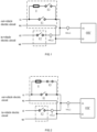
- the switch module includes a current-limiting resistor R, a first switch K1, a second switch K2 and a third switch K3, wherein the current-limiting resistor R and the third switch K3 are connected with each other in series, then connected with the first switch K1 in parallel to form a unit, which is connected between the power line L1 of the out-vehicle electric circuit and the first end O1 of the bidirectional on-board OBC; the second switch K2 is connected between the power line L2 of the in-vehicle electric circuit and the first end O1 of the bidirectional on-board OBC; the zero line N1 of the out-vehicle electric circuit and the zero line N2 of the in-vehicle electric circuit are connected with each other in parallel, then connected to the second end O2 of the bidirectional on-board OBC.
- the first switch K1, the second switch K2, and the third switch K3 all adopt a single-pole single-throw relay.
- the rated capacity of the second switch K2 is 20% to 80% of the rated capacity of the first switch K1
- the rated capacity of the third switch K3 is 20% to 80% of the rated capacity of the first switch K1.
- This design can not only decrease the number of relays, lower the rated capacity of relays, effectively lessen device volumes and reduce costs, but also meet the functional requirements of the circuit.
- the rated current that the rated capacity of relays allows to flow through relays and switch contacts is called touch-point capacity, also contact capacity.
- a current sensor is arranged in a main circuit of the bidirectional on-board OBC, and the controller in the bidirectional on-board OBC provides overcurrent protection for the circuit according to the current value measured by the current sensor.
- a first Hall sensor HALL1 is installed on a connection line of the first end O1
- a second Hall sensor HALL2 is installed on a connection line of the second switch K2.
- Fig.2 shows operation of soft power-up in the first example.
- the third switch K3 makes contact and the first switch K1 and the second switch K2 break contact, so that the alternating current is connected to the OBC after passing through the current limiting resistor R, so as to avoid damage to components caused by suddenly applying a large voltage on the OBC circuit.
- the first switch K1 make contact, the current limiting resistor R has a short circuit, and the alternating current directly is connected to the OBC through the first switch K1, and the circuit only operates in the charge mode at this time; its operation circuit is shown in Fig.3 .
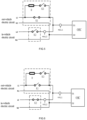
- the OBC When the OBC operates in a mode of not only charging but also discharging inside a vehicle, its operation circuit is shown in Fig.4 ; the first switch K1, the second switch K2 and the third switch K3 all make contact, a contact made on the first switch K1 connects a vehicle charging port to the OBC, a contact made on the second switch K2 connects an in-vehicle port to the OBC; the 220V alternating current is divided into two routes, one is connected to the OBC to realize the charging function, and the other is connected to the in-vehicle port to realize the discharging function inside the vehicle.
- the discharge mode in which the OBC operates may include a state of only discharging outside a vehicle, a state of only discharging inside a vehicle and a state of concurrently discharging inside and outside a vehicle; in the process of discharging, the discharge mode of the OBC is controlled by the first switch K1 and the second switch K2, and the third switch K3 is in a break-contact state to prevent the resistor from being burned out during discharging.
- the operation circuit of only discharging outside a vehicle is shown in Fig.5 , the first switch K1 makes contact, the second switch K2 and the third switch K3 break contact, and the 220V voltage is output to the charging port by the OBC, and the in-vehicle port is disconnected from the circuit.
- the operation circuit of only discharging inside a vehicle is shown in Fig.6 , the second switch K2 makes contact, the first switch K1 and the third switch K3 break contact, the OBC outputs the voltage to the in-vehicle port, and the first switch K1 and the third switch K3 are concurrently disconnected to ensure that the vehicle charging ports are not in live operation, improving safety performance.
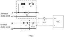
- the operation circuit of concurrently discharging inside and outside a vehicle is shown in Fig.7 , the first switch K1 and the second switch K2 make contact, the third switch K3 breaks contact, and the OBC outputs the voltage to the charging port and the in-vehicle port, so as to realize the function of concurrently discharging inside and outside a vehicle.
- the following table 1 indicates that the in-vehicle port and the out-of-vehicle port of the OBC are in a live state, Mark 1 represents a make-contact state of the relays and Mark 0 represents a break-contact of the relay; when the OBC is in the charge mode, the third switch K3 remains make-contact, and when it is in the contravariant mode, it remains break-contact; the OBC does not operate in the AC/AC mode, and all the vehicle ports are not in live state.
- the out-vehicle electric circuit In the charge mode, the out-vehicle electric circuit is always live; in the contravariant mode, the first end O1 and the second end O2 of the OBC are always live; in the AC/AC mode, the out-vehicle electric circuit is always live.
- the switch module includes a current-limiting resistor R, a fourth switch K4 and a fifth switch K5; wherein the fourth switch K4 is connected between the power line L1 of the out-vehicle electric circuit and the first end O1 of the bidirectional on-board OBC; the fifth switch K5 includes a mobile break-contact head (NC end), a mobile make-contact head (NO end) and a static contact head (Common end); when the coil of the fifth switch K5 is not electrified, the Common end is connected with the NC end by default to realize the function of charging or discharging outside a vehicle; after the coil has been electrified, the Common end is connected with the NO end to realize the function of discharging inside a vehicle.
- NC end mobile break-contact head
- NO end mobile make-contact head
- Common end static contact head
- the mobile break-contact head is connected in series with the current-limiting resistor R, then connected to the power line L1 of the out-vehicle electric circuit; the mobile make-contact head is connected to the power line L2 of the in-vehicle electric circuit; the static contact head is connected to the first end O1 of the bidirectional on-board OBC; the zero line N1 of the out-vehicle electric circuit and the zero line N2 of the in-vehicle electric circuit are connected with each other in parallel, then connected to the second end O2 of the bidirectional on-board OBC.
- the fourth switch K4 adopts a single-pole single-throw relay
- the fifth switch K5 adopts a single-pole double-throw relay
- the rated capacity of the fifth switch K5 is 20% to 80% of the rated capacity of the fourth switch K4. This design can not only decrease the number of relays, lower the rated capacity of relays, effectively lessen device volumes and reduce costs, but also meet the functional requirements of the circuit.
- a first Hall sensor HALL1 is installed on a connection line of the first end O1
- a second Hall sensor HALL2 is installed on a connection line of the static contact head.
- the Hall sensors detect current values in the circuit and transmit data to a controller, providing overcurrent protection for the circuit.
- the OBC When the OBC is in the charging mode, its operation circuit is shown in Fig.9 ; the Common end of the fifth switch K5 is connected with the NC end to connect the current-limiting resistor R to the OBC circuit; the alternating current flows into the OBC through the current-limiting resistor R for soft power-up; after soft power-up, the fourth switch K4 makes contact, thus the alternating current is connected to the OBC from the vehicle charging port, so as to charge a vehicle battery.
- the OBC When the OBC operates in a mode of not only charging but also discharging inside a vehicle, its operation circuit is shown in Fig. 11 ; the fourth switch K4 makes contact, and the Common end of the fifth switch K5 is switched to be connected with the NO end, so as to connect the OBC to the in-vehicle port, at this moment the alternating current is connected to the OBC through the fourth switch K4, and then is connected to the in-vehicle port through the fifth switch K5, realizing the function of discharging inside a vehicle.
- the OBC When the OBC is in the contravariant mode, it is achievable to control the discharge function by way of controlling the Common end of the fifth switch K5 to make and break contact with the NC end and the NO end.
- the OBC When the OBC only discharges outside a vehicle, its operation circuit diagram is consistent with Fig. 9 ; the fourth switch K4 firstly makes contact and then starts the contravariant mode of OBC, a contact made on the fourth switch K4 makes a short circuit between the current limiting resistor R and the fifth switch K5, and the OBC transmits a battery voltage to the vehicle charging port to realize the function of discharging outside a vehicle.
- the OBC only discharges inside a vehicle, its operation circuit diagram is shown in Fig.
- the fourth switch K4 breaks contact, the Common end of the fifth switch K5 is connected with the NO end, and the OBC transmits a battery voltage to the in-vehicle port, so as to realize the function of discharging inside a vehicle, at this moment the vehicle charging port is completely disconnected from the OBC, improving safety somewhat.
- the OBC concurrently discharges inside and outside a vehicle, its operation circuit diagram is shown in Fig.
- the fourth switch K4 makes contact, the Common end of the fifth switch K5 is connected with the NO end, the vehicle charging port and the in-vehicle port are concurrently connected with the OBC, thus a battery voltage is transmitted to the vehicle charging port and the in-vehicle port after starting of the OBC, realizing the function of concurrently discharging inside and outside a vehicle.
- the following table 2 indicates that the in-vehicle port and the out-of-vehicle port of the OBC are in a live state
- Mark 1 or Mark 0 represents a make-contact or break-contact state of the fourth switch K4
- NC represents a connection between the Common end of the fifth switch K5 and the NC end
- NO represents a connection between the Common end of the fifth switch K5 and the NO end
- in the charging mode the fourth switch K4 breaks contact, and the Common end of the fifth switch K5 is connected with the NC end, thus the out-vehicle port is live
- the fourth switch K4 breaks contact, and the connection of the Common end of the fifth switch K5 to the NC end is switched to a connection to the NO end after electrification, so as to realize the function of discharging inside a vehicle.
- the out-vehicle electric circuit In the charge mode, the out-vehicle electric circuit is always live; in the contravariant mode, the first end O1 and the second end O2 of the OBC are always live; in the AC/AC mode, the out-vehicle electric circuit is always live.
- the present invention further discloses a method for controlling an on-board OBC control circuit capable of bidirectionally charging and discharging, including using the above-mentioned on-board OBC control circuit capable of bidirectionally charging and discharging, which operates in a charge mode, in a contravariant mode and in the AC/AC mode, and controlling the control switch module to correspondingly act according to a selected mode, so as to form a route for electricity transmission; wherein in the charge mode, the out-vehicle electric circuit charges the bidirectional on-board OBC through the switch module; in the contravariant mode, the bidirectional on-board OBC discharges the out-vehicle electric circuit and/or the in-vehicle electric circuit through the switch module; in the AC/AC mode, the out-vehicle electric circuit connects the in-vehicle electric circuit through the switch module.
- the switch module includes a current-limiting resistor R, a first switch K1, a second switch K2 and a third switch K3; in the charging mode, the first switch K1 makes contact, and the second switch K2 breaks contact (as shown in Fig. 3 ); in the contravariant mode, the first switch K1 makes contact (as shown in Fig. 5 ) at the time of discharging to the out-vehicle electric circuit, the second switch K2 makes contact (as shown in Fig.
- the first switch K1 and the second switch K2 make contact at the time of concurrently discharging to the out-vehicle electric circuit and the in-vehicle electric circuit (as shown in Fig. 7 ); in the AC/AC mode, the first switch K1 and the second switch K2 make contact (as shown in Fig. 4 ).
- the switch module includes a current-limiting resistor R, a fourth switch K4 and a fifth switch K5; in the charging mode, the fourth switch K4 makes contact (as shown in Fig. 9 ), in the contravariant mode, the fourth switch K4 makes contact at the time of discharging to the out-vehicle electric circuit, the mobile make-contact head and the static contact head of the fifth switch K5 make contact (as shown in Fig. 10 ) at the time of discharging to the in-vehicle electric circuit; the fourth switch K4 makes contact, and the mobile make-contact head and static contact head of the fifth switch K5 make contact (as shown in Fig.
- the fourth switch K4 makes contact and the mobile make-contact head, and the static contact head of the fifth switch K5 make contact (as shown in Fig. 11 ).
Landscapes
- Engineering & Computer Science (AREA)
- Power Engineering (AREA)
- Transportation (AREA)
- Mechanical Engineering (AREA)
- Life Sciences & Earth Sciences (AREA)
- Sustainable Development (AREA)
- Sustainable Energy (AREA)
- Charge And Discharge Circuits For Batteries Or The Like (AREA)
- Electric Propulsion And Braking For Vehicles (AREA)
Abstract
Description
- The present invention relates to the technical field of on-board power-source circuits, in particular to an on-board OBC control circuit capable of bidirectionally charging and discharging and a control method thereof.
- A way of controlling relays to make contact or break contact enables an existing bidirectional on-board charger (OBC) to charge or discharge, and a Hall sensor is used to measure circuit currents. When the bidirectional OBC is in a charge mode, alternating currents are connected to the OBC from a charging port to charge a battery; when the OBC is in a contravariant mode, a vehicle battery outputs voltages to a vehicle charging port or an in-vehicle interface through a discharge device to supply power to relevant load equipment. However, the existing way of controlling OBC to charge or discharge through relays has the defect of resulting in a large number of relays and a large rated capacity.
- Therefore, how to design an on-board OBC control circuit capable of bidirectionally charging and discharging, which has a small number of relays and a relatively-small rated capacity, is a technical problem that needs to be solved urgently in this technical field.
- In order to solve the above-mentioned defect existing in the prior art, the present invention provides an on-board OBC control circuit capable of bidirectionally charging and discharging and a control method thereof.
- The technical solutions adopted in this present invention is to design an on-board OBC control circuit capable of bidirectionally charging and discharging, comprising a switch module that connects an out-vehicle electric circuit and an in-vehicle electric circuit, and a bidirectional on-board OBC that operates in a charge mode, in a contravariant mode and in the AC/AC mode; wherein in the charge mode, the out-vehicle electric circuit charges the bidirectional on-board OBC through the switch module; in the contravariant mode, the bidirectional on-board OBC discharges the out-vehicle electric circuit and/or the in-vehicle electric circuit through the switch module; in the AC/AC mode, the out-vehicle electric circuit connects the in-vehicle electric circuit through the switch module.
- In one technical solutions, the switch module comprises a current-limiting resistor R, a first switch K1, a second switch K2 and a third switch K3, the current-limiting resistor R and the third switch K3 are connected with each other in series, then connected with the first switch K1 in parallel to form a unit, which is connected between a power line L1 of the out-vehicle electric circuit and a first end O1 of the bidirectional on-board OBC; the second switch K2 is connected between a power line L2 of the in-vehicle electric circuit and the first end O1 of the bidirectional on-board OBC; a zero line N1 of the out-vehicle electric circuit and a zero line N2 of the in-vehicle electric circuit are connected with each other in parallel, then connected to a second end O2 of the bidirectional on-board OBC.
- The first switch K1, the second switch K2, and the third switch K3 all adopt a single-pole single-throw relay.
- A rated capacity of the second switch K2 is 20% to 80% of a rated capacity of the first switch K1, and a rated capacity of the third switch K3 is 20% to 80% of a rated capacity of the first switch K1.
- In another technical solutions, the switch module comprises a current-limiting resistor R, a fourth switch K4 and a fifth switch K5, the fourth switch K4 is connected between a power line L1 of the out-vehicle electric circuit and a first end O1 of the bidirectional on-board OBC; the fifth switch K5 comprises a mobile break-contact head, a mobile make-contact head and a static contact head, the mobile break-contact head is connected in series with the current-limiting resistor R, then connected to the power line L1 of the out-vehicle electric circuit, the mobile make-contact head is connected to a power line L2 of the in-vehicle electric circuit, the static contact head is connected to the first end O1 of the bidirectional on-board OBC; a zero line N1 of the out-vehicle electric circuit and a zero line N2 of the in-vehicle electric circuit are connected with each other in parallel, then connected to a second end O2 of the bidirectional on-board OBC.
- The fourth switch K4 adopts a single-pole single-throw relay, but the fifth switch K5 adopts a single-pole double-throw relay.
- A rated capacity of the fifth switch K5 is 20% to 80% of a rated capacity of the fourth switch K4.
- The present invention further provides a method for controlling an on-board OBC control circuit capable of bidirectionally charging and discharging, comprising: using the on-board OBC control circuit capable of bidirectionally charging and discharging, which operates in a charge mode, in a contravariant mode and in the AC/AC mode; and controlling the control switch module to correspondingly act according to a selected mode, so as to form a route for electricity transmission; wherein in the charge mode, the out-vehicle electric circuit charges the bidirectional on-board OBC through the switch module; in the contravariant mode, the bidirectional on-board OBC discharges the out-vehicle electric circuit and/or the in-vehicle electric circuit through the switch module; in the AC/AC mode, the out-vehicle electric circuit connects the in-vehicle electric circuit through the switch module.
- When the switch module comprises a current-limiting resistor R, a first switch K1, a second switch K2 and a third switch K3; in the charging mode, the first switch K1 makes contact, and the second switch K2 breaks contact; in the contravariant mode, the first switch K1 makes contact at the time of discharging to the out-vehicle electric circuit, the second switch K2 makes contact at the time of discharging to the in-vehicle electric circuit; the first switch K1 and the second switch K2 make contact at the time of concurrently discharging to the out-vehicle electric circuit and the in-vehicle electric circuit; in the AC/AC mode, the first switch K1 and the second switch K2 make contact.
- When the switch module comprises a current-limiting resistor R, a fourth switch K4 and a fifth switch K5; in the charging mode, the fourth switch K4 makes contact; in the contravariant mode, the fourth switch K4 makes contact at the time of discharging to the out-vehicle electric circuit, a mobile make-contact head and a static contact head of the fifth switch K5 make contact at the time of discharging to the in-vehicle electric circuit; the fourth switch K4 makes contact, and the mobile make-contact head and static contact head of the fifth switch K5 make contact at the time of concurrently discharging to the out-vehicle electric circuit and the in-vehicle electric circuit; in the AC/AC mode, the fourth switch K4 makes contact, and the mobile make-contact head and static contact head of the fifth switch K5 make contact.
- The technical solution provided by the present invention has the following beneficial effects.
- 1. When the OBC is in a charge mode, it is necessary to perform soft power-up, and the alternating current is connected to the OBC after passing through resistors, thus an impact is buffered on the OBC device; this way can effectively prevent the OBC circuit from getting impacted and causing damage at the moment of connecting the alternating current.
- 2. When the OBC is in an in-vehicle discharge mode, the relay connected to the out-vehicle L-wire is kept break-contact, and the charging port of the vehicle is completely disconnected from the circuit; this way can ensure that no electric shock will occur when a human body is in contact with the charging port, raising a level of security blankets.
- 3. The number of relays decreases, the rated capacity lowers, effectively lessening device volumes and reducing costs.
- We shall describe the present invention in detail in combination with the examples and drawings as follows, where:
-
Fig. 1 is a circuit diagram of the first example of the present invention. -
Fig.2 is a diagram showing soft power-up in the first example. -
Fig.3 is a diagram showing operation of charging in the first example. -
Fig.4 is a diagram showing operation of not only charging but also discharging inside a vehicle in the first example. -
Fig.5 is a diagram showing operation of only discharging outside a vehicle in the first example. -
Fig.6 is a diagram showing operation of only discharging inside a vehicle in the first example. -
Fig.7 is a diagram showing operation of concurrently discharging inside and outside a vehicle in the first example. -
Fig.8 is a circuit diagram of the second example of the present invention. -
Fig.9 is a diagram showing operation of charging in the second example. -
Fig. 10 is a diagram showing operation of discharging inside a vehicle in the second example. -
Fig. 11 is a diagram showing operation of not only charging but also discharging inside a vehicle in the second example. - In order to make the objectives, technical solutions, and advantages of the invention clearer, the invention is further described in detail with reference to the drawings and the embodiments as follows. It should be understood that the specific embodiments described here are only used to explain the invention, but not used to limit the invention.
- The present invention discloses an on-board OBC control circuit capable of bidirectionally charging and discharging, including a switch module that connects an out-vehicle electric circuit and an in-vehicle electric circuit, and a bidirectional on-board OBC that operates in a charge mode, in a contravariant mode and in the AC/AC mode. In the charge mode, the out-vehicle electric circuit charges the bidirectional on-board OBC through the switch module; in the contravariant mode, the bidirectional on-board OBC discharges the out-vehicle electric circuit and/or the in-vehicle electric circuit through the switch module; in the AC/AC mode, the out-vehicle electric circuit connects the in-vehicle electric circuit through the switch module.
-
Fig. 1 has shown a circuit diagram of the first example of the present invention. The switch module includes a current-limiting resistor R, a first switch K1, a second switch K2 and a third switch K3, wherein the current-limiting resistor R and the third switch K3 are connected with each other in series, then connected with the first switch K1 in parallel to form a unit, which is connected between the power line L1 of the out-vehicle electric circuit and the first end O1 of the bidirectional on-board OBC; the second switch K2 is connected between the power line L2 of the in-vehicle electric circuit and the first end O1 of the bidirectional on-board OBC; the zero line N1 of the out-vehicle electric circuit and the zero line N2 of the in-vehicle electric circuit are connected with each other in parallel, then connected to the second end O2 of the bidirectional on-board OBC. - In the first example, the first switch K1, the second switch K2, and the third switch K3 all adopt a single-pole single-throw relay.
- In the first example, the rated capacity of the second switch K2 is 20% to 80% of the rated capacity of the first switch K1, and the rated capacity of the third switch K3 is 20% to 80% of the rated capacity of the first switch K1. This design can not only decrease the number of relays, lower the rated capacity of relays, effectively lessen device volumes and reduce costs, but also meet the functional requirements of the circuit. The rated current that the rated capacity of relays allows to flow through relays and switch contacts is called touch-point capacity, also contact capacity.
- A current sensor is arranged in a main circuit of the bidirectional on-board OBC, and the controller in the bidirectional on-board OBC provides overcurrent protection for the circuit according to the current value measured by the current sensor. Referring to the example shown in
FIG. 1 ,
a first Hall sensor HALL1 is installed on a connection line of the first end O1, and a second Hall sensor HALL2 is installed on a connection line of the second switch K2. -
Fig.2 shows operation of soft power-up in the first example. When an OBC circuit starts, on soft power-up, the third switch K3 makes contact and the first switch K1 and the second switch K2 break contact, so that the alternating current is connected to the OBC after passing through the current limiting resistor R, so as to avoid damage to components caused by suddenly applying a large voltage on the OBC circuit. After ending soft power-up, the first switch K1 make contact, the current limiting resistor R has a short circuit, and the alternating current directly is connected to the OBC through the first switch K1, and the circuit only operates in the charge mode at this time; its operation circuit is shown inFig.3 . - When the OBC operates in a mode of not only charging but also discharging inside a vehicle, its operation circuit is shown in
Fig.4 ; the first switch K1, the second switch K2 and the third switch K3 all make contact, a contact made on the first switch K1 connects a vehicle charging port to the OBC, a contact made on the second switch K2 connects an in-vehicle port to the OBC; the 220V alternating current is divided into two routes, one is connected to the OBC to realize the charging function, and the other is connected to the in-vehicle port to realize the discharging function inside the vehicle. - The discharge mode in which the OBC operates may include a state of only discharging outside a vehicle, a state of only discharging inside a vehicle and a state of concurrently discharging inside and outside a vehicle; in the process of discharging, the discharge mode of the OBC is controlled by the first switch K1 and the second switch K2, and the third switch K3 is in a break-contact state to prevent the resistor from being burned out during discharging. The operation circuit of only discharging outside a vehicle is shown in
Fig.5 , the first switch K1 makes contact, the second switch K2 and the third switch K3 break contact, and the 220V voltage is output to the charging port by the OBC, and the in-vehicle port is disconnected from the circuit. The operation circuit of only discharging inside a vehicle is shown inFig.6 , the second switch K2 makes contact, the first switch K1 and the third switch K3 break contact, the OBC outputs the voltage to the in-vehicle port, and the first switch K1 and the third switch K3 are concurrently disconnected to ensure that the vehicle charging ports are not in live operation, improving safety performance. The operation circuit of concurrently discharging inside and outside a vehicle is shown inFig.7 , the first switch K1 and the second switch K2 make contact, the third switch K3 breaks contact, and the OBC outputs the voltage to the charging port and the in-vehicle port, so as to realize the function of concurrently discharging inside and outside a vehicle. - In the first example, the following table 1 indicates that the in-vehicle port and the out-of-vehicle port of the OBC are in a live state, Mark 1 represents a make-contact state of the relays and Mark 0 represents a break-contact of the relay; when the OBC is in the charge mode, the third switch K3 remains make-contact, and when it is in the contravariant mode, it remains break-contact; the OBC does not operate in the AC/AC mode, and all the vehicle ports are not in live state.

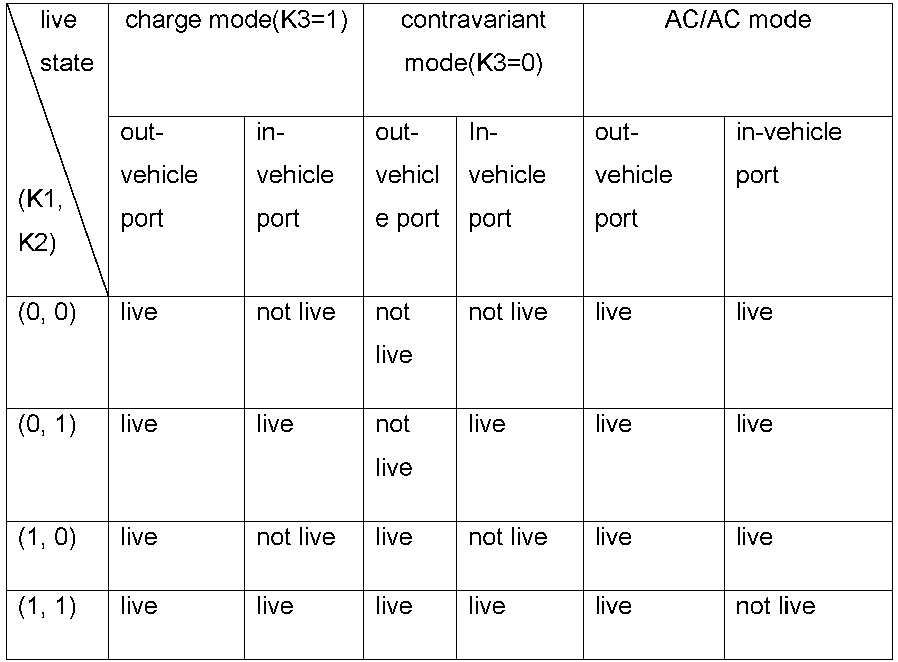
- Note: In the charge mode, the out-vehicle electric circuit is always live; in the contravariant mode, the first end O1 and the second end O2 of the OBC are always live; in the AC/AC mode, the out-vehicle electric circuit is always live.
- Referring to the second example shown in
Fig. 8 , the switch module includes a current-limiting resistor R, a fourth switch K4 and a fifth switch K5; wherein the fourth switch K4 is connected between the power line L1 of the out-vehicle electric circuit and the first end O1 of the bidirectional on-board OBC; the fifth switch K5 includes a mobile break-contact head (NC end), a mobile make-contact head (NO end) and a static contact head (Common end); when the coil of the fifth switch K5 is not electrified, the Common end is connected with the NC end by default to realize the function of charging or discharging outside a vehicle; after the coil has been electrified, the Common end is connected with the NO end to realize the function of discharging inside a vehicle. The mobile break-contact head is connected in series with the current-limiting resistor R, then connected to the power line L1 of the out-vehicle electric circuit; the mobile make-contact head is connected to the power line L2 of the in-vehicle electric circuit; the static contact head is connected to the first end O1 of the bidirectional on-board OBC; the zero line N1 of the out-vehicle electric circuit and the zero line N2 of the in-vehicle electric circuit are connected with each other in parallel, then connected to the second end O2 of the bidirectional on-board OBC. - In the second example, the fourth switch K4 adopts a single-pole single-throw relay, but the fifth switch K5 adopts a single-pole double-throw relay.
- In the second example, the rated capacity of the fifth switch K5 is 20% to 80% of the rated capacity of the fourth switch K4. This design can not only decrease the number of relays, lower the rated capacity of relays, effectively lessen device volumes and reduce costs, but also meet the functional requirements of the circuit.
- In the second example, a first Hall sensor HALL1 is installed on a connection line of the first end O1, and a second Hall sensor HALL2 is installed on a connection line of the static contact head. The Hall sensors detect current values in the circuit and transmit data to a controller, providing overcurrent protection for the circuit.
- When the OBC is in the charging mode, its operation circuit is shown in
Fig.9 ; the Common end of the fifth switch K5 is connected with the NC end to connect the current-limiting resistor R to the OBC circuit; the alternating current flows into the OBC through the current-limiting resistor R for soft power-up; after soft power-up, the fourth switch K4 makes contact, thus the alternating current is connected to the OBC from the vehicle charging port, so as to charge a vehicle battery. - When the OBC operates in a mode of not only charging but also discharging inside a vehicle, its operation circuit is shown in
Fig. 11 ; the fourth switch K4 makes contact, and the Common end of the fifth switch K5 is switched to be connected with the NO end, so as to connect the OBC to the in-vehicle port, at this moment the alternating current is connected to the OBC through the fourth switch K4, and then is connected to the in-vehicle port through the fifth switch K5, realizing the function of discharging inside a vehicle. - When the OBC is in the contravariant mode, it is achievable to control the discharge function by way of controlling the Common end of the fifth switch K5 to make and break contact with the NC end and the NO end. When the OBC only discharges outside a vehicle, its operation circuit diagram is consistent with
Fig. 9 ; the fourth switch K4 firstly makes contact and then starts the contravariant mode of OBC, a contact made on the fourth switch K4 makes a short circuit between the current limiting resistor R and the fifth switch K5, and the OBC transmits a battery voltage to the vehicle charging port to realize the function of discharging outside a vehicle. When the OBC only discharges inside a vehicle, its operation circuit diagram is shown inFig. 10 ; the fourth switch K4 breaks contact, the Common end of the fifth switch K5 is connected with the NO end, and the OBC transmits a battery voltage to the in-vehicle port, so as to realize the function of discharging inside a vehicle, at this moment the vehicle charging port is completely disconnected from the OBC, improving safety somewhat. When the OBC concurrently discharges inside and outside a vehicle, its operation circuit diagram is shown inFig. 11 ; the fourth switch K4 makes contact, the Common end of the fifth switch K5 is connected with the NO end, the vehicle charging port and the in-vehicle port are concurrently connected with the OBC, thus a battery voltage is transmitted to the vehicle charging port and the in-vehicle port after starting of the OBC, realizing the function of concurrently discharging inside and outside a vehicle. - In the second example, the following table 2 indicates that the in-vehicle port and the out-of-vehicle port of the OBC are in a live state,
Mark 1 or Mark 0 represents a make-contact or break-contact state of the fourth switch K4; NC represents a connection between the Common end of the fifth switch K5 and the NC end, and NO represents a connection between the Common end of the fifth switch K5 and the NO end; in the charging mode, the fourth switch K4 breaks contact, and the Common end of the fifth switch K5 is connected with the NC end, thus the out-vehicle port is live; in the contravariant mode, the fourth switch K4 breaks contact, and the connection of the Common end of the fifth switch K5 to the NC end is switched to a connection to the NO end after electrification, so as to realize the function of discharging inside a vehicle.

- Note: In the charge mode, the out-vehicle electric circuit is always live; in the contravariant mode, the first end O1 and the second end O2 of the OBC are always live; in the AC/AC mode, the out-vehicle electric circuit is always live.
- The present invention further discloses a method for controlling an on-board OBC control circuit capable of bidirectionally charging and discharging, including using the above-mentioned on-board OBC control circuit capable of bidirectionally charging and discharging, which operates in a charge mode, in a contravariant mode and in the AC/AC mode, and controlling the control switch module to correspondingly act according to a selected mode, so as to form a route for electricity transmission; wherein in the charge mode, the out-vehicle electric circuit charges the bidirectional on-board OBC through the switch module; in the contravariant mode, the bidirectional on-board OBC discharges the out-vehicle electric circuit and/or the in-vehicle electric circuit through the switch module; in the AC/AC mode, the out-vehicle electric circuit connects the in-vehicle electric circuit through the switch module.
- In the first example, the switch module includes a current-limiting resistor R, a first switch K1, a second switch K2 and a third switch K3; in the charging mode, the first switch K1 makes contact, and the second switch K2 breaks contact (as shown in
Fig. 3 ); in the contravariant mode, the first switch K1 makes contact (as shown inFig. 5 ) at the time of discharging to the out-vehicle electric circuit, the second switch K2 makes contact (as shown inFig. 6 ) at the time of discharging to the in-vehicle electric circuit; the first switch K1 and the second switch K2 make contact at the time of concurrently discharging to the out-vehicle electric circuit and the in-vehicle electric circuit (as shown inFig. 7 ); in the AC/AC mode, the first switch K1 and the second switch K2 make contact (as shown inFig. 4 ). - It should be pointed out that there will be a soft power-up phase (as shown in
Fig. 2 ) in the early stage of the charging mode, in which the first switch K1 firstly breaks contact, then the third switch K3 makes contact; the current-limiting resistor R is connected with the charging circuit in series, and the OBC is softly powered up under the action of limiting current. After ending the soft power-up phase, the first switch K1 makes contact and a short circuit is made between the current limiting resistor R connected in series and the third switch K3, thus the third switch K3 can either make contact or break contact. - In the second example, the switch module includes a current-limiting resistor R, a fourth switch K4 and a fifth switch K5; in the charging mode, the fourth switch K4 makes contact (as shown in
Fig. 9 ), in the contravariant mode, the fourth switch K4 makes contact at the time of discharging to the out-vehicle electric circuit, the mobile make-contact head and the static contact head of the fifth switch K5 make contact (as shown inFig. 10 ) at the time of discharging to the in-vehicle electric circuit; the fourth switch K4 makes contact, and the mobile make-contact head and static contact head of the fifth switch K5 make contact (as shown inFig. 11 ) at the time of concurrently discharging to the out-vehicle electric circuit and the in-vehicle electric circuit; in the AC/AC mode, the fourth switch K4 makes contact and the mobile make-contact head, and the static contact head of the fifth switch K5 make contact (as shown inFig. 11 ). - It should be pointed out that there will be a soft power-up phase (as shown in
Fig.8 ) in the early stage of the charging mode, in which the fourth switch K4 firstly breaks contact, then the mobile make-contact head and the static contact head of the fifth switch K5 make contact; the current-limiting resistor R is connected with the charging circuit in series, and the OBC is softly powered up under the action of limiting current. After ending the soft power-up phase, the fourth switch K4 makes contact and a short circuit is made between the current limiting resistor R connected in series and the mobile make-contact head and static contact head of the fifth switch K5, thus the mobile make-contact head and the static contact head of the fifth switch K5 can either make contact or break contact. - The above content only acts as a better embodiment of the present invention, not used to pose any limitation on the present invention, and any modifications, equivalent substitutions, improvements and the likes made within the essence and principle of the present invention will fall within the protection scope of the present invention.
Claims (10)
- An on-board OBC control circuit capable of bidirectionally charging and discharging, comprising a switch module that connects an out-vehicle electric circuit and an in-vehicle electric circuit, and a bidirectional on-board OBC that operates in a charge mode, in a contravariant mode and in the AC/AC mode;wherein in the charge mode, the out-vehicle electric circuit charges the bidirectional on-board OBC through the switch module;in the contravariant mode, the bidirectional on-board OBC discharges the out-vehicle electric circuit and/or the in-vehicle electric circuit through the switch module;in the AC/AC mode, the out-vehicle electric circuit connects the in-vehicle electric circuit through the switch module.
- The on-board OBC control circuit capable of bidirectionally charging and discharging according to claim 1, wherein the switch module comprises a current-limiting resistor R, a first switch K1, a second switch K2 and a third switch K3, the current-limiting resistor R and the third switch K3 are connected with each other in series, then connected with the first switch K1 in parallel to form a unit, which is connected between a power line L1 of the out-vehicle electric circuit and a first end O1 of the bidirectional on-board OBC; the second switch K2 is connected between a power line L2 of the in-vehicle electric circuit and the first end O1 of the bidirectional on-board OBC; a zero line N1 of the out-vehicle electric circuit and a zero line N2 of the in-vehicle electric circuit are connected with each other in parallel, then connected to a second end O2 of the bidirectional on-board OBC.
- The on-board OBC control circuit capable of bidirectionally charging and discharging according to claim 2, wherein the first switch K1, the second switch K2, and the third switch K3 all adopt a single-pole single-throw relay.
- The on-board OBC control circuit capable of bidirectionally charging and discharging according to claim 3, wherein a rated capacity of the second switch K2 is 20% to 80% of a rated capacity of the first switch K1, and a rated capacity of the third switch K3 is 20% to 80% of a rated capacity of the first switch K1.
- The on-board OBC control circuit capable of bidirectionally charging and discharging according to claim 1, wherein the switch module comprises a current-limiting resistor R, a fourth switch K4 and a fifth switch K5, the fourth switch K4 is connected between a power line L1 of the out-vehicle electric circuit and a first end O1 of the bidirectional on-board OBC; the fifth switch K5 comprises a mobile break-contact head, a mobile make-contact head and a static contact head, the mobile break-contact head is connected in series with the current-limiting resistor R, then connected to the power line L1 of the out-vehicle electric circuit, the mobile make-contact head is connected to a power line L2 of the in-vehicle electric circuit, the static contact head is connected to the first end O1 of the bidirectional on-board OBC; a zero line N1 of the out-vehicle electric circuit and a zero line N2 of the in-vehicle electric circuit are connected with each other in parallel, then connected to a second end O2 of the bidirectional on-board OBC.
- The on-board OBC control circuit capable of bidirectionally charging and discharging according to claim 5, wherein the fourth switch K4 adopts a single-pole single-throw relay, but the fifth switch K5 adopts a single-pole double-throw relay.
- The on-board OBC control circuit capable of bidirectionally charging and discharging according to claim 5, wherein a rated capacity of the fifth switch K5 is 20% to 80% of a rated capacity of the fourth switch K4.
- A method for controlling an on-board OBC control circuit capable of bidirectionally charging and discharging, comprising: using the on-board OBC control circuit capable of bidirectionally charging and discharging according to any one of claims 1-7, which operates in a charge mode, in a contravariant mode and in the AC/AC mode; and controlling the control switch module to correspondingly act according to a selected mode, so as to form a route for electricity transmission; wherein in the charge mode, the out-vehicle electric circuit charges the bidirectional on-board OBC through the switch module; in the contravariant mode, the bidirectional on-board OBC discharges the out-vehicle electric circuit and/or the in-vehicle electric circuit through the switch module; in the AC/AC mode, the out-vehicle electric circuit connects the in-vehicle electric circuit through the switch module.
- The method for controlling an on-board OBC control circuit capable of bidirectionally charging and discharging according to claim 8, wherein the switch module comprises a current-limiting resistor R, a first switch K1, a second switch K2 and a third switch K3;in the charging mode, the first switch K1 makes contact, and the second switch K2 breaks contact;in the contravariant mode, the first switch K1 makes contact at the time of discharging to the out-vehicle electric circuit, the second switch K2 makes contact at the time of discharging to the in-vehicle electric circuit; the first switch K1 and the second switch K2 make contact at the time of concurrently discharging to the out-vehicle electric circuit and the in-vehicle electric circuit;in the AC/AC mode, the first switch K1 and the second switch K2 make contact.
- The method for controlling an on-board OBC control circuit capable of bidirectionally charging and discharging according to claim 8, wherein the switch module comprises a current-limiting resistor R, a fourth switch K4 and a fifth switch K5;in the charging mode, the fourth switch K4 makes contact;in the contravariant mode, the fourth switch K4 makes contact at the time of discharging to the out-vehicle electric circuit, a mobile make-contact head and a static contact head of the fifth switch K5 make contact at the time of discharging to the in-vehicle electric circuit; the fourth switch K4 makes contact, and the mobile make-contact head and static contact head of the fifth switch K5 make contact at the time of concurrently discharging to the out-vehicle electric circuit and the in-vehicle electric circuit;in the AC/AC mode, the fourth switch K4 makes contact, and the mobile make-contact head and static contact head of the fifth switch K5 make contact.
Applications Claiming Priority (2)
| Application Number | Priority Date | Filing Date | Title |
|---|---|---|---|
| CN202211515983.3A CN116080435B (en) | 2022-11-29 | 2022-11-29 | Bidirectional On-Board Control Circuit with Charging and Discharging Function and its Control Method |
| PCT/CN2023/095581 WO2024113703A1 (en) | 2022-11-29 | 2023-05-22 | Bidirectional obc control circuit having charging and discharging functions, and control method therefor |
Publications (2)
| Publication Number | Publication Date |
|---|---|
| EP4450320A1 true EP4450320A1 (en) | 2024-10-23 |
| EP4450320A4 EP4450320A4 (en) | 2025-06-11 |
Family
ID=86207125
Family Applications (1)
| Application Number | Title | Priority Date | Filing Date |
|---|---|---|---|
| EP23895869.8A Pending EP4450320A4 (en) | 2022-11-29 | 2023-05-22 | Bidirectional OBC control circuit with charging and discharging functions and control methods therefor |
Country Status (4)
| Country | Link |
|---|---|
| US (1) | US20240391335A1 (en) |
| EP (1) | EP4450320A4 (en) |
| CN (1) | CN116080435B (en) |
| WO (1) | WO2024113703A1 (en) |
Families Citing this family (3)
| Publication number | Priority date | Publication date | Assignee | Title |
|---|---|---|---|---|
| CN116080435B (en) * | 2022-11-29 | 2026-03-06 | 深圳威迈斯新能源(集团)股份有限公司 | Bidirectional On-Board Control Circuit with Charging and Discharging Function and its Control Method |
| CN116766967A (en) * | 2023-06-27 | 2023-09-19 | 浙江吉利控股集团有限公司 | High-low voltage charge-discharge system, method and new energy automobile |
| CN116872763B (en) * | 2023-06-28 | 2026-04-21 | 重庆长安汽车股份有限公司 | A vehicle charging and discharging method, system and controller |
Family Cites Families (18)
| Publication number | Priority date | Publication date | Assignee | Title |
|---|---|---|---|---|
| US8897041B2 (en) * | 2012-01-31 | 2014-11-25 | Green Charge Networks Llc | Universal power conversion methods and systems |
| JP2013240191A (en) * | 2012-05-15 | 2013-11-28 | Toyota Motor Corp | Vehicle and control method for vehicle |
| JP2014143817A (en) * | 2013-01-23 | 2014-08-07 | Toyota Motor Corp | Vehicle power system |
| CN106160143B (en) * | 2016-07-22 | 2018-11-30 | 北京新能源汽车股份有限公司 | On-board charging devices for electric vehicles and electric vehicles |
| CN110014977B (en) * | 2017-08-15 | 2021-06-18 | 比亚迪股份有限公司 | Vehicle and vehicle-mounted charging system and control method thereof |
| CN107738589A (en) * | 2017-10-16 | 2018-02-27 | 安徽工程大学 | A kind of electric automobile drives discharge and recharge integrated apparatus |
| CN108202642A (en) * | 2018-03-22 | 2018-06-26 | 深圳市大地和电气股份有限公司 | Electric vehicle integrated driving system based on two-way inversion charge and discharge |
| CN108454440B (en) * | 2018-03-27 | 2021-04-13 | 浙江吉利控股集团有限公司 | A vehicle-to-vehicle charging device and method |
| IT201800006790A1 (en) * | 2018-06-28 | 2019-12-28 | AUXILIARY POWER SUPPLY SYSTEM FOR HIGH POWER LOADS IN A HYBRID / ELECTRIC VEHICLE | |
| CN109861357A (en) * | 2018-09-07 | 2019-06-07 | 台达电子工业股份有限公司 | Charging and discharging method and device |
| CN111384739B (en) * | 2018-12-29 | 2022-06-14 | 比亚迪股份有限公司 | Pre-charging circuit with in-vehicle discharge control function |
| CN110614930B (en) * | 2019-09-30 | 2022-11-18 | 重庆长安新能源汽车科技有限公司 | Charging and discharging method, system, controller and electric automobile |
| CN112912272A (en) * | 2020-07-17 | 2021-06-04 | 深圳欣锐科技股份有限公司 | Bidirectional vehicle-mounted charger, discharging method and electric vehicle |
| JP7294286B2 (en) * | 2020-09-18 | 2023-06-20 | トヨタ自動車株式会社 | charger and vehicle |
| KR102909364B1 (en) * | 2020-12-31 | 2026-01-20 | 현대자동차 주식회사 | Battery control method and battery system providing the same |
| CN115091955A (en) * | 2022-06-24 | 2022-09-23 | 东风汽车集团股份有限公司 | Charging and discharging system of electric automobile and control method thereof |
| CN218839210U (en) * | 2022-11-29 | 2023-04-11 | 深圳威迈斯新能源股份有限公司 | Bidirectional vehicle-mounted OBC control circuit with charging and discharging functions |
| CN116080435B (en) * | 2022-11-29 | 2026-03-06 | 深圳威迈斯新能源(集团)股份有限公司 | Bidirectional On-Board Control Circuit with Charging and Discharging Function and its Control Method |
-
2022
- 2022-11-29 CN CN202211515983.3A patent/CN116080435B/en active Active
-
2023
- 2023-05-22 EP EP23895869.8A patent/EP4450320A4/en active Pending
- 2023-05-22 WO PCT/CN2023/095581 patent/WO2024113703A1/en not_active Ceased
-
2024
- 2024-08-07 US US18/796,457 patent/US20240391335A1/en active Pending
Also Published As
| Publication number | Publication date |
|---|---|
| CN116080435B (en) | 2026-03-06 |
| US20240391335A1 (en) | 2024-11-28 |
| CN116080435A (en) | 2023-05-09 |
| EP4450320A4 (en) | 2025-06-11 |
| WO2024113703A1 (en) | 2024-06-06 |
Similar Documents
| Publication | Publication Date | Title |
|---|---|---|
| EP4450320A1 (en) | Bidirectional obc control circuit having charging and discharging functions, and control method therefor | |
| CN108819779B (en) | Charging system and electric automobile | |
| CN108909494B (en) | Charging system and electric automobile | |
| CN101318475A (en) | Simplified automatic discharge function for vehicles | |
| CN115091957A (en) | Device and method for diagnosing contact state of high-voltage upper and lower electric contactors and vehicle | |
| CN112098825B (en) | Detection circuit for fault of contactor coil | |
| EP3111541A1 (en) | Pre-charging switch arrangement, power supplying arrangement and method for connecting a load to a high direct-current voltage source | |
| CN109228870B (en) | Train and train power supply system and electric leakage detection and recovery device and method thereof | |
| CN109228873B (en) | Train and train power supply system and electric leakage detection and recovery device and method thereof | |
| CN112255539A (en) | Adhesion fault detection circuit of high-side contactor | |
| JP5939165B2 (en) | Rotating electrical machine control device | |
| KR20160081058A (en) | Method of checking state of pra | |
| CN110954798A (en) | Insulation detection starting judgment method and circuit for off-board charger | |
| CN210062685U (en) | High Voltage Discharge Devices and Vehicles | |
| CN112255540A (en) | A sticking fault detection circuit for low-side contactor | |
| CN112564194A (en) | Battery device, discharge system and discharge method | |
| CN114336854A (en) | Protection system and method for high-voltage direct-current charging of electric automobile | |
| KR102730413B1 (en) | Apparatus for diagnosing operation states of quick charge system in a electric vehcile | |
| CN112572230A (en) | Pre-charging and active discharging control circuit of electric automobile | |
| CN106936183A (en) | Power-supplying circuit, electric motor car charging guidance circuit and charging pile | |
| CN218839210U (en) | Bidirectional vehicle-mounted OBC control circuit with charging and discharging functions | |
| CN112636301B (en) | Bodywork plug-in operation system and construction machinery | |
| CN104836267A (en) | Charging/discharging control circuit | |
| CN113561780B (en) | High-voltage power distribution system, control method of high-voltage power distribution system and vehicle | |
| CN215772912U (en) | Direct current load soft start module, electrical equipment and system |
Legal Events
| Date | Code | Title | Description |
|---|---|---|---|
| STAA | Information on the status of an ep patent application or granted ep patent |
Free format text: STATUS: THE INTERNATIONAL PUBLICATION HAS BEEN MADE |
|
| PUAI | Public reference made under article 153(3) epc to a published international application that has entered the european phase |
Free format text: ORIGINAL CODE: 0009012 |
|
| STAA | Information on the status of an ep patent application or granted ep patent |
Free format text: STATUS: REQUEST FOR EXAMINATION WAS MADE |
|
| 17P | Request for examination filed |
Effective date: 20240716 |
|
| AK | Designated contracting states |
Kind code of ref document: A1 Designated state(s): AL AT BE BG CH CY CZ DE DK EE ES FI FR GB GR HR HU IE IS IT LI LT LU LV MC ME MK MT NL NO PL PT RO RS SE SI SK SM TR |
|
| A4 | Supplementary search report drawn up and despatched |
Effective date: 20250514 |
|
| RIC1 | Information provided on ipc code assigned before grant |
Ipc: H02J 7/00 20060101ALI20250508BHEP Ipc: H02J 3/32 20060101ALI20250508BHEP Ipc: B60L 55/00 20190101ALI20250508BHEP Ipc: B60L 50/53 20190101ALI20250508BHEP Ipc: B60L 53/20 20190101AFI20250508BHEP |
|
| STAA | Information on the status of an ep patent application or granted ep patent |
Free format text: STATUS: EXAMINATION IS IN PROGRESS |
|
| 17Q | First examination report despatched |
Effective date: 20251218 |
|
| DAV | Request for validation of the european patent (deleted) | ||
| DAX | Request for extension of the european patent (deleted) |