EP4450304A1 - Suspension device - Google Patents
Suspension device Download PDFInfo
- Publication number
- EP4450304A1 EP4450304A1 EP22907232.7A EP22907232A EP4450304A1 EP 4450304 A1 EP4450304 A1 EP 4450304A1 EP 22907232 A EP22907232 A EP 22907232A EP 4450304 A1 EP4450304 A1 EP 4450304A1
- Authority
- EP
- European Patent Office
- Prior art keywords
- end portion
- vehicle body
- torsion bar
- right direction
- rear direction
- Prior art date
- Legal status (The legal status is an assumption and is not a legal conclusion. Google has not performed a legal analysis and makes no representation as to the accuracy of the status listed.)
- Pending
Links
- 239000000725 suspension Substances 0.000 title claims abstract description 19
- 230000002093 peripheral effect Effects 0.000 claims description 13
- 230000008878 coupling Effects 0.000 description 8
- 238000010168 coupling process Methods 0.000 description 8
- 238000005859 coupling reaction Methods 0.000 description 8
- 239000011347 resin Substances 0.000 description 4
- 229920005989 resin Polymers 0.000 description 4
- 238000005452 bending Methods 0.000 description 3
- 230000008602 contraction Effects 0.000 description 3
- 241001247986 Calotropis procera Species 0.000 description 2
- 230000006866 deterioration Effects 0.000 description 2
- 239000000835 fiber Substances 0.000 description 2
- 239000003365 glass fiber Substances 0.000 description 2
- 229920000049 Carbon (fiber) Polymers 0.000 description 1
- 239000004917 carbon fiber Substances 0.000 description 1
- 238000006073 displacement reaction Methods 0.000 description 1
- 230000000694 effects Effects 0.000 description 1
- 239000002184 metal Substances 0.000 description 1
- VNWKTOKETHGBQD-UHFFFAOYSA-N methane Chemical compound C VNWKTOKETHGBQD-UHFFFAOYSA-N 0.000 description 1
- 230000004048 modification Effects 0.000 description 1
- 238000012986 modification Methods 0.000 description 1
- 238000003466 welding Methods 0.000 description 1
Images
Classifications
-
- B—PERFORMING OPERATIONS; TRANSPORTING
- B60—VEHICLES IN GENERAL
- B60G—VEHICLE SUSPENSION ARRANGEMENTS
- B60G11/00—Resilient suspensions characterised by arrangement, location or kind of springs
- B60G11/02—Resilient suspensions characterised by arrangement, location or kind of springs having leaf springs only
- B60G11/04—Resilient suspensions characterised by arrangement, location or kind of springs having leaf springs only arranged substantially parallel to the longitudinal axis of the vehicle
-
- B—PERFORMING OPERATIONS; TRANSPORTING
- B60—VEHICLES IN GENERAL
- B60G—VEHICLE SUSPENSION ARRANGEMENTS
- B60G11/00—Resilient suspensions characterised by arrangement, location or kind of springs
- B60G11/32—Resilient suspensions characterised by arrangement, location or kind of springs having springs of different kinds
- B60G11/34—Resilient suspensions characterised by arrangement, location or kind of springs having springs of different kinds including leaf springs
- B60G11/44—Resilient suspensions characterised by arrangement, location or kind of springs having springs of different kinds including leaf springs and also torsion-bar springs
-
- B—PERFORMING OPERATIONS; TRANSPORTING
- B60—VEHICLES IN GENERAL
- B60G—VEHICLE SUSPENSION ARRANGEMENTS
- B60G9/00—Resilient suspensions of a rigid axle or axle housing for two or more wheels
-
- B—PERFORMING OPERATIONS; TRANSPORTING
- B60—VEHICLES IN GENERAL
- B60G—VEHICLE SUSPENSION ARRANGEMENTS
- B60G2202/00—Indexing codes relating to the type of spring, damper or actuator
- B60G2202/10—Type of spring
- B60G2202/11—Leaf spring
- B60G2202/112—Leaf spring longitudinally arranged
-
- B—PERFORMING OPERATIONS; TRANSPORTING
- B60—VEHICLES IN GENERAL
- B60G—VEHICLE SUSPENSION ARRANGEMENTS
- B60G2202/00—Indexing codes relating to the type of spring, damper or actuator
- B60G2202/10—Type of spring
- B60G2202/13—Torsion spring
- B60G2202/132—Torsion spring comprising a longitudinal torsion bar and/or tube
-
- B—PERFORMING OPERATIONS; TRANSPORTING
- B60—VEHICLES IN GENERAL
- B60G—VEHICLE SUSPENSION ARRANGEMENTS
- B60G2204/00—Indexing codes related to suspensions per se or to auxiliary parts
- B60G2204/10—Mounting of suspension elements
- B60G2204/12—Mounting of springs or dampers
- B60G2204/121—Mounting of leaf springs
Definitions
- the present invention relates to a suspension device.
- a suspension device including a pair of leaf springs which extend in a front-rear direction, are disposed to be spaced apart from each other in a left-right direction, are attached to a vehicle body, and support an axle, and a torsion bar which extends in the front-rear direction and has a rear end portion supported by the axle is known.
- a front end portion of the leaf spring is connected to the vehicle body to be rotatable around an axis extending in the left-right direction
- a rear end portion of the leaf spring is connected to the vehicle body to be swingable in the front-rear direction around an axis extending in the left-right direction
- a front end portion of the torsion bar is supported by the vehicle body via a rubber bush.
- Patent Document 1 Japanese Examined Utility Model Application, Second Publication No. S49-009291
- the front end portion of the torsion bar is supported by the vehicle body via the rubber bush. Therefore, when the vehicle body and the axle are moved relative to each other in the up-down direction while bending and deforming the leaf spring in the up-down direction, displacement of the front end portion of the torsion bar in the front-rear direction is suppressed, and the expansion and contraction deformation of the leaf spring in the front-rear direction is suppressed. As a result, there is a possibility that, when the vehicle body and the axle are moved relative to each other in the up-down direction, the leaf spring may not be deformed as designed, and the smooth relative movement of the vehicle body and the axle in the front-rear direction may be hindered, which may deteriorate the riding comfort.
- the present invention has been made in consideration of such circumstances, and an object thereof is to provide a suspension device capable of deforming a leaf spring as designed when a vehicle body and an axle are moved relative to each other in an up-down direction.
- a suspension device includes a pair of leaf springs which extend in a front-rear direction, are disposed to be spaced apart from each other in a left-right direction, are attached to a vehicle body, and are configured to support an axle, and a torsion bar which extends in the front-rear direction, and of which one of a front end portion and a rear end portion is supported by the axle in a state where movement in the front-rear direction and the left-right direction is restricted, in which one of a front end portion and a rear end portion of the leaf spring is connected to the vehicle body to be rotatable around an axis extending in the left-right direction, and the other of the front end portion and the rear end portion of the leaf spring is connected to the vehicle body to be swingable in the front-rear direction around an axis extending in the left-right direction, and the other of the front end portion and the rear end portion of the torsion bar is supported by the vehicle body to be movable in the front-rear
- One of the front end portion and the rear end portion of the torsion bar is supported by the axle in a state where movement in the front-rear direction X and the left-right direction Y is restricted, and the other of the front end portion and the rear end portion of the torsion bar is supported by the vehicle body to be movable in the front-rear direction in a state where movement in the left-right direction Y is restricted.
- the other of the front end portion and the rear end portion of the torsion bar can be moved in the front-rear direction with respect to the vehicle body by following the expansion and contraction deformation of the leaf spring in the front-rear direction, and it is possible to deform the leaf spring as designed.
- the vehicle body and the axle are moved relative to each other in the up-down direction, it is possible to relatively smoothly move the vehicle body and the axle in the front-rear direction, and it is possible to prevent the deterioration of the riding comfort.
- the suspension device may further include a support tube into which the other of the front end portion and the rear end portion of the torsion bar is fitted to be slidable in the front-rear direction, and the support tube may be connected to the vehicle body to be swingable in the front-rear direction around a rotation axis extending in the left-right direction.
- the support tube into which the other of the front end portion and the rear end portion of the torsion bar is fitted to be slidable in the front-rear direction is connected to the vehicle body to be swingable in the front-rear direction around the rotation axis extending in the left-right direction. Therefore, when the vehicle body and the axle are moved relative to each other in the up-down direction, it is possible to slide the other of the front end portion and the rear end portion of the torsion bar in the front-rear direction with respect to the support tube while allowing the support tube to swing in the front-rear direction around the rotation axis.
- a transverse cross-sectional shape of an outer peripheral surface of the torsion bar may be a polygon shape, or an oval shape or an elliptical shape elongated in the left-right direction.
- the transverse cross-sectional shape of the outer peripheral surface of the torsion bar is a polygon shape, or an oval shape or an elliptical shape elongated in the left-right direction. Therefore, the torsional rigidity of the torsion bar can be increased, and the roll rigidity and the lateral rigidity between the vehicle body and the axle can be improved. In addition, it is possible to easily restrict the rotational movement of the torsion bar with respect to the support tube around the central axis, and it is possible to reliably improve the roll rigidity.
- the leaf spring can be deformed as designed when the vehicle body and the axle are moved relative to each other in the up-down direction.
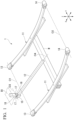
- FIG. 1 is a perspective view of a suspension device according to an embodiment.
- the suspension device 1 includes a pair of leaf springs 11 and a torsion bar 12.
- the suspension device 1 is used in a state where longitudinal directions of the leaf spring 11 and the torsion bar 12 match a front-rear direction X of a vehicle, in which the leaf springs 11 support an axle W extending in a left-right direction Y of the vehicle and the torsion bar 12 connects the axle W and a vehicle body B1 to each other in the front-rear direction X.
- the pair of leaf springs 11 are provided with an interval in the left-right direction Y.
- a central region of the leaf spring 11 in the front-rear direction X supports the axle W, and the leaf spring 11 is capable of being bent and deformed in an up-down direction Z.
- the leaf spring 11 supports the axle W from above the axle W.
- the leaf spring 11 may support the axle W from below the axle W.
- the leaf spring 11 is formed of, for example, a fiber-reinforced resin.
- fibers contained in the fiber-reinforced resin include a glass fiber, a carbon fiber, and the like.
- the leaf spring 11 is formed of fiber-reinforced resin containing glass fibers. The fibers are contained in the resin in a state of being substantially extended in the front-rear direction X.
- the leaf spring 11 may be formed of a metal or the like.
- the leaf spring 11 In a state where the leaf spring 11 is mounted onto the vehicle, the leaf spring 11 extends upward toward outer end portions from the central region in the front-rear direction X and is curved in a curved-surface shape protruding downward.
- the leaf spring 11 may extend straight in the front-rear direction X in a state where the leaf spring 11 is mounted onto the vehicle.
- the leaf spring 11 may extend downward toward the outer end portions from the central region in the front-rear direction X and may be curved in a curved-surface shape protruding upward.
- One of a front end portion and a rear end portion of the leaf spring 11 is connected to the vehicle body B1 to be rotatable around a first axis (axis) O1 extending in the left-right direction Y, and the other of the front end portion and the rear end portion of the leaf spring 11 is connected to the vehicle body B1 to be swingable in the front-rear direction X around an axis (not shown) extending in the left-right direction Y.
- the front end portion of the leaf spring 11 is attached to the vehicle body B1 via a first eyebolt portion 13, and the rear end portion of the leaf spring 11 is attached to the vehicle body B1 via a second eyebolt portion 14.
- the first eyebolt portion 13 and the second eyebolt portion 14 are formed separately from the leaf spring 11.
- the first eyebolt portion 13 and the second eyebolt portion 14 may be formed integrally with the leaf spring 11.
- the first eyebolt portion 13 is connected to the vehicle body B1 to be rotatable around the first axis O1 extending in the left-right direction Y.
- the second eyebolt portion 14 is connected to the vehicle body B1 via a coupling piece (not shown).
- the coupling piece extends in the up-down direction Z.
- An upper end portion of the coupling piece is connected to the vehicle body B1 to be rotatable around an axis (hereinafter, also referred to as a third axis) (not shown) extending in the left-right direction Y, and a lower end portion of the coupling piece is connected to the second eyebolt portion 14 to be rotatable around a second axis O2 extending in the left-right direction Y.
- the second eyebolt portion 14 is provided to be swingable in the front-rear direction X around the third axis positioned above the second axis O2.
- the second eyebolt portion 14 may be directly connected to the vehicle body B1 to be rotatable around the second axis 02, and the first eyebolt portion 13 may be connected to the vehicle body B1 via a coupling piece to be swingable in the front-rear direction X.
- One of a front end portion and a rear end portion of the torsion bar 12 is supported by the axle W in a state where movement in the front-rear direction X and the left-right direction Y is restricted, and the other of the front end portion and the rear end portion of the torsion bar 12 is supported by the vehicle body B1 to be movable in the front-rear direction X in a state where movement in the left-right direction Y is restricted.
- the torsion bar 12 is provided at a center portion of each of the vehicle body B1 and the axle W in the left-right direction Y.
- the torsion bar 12 may be provided at a position separated in the left-right direction Y from the center portion of each of the vehicle body B1 and the axle W in the left-right direction Y.
- the torsion bar 12 extends straight in the front-rear direction X when viewed in the up-down direction Z.
- the torsion bar 12 extends to the upper side as it goes forward.
- the torsion bar 12 may extend to the left side or the right side as it goes forward.
- the torsion bar 12 may extend to the lower side as it goes forward.
- the torsion bar 12 may be provided such that the position of the torsion bar 12 in the up-down direction Z is the same over the entire length in the front-rear direction X.
- the rear end portion of the torsion bar 12 is fixed to the axle W, and the front end portion of the torsion bar 12 is supported by the vehicle body B1.
- the rear end portion of the torsion bar 12 is fixed to the axle W by, for example, welding, a fastening member, or the like.
- the rear end portion of the torsion bar 12 may be supported by the axle W to be rotatable around an axis extending in the left-right direction Y.
- the front end portion of the torsion bar 12 may be supported by the axle W, and the rear end portion of the torsion bar 12 may be supported by the vehicle body B1.
- the suspension device 1 includes a support tube 15 into which the front end portion of the torsion bar 12 (the other of the front end portion and the rear end portion of the torsion bar 12) is fitted to be slidable in the front-rear direction X.
- the support tube 15 is connected to the vehicle body B1 to be swingable in the front-rear direction X around a rotation axis O3 extending in the left-right direction Y.
- the rotation axis O3 is positioned above the support tube 15.
- the support tube 15 and the torsion bar 12 are disposed coaxially with a common axis O4 extending in the front-rear direction X.
- Stopper portions may be provided on the support tube 15 and the torsion bar 12, respectively, the stopper portions that are engaged with each other to prevent the torsion bar 12 from escaping from the support tube 15 in the front-rear direction X.
- a supported protrusion 16 that protrudes upward is formed on the upper end portion of the support tube 15.
- a pair of support protrusions 17 that protrude downward and sandwich the supported protrusion 16 in the left-right direction Y are provided on the vehicle body B1. The upper portions of the pair of support protrusions 17 are connected to each other in the left-right direction Y.
- the support tube 15 swings with respect to the vehicle body B1 in the front-rear direction X around the rotation axis 03 by the rotation of the supported protrusion 16 around the rotation axis O3 with respect to the pair of support protrusions 17.
- the transverse cross-sectional shape of an outer peripheral surface of the torsion bar 12 is a polygon shape, or an oval shape or an elliptical shape elongated in the left-right direction Y.
- the transverse cross-sectional shape of the outer peripheral surface of the torsion bar 12 is a rectangular shape composed of four sides. Among these four sides, a pair of sides extend in the left-right direction Y, and the remaining pair of sides extend in the up-down direction Z.
- a transverse cross-sectional shape of the outer peripheral surface of the torsion bar 12 may be, for example, a polygon shape elongated in the left-right direction Y, or a circular shape.
- the front end portion of the torsion bar 12 is fitted into the support tube 15 to be slidable in the front-rear direction X in a state where the rotational movement in a circumferential direction of the common axis 04 is restricted.
- the transverse cross-sectional shape of the inner peripheral surface of the support tube 15 is the same as the transverse cross-sectional shape of the outer peripheral surface of the torsion bar 12.
- each of the transverse cross-sectional shapes of the inner peripheral surface of the support tube 15 and the outer peripheral surface of the torsion bar 12 is circular, uneven portions may be formed on the inner peripheral surface of the support tube 15 and the outer peripheral surface of the torsion bar 12, respectively, the uneven portions that are engaged with each other to restrict the relative rotation of the support tube 15 and the torsion bar 12 in the circumferential direction of the common axis O4.
- the leaf spring 11 When the vehicle body B1 and the axle W are moved relative to each other in the up-down direction Z, the leaf spring 11 is bent and deformed in the up-down direction Z and is expansion/contraction-deformed in the front-rear direction X, while the first eyebolt portion 13 rotates around the first axis O1 and the second eyebolt portion 14 swings in the front-rear direction X around the third axis positioned above the second axis 02.
- the rear end portion of the torsion bar 12 is supported by the axle W in a state where movement in the front-rear direction X and the left-right direction Y is restricted, and the front end portion of the torsion bar 12 is supported by the vehicle body B1 to be movable in the front-rear direction X in a state where movement in the left-right direction Y is restricted.
- the front end portion of the torsion bar 12 can be moved in the front-rear direction X with respect to the vehicle body B1 by following the expansion and contraction deformation of the leaf spring 11 in the front-rear direction X, and it is possible to deform the leaf spring 11 as designed.
- the vehicle body B1 and the axle W are moved relative to each other in the up-down direction Z, it is possible to relatively smoothly move the vehicle body B1 and the axle W in the front-rear direction X, and it is possible to prevent the deterioration of the riding comfort.
- the support tube 15 in which the front end portion of the torsion bar 12 is fitted to be slidable in the front-rear direction X is connected to the vehicle body B1 to be swingable in the front-rear direction X around the rotation axis O3 extending in the left-right direction Y. Therefore, when the vehicle body B1 and the axle W are moved relative to each other in the up-down direction Z, it is possible to slide the front end portion of the torsion bar 12 in the front-rear direction X with respect to the support tube 15 while allowing the support tube 15 to swing in the front-rear direction X around the rotation axis 03. As a result, the frictional force generated between the support tube 15 and the front end portion of the torsion bar 12 is suppressed, and it is possible to more smoothly move the vehicle body B1 and the axle W relative to each other in the front-rear direction X.
- the transverse cross-sectional shape of the outer peripheral surface of the torsion bar 12 is a polygon shape, or an oval shape or an elliptical shape elongated in the left-right direction Y. Therefore, the torsional rigidity of the torsion bar 12 can be increased, and the roll rigidity and the lateral rigidity between the vehicle body B1 and the axle W can be improved. In addition, it is possible to easily restrict the rotational movement of the torsion bar 12 with respect to the support tube 15 around the common axis 04, and it is possible to reliably improve the roll rigidity.
- the support tube 15 may be fixed to the vehicle body B1.
- the other of the front end portion and the rear end portion of the torsion bar 12 may be supported by the vehicle body B1 via a coupling piece extending in the up-down direction Z to be swingable in the front-rear direction X.
- the upper end portion of the coupling piece is connected to the vehicle body B1 to be rotatable around a rotation axis extending in the left-right direction Y
- the lower end portion of the coupling piece is connected to the other of the front end portion and the rear end portion of the torsion bar 12 to be rotatable around a rotation axis extending in the left-right direction Y.
- the leaf spring can be deformed as designed when the vehicle body and the axle are moved relative to each other in the up-down direction.
Landscapes
- Engineering & Computer Science (AREA)
- Mechanical Engineering (AREA)
- Vehicle Body Suspensions (AREA)
- Springs (AREA)
Abstract
Description
- The present invention relates to a suspension device.
- Priority is claimed on
Japanese Patent Application No. 2021-203026, filed December 15, 2021 - In the related art, for example, as shown in Patent Document 1 below, a suspension device including a pair of leaf springs which extend in a front-rear direction, are disposed to be spaced apart from each other in a left-right direction, are attached to a vehicle body, and support an axle, and a torsion bar which extends in the front-rear direction and has a rear end portion supported by the axle is known. In this suspension device, a front end portion of the leaf spring is connected to the vehicle body to be rotatable around an axis extending in the left-right direction, a rear end portion of the leaf spring is connected to the vehicle body to be swingable in the front-rear direction around an axis extending in the left-right direction, and a front end portion of the torsion bar is supported by the vehicle body via a rubber bush.
- [Patent Document 1]
Japanese Examined Utility Model Application, Second Publication No. S49-009291 - In the suspension device of the related art, the front end portion of the torsion bar is supported by the vehicle body via the rubber bush. Therefore, when the vehicle body and the axle are moved relative to each other in the up-down direction while bending and deforming the leaf spring in the up-down direction, displacement of the front end portion of the torsion bar in the front-rear direction is suppressed, and the expansion and contraction deformation of the leaf spring in the front-rear direction is suppressed. As a result, there is a possibility that, when the vehicle body and the axle are moved relative to each other in the up-down direction, the leaf spring may not be deformed as designed, and the smooth relative movement of the vehicle body and the axle in the front-rear direction may be hindered, which may deteriorate the riding comfort.
- The present invention has been made in consideration of such circumstances, and an object thereof is to provide a suspension device capable of deforming a leaf spring as designed when a vehicle body and an axle are moved relative to each other in an up-down direction.
- A suspension device according to an aspect of the present invention includes a pair of leaf springs which extend in a front-rear direction, are disposed to be spaced apart from each other in a left-right direction, are attached to a vehicle body, and are configured to support an axle, and a torsion bar which extends in the front-rear direction, and of which one of a front end portion and a rear end portion is supported by the axle in a state where movement in the front-rear direction and the left-right direction is restricted, in which one of a front end portion and a rear end portion of the leaf spring is connected to the vehicle body to be rotatable around an axis extending in the left-right direction, and the other of the front end portion and the rear end portion of the leaf spring is connected to the vehicle body to be swingable in the front-rear direction around an axis extending in the left-right direction, and the other of the front end portion and the rear end portion of the torsion bar is supported by the vehicle body to be movable in the front-rear direction in a state where movement in the left-right direction is restricted.
- One of the front end portion and the rear end portion of the torsion bar is supported by the axle in a state where movement in the front-rear direction X and the left-right direction Y is restricted, and the other of the front end portion and the rear end portion of the torsion bar is supported by the vehicle body to be movable in the front-rear direction in a state where movement in the left-right direction Y is restricted. Therefore, when the vehicle body and the axle are moved relative to each other in the up-down direction while bending and deforming the leaf spring in the up-down direction, the other of the front end portion and the rear end portion of the torsion bar can be moved in the front-rear direction with respect to the vehicle body by following the expansion and contraction deformation of the leaf spring in the front-rear direction, and it is possible to deform the leaf spring as designed. As a result, when the vehicle body and the axle are moved relative to each other in the up-down direction, it is possible to relatively smoothly move the vehicle body and the axle in the front-rear direction, and it is possible to prevent the deterioration of the riding comfort.
- The suspension device may further include a support tube into which the other of the front end portion and the rear end portion of the torsion bar is fitted to be slidable in the front-rear direction, and the support tube may be connected to the vehicle body to be swingable in the front-rear direction around a rotation axis extending in the left-right direction.
- The support tube into which the other of the front end portion and the rear end portion of the torsion bar is fitted to be slidable in the front-rear direction is connected to the vehicle body to be swingable in the front-rear direction around the rotation axis extending in the left-right direction. Therefore, when the vehicle body and the axle are moved relative to each other in the up-down direction, it is possible to slide the other of the front end portion and the rear end portion of the torsion bar in the front-rear direction with respect to the support tube while allowing the support tube to swing in the front-rear direction around the rotation axis. As a result, the frictional force generated between the support tube and the other of the front end portion and the rear end portion of the torsion bar is suppressed, and it is possible to more smoothly move the vehicle body and the axle relative to each other in the front-rear direction.
- A transverse cross-sectional shape of an outer peripheral surface of the torsion bar may be a polygon shape, or an oval shape or an elliptical shape elongated in the left-right direction.
- The transverse cross-sectional shape of the outer peripheral surface of the torsion bar is a polygon shape, or an oval shape or an elliptical shape elongated in the left-right direction. Therefore, the torsional rigidity of the torsion bar can be increased, and the roll rigidity and the lateral rigidity between the vehicle body and the axle can be improved. In addition, it is possible to easily restrict the rotational movement of the torsion bar with respect to the support tube around the central axis, and it is possible to reliably improve the roll rigidity.
- According to the present invention, the leaf spring can be deformed as designed when the vehicle body and the axle are moved relative to each other in the up-down direction.
-
FIG. 1 is a perspective view of a suspension device according to an embodiment. - Hereinafter, an embodiment of a suspension device will be described with reference to
FIG. 1 . - The suspension device 1 includes a pair of
leaf springs 11 and atorsion bar 12. The suspension device 1 is used in a state where longitudinal directions of theleaf spring 11 and thetorsion bar 12 match a front-rear direction X of a vehicle, in which theleaf springs 11 support an axle W extending in a left-right direction Y of the vehicle and thetorsion bar 12 connects the axle W and a vehicle body B1 to each other in the front-rear direction X. - The pair of
leaf springs 11 are provided with an interval in the left-right direction Y. A central region of theleaf spring 11 in the front-rear direction X supports the axle W, and theleaf spring 11 is capable of being bent and deformed in an up-down direction Z. Theleaf spring 11 supports the axle W from above the axle W. Theleaf spring 11 may support the axle W from below the axle W. - The
leaf spring 11 is formed of, for example, a fiber-reinforced resin. Examples of fibers contained in the fiber-reinforced resin include a glass fiber, a carbon fiber, and the like. In the shown example, theleaf spring 11 is formed of fiber-reinforced resin containing glass fibers. The fibers are contained in the resin in a state of being substantially extended in the front-rear direction X. - The
leaf spring 11 may be formed of a metal or the like. - In a state where the
leaf spring 11 is mounted onto the vehicle, theleaf spring 11 extends upward toward outer end portions from the central region in the front-rear direction X and is curved in a curved-surface shape protruding downward. - The
leaf spring 11 may extend straight in the front-rear direction X in a state where theleaf spring 11 is mounted onto the vehicle. Theleaf spring 11 may extend downward toward the outer end portions from the central region in the front-rear direction X and may be curved in a curved-surface shape protruding upward. - One of a front end portion and a rear end portion of the
leaf spring 11 is connected to the vehicle body B1 to be rotatable around a first axis (axis) O1 extending in the left-right direction Y, and the other of the front end portion and the rear end portion of theleaf spring 11 is connected to the vehicle body B1 to be swingable in the front-rear direction X around an axis (not shown) extending in the left-right direction Y. - In the shown example, the front end portion of the
leaf spring 11 is attached to the vehicle body B1 via afirst eyebolt portion 13, and the rear end portion of theleaf spring 11 is attached to the vehicle body B1 via asecond eyebolt portion 14. Thefirst eyebolt portion 13 and thesecond eyebolt portion 14 are formed separately from theleaf spring 11. Thefirst eyebolt portion 13 and thesecond eyebolt portion 14 may be formed integrally with theleaf spring 11. - The
first eyebolt portion 13 is connected to the vehicle body B1 to be rotatable around the first axis O1 extending in the left-right direction Y. - The
second eyebolt portion 14 is connected to the vehicle body B1 via a coupling piece (not shown). The coupling piece extends in the up-down direction Z. An upper end portion of the coupling piece is connected to the vehicle body B1 to be rotatable around an axis (hereinafter, also referred to as a third axis) (not shown) extending in the left-right direction Y, and a lower end portion of the coupling piece is connected to thesecond eyebolt portion 14 to be rotatable around a second axis O2 extending in the left-right direction Y. From the above, thesecond eyebolt portion 14 is provided to be swingable in the front-rear direction X around the third axis positioned above the second axis O2. - The
second eyebolt portion 14 may be directly connected to the vehicle body B1 to be rotatable around thesecond axis 02, and thefirst eyebolt portion 13 may be connected to the vehicle body B1 via a coupling piece to be swingable in the front-rear direction X. - One of a front end portion and a rear end portion of the
torsion bar 12 is supported by the axle W in a state where movement in the front-rear direction X and the left-right direction Y is restricted, and the other of the front end portion and the rear end portion of thetorsion bar 12 is supported by the vehicle body B1 to be movable in the front-rear direction X in a state where movement in the left-right direction Y is restricted. - The
torsion bar 12 is provided at a center portion of each of the vehicle body B1 and the axle W in the left-right direction Y. Thetorsion bar 12 may be provided at a position separated in the left-right direction Y from the center portion of each of the vehicle body B1 and the axle W in the left-right direction Y. - The
torsion bar 12 extends straight in the front-rear direction X when viewed in the up-down direction Z. Thetorsion bar 12 extends to the upper side as it goes forward. - The
torsion bar 12 may extend to the left side or the right side as it goes forward. Thetorsion bar 12 may extend to the lower side as it goes forward. Thetorsion bar 12 may be provided such that the position of thetorsion bar 12 in the up-down direction Z is the same over the entire length in the front-rear direction X. - In the shown example, the rear end portion of the
torsion bar 12 is fixed to the axle W, and the front end portion of thetorsion bar 12 is supported by the vehicle body B1. The rear end portion of thetorsion bar 12 is fixed to the axle W by, for example, welding, a fastening member, or the like. - The rear end portion of the
torsion bar 12 may be supported by the axle W to be rotatable around an axis extending in the left-right direction Y. In addition, the front end portion of thetorsion bar 12 may be supported by the axle W, and the rear end portion of thetorsion bar 12 may be supported by the vehicle body B1. - The suspension device 1 includes a
support tube 15 into which the front end portion of the torsion bar 12 (the other of the front end portion and the rear end portion of the torsion bar 12) is fitted to be slidable in the front-rear direction X. Thesupport tube 15 is connected to the vehicle body B1 to be swingable in the front-rear direction X around a rotation axis O3 extending in the left-right direction Y. The rotation axis O3 is positioned above thesupport tube 15. Thesupport tube 15 and thetorsion bar 12 are disposed coaxially with a common axis O4 extending in the front-rear direction X. - Stopper portions may be provided on the
support tube 15 and thetorsion bar 12, respectively, the stopper portions that are engaged with each other to prevent thetorsion bar 12 from escaping from thesupport tube 15 in the front-rear direction X. - A supported
protrusion 16 that protrudes upward is formed on the upper end portion of thesupport tube 15. A pair ofsupport protrusions 17 that protrude downward and sandwich the supportedprotrusion 16 in the left-right direction Y are provided on the vehicle body B1. The upper portions of the pair ofsupport protrusions 17 are connected to each other in the left-right direction Y. - A rotation shaft 18 that is disposed coaxially with the
rotation axis 03 integrally penetrates the supportedprotrusion 16 and the pair ofsupport protrusions 17 in the left-right direction Y. Thesupport tube 15 swings with respect to the vehicle body B1 in the front-rear direction X around therotation axis 03 by the rotation of the supportedprotrusion 16 around the rotation axis O3 with respect to the pair ofsupport protrusions 17. - The transverse cross-sectional shape of an outer peripheral surface of the
torsion bar 12 is a polygon shape, or an oval shape or an elliptical shape elongated in the left-right direction Y. In the shown example, the transverse cross-sectional shape of the outer peripheral surface of thetorsion bar 12 is a rectangular shape composed of four sides. Among these four sides, a pair of sides extend in the left-right direction Y, and the remaining pair of sides extend in the up-down direction Z. - A transverse cross-sectional shape of the outer peripheral surface of the
torsion bar 12 may be, for example, a polygon shape elongated in the left-right direction Y, or a circular shape. - The front end portion of the
torsion bar 12 is fitted into thesupport tube 15 to be slidable in the front-rear direction X in a state where the rotational movement in a circumferential direction of thecommon axis 04 is restricted. In the shown example, the transverse cross-sectional shape of the inner peripheral surface of thesupport tube 15 is the same as the transverse cross-sectional shape of the outer peripheral surface of thetorsion bar 12. - In a case where each of the transverse cross-sectional shapes of the inner peripheral surface of the
support tube 15 and the outer peripheral surface of thetorsion bar 12 is circular, uneven portions may be formed on the inner peripheral surface of thesupport tube 15 and the outer peripheral surface of thetorsion bar 12, respectively, the uneven portions that are engaged with each other to restrict the relative rotation of thesupport tube 15 and thetorsion bar 12 in the circumferential direction of the common axis O4. - When the vehicle body B1 and the axle W are moved relative to each other in the up-down direction Z, the
leaf spring 11 is bent and deformed in the up-down direction Z and is expansion/contraction-deformed in the front-rear direction X, while thefirst eyebolt portion 13 rotates around the first axis O1 and thesecond eyebolt portion 14 swings in the front-rear direction X around the third axis positioned above thesecond axis 02. - As described above, in the suspension device 1 according to the present embodiment, the rear end portion of the
torsion bar 12 is supported by the axle W in a state where movement in the front-rear direction X and the left-right direction Y is restricted, and the front end portion of thetorsion bar 12 is supported by the vehicle body B1 to be movable in the front-rear direction X in a state where movement in the left-right direction Y is restricted. - Therefore, when the vehicle body B1 and the axle W are moved relative to each other in the up-down direction Z while bending and deforming the
leaf spring 11 in the up-down direction Z, the front end portion of thetorsion bar 12 can be moved in the front-rear direction X with respect to the vehicle body B1 by following the expansion and contraction deformation of theleaf spring 11 in the front-rear direction X, and it is possible to deform theleaf spring 11 as designed. As a result, when the vehicle body B1 and the axle W are moved relative to each other in the up-down direction Z, it is possible to relatively smoothly move the vehicle body B1 and the axle W in the front-rear direction X, and it is possible to prevent the deterioration of the riding comfort. - The
support tube 15 in which the front end portion of thetorsion bar 12 is fitted to be slidable in the front-rear direction X is connected to the vehicle body B1 to be swingable in the front-rear direction X around the rotation axis O3 extending in the left-right direction Y. Therefore, when the vehicle body B1 and the axle W are moved relative to each other in the up-down direction Z, it is possible to slide the front end portion of thetorsion bar 12 in the front-rear direction X with respect to thesupport tube 15 while allowing thesupport tube 15 to swing in the front-rear direction X around therotation axis 03. As a result, the frictional force generated between thesupport tube 15 and the front end portion of thetorsion bar 12 is suppressed, and it is possible to more smoothly move the vehicle body B1 and the axle W relative to each other in the front-rear direction X. - The transverse cross-sectional shape of the outer peripheral surface of the
torsion bar 12 is a polygon shape, or an oval shape or an elliptical shape elongated in the left-right direction Y. Therefore, the torsional rigidity of thetorsion bar 12 can be increased, and the roll rigidity and the lateral rigidity between the vehicle body B1 and the axle W can be improved. In addition, it is possible to easily restrict the rotational movement of thetorsion bar 12 with respect to thesupport tube 15 around thecommon axis 04, and it is possible to reliably improve the roll rigidity. - The technical scope of the present invention is not limited to the above-described embodiments, and various modifications can be made within the scope not departing from the meaning of the present invention.
- For example, the
support tube 15 may be fixed to the vehicle body B1. - The other of the front end portion and the rear end portion of the
torsion bar 12 may be supported by the vehicle body B1 via a coupling piece extending in the up-down direction Z to be swingable in the front-rear direction X. In this configuration, the upper end portion of the coupling piece is connected to the vehicle body B1 to be rotatable around a rotation axis extending in the left-right direction Y, and the lower end portion of the coupling piece is connected to the other of the front end portion and the rear end portion of thetorsion bar 12 to be rotatable around a rotation axis extending in the left-right direction Y. - Furthermore, the components in the above-described embodiments can be appropriately replaced with well-known components within a range not departing from the meaning of the present invention, and the embodiments and modified examples described above may be appropriately combined.
- According to the present invention, the leaf spring can be deformed as designed when the vehicle body and the axle are moved relative to each other in the up-down direction.
-
- 1 Suspension device
- 11 Leaf spring
- 12 Torsion bar
- 15 Support tube
- B1 Vehicle body
- O1 First axis (axis)
- O3 Rotation axis
- W Axle
- X Front-rear direction
- Y Left-right direction
- Z Up-down direction
Claims (3)
- A suspension device comprising:a pair of leaf springs which extend in a front-rear direction, are disposed to be spaced apart from each other in a left-right direction, are attached to a vehicle body, and are configured to support an axle; anda torsion bar which extends in the front-rear direction, and of which one of a front end portion and a rear end portion is supported by the axle in a state where movement in the front-rear direction and the left-right direction is restricted,wherein one of a front end portion and a rear end portion of the leaf spring is connected to the vehicle body to be rotatable around an axis extending in the left-right direction, and the other of the front end portion and the rear end portion of the leaf spring is connected to the vehicle body to be swingable in the front-rear direction around an axis extending in the left-right direction, andthe other of the front end portion and the rear end portion of the torsion bar is supported by the vehicle body to be movable in the front-rear direction in a state where movement in the left-right direction is restricted.
- The suspension device according to Claim 1, further comprising:a support tube into which the other of the front end portion and the rear end portion of the torsion bar is fitted to be slidable in the front-rear direction,wherein the support tube is connected to the vehicle body to be swingable in the front-rear direction around a rotation axis extending in the left-right direction.
- The suspension device according to Claim 1 or 2, wherein a transverse cross-sectional shape of an outer peripheral surface of the torsion bar is a polygon shape, or an oval shape or an elliptical shape elongated in the left-right direction.
Applications Claiming Priority (2)
| Application Number | Priority Date | Filing Date | Title |
|---|---|---|---|
| JP2021203026A JP7692817B2 (en) | 2021-12-15 | 2021-12-15 | suspension system |
| PCT/JP2022/044407 WO2023112704A1 (en) | 2021-12-15 | 2022-12-01 | Suspension device |
Publications (2)
| Publication Number | Publication Date |
|---|---|
| EP4450304A1 true EP4450304A1 (en) | 2024-10-23 |
| EP4450304A4 EP4450304A4 (en) | 2025-04-09 |
Family
ID=86774266
Family Applications (1)
| Application Number | Title | Priority Date | Filing Date |
|---|---|---|---|
| EP22907232.7A Pending EP4450304A4 (en) | 2021-12-15 | 2022-12-01 | SUSPENSION DEVICE |
Country Status (6)
| Country | Link |
|---|---|
| US (1) | US20240326535A1 (en) |
| EP (1) | EP4450304A4 (en) |
| JP (1) | JP7692817B2 (en) |
| CN (1) | CN118382544A (en) |
| MX (1) | MX2024006842A (en) |
| WO (1) | WO2023112704A1 (en) |
Family Cites Families (7)
| Publication number | Priority date | Publication date | Assignee | Title |
|---|---|---|---|---|
| JPS499291U (en) | 1972-04-25 | 1974-01-26 | ||
| JPS57159505U (en) * | 1981-03-30 | 1982-10-06 | ||
| JPH03112707A (en) * | 1989-09-27 | 1991-05-14 | Mazda Motor Corp | Suspension device for vehicle |
| JPH03203026A (en) | 1989-12-28 | 1991-09-04 | Tokin Corp | Manufacture of magnetic recording medium |
| JP2539356Y2 (en) * | 1990-10-24 | 1997-06-25 | トヨタ自動車株式会社 | Suspension link device with anisotropic spring constant |
| JP3046569U (en) | 1997-08-26 | 1998-03-10 | 三菱製鋼株式会社 | Stabilizer for vehicle combined with torque rod |
| KR20060038220A (en) * | 2004-10-29 | 2006-05-03 | 기아자동차주식회사 | Lateral link apparatus of a suspension |
-
2021
- 2021-12-15 JP JP2021203026A patent/JP7692817B2/en active Active
-
2022
- 2022-12-01 WO PCT/JP2022/044407 patent/WO2023112704A1/en not_active Ceased
- 2022-12-01 CN CN202280082299.2A patent/CN118382544A/en active Pending
- 2022-12-01 MX MX2024006842A patent/MX2024006842A/en unknown
- 2022-12-01 EP EP22907232.7A patent/EP4450304A4/en active Pending
-
2024
- 2024-06-11 US US18/739,486 patent/US20240326535A1/en active Pending
Also Published As
| Publication number | Publication date |
|---|---|
| JP2023088362A (en) | 2023-06-27 |
| MX2024006842A (en) | 2024-06-19 |
| EP4450304A4 (en) | 2025-04-09 |
| JP7692817B2 (en) | 2025-06-16 |
| WO2023112704A1 (en) | 2023-06-22 |
| CN118382544A (en) | 2024-07-23 |
| US20240326535A1 (en) | 2024-10-03 |
Similar Documents
| Publication | Publication Date | Title |
|---|---|---|
| US7896372B2 (en) | Suspension device | |
| US8777247B2 (en) | Wheel suspension device for a motor vehicle | |
| US7387307B2 (en) | Suspension system | |
| JP4692578B2 (en) | Vehicle suspension arm | |
| EP2062754A2 (en) | Lower spring seat mounting structure for vehicle suspension | |
| US20190092113A1 (en) | Multi-link suspension for a motor vehicle | |
| EP2540534A1 (en) | Suspension structure, bush structure and suspension characteristic adjusting method | |
| KR20080109873A (en) | Car Seat Back Frame | |
| EP2524824B1 (en) | Suspension structure and method of making suspension link | |
| JPH10236123A (en) | Torsion beam suspension | |
| US9931902B2 (en) | Stabilizer bushing and stabilizer-bar mounting device | |
| KR20020030019A (en) | Rear suspension | |
| CN111448084A (en) | Suspension device and lower arm | |
| EP1707409B1 (en) | Torsion beam type rear suspension | |
| EP2794307B1 (en) | Front leaf spring | |
| JP2008249081A (en) | Bush and suspension device | |
| RU2668510C2 (en) | Torsion beam suspension | |
| US20240326535A1 (en) | Suspension device | |
| JP5707124B2 (en) | Suspension frame structure | |
| JP4403860B2 (en) | Vehicle suspension system | |
| JP6973744B2 (en) | Torsion beam | |
| CN210026947U (en) | Suspension system and vehicle | |
| JPH06270642A (en) | Stabilizer for car | |
| JP2007062567A (en) | Automotive suspension | |
| JP2007290422A (en) | Independent suspension system |
Legal Events
| Date | Code | Title | Description |
|---|---|---|---|
| STAA | Information on the status of an ep patent application or granted ep patent |
Free format text: STATUS: THE INTERNATIONAL PUBLICATION HAS BEEN MADE |
|
| PUAI | Public reference made under article 153(3) epc to a published international application that has entered the european phase |
Free format text: ORIGINAL CODE: 0009012 |
|
| STAA | Information on the status of an ep patent application or granted ep patent |
Free format text: STATUS: REQUEST FOR EXAMINATION WAS MADE |
|
| 17P | Request for examination filed |
Effective date: 20240619 |
|
| AK | Designated contracting states |
Kind code of ref document: A1 Designated state(s): AL AT BE BG CH CY CZ DE DK EE ES FI FR GB GR HR HU IE IS IT LI LT LU LV MC ME MK MT NL NO PL PT RO RS SE SI SK SM TR |
|
| DAV | Request for validation of the european patent (deleted) | ||
| DAX | Request for extension of the european patent (deleted) | ||
| A4 | Supplementary search report drawn up and despatched |
Effective date: 20250311 |
|
| RIC1 | Information provided on ipc code assigned before grant |
Ipc: B60G 11/04 20060101ALI20250305BHEP Ipc: B60G 9/00 20060101ALI20250305BHEP Ipc: B60G 11/44 20060101AFI20250305BHEP |