EP4450286A1 - Method for adjusting inkjet printer, program, and printing system - Google Patents
Method for adjusting inkjet printer, program, and printing system Download PDFInfo
- Publication number
- EP4450286A1 EP4450286A1 EP22907363.0A EP22907363A EP4450286A1 EP 4450286 A1 EP4450286 A1 EP 4450286A1 EP 22907363 A EP22907363 A EP 22907363A EP 4450286 A1 EP4450286 A1 EP 4450286A1
- Authority
- EP
- European Patent Office
- Prior art keywords
- pattern
- stage
- analysis
- inkjet printer
- misalignment amount
- Prior art date
- Legal status (The legal status is an assumption and is not a legal conclusion. Google has not performed a legal analysis and makes no representation as to the accuracy of the status listed.)
- Withdrawn
Links
Images


Classifications
-
- B—PERFORMING OPERATIONS; TRANSPORTING
- B41—PRINTING; LINING MACHINES; TYPEWRITERS; STAMPS
- B41J—TYPEWRITERS; SELECTIVE PRINTING MECHANISMS, i.e. MECHANISMS PRINTING OTHERWISE THAN FROM A FORME; CORRECTION OF TYPOGRAPHICAL ERRORS
- B41J2/00—Typewriters or selective printing mechanisms characterised by the printing or marking process for which they are designed
- B41J2/005—Typewriters or selective printing mechanisms characterised by the printing or marking process for which they are designed characterised by bringing liquid or particles selectively into contact with a printing material
- B41J2/01—Ink jet
-
- B—PERFORMING OPERATIONS; TRANSPORTING
- B41—PRINTING; LINING MACHINES; TYPEWRITERS; STAMPS
- B41J—TYPEWRITERS; SELECTIVE PRINTING MECHANISMS, i.e. MECHANISMS PRINTING OTHERWISE THAN FROM A FORME; CORRECTION OF TYPOGRAPHICAL ERRORS
- B41J2/00—Typewriters or selective printing mechanisms characterised by the printing or marking process for which they are designed
- B41J2/005—Typewriters or selective printing mechanisms characterised by the printing or marking process for which they are designed characterised by bringing liquid or particles selectively into contact with a printing material
- B41J2/01—Ink jet
- B41J2/21—Ink jet for multi-colour printing
- B41J2/2132—Print quality control characterised by dot disposition, e.g. for reducing white stripes or banding
- B41J2/2135—Alignment of dots
-
- B—PERFORMING OPERATIONS; TRANSPORTING
- B41—PRINTING; LINING MACHINES; TYPEWRITERS; STAMPS
- B41J—TYPEWRITERS; SELECTIVE PRINTING MECHANISMS, i.e. MECHANISMS PRINTING OTHERWISE THAN FROM A FORME; CORRECTION OF TYPOGRAPHICAL ERRORS
- B41J19/00—Character- or line-spacing mechanisms
- B41J19/14—Character- or line-spacing mechanisms with means for effecting line or character spacing in either direction
- B41J19/142—Character- or line-spacing mechanisms with means for effecting line or character spacing in either direction with a reciprocating print head printing in both directions across the paper width
- B41J19/145—Dot misalignment correction
-
- B—PERFORMING OPERATIONS; TRANSPORTING
- B41—PRINTING; LINING MACHINES; TYPEWRITERS; STAMPS
- B41J—TYPEWRITERS; SELECTIVE PRINTING MECHANISMS, i.e. MECHANISMS PRINTING OTHERWISE THAN FROM A FORME; CORRECTION OF TYPOGRAPHICAL ERRORS
- B41J2/00—Typewriters or selective printing mechanisms characterised by the printing or marking process for which they are designed
- B41J2/005—Typewriters or selective printing mechanisms characterised by the printing or marking process for which they are designed characterised by bringing liquid or particles selectively into contact with a printing material
- B41J2/01—Ink jet
- B41J2/015—Ink jet characterised by the jet generation process
- B41J2/04—Ink jet characterised by the jet generation process generating single droplets or particles on demand
- B41J2/045—Ink jet characterised by the jet generation process generating single droplets or particles on demand by pressure, e.g. electromechanical transducers
- B41J2/04501—Control methods or devices therefor, e.g. driver circuits, control circuits
- B41J2/0451—Control methods or devices therefor, e.g. driver circuits, control circuits for detecting failure, e.g. clogging, malfunctioning actuator
-
- B—PERFORMING OPERATIONS; TRANSPORTING
- B41—PRINTING; LINING MACHINES; TYPEWRITERS; STAMPS
- B41J—TYPEWRITERS; SELECTIVE PRINTING MECHANISMS, i.e. MECHANISMS PRINTING OTHERWISE THAN FROM A FORME; CORRECTION OF TYPOGRAPHICAL ERRORS
- B41J2/00—Typewriters or selective printing mechanisms characterised by the printing or marking process for which they are designed
- B41J2/005—Typewriters or selective printing mechanisms characterised by the printing or marking process for which they are designed characterised by bringing liquid or particles selectively into contact with a printing material
- B41J2/01—Ink jet
- B41J2/015—Ink jet characterised by the jet generation process
- B41J2/04—Ink jet characterised by the jet generation process generating single droplets or particles on demand
- B41J2/045—Ink jet characterised by the jet generation process generating single droplets or particles on demand by pressure, e.g. electromechanical transducers
- B41J2/04501—Control methods or devices therefor, e.g. driver circuits, control circuits
- B41J2/0457—Power supply level being detected or varied
-
- B—PERFORMING OPERATIONS; TRANSPORTING
- B41—PRINTING; LINING MACHINES; TYPEWRITERS; STAMPS
- B41J—TYPEWRITERS; SELECTIVE PRINTING MECHANISMS, i.e. MECHANISMS PRINTING OTHERWISE THAN FROM A FORME; CORRECTION OF TYPOGRAPHICAL ERRORS
- B41J2/00—Typewriters or selective printing mechanisms characterised by the printing or marking process for which they are designed
- B41J2/005—Typewriters or selective printing mechanisms characterised by the printing or marking process for which they are designed characterised by bringing liquid or particles selectively into contact with a printing material
- B41J2/01—Ink jet
- B41J2/015—Ink jet characterised by the jet generation process
- B41J2/04—Ink jet characterised by the jet generation process generating single droplets or particles on demand
- B41J2/045—Ink jet characterised by the jet generation process generating single droplets or particles on demand by pressure, e.g. electromechanical transducers
- B41J2/04501—Control methods or devices therefor, e.g. driver circuits, control circuits
- B41J2/04581—Control methods or devices therefor, e.g. driver circuits, control circuits controlling heads based on piezoelectric elements
-
- B—PERFORMING OPERATIONS; TRANSPORTING
- B41—PRINTING; LINING MACHINES; TYPEWRITERS; STAMPS
- B41J—TYPEWRITERS; SELECTIVE PRINTING MECHANISMS, i.e. MECHANISMS PRINTING OTHERWISE THAN FROM A FORME; CORRECTION OF TYPOGRAPHICAL ERRORS
- B41J2/00—Typewriters or selective printing mechanisms characterised by the printing or marking process for which they are designed
- B41J2/005—Typewriters or selective printing mechanisms characterised by the printing or marking process for which they are designed characterised by bringing liquid or particles selectively into contact with a printing material
- B41J2/01—Ink jet
- B41J2/205—Ink jet for printing a discrete number of tones
-
- B—PERFORMING OPERATIONS; TRANSPORTING
- B41—PRINTING; LINING MACHINES; TYPEWRITERS; STAMPS
- B41J—TYPEWRITERS; SELECTIVE PRINTING MECHANISMS, i.e. MECHANISMS PRINTING OTHERWISE THAN FROM A FORME; CORRECTION OF TYPOGRAPHICAL ERRORS
- B41J2/00—Typewriters or selective printing mechanisms characterised by the printing or marking process for which they are designed
- B41J2/005—Typewriters or selective printing mechanisms characterised by the printing or marking process for which they are designed characterised by bringing liquid or particles selectively into contact with a printing material
- B41J2/01—Ink jet
- B41J2/21—Ink jet for multi-colour printing
- B41J2/2121—Ink jet for multi-colour printing characterised by dot size, e.g. combinations of printed dots of different diameter
-
- B—PERFORMING OPERATIONS; TRANSPORTING
- B41—PRINTING; LINING MACHINES; TYPEWRITERS; STAMPS
- B41J—TYPEWRITERS; SELECTIVE PRINTING MECHANISMS, i.e. MECHANISMS PRINTING OTHERWISE THAN FROM A FORME; CORRECTION OF TYPOGRAPHICAL ERRORS
- B41J2/00—Typewriters or selective printing mechanisms characterised by the printing or marking process for which they are designed
- B41J2/005—Typewriters or selective printing mechanisms characterised by the printing or marking process for which they are designed characterised by bringing liquid or particles selectively into contact with a printing material
- B41J2/01—Ink jet
- B41J2/21—Ink jet for multi-colour printing
- B41J2/2132—Print quality control characterised by dot disposition, e.g. for reducing white stripes or banding
- B41J2/2139—Compensation for malfunctioning nozzles creating dot place or dot size errors
-
- B—PERFORMING OPERATIONS; TRANSPORTING
- B41—PRINTING; LINING MACHINES; TYPEWRITERS; STAMPS
- B41J—TYPEWRITERS; SELECTIVE PRINTING MECHANISMS, i.e. MECHANISMS PRINTING OTHERWISE THAN FROM A FORME; CORRECTION OF TYPOGRAPHICAL ERRORS
- B41J2/00—Typewriters or selective printing mechanisms characterised by the printing or marking process for which they are designed
- B41J2/005—Typewriters or selective printing mechanisms characterised by the printing or marking process for which they are designed characterised by bringing liquid or particles selectively into contact with a printing material
- B41J2/01—Ink jet
- B41J2/21—Ink jet for multi-colour printing
- B41J2/2132—Print quality control characterised by dot disposition, e.g. for reducing white stripes or banding
- B41J2/2142—Detection of malfunctioning nozzles
-
- B—PERFORMING OPERATIONS; TRANSPORTING
- B41—PRINTING; LINING MACHINES; TYPEWRITERS; STAMPS
- B41J—TYPEWRITERS; SELECTIVE PRINTING MECHANISMS, i.e. MECHANISMS PRINTING OTHERWISE THAN FROM A FORME; CORRECTION OF TYPOGRAPHICAL ERRORS
- B41J29/00—Details of, or accessories for, typewriters or selective printing mechanisms not otherwise provided for
- B41J29/38—Drives, motors, controls or automatic cut-off devices for the entire printing mechanism
- B41J29/393—Devices for controlling or analysing the entire machine ; Controlling or analysing mechanical parameters involving printing of test patterns
-
- G—PHYSICS
- G06—COMPUTING OR CALCULATING; COUNTING
- G06T—IMAGE DATA PROCESSING OR GENERATION, IN GENERAL
- G06T7/00—Image analysis
- G06T7/0002—Inspection of images, e.g. flaw detection
- G06T7/0004—Industrial image inspection
-
- G—PHYSICS
- G06—COMPUTING OR CALCULATING; COUNTING
- G06T—IMAGE DATA PROCESSING OR GENERATION, IN GENERAL
- G06T7/00—Image analysis
- G06T7/70—Determining position or orientation of objects or cameras
- G06T7/73—Determining position or orientation of objects or cameras using feature-based methods
-
- B—PERFORMING OPERATIONS; TRANSPORTING
- B41—PRINTING; LINING MACHINES; TYPEWRITERS; STAMPS
- B41J—TYPEWRITERS; SELECTIVE PRINTING MECHANISMS, i.e. MECHANISMS PRINTING OTHERWISE THAN FROM A FORME; CORRECTION OF TYPOGRAPHICAL ERRORS
- B41J29/00—Details of, or accessories for, typewriters or selective printing mechanisms not otherwise provided for
- B41J29/38—Drives, motors, controls or automatic cut-off devices for the entire printing mechanism
- B41J29/393—Devices for controlling or analysing the entire machine ; Controlling or analysing mechanical parameters involving printing of test patterns
- B41J2029/3935—Devices for controlling or analysing the entire machine ; Controlling or analysing mechanical parameters involving printing of test patterns by means of printed test patterns
-
- G—PHYSICS
- G06—COMPUTING OR CALCULATING; COUNTING
- G06T—IMAGE DATA PROCESSING OR GENERATION, IN GENERAL
- G06T2207/00—Indexing scheme for image analysis or image enhancement
- G06T2207/10—Image acquisition modality
- G06T2207/10004—Still image; Photographic image
- G06T2207/10008—Still image; Photographic image from scanner, fax or copier
-
- G—PHYSICS
- G06—COMPUTING OR CALCULATING; COUNTING
- G06T—IMAGE DATA PROCESSING OR GENERATION, IN GENERAL
- G06T2207/00—Indexing scheme for image analysis or image enhancement
- G06T2207/30—Subject of image; Context of image processing
- G06T2207/30108—Industrial image inspection
- G06T2207/30144—Printing quality
Definitions
- This invention relates to a method for adjusting an inkjet printer, a program, and a printing system.
- Patent Literature 1 discloses a liquid jet recording head hitting point inspecting method that can be executed without mounting a liquid jet recording head onto a recording device body, in which a liquid hit on a recording medium is recognized by an image processing camera and image processing is performed.
- a horizontal distance and a vertical distance between a hit liquid droplet and an ejection opening are calculated from the coordinates of the both and an ejection angle of a main droplet and a satellite constituting the liquid droplet is calculated. It is disclosed that data calculated by such measurement is fed back to a recording head manufacturing process and stored in a recording head.
- Patent Literature 1 JP 2000-62158 A
- the inkjet printer In order to maintain high quality printing, the inkjet printer is adjusted where needed. Therefore, it is required to be able to easily and appropriately perform adjustment of the inkjet printer.
- the inventor of the present application conducted intensive studies on a method for adjusting an inkjet printer. Then, the inventor has considered reading, with a scanner, a test pattern printed by an inkjet printer and analyzing, with a computer, the test pattern by image processing. The inventor has considered that with this image processing, for example, a correction value used for control of the operation of the inkjet printer is calculated by calculation executed by a computer, and this correction value is stored in a setting value storage that stores a setting value for controlling the operation of the inkjet printer.
- Such configuration can appropriately perform, even after shipment of the inkjet printer or the like, for example, adjustment of the inkjet printer by causing the inkjet printer to print the test pattern in a normal printing environment or the like in which the inkjet printer is used.
- the test pattern can be appropriately read using, for example, a commercially available scanner or the like.
- the correction value By calculating the correction value by the image processing in the computer and storing the correction value in the setting value storage, for example, it becomes possible to reduce the number of adjustment man-hours and to reduce an occurrence of a difference in the adjustment result due to an individual difference of the adjuster performing the adjustment. This can appropriately reduce an occurrence of a difference, for each individual inkjet printer, in the image quality in the printing result for each inkjet printer, for example. Therefore, such configuration makes it possible to easily and appropriately perform adjustment of the inkjet printer, for example.
- this invention is a method for adjusting an inkjet printer that performs adjustment for the inkjet printer, the method including: a pattern printing stage of causing the inkjet printer to print a predetermined test pattern on a medium; a pattern reading stage of generating a pattern image indicating the test pattern by reading, with a scanner, the medium on which the test pattern is printed in the pattern printing stage; an analyzing stage of analyzing the pattern image by a computer; and a setting value updating stage of updating control setting values stored in a setting value storage that stores the control setting values that are setting values for controlling an operation of the inkjet printer, the setting value updating stage of updating at least one of the control setting values based on a result of analysis in the analyzing stage, in which the inkjet printer includes a
- this configuration for example, by the scanner reading the test pattern and by the computer executing predetermined image processing and calculation, it is possible to easily and appropriately grasp a state of the inkjet printer. More specifically, for example, when using a plurality of inkjet heads each having a nozzle row, it is possible to appropriately detect the dot position misalignment amount corresponding to each nozzle row. In this case, for example, based on the dot position misalignment amount, it is possible to appropriately calculate the dot position correction value corresponding to the dot position misalignment amount. Then, by causing the setting value storage to store the dot position correction value, it is possible to appropriately reflect the dot position correction value in the operation of the inkjet printer, for example.
- each of the plurality of inkjet heads may have, for example, a plurality of nozzle rows.
- one nozzle row in one inkjet head is selected as a reference nozzle row.
- the inkjet printer is caused to print, for each nozzle row other than the reference nozzle row, a pattern for ejecting ink from two nozzle rows including the reference nozzle row and a nozzle row other than the reference nozzle row to the same position in the main scanning direction.
- Such configuration can cause the inkjet printer to appropriately print the pattern for detecting the dot position misalignment amount, for example.
- a pattern for ejecting ink from the plurality of nozzle rows with respect to the same position in the main scanning direction for example, it is conceivable to use a pattern of multiple lines in which a plurality of lines are drawn at the same position according to specification.
- a pattern of multiple lines can be considered as a pattern in which a plurality of lines are drawn at the same position according to specification in the main scanning direction by drawing a line extending in a direction orthogonal to the main scanning direction, for example, with the ink ejected from each nozzle row.
- the inkjet head it is conceivable to use a configuration in which the volume of ink ejected from each nozzle, for example, can be changed in a plurality of stages.
- the inkjet printer in the pattern printing stage, for example, for each nozzle row other than the reference nozzle row, it is conceivable to cause the inkjet printer to draw multiple lines for each volume of ink of a plurality of stages. Such configuration can cause the inkjet printer to appropriately print the pattern for detecting the dot position misalignment amount for each volume of ink, for example.
- the inkjet printer in the pattern printing stage, as the multiple lines corresponding to the respective ink volumes, for example, it is conceivable to cause the inkjet printer to draw a reference nozzle line in which ink dots of a plurality of types of sizes corresponding to respective volumes of the plurality of stages of ink are lined up, and an adjustment nozzle line in which only ink dots of the size corresponding to the volume of one type of ink are lined up.
- Such configuration can cause the inkjet printer to appropriately print the pattern for detecting the dot position misalignment amount for each volume of ink, for example.
- a line in which ink dots of a plurality of types of sizes are lined up may be further caused to be drawn also in a nozzle row other than the reference nozzle row.
- the inkjet printer is caused to further draw a line drawn in each nozzle row, the line in which ink dots of a plurality of types of sizes corresponding to the respective volumes of ink of the plurality of stages are lined up.
- the pattern of ejecting the ink from the plurality of nozzle rows to the same position in the main scanning direction can be considered as a misalignment amount detection pattern for detecting the dot position misalignment amount at the misalignment amount detecting stage, for example.
- the inkjet printer may be caused to print a test pattern further including a pattern other than the misalignment amount detection pattern, for example.
- the inkjet printer further includes a carriage that holds a plurality of inkjet heads, for example.
- the attachment state detection pattern can be considered as a pattern for detecting an attachment state, which is a state in which each inkjet head is attached to the carriage, for example.
- an attachment state it is conceivable to detect at least any of, for example, a tilt of the inkjet head, a positional misalignment in a predetermined front-rear direction, and a positional misalignment in a staggered arrangement.
- the analyzing stage further includes, for example, a numerical value calculating stage, a determining stage, and an analysis result file generating stage.
- an attachment state numerical value which is a numerical value indicating the attachment state
- an attachment state numerical value is calculated by image processing executed by a computer based on a part indicating the attachment state detection pattern in a pattern image, for example.
- the determining stage it is determined whether or not the attachment state numerical value falls within a reference numerical value range set in advance for the attachment state numerical value, for example.
- an analysis result file which is a file indicating a result of the determination in the determining stage, for example, is generated.
- the determining stage for example, whether or not the dot position misalignment amount falls within a reference numerical value range set in advance with respect to the dot position misalignment amount may be further determined.
- Such configuration can more appropriately manage numerically the adjustment level also for the dot position misalignment amount, for example.
- the analysis result file generating stage it is conceivable to generate an analysis result file indicating identification information for identifying the inkjet printer used for printing of a test pattern, for example.
- Such configuration can easily and appropriately manage the state of the corresponding inkjet printer using the analysis file, for example.
- the analysis result file it is also conceivable to use the analysis result file as a proof (evidence) indicating that adjustment conforming to a predetermined specification range (adjustment to a level within the specification range) is performed on the inkjet printer, for example.
- Use of such analysis file enables the state of each inkjet printer to be appropriately managed in a case of using a plurality of inkjet printers, for example.
- analysis result file it is conceivable to use a file indicating a determination result of each evaluation item, a reference numerical value of the determination, the analysis result, and the like in association with the inkjet printer for a plurality of adjustment items performed on the inkjet printer, for example.
- the analysis result file generating stage it is conceivable to generate an analysis result file indicating a determination result with respect to the dot position misalignment amount in the determining stage, a reference numerical value range set in advance with respect to the dot position misalignment amount, and the dot position misalignment amount for each nozzle row, for example, and indicating a determination result with respect to the attachment state numerical value in the determining stage, a reference numerical value range set in advance with respect to the attachment state numerical value, and the attachment state numerical value for each inkjet head.
- Such configuration can easily and appropriately manage the state of the inkjet printer using the analysis file, for example.
- the inkjet printer further includes a drive signal output unit that outputs a drive signal, for example.
- the drive signal can be considered as a signal that causes, for example, each of the plurality of inkjet heads to eject ink.
- the inkjet printer it is conceivable to cause the inkjet printer to print a test pattern including a voltage detection pattern, which is a pattern for detecting the voltage of the drive signal received by each of the plurality of inkjet heads, for example.
- a voltage-corresponding numerical value which is a numerical value corresponding to the voltage of the drive signal received by each of the plurality of inkjet heads, is calculated by image processing executed by the computer based on the part indicating the voltage detection pattern in the pattern image, for example.
- the determining stage it is determined whether or not the voltage-corresponding numerical value falls within a reference numerical value range set in advance for the voltage-corresponding numerical value, for example.
- an analysis result file indicating a determination result regarding the voltage-corresponding numerical value is generated.
- Such configuration makes it possible to appropriately check, by the numerical value, the voltage of the drive signal received by each inkjet head, for example. This can appropriately determine the suitability of the adjustment level on a numerical value basis, for example, when adjusting the voltage of the drive signal.
- the inkjet printer may be caused to print a test pattern including a sub scanning moving amount detection pattern, which is a pattern for detecting a sub scanning moving amount, which is a moving amount by which the plurality of inkjet heads move relatively to the medium in a sub scan, for example.
- the sub scan can be considered as an operation or the like of moving relatively to the medium in the sub scanning direction orthogonal to the main scanning direction, for example.
- the inkjet printer further includes a sub scan driving unit that causes the plurality of inkjet heads to perform the sub scan, for example.
- a sub scanning misalignment amount which is a misalignment amount of the sub scanning moving amount
- the correction value calculating stage a sub scanning correction value, which is a correction value corresponding to the sub scanning misalignment amount detected in the misalignment amount detecting stage, for example, is calculated by calculation executed by the computer.
- the setting value updating stage the setting value storage is caused to store, as at least one of the control setting values, the sub scanning correction value calculated in the correction value calculating stage, for example.
- the pattern reading stage it is conceivable to use a scanner in which, for example, the readable maximum document size is equal to or less than the A4 size.
- Such configuration can appropriately execute the operation of the pattern reading stage using a commercially available inexpensive PC scanner or the like, for example.
- the inkjet printer is caused to print the test pattern within the printing range of equal to or less than the A4 size.
- Such configuration can more appropriately execute the operation of the pattern reading stage, for example.
- the pattern printing stage it is conceivable to cause the inkjet printer to print a test pattern on a medium of equal to or less than the A4 size.
- the inkjet printer may be caused to print a test pattern on each medium, using a plurality of media of equal to or less than the A4 size, for example.
- Such configuration can cause the inkjet printer to print all necessary patterns by being divided into a plurality of media, even in a case where all necessary patterns cannot be printed with one A4 size medium, for example.
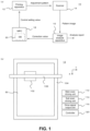
- Fig. 1 is a view describing the printing system 10 that executes the method for adjusting the inkjet printer according to one embodiment of this invention.
- Fig. 1(a) illustrates an example of the configuration of the main part of the printing system 10.
- the printing system 10 may have features identical or similar to known printing systems.
- the printing system 10 may further have a configuration identical or similar to known printing systems other than the illustrated configuration.
- the printing system 10 is a printing system that performs inkjet printing, and includes the printing apparatus 12, a scanner 14, the image analysis apparatus 16, and an MPC 18.
- the printing apparatus 12 is an inkjet printer that executes printing in the printing system 10.
- the printing apparatus 12 includes a plurality of inkjet heads, and prints an adjustment pattern that is a preset test pattern on a medium that is a printing target at the time of adjustment of the printing apparatus 12. The configuration of the printing apparatus 12 will be described in more detail later.
- the scanner 14 is an image reading apparatus that reads an image printed on a medium by the printing apparatus 12.
- the scanner 14 reads an adjustment pattern printed on the medium at the time of adjustment with respect to the printing apparatus 12.
- Use of the scanner 14 also enables reading of the image at high resolution to be performed easily and appropriately.
- a color scanner that can read a full-color image is preferably used.
- the scanner 14 it is conceivable to use a scanner that is connected to a computer, for example, and performs reading of an image under the control of the computer.
- the scanner 14 it is possible to suitably use a scanner having a maximum readable document size of equal to or less than the A4 size, for example.
- a scanner having a reading resolution of equal to or greater than 2400 dpi e.g., about 2400 to 4800 dpi, preferably about 2400 to 3000 dpi.
- This configuration can appropriately execute reading of the adjustment pattern using a commercially available inexpensive PC scanner or the like.
- the computer to which the scanner 14 is connected for example, a general-purpose PC or the like can be suitably used.
- the image analysis apparatus 16 is used as this computer.
- the image analysis apparatus 16 is a computer that performs image analysis on a pattern image indicating an adjustment pattern, and performs image processing on a pattern image generated by reading of the adjustment pattern by the scanner 14.
- the image analysis apparatus 16 performs calculation of a correction value used to control of the operation of the printing apparatus 12, calculation of a numerical value indicating the state of the inkjet head in the printing apparatus 12, and the like.
- the image analysis apparatus 16 can be a computer such as a PC, and performs calculation of a numerical value such as a predetermined correction value based on an adjustment pattern according to an image analysis tool that is a program causing the computer to function as an image analysis apparatus.
- the image analysis apparatus 16 supplies a calculated correction value to the MPC 18.
- the image analysis apparatus 16 generates an analysis result file, which is a file indicating an analysis result, as an analysis report indicating a result of analysis in image processing.
- the numerical values calculated by the image analysis apparatus 16, the operation of the image analysis apparatus 16, and the like will be described in more detail later.
- the MPC 18 is a computer (control PC) that controls the operation of the printing apparatus 12, and controls the operation of the printing apparatus 12 by operating according to a program for controlling the operation of the printing apparatus 12.
- the MPC 18 manages a database 20 that stores control setting values, and controls the operation of the printing apparatus 12 based on the control setting values stored in the database 20.
- the control setting values can be considered to be setting values or the like for controlling the operation of the printing apparatus 12.
- the database 20 is an example of a setting value storage that stores control setting values, and is configured as a part of the MPC 18.
- the control setting values stored in the database 20 are stored in a storage apparatus (e.g., HDD or SSD) of the MPC 18.
- the database 20 stores a plurality of types of control setting values each associated with operations different from one another in the printing apparatus 12.
- the database 20 may be placed outside the MPC 18.
- the MPC 18 causes the database 20 to store, as at least one of the control setting values, the correction value received from the image analysis apparatus 16.
- the MPC 18 controls the operation of the printing apparatus 12.
- Such configuration can appropriately perform adjustment of the operation of the printing apparatus 12 based on the correction value calculated based on the adjustment pattern.
- at least one of the control setting values can be considered to be any of the control setting values or the like stored in the database 20.
- Fig. 1(b) illustrates an example of a configuration of a main part of a printing apparatus 12.
- the printing apparatus 12 may have features identical or similar to known printing apparatuses.
- the printing apparatus 12 may further have a configuration identical or similar to known printing apparatuses other than the illustrated configuration.
- the printing apparatus 12 includes a head unit 102, a table unit 104, a Y bar unit 106, a main scan driving unit 112, a sub scan driving unit 114, a drive signal output unit 116, and a controller 120.
- the head unit 102 is a portion that ejects ink onto a medium 50 that is a printing target.
- the head unit 102 includes a plurality of inkjet heads, and ejects ink from each inkjet head to an ejection position on the medium 50 set according to the resolution of printing.
- each inkjet head ejects ink to at least a part of the ejection position selected according to an image to be printed among the ejection positions set according to the resolution of printing.
- a specific configuration of the head unit 102 will be described in more detail later.
- the table unit 104 is a table-shaped member that holds the medium 50 at a position facing the head unit 102.
- the table unit 104 is a table that holds the medium 50 in a flatbed type printing apparatus, and as illustrated in Fig. 1(b) , the entire medium 50 is placed on the upper surface to hold the medium 50 to face the head unit 102.
- the Y bar unit 106 is a member extending in a width direction of the medium 50 at a position facing the table unit 104 across the medium 50, and holds the head unit 102 at a position facing the medium 50.
- the width direction of the medium 50 is a direction parallel to a main scanning direction (Y direction in Fig. 1(b) ) set in advance in the printing apparatus 12.
- the Y bar unit 106 includes a guide rail or the like that guides movement of the head unit 102 in the main scanning direction, and guides movement of the head unit 102 in the main scanning direction at the time of the main scan.
- the main scan can be considered to be an operation or the like of ejecting ink while moving relatively to the medium 50 in the main scanning direction.
- the main scan driving unit 112 is a driving unit that causes the head unit 102 to perform the main scan. Causing the head unit 102 to perform the main scan can be considered as causing the plurality of inkjet heads in the head unit 102 to perform the main scan or the like.
- the main scan driving unit 112 causes the head unit 102 to perform the main scan by causing each inkjet head in the head unit 102 to eject ink while moving the head unit 102 along the Y bar unit 106.
- the main scan driving unit 112 supplies each inkjet head with the drive signal received from the drive signal output unit 116 under the control of the controller 120, and causes each nozzle in each inkjet head to eject ink according to the image to be printed.
- the drive signal can be considered as a signal or the like for causing each of the plurality of inkjet heads to eject ink.
- the drive signal can also be considered as a signal or the like for driving a drive element (e.g., a piezoelectric element or the like) that ejects ink from the nozzle in each inkjet head.
- a drive element e.g., a piezoelectric element or the like
- the sub scan driving unit 114 is a driving unit that causes the head unit 102 to perform the sub scan. Causing the head unit 102 to perform the sub scan can be considered as causing the plurality of inkjet heads in the head unit 102 to perform the sub scan or the like.
- the sub scan can be considered as an operation or the like of moving relatively to the medium 50 in a sub scanning direction (X direction in Fig. 1(b) ) orthogonal to the main scanning direction.
- the sub scan can also be considered as an operation or the like of changing a position facing the head unit 102 at the time of the main scan on the medium 50.
- the sub scan driving unit 114 changes the region where the ink is ejected in the next main scan in the medium 50 by causing the head unit 102 to perform the sub scan between the main scans. Such configuration can cause the head unit 102 to appropriately perform the main scan with respect to each position of the medium 50.
- the sub scan driving unit 114 causes the head unit 102 to perform the sub scan by moving the Y bar unit 106 together with the head unit 102 by a predetermined sub scanning moving amount under the control of the controller 120 with respect to the table unit 104 whose position is fixed.
- the sub scanning moving amount can be considered as a moving amount or the like in which the plurality of inkjet heads move relatively to the medium 50 in the sub scan.
- the drive signal output unit 116 is an output unit that supplies the plurality of inkjet heads in the head unit 102 with a drive signal. By supplying the drive element in each inkjet head with a drive signal via the main scan driving unit 112, the drive signal output unit 116 causes the ink to be ejected from the nozzle in each inkjet head.
- the controller 120 is a portion including a CPU of the printing apparatus 12, and controls the operation of each unit of the printing apparatus 12 according to a program such as firmware of the printing apparatus 12.
- the controller 120 can also be considered to be a configuration or the like corresponding to a control unit in the printing apparatus 12.
- the controller 120 controls the operation of each unit of the printing apparatus 12 based on the control setting values stored in the database 20.
- the controller 120 operates the units of the printing apparatus 12 based on the control setting values.
- the controller 120 controls the operation of the main scan driving unit 112 based on the control setting values stored in the database 20.
- the main scan driving unit 112 causes the head unit 102 to perform the main scan based on the control setting values.
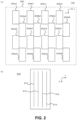
- Fig. 2 is a view describing a specific configuration of the head unit 102.
- Fig. 2(a) illustrates an example of the configuration of the head unit 102.
- Fig. 2(b) illustrates an example of the configuration of one of the inkjet heads 202 in the head unit 102.
- the head unit 102 includes a carriage 200 and a plurality of the inkjet heads 202.
- the carriage 200 is a holding member that holds the plurality of inkjet heads 202 in the head unit 102, and holds the plurality (16) of inkjet heads 202 as distinguished and illustrated by reference signs 202a1 to 202d4 in Fig. 2(a) at positions facing the table unit 104 (see Fig. 1(b) ).
- holding the inkjet head 202 to face the table unit 104 can be considered as holding or the like the inkjet head 202 so that the ink is ejected toward the medium on the table unit 104.
- the carriage 200 holds the plurality of inkjet heads 202 by a configuration in which a plurality of rows of inkjet heads 202 in which a plurality of the inkjet heads 202 are arranged in the sub scanning direction in a staggered arrangement are arranged in the main scanning direction.
- the four inkjet heads 202 illustrated as inkjet heads 202a1 to 202a4 are in a first row arranged in a staggered array.
- the four inkjet heads 202 illustrated as inkjet heads 202b1 to 202b4 are in a second row arranged in a staggered array.
- the four inkjet heads 202 illustrated as inkjet heads 202c1 to 202c4 are in a third row arranged in a staggered array.
- the four inkjet heads 202 illustrated as inkjet heads 202d1 to 202d4 are in a fourth row arranged in a staggered array.
- Arranging the plurality of inkjet heads 202 in a staggered array can be considered as arranging or the like, in the sub scanning direction, the plurality of inkjet heads 202 such that their positions are misaligned (shifted with respect to each other) in the main scanning direction.
- the plurality of inkjet heads 202 may be arranged in the sub scanning direction so as to partially overlap in the sub scanning direction, for example.
- the four inkjet heads 202 arranged in the staggered array are arranged in the sub scanning direction so that the positions are alternately misaligned in the main scanning direction and parts of adjacent inkjet heads 202 overlap in the sub scanning direction.
- the plurality of inkjet heads 202 arranged in the staggered array can be used as one virtual large inkjet head. Specifically, it can be considered that the nozzles of the plurality of inkjet heads 202 arranged in the staggered array are put together to constitute one virtual nozzle row. As illustrated in Fig. 2(a) , the first to fourth rows of the inkjet heads 202 are arranged along the main scanning direction with their positions aligned with respect to the sub scanning direction. In this case, it can be considered that the virtual nozzle rows corresponding to the staggered arrays are lined up in the main scanning direction.
- ink of the same color is ejected by the plurality of inkjet heads 202 arranged in each staggered array (one staggered array), and ink of different colors is ejected by inkjet heads 202 arranged in different staggered arrays.
- ink of the various process colors is ejected by the inkjet heads 202 of the first to fourth rows.
- the process colors can be considered to be basic colors or the like for color expression by subtractive color mixing.
- inks of Y (yellow), M (magenta), C (cyan), and K (black) colors are used as the inks of the process colors. Use of the ink of all these colors enables color printing with high quality to be appropriately performed.
- ink of a color different from other inkjet head 202 in the same staggered array may be ejected by a part of the plurality of inkjet heads 202 arranged in one staggered array.
- Such configuration can eject ink of more colors in the head unit 102.
- eject or the like ink of the same color by the inkjet head 202 of a plurality of staggered arrays are also possible.
- the number and arrangement of the inkjet heads 202 are not limited to the example illustrated in Fig. 2(a) , and can be variously changed.
- the head unit 102 may further have another configuration in accordance with the ink ejected from the inkjet head 202.
- the head unit 102 may further include an ultraviolet light source or the like.
- each of the inkjet heads 202 has a plurality of nozzle rows 212.
- the nozzle row 212 can be considered as a row or the like in which a plurality of nozzles are arranged with their positions in a predetermined nozzle row direction misaligned from one another.
- the nozzle row direction is a direction parallel to the sub scanning direction.
- the plurality of nozzles are arranged in the sub scanning direction at a constant nozzle interval with their positions in the main scanning direction aligned.
- the plurality of nozzle rows 212 are arranged in the main scanning direction with their positions in the sub scanning direction misaligned.
- Fig. 2(b) illustrates an example of the configuration of the inkjet head 202 in a simplified manner for a case where the number of nozzle rows 212 in one inkjet head 202 is four rows.
- the number of nozzle rows 212 in one inkjet head 202 may be other than four rows.
- the number of nozzle rows 212 in one inkjet head 202 is preferably equal to or greater than four rows (e.g., about 4 to 6 rows).
- the image analysis apparatus 16 performs calculation of a numerical value such as a predetermined correction value based on an adjustment pattern according to the image analysis tool.
- a program having the configuration illustrated in Fig. 3 for example, is used as the image analysis tool.
- Fig. 3 illustrates an example of the configuration of the image analysis tool.
- the image analysis tool is a program executed in the image analysis apparatus 16 (see Fig. 1(a) ), and includes a plurality of modules.
- the image analysis tool includes, as a plurality of modules, an analysis tool body 302, a pattern analysis library 304, a plurality of adjustment item libraries 306, and a report creation library 308.
- the analysis tool body 302 is a module serving as a tool body that controls the entire image analysis tool.
- the analysis tool body 302 is an executable file (e.g., a file in an exe format), and performs management of input/output processing (I/O processing) of data with respect to the image analysis tool, input/output processing of data between modules in the image analysis tool, and the like.
- I/O processing input/output processing
- the analysis tool body 302 displays a user interface (UI) on a monitor of the image analysis apparatus 16, for example, and performs reading of a pattern image and a model parameter by selection of a file by the user.
- the pattern image is an image generated by reading, with the scanner 14 (see Fig. 1(a) ), the adjustment pattern printed on the medium.
- the pattern image is stored in the storage apparatus of the image analysis apparatus 16, and is read into the image analysis tool by being selected by the user through the user interface.
- the pattern image read into the image analysis tool can be considered as an analysis image or the like that is an analysis target.
- the model parameter is a parameter set according to the model of the printing apparatus 12 (see Fig. 1(a) ) used for printing of the adjustment pattern.
- model parameter can cause the image analysis tool to perform an operation according to the model of the printing apparatus 12. It becomes possible to use a common image analysis tool for a plurality of types of models of printing apparatuses.
- the model parameter for example, it is conceivable to use a parameter indicating the arrangement of the inkjet heads, the configuration of the inkjet head, or the like in the head unit 102 (see Fig. 2(a) ).
- the parameter indicating the arrangement of the inkjet heads for example, it is conceivable to use a parameter indicating the number of inkjet heads or the number of arrangements in the staggered arrangement.
- the image analysis apparatus 16 outputs correction value data and an analysis report as an output in the operation executed according to the image analysis tool.
- the image analysis apparatus 16 outputs, as correction value data, a file indicating the correction value calculated by the image analysis apparatus 16.
- an analysis report an analysis result file indicating an analysis result is output.
- the image analysis apparatus 16 performs calculation of the correction value, generation of the analysis result file, and the like by the operation executed according to the image analysis tool.
- the correction value data can also be considered as a file or the like for feeding back the correction value to the printing apparatus 12.
- the image analysis apparatus 16 outputs the correction value data by generating a file indicating the correction value in a predetermined format.
- a program for managing information stored in the database 20 is executed by the image analysis apparatus 16 or another computer, thereby causing the database 20 to store the correction value.
- the correction value may be directly stored in the database 20 in the operation of the image analysis apparatus 16 executed according to the image analysis tool.
- the analysis result file it is conceivable to use a file, for example, in a pdf format or a table calculation file format.
- the analysis report output by the analysis result file can be considered as a report or the like in which the adjustment level in the printing apparatus 12, for example, is quantified and organized in a format that is easy for a person to see. It is conceivable to use the analysis report for evidence management of the adjustment level, for example.
- Each of the pattern analysis library 304, the plurality of adjustment item libraries 306, and the report creation library 308 is a module that functions as a library.
- a module of these libraries a file in a dynamic link library format (DLL format) is used.
- the pattern analysis library 304 is a library for interpreting a pattern image, and calls a necessary module from the plurality of adjustment item libraries 306 based on a result of interpreting the pattern image.
- the pattern analysis library 304 causes the plurality of adjustment item libraries 306 to perform various analyses on the pattern image.
- Each of the plurality of adjustment item libraries 306 is a library that performs analysis for various items (adjustment items) that is analysis targets by the image analysis tool.
- Each of the plurality of adjustment item libraries 306 is a library for items different from one another, and is called from the pattern analysis library 304 as necessary to execute processing related to the corresponding item.
- the image analysis tool of this example is configured to be able to add a necessary adjustment item library 306 in a case where the number of items to be analyzed increases later.
- the adjustment item library 306 for head tilt analysis performs analysis of the attachment angle of the inkjet head 202 (see Fig. 2(b) ) with respect to the carriage 200 (see Fig. 2(a) ).
- the attachment angle of the inkjet head 202 can be considered as an angle or the like at which the long direction of the inkjet head 202 is misaligned with respect to a predetermined correct orientation.
- the adjustment item library 306 for head front-rear analysis performs analysis of the position in the sub scanning direction, which becomes the front-rear direction, for each inkjet head 202 held in the carriage 200.
- the adjustment item library 306 for head stagger analysis performs analysis of the positional relationship in the front-rear direction between the adjacent inkjet heads 202 for the plurality of inkjet heads 202 arranged in a staggered array.
- the adjustment item library 306 for head voltage analysis performs analysis of the voltage of the drive signal supplied to each inkjet head 202.
- the adjustment item library 306 for dot position analysis performs analysis of the position of the ink dot formed by the ink ejected from the nozzle in the nozzle row of each inkjet head 202.
- the adjustment item library 306 for feed analysis performs analysis of the sub scanning moving amount in the sub scan.
- the report creation library 308 generates an analysis result file based on the results of the analyses performed in the plurality of adjustment item libraries 306.
- the report creation library 308 receives the analysis result in each adjustment item library 306 via the analysis tool body 302 and the pattern analysis library 304.
- the report creation library 308 outputs an analysis result file via the analysis tool body 302.
- the image analysis apparatus 16 causes the database 20 to store the correction value.
- the correction value is calculated in accordance with the result of the analysis to be executed in at least a part of the plurality of adjustment item libraries 306.
- the analysis tool body 302 receives the correction value from the adjustment item library 306 via the pattern analysis library 304, and outputs correction value data indicating the received correction value.
- the head tilt analysis, the head front-rear analysis, and the head stagger analysis can be considered as analyses related to mechanical adjustment.
- the head voltage analysis, the dot position analysis, and the feed analysis can be considered as analyses related to adjustment of printing operation (print adjustment) other than mechanical adjustment.
- the correction value is calculated in the adjustment item library 306 for dot position analysis and the adjustment item library 306 for feed analysis among the adjustment item library 306 related to print adjustment.
- the result of the analysis in the adjustment item library 306 not for calculating the correction value is reflected in the analysis result file.
- the analysis result in all the adjustment item libraries 306 including the analysis result in the adjustment item library 306 for calculating the correction value is reflected in the analysis result file.
- FIG. 4 is a view describing an example of the analysis executed in the adjustment item library 306, and illustrates an example of the analysis performed in the adjustment item library 306 for dot position analysis among the plurality of adjustment item libraries 306 in the image analysis tool.
- the printing apparatus 12 When image analysis is performed by the image analysis apparatus 16 (see Fig. 1(a) ), the printing apparatus 12 (see Fig. 1(a) ) is caused to print an adjustment pattern in accordance with the content of the analysis to be executed. Therefore, when the image analysis is performed in the adjustment item library 306 for dot position analysis, the printing apparatus 12 is caused to print the adjustment pattern including the misalignment amount detection pattern 400.
- the misalignment amount detection pattern 400 can be considered as a pattern or the like for detecting the dot position misalignment amount.
- the dot position misalignment amount can be considered as a misalignment amount or the like of the position of the dot occurring in each of the plurality of nozzle rows in the head unit 102 (see Fig.
- the position of the dot can be considered as the position or the like of the dot of the ink formed on the medium by ejecting ink from the nozzle included in each of the plurality of nozzle rows in the head unit 102.
- the plurality of nozzle rows in the head unit 102 can be considered as a plurality of nozzle rows or the like included in the plurality of inkjet heads 202 (see Fig. 2 ) held by the carriage 200 (see Fig. 2(a) ) in the head unit 102.
- the plurality of nozzle rows can be considered as 64 nozzle rows or the like included in the 16 inkjet heads 202.
- the position of the dot can be considered as the position or the like of the dot of the ink formed on the medium by ejecting ink from the nozzle included in each of the plurality of nozzle rows in the plurality of inkjet heads 202.
- a pattern illustrated in Fig. 4(a) is used.
- Fig. 4(a) illustrates an example of the misalignment amount detection pattern 400.
- the misalignment amount detection pattern 400 is a pattern for ejecting ink from a plurality of nozzle rows to the same position in the main scanning direction. Specifically, at the time of printing of the adjustment pattern, one nozzle row in one inkjet head 202 among the plurality of inkjet heads 202 in the printing apparatus 12 is selected as a reference nozzle row.
- each nozzle row other than the reference nozzle row is sequentially selected, and the printing apparatus 12 is caused to print a pattern for ejecting ink from two nozzle rows including the reference nozzle row and each nozzle row other than the reference nozzle row to the same position in the main scanning direction.
- this causes the printing apparatus 12 to print the misalignment amount detection pattern 400 including the multiple line 402 of the number corresponding to the number of the nozzle rows included in the printing apparatus 12.
- the multiple line 402 can be considered as a plurality of lines or the like drawn at the same position.
- the multiple line 402 can be considered as double lines or the like drawn by ejecting ink from two nozzle rows to the same position in the main scanning direction. In this case, ejecting the ink to the same position can be considered as ejecting the ink to the same position according to specification or the like. Therefore, in the multiple line 402 actually drawn, the positions of the ink dots formed by the ink ejected from the different nozzle rows may be misaligned in the main scanning direction.
- Such pattern of the multiple line including the multiple line 402 can also be considered as a pattern or the like in which a plurality of lines are drawn at the same position according to specification in the main scanning direction by drawing a line extending in the sub scanning direction with ink ejected from each nozzle row.
- 64 multiple lines 402 are drawn as distinguished by adding numerals 1 to 64 in Fig. 4(a) corresponding to the 64 nozzle rows included in the plurality of inkjet heads 202 in the printing apparatus 12.
- Each of the multiple lines 402 can be considered as a line or the like drawn by the reference nozzle row and a nozzle row other than that.
- one of the multiple line 402 corresponds to the reference nozzle row.
- the multiple line 402 corresponding to the reference nozzle row can be exceptionally considered as a line or the like drawn only with the reference nozzle row. For example, when the nozzle row corresponding to the number 1 in Fig.
- the multiple line 402 denoted by the numeral 1 is a line drawn only with the reference nozzle row.
- the lines denoted by the numerals 2 to 64 are then lines drawn using the reference nozzle row and a nozzle row other than that.
- misalignment of the position of the dot has not occurred between the two nozzle rows drawing the one multiple line 402
- the lines drawn by those nozzle rows overlap at the same position in the main scanning direction.
- misalignment of the position of the dot not having occurred between the two nozzle rows can be considered as misalignment of the relative position of the dot based on the position of the dot formed in the reference nozzle row not having occurred.
- misalignment of the position of the dot not having occurred between the two nozzle rows drawing the one multiple line 402 can be considered as misalignment of the position of the dot formed in the other nozzle row not having occurred with respect to the position of the dot formed in the reference nozzle row in the main scanning direction.
- misalignment of the position of the dot not having occurred can also be considered as the misalignment amount of the position of the dot being falling within a predetermined allowable range or the like.
- the position of the line drawn by each nozzle row is misaligned in the main scanning direction as illustrated in Fig. 4(b) when the multiple line 402 is enlarged and observed.
- Fig. 4(b) is an enlarged view of the one multiple line 402.
- the printing apparatus 12 draws each multiple line 402 by using the reference nozzle row and a nozzle row other than that. Therefore, each multiple line 402 can be considered to be configured by a reference nozzle line 412 and an adjustment nozzle line 414 as illustrated in Fig. 4(b) .
- the reference nozzle line 412 is a line drawn by the reference nozzle row.
- the adjustment nozzle line 414 is a line drawn by a nozzle row other than the reference nozzle row.
- Each of the reference nozzle line 412 and the adjustment nozzle line 414 can be considered as lines or the like drawn by an arrangement of ink dots formed by the ink ejected to the same position in the main scanning direction by a plurality of nozzles included in one nozzle row.
- ejecting the ink to the same position in the main scanning direction by the plurality of nozzles included in one nozzle row can be considered as ejecting the ink at the same timing during the main scan or the like.
- the adjustment item library 306 for dot position analysis measures the distance in the main scanning direction between the reference nozzle line 412 and the adjustment nozzle line 414 by image processing on each multiple line 402 included in the misalignment amount detection pattern 400 based on the pattern image obtained from the misalignment amount detection pattern 400.
- the pattern image obtained from the misalignment amount detection pattern 400 can be considered as a pattern image or the like generated by reading, with the scanner 14 (see Fig. 1(a) ), the adjustment pattern including the misalignment amount detection pattern 400.
- a distance corresponding to the relative position of the adjustment nozzle line 414 with respect to the reference nozzle line 412 is calculated by image processing with a predetermined orientation as a positive direction and the opposite side as a negative direction.
- this measurement distance can be considered to correspond to the misalignment amount of the dot position between two nozzle rows drawing the one multiple line 402.
- the dot position misalignment amount can be calculated based on one reference nozzle row for each nozzle row based on the measurement distance with respect to the multiple line 402 corresponding to each nozzle row other than the reference nozzle row.
- the adjustment item library 306 for dot position analysis calculates the dot position misalignment amount based on one reference nozzle row for each nozzle row in the printing apparatus 12 based on the pattern image.
- a dot position correction value which is a correction value corresponding to the dot position misalignment amount, is further calculated based on the calculated dot position misalignment amount.
- the dot position correction value is an example of a correction value indicated by correction value data.
- Such configuration can appropriately perform analysis of the position of the ink dot formed by the ink ejected from the nozzle in the nozzle row of each inkjet head 202 in the adjustment item library 306 for dot position analysis.
- each of the reference nozzle line 412 and the adjustment nozzle line 414 may be a line formed by some nozzles in one nozzle row.
- the reference nozzle line 412 is considered to be drawn by selecting some of the plurality of nozzles in the reference nozzle row as reference nozzles and ejecting ink from the reference nozzles.
- the adjustment nozzle line 414 is drawn by selecting some of the plurality of nozzles in a nozzle row (nozzle row that is an adjustment target) other than the reference nozzle row as an adjustment nozzle and ejecting ink from the adjustment nozzle.
- the ink dots configuring each of the reference nozzle line 412 and the adjustment nozzle line 414 can be formed at a distance in the sub scanning direction. This can more appropriately identify with high accuracy the position of each ink dot. By identifying with high accuracy the positions of the ink dots configuring the reference nozzle line 412 and the adjustment nozzle line 414, it becomes possible to determine with higher accuracy and the like the positions in the main scanning direction of the reference nozzle line 412 and the adjustment nozzle line 414.
- the printing apparatus 12 is considered to cause the plurality of inkjet heads 202 to perform reciprocating main scan. Causing the inkjet head 202 to perform the reciprocating main scan can be considered as causing the inkjet head 202 to perform an outward main scan of moving the inkjet head 202 in one orientation in the main scanning direction and a return main scan of moving the inkjet head 202 in the other orientation in the main scanning direction.
- the dot position misalignment amount is considered to be different between the outward main scan and the return main scanning, for example. Therefore, the dot position misalignment amount is preferably calculated individually for each orientation of movement of the inkjet head 202 in the outward and return main scans. In this case, it is considered to cause the printing apparatus 12 to print the misalignment amount detection pattern 400 for each orientation of movement of the inkjet head 202.
- the misalignment amount detection pattern 400 includes the multiple lines 402 by the number corresponding to the number of nozzle rows in the printing apparatus 12.
- the number of nozzle rows in the printing apparatus 12 is considered to vary depending on the model, specification, and the like of the printing apparatus 12. Therefore, as the misalignment amount detection pattern 400, it is conceivable to use a pattern dynamically determined in accordance with the configuration of the printing apparatus 12.
- the image analysis tool performs analysis on the misalignment amount detection pattern 400 in accordance with the configuration of the printing apparatus 12 based on the model parameter.
- This configuration can use a common image analysis tool for the printing apparatuses 12 having various configurations.
- the image analysis tool of this example can also be considered to be particularly suitably usable when the number of target nozzle rows is large.
- the total number of nozzle rows that is an analysis target can be considered to be, for example, 20 or more, preferably 30 or more.
- the total number of nozzle rows that is an analysis target can be considered as the number of nozzle rows corresponding to a plurality of multiple lines 402 included in the misalignment amount detection pattern 400, the number of nozzle rows included in the printing apparatus 12, and the like.
- the inkjet head 202 it is also conceivable to use a configuration in which the volume of ink ejected from each nozzle can be changed in a plurality of stages. In this case, it is also conceivable that a difference occurs depending on the volume of the ink regarding the dot position misalignment amount.
- the printing apparatus 12 may be caused to draw the misalignment amount detection pattern 400 including the individual multiple lines 402 for each volume of ink.
- the image analysis apparatus 16 calculates the dot position misalignment amount and the dot position correction value for each volume of ink.
- the image analysis tool further includes the adjustment item library 306 for analysis other than dot position analysis.
- the printing apparatus 12 in order to perform analysis in the adjustment item library 306 for analysis other than dot position analysis, it is conceivable to cause the printing apparatus 12 to print a pattern including a pattern other than the misalignment amount detection pattern 400 as the adjustment pattern. Also in this case, it is conceivable to use a pattern dynamically determined in accordance with the configuration or the like of the printing apparatus 12.
- causing the printing apparatus 12 to print an adjustment pattern including patterns corresponding to a plurality of types of adjustment item libraries 306 it is conceivable to cause a pattern divided for each inkjet head 202, for example, to be printed on a medium.
- Such configuration can easily and appropriately grasp the correspondence relationship between the pattern printed on the medium and the inkjet head 202.
- each multiple line 402 configuring the misalignment amount detection pattern 400 it is considered to draw or the like with, in the pattern for each inkjet head 202, the multiple line 402 corresponding to the nozzle row in each inkjet head 202 differently from the arrangement illustrated in Fig. 4(a) .
- the adjustment pattern illustrated in Fig. 5 as the pattern divided for each inkjet head 202.
- Fig. 5 is a view describing an adjustment pattern configured with a pattern divided for each inkjet head 202.
- Fig. 5(a) illustrates an example of the adjustment pattern.
- the image analysis tool performs analysis using the plurality of types of adjustment item libraries 306 (see Fig. 3 )
- the adjustment pattern includes a scanner set mark 502, a tilt correction line 504, a register mark 506, and a plurality of the head-by-head patterns 508.
- the scanner set mark 502, the tilt correction line 504, and the register mark 506 are configurations for correcting the position, tilt, and the like of the pattern image generated by reading the adjustment pattern by the scanner 14 (see Fig. 1(a) ).
- the scanner set mark 502 is a mark used as a reference of a position when an image is read by the scanner 14.
- the scanner set mark 502 can also be considered as a mark or the like that becomes an origin (scan image origin) of an image scanned by the scanner 14.
- the tilt correction line 504 is a line used for performing correction of the tilt with respect to the pattern image generated by reading the adjustment pattern by the scanner 14.
- the register mark 506 is a mark used as a reference of a position with respect to the plurality of head-by-head patterns 508.
- the register mark 506 can also be considered as a mark or the like for defining position information of the plurality of head-by-head patterns 508.
- the plurality of head-by-head patterns 508 are parts corresponding to the pattern divided for each inkjet head 202.
- the head-by-head patterns 508 are printed on the medium 50 corresponding to the respective inkjet heads 202 in the printing apparatus 12.
- a plurality of patterns 510 are printed as the respective head-by-head patterns 508.
- Fig. 5(b) is a view illustrating an example of the configuration of the head-by-head pattern 508, and illustrates an example of the configuration of the head-by-head pattern 508 when printing the head-by-head pattern 508 including the plurality of patterns 510 distinguished and illustrated as patterns 510a to 5 10e for one inkjet head 202.
- each of the patterns 510a to 510e it is conceivable to use a pattern in accordance with an item to be analyzed in each adjustment item library 306. In this case, it is also conceivable to use a plurality of patterns among the patterns 510a to 510e for one adjustment item library 306.
- the adjustment item library 306 When calculating the dot position misalignment amount by the adjustment item library 306 for dot position analysis, it is preferable to individually calculate the dot position misalignment amount for each orientation of movement of the inkjet head 202 in the outward and return main scans. Therefore, in this case, it is conceivable to use one of the patterns 510a to 510e for calculation of the dot position misalignment amount in the return path, and use the any other one of the patterns for calculation of the dot position misalignment amount in the outward path. Specifically, when using the head-by-head pattern 508 having the configuration illustrated in Fig.
- the patterns 510a and 5 10b it is conceivable to print a pattern used for analysis in the adjustment item library 306 for dot position analysis as the patterns 510a and 5 10b.
- the pattern 5 10a is used for calculation of the dot position misalignment amount in the return path
- the pattern 510b is used for calculation of the dot position misalignment amount in the outward path.
- the patterns 510a and 5 10b it is conceivable to print a pattern including the multiple line 402 for the nozzle row of the inkjet head 202 corresponding to the head-by-head pattern unit 508 in the misalignment amount detection pattern 400 (see Fig. 4(a) ), for example.
- the patterns 510c to 510e other than the patterns 510a and 510b for analysis in the adjustment item libraries 306 other than for dot position analysis.
- each of the patterns 510c to 510e for analysis in any of the adjustment item library 306 for head tilt analysis, for head front-rear analysis, for head stagger analysis, for head voltage analysis, and for feed analysis.
- the pattern 510c it is conceivable to print a pattern used for analysis in the adjustment item library 306 for head stagger analysis, for example.
- the pattern 510d for example, it is conceivable to print a pattern used for analysis in the adjustment item library 306 for head tilt analysis.
- the pattern 5 10e for example, it is conceivable to print a pattern used for analysis in the adjustment item library 306 for head front-rear analysis.
- any of the patterns 510c to 510e it is also conceivable to print a pattern used for analysis in the adjustment item library 306 for head voltage analysis.
- the head-by-head pattern 508 further including a pattern used for analysis in the adjustment item library 306 for head voltage analysis.
- a pattern used for analysis in the adjustment item library 306 for head tilt analysis it is conceivable to print a pattern in which lines overlap on one end side and the other end side (back side and front side) of the inkjet head 202 in the sub scanning direction by two main scans having the sub scan in between, for example.
- a line parallel to the sub scanning direction is drawn by simultaneously ejecting ink with at least some nozzles (e.g., the nozzle on the back side) of any nozzle row of each inkjet head 202.
- the line parallel to the sub scanning direction can be considered as a line or the like drawn on the medium 50 by simultaneously ejecting the ink from the plurality of nozzles in the nozzle row at a predetermined timing at the time of the main scan.
- the line parallel to the sub scanning direction can also be considered as a line or the like that becomes parallel to the sub scanning direction when the inkjet head 202 is not tilted. Then, in the second main scan performed having the sub scan in between, by simultaneously ejecting the ink with at least some of the nozzles (e.g., the nozzle on the front side) in the same nozzle row as used in the first main scan, a line is further drawn at a position overlapping the line drawn in the first main scan.
- the inkjet head 202 drawing the two lines is tilted, the two lines correctly overlap.
- the misalignment of the position between the two lines increases according to the magnitude of the tilt.
- the distance between such two lines is measured by image processing, and the magnitude of the tilt of the inkjet head 202 is calculated based on the measurement result.
- the magnitude of the tilt of one inkjet head 202 is preferably calculated based on the result of performing the measurement at a plurality of positions different from one another (e.g., about four positions).
- the plurality of inkjet heads 202 arranged side by side in the main scanning direction can be considered as the inkjet heads 202 arranged in line or the like.
- the same nozzle in the plurality of inkjet heads 202 can be considered as a nozzle or the like in which the position in the sub scanning direction is the same position.
- the distance between such lines is measured by image processing, and the misalignment amount of the position in the front-rear direction of the inkjet head 202 is calculated based on the measurement result.
- the overlapping part can be considered as a part where the ink can be ejected by the both inkjet heads 202 in the range in the sub scanning direction where the ink can be ejected by two adjacent inkjet heads 202 in the sub scanning direction.
- the nozzle at the overlapping part in the reference inkjet head 202 is caused to draw a first line having a predetermined length extending in the main scanning direction.
- the nozzle at the overlapping part in the inkjet head 202 other than the reference inkjet head 202 is caused to draw a second line extending in the main scanning direction with a length different from that of the first line.
- the first line it is conceivable to draw a long line having a predetermined length.
- the second line a short line shorter than the first line.
- the long line can be considered as a line or the like having a predetermined length relatively longer than the short line.
- the short line can be considered as a line or the like having a predetermined length relatively shorter than the long line.
- the distance (distance in the sub scanning direction) between the lines (e.g., the long line and the short line) drawn by the respective inkjet heads 202 becomes a predetermined distance.
- the misalignment of the distance between the lines drawn by the respective inkjet heads 202 increases according to the magnitude of the misalignment. Therefore, by measuring the distance between the lines drawn by the respective inkjet heads 202, it is possible to detect the misalignment amount from the correct positional relationship in the staggered arrangement.
- the adjustment item library 306 for head stagger analysis measures the distance between such lines by image processing, and calculates, based on the measurement result, the misalignment amount from the correct positional relationship in the staggered arrangement. In this case, it is conceivable to calculate the misalignment amount of the position of another inkjet head 202 based on one of the inkjet heads 202. It is conceivable to calculate the misalignment amount of the position of each inkjet head 202 by a mean value of the misalignment amounts obtained from a plurality of lines (e.g., about eight lines).
- the misalignment amount of the averaged position may be calculated by regarding the part where the plurality of lines are drawn as a rectangular pattern and obtaining the distance in the sub scanning direction between the rectangular patterns.
- the adjustment item library 306 for head voltage analysis it is conceivable to print a pattern with which the color density of the region to be printed by each inkjet head 202 can be confirmed, for example.
- the voltage of the drive signal supplied to the inkjet head 202 is appropriate, the color density of the region to be printed by the inkjet head 202 becomes a predetermined density set in advance.
- the voltage of the drive signal is inappropriate, misalignment occurs in the size of the ink dot formed by the ink ejected from the inkjet head 202 according to the misalignment of the voltage. In this case, it is considered that the ink is not appropriately ejected, and the ink becomes mist.
- the adjustment item library 306 for head voltage analysis the color density of the region to be printed by each inkjet head 202 is measured by image processing, and based on the measurement result, it is determined whether or not the voltage of the drive signal supplied to the inkjet head 202 that has formed the dot is appropriate. A numerical value indicating the misalignment amount of the voltage of the drive signal is calculated as necessary.
- a pattern used for analysis in the adjustment item library 306 for feed analysis it is conceivable to print a pattern with which the sub scanning moving amount in the sub scan can be confirmed. As such pattern, it is conceivable to perform two main scans performed with the sub scan in between and draw a pattern in which ends of regions (bands) where ink can be ejected are connected in each main scan. In this case, if the sub scanning moving amount is appropriate, it is possible to appropriately perform printing in a state where the end of the band is inconspicuous. On the other hand, if the sub scanning moving amount is inappropriate, a black streak or a white streak extending in the main scanning direction occurs at the position of the end of the band.
- the black streak can be considered as a streak-like part where printing is performed in a darker state than the surroundings by performing double printing, for example.
- the white streak can be considered as a streak-like part where the color of the medium 50 stands out due to the ink not being ejected, for example.
- the adjustment item library 306 for feed analysis the presence or absence of a black streak or a white streak and the width (width in the sub scanning direction) thereof are measured by image processing, thereby calculating the misalignment amount of the sub scanning moving amount.
- the operation of calculating the misalignment amount of the sub scanning moving amount can also be considered as an example of the operation of calculating the sub scanning moving amount.
- the pattern used for the analysis in each adjustment item library 306 is not limited to the above pattern, and use of various patterns is considered.
- a pattern used for analysis in each adjustment item library 306 a pattern that is the identical or similar to a known pattern used for the identical or similar purpose may be used.
- the known pattern needs not be a pattern used for measurement in image processing as in this example, but may be a pattern for confirming the state by visual observation of the user or the like.
- Fig. 6 is a flowchart showing an example of the operation of adjustment of the printing apparatus 12 executed in the printing system 10.
- step S102 the printing apparatus 12 is caused to print an adjustment pattern on the medium (step S102).
- the operation of step S 102 is an example of the operation of the pattern printing stage.
- the printing apparatus 12 executes printing of the adjustment pattern in response to an instruction of the MPC 18 (see Fig. 1(a) ).
- the MPC 18 causes the printing apparatus 12 to print an adjustment pattern dynamically generated in accordance with the configuration of the printing apparatus 12.
- the MPC 18 causes the printing apparatus 12 to print, as the adjustment pattern an adjustment pattern generated in accordance with the item of adjustment to be executed. Due to this, the MPC 18 causes the printing apparatus 12 to print an adjustment pattern including a pattern corresponding to the adjustment item according to the adjustment item to be executed.
- the MPC 18 causes the printing apparatus 12 to print the adjustment pattern including the misalignment amount detection pattern 400.
- the printing apparatus 12 causes the printing apparatus 12 to print an adjustment pattern including a plurality of types of patterns respectively corresponding to a plurality of adjustment items.
- the MPC 18 causes the printing apparatus 12 to print an adjustment pattern including a misalignment amount detection pattern and an attachment state detection pattern as such adjustment pattern.
- the attachment state detection pattern can be considered as a pattern or the like for detecting the attachment state, for example.
- the attachment state can be considered as a state or the like in which each inkjet head 202 is attached to the carriage 200 in the head unit 102 of the printing apparatus 12 (see Fig. 2(a) ).
- the attachment state is a state detected by head tilt analysis, head front-rear analysis, and head stagger analysis, which are analyses related to mechanical adjustment among various analyses executed by the plurality of adjustment item libraries 306 in the image analysis tool.
- the attachment state detection pattern can be considered as a pattern or the like used for analysis in at least any of the adjustment item library 306 for head tilt analysis, for head front-rear analysis, and for head stagger analysis, for example.
- the image analysis apparatus 16 detects at least any of the tilt of the inkjet head, the positional misalignment in a predetermined front-rear direction, and the positional misalignment in the staggered arrangement, for example.
- the MPC 18 may cause the printing apparatus 12 to print an adjustment pattern including a sub scanning moving amount detection pattern and a voltage detection pattern according to an item of adjustment to be executed.
- the sub scanning moving amount detection pattern can be considered as a pattern or the like for detecting the sub scanning moving amount.
- the voltage detection pattern can be considered as a pattern or the like for detecting the voltage of the drive signal received by each of the plurality of inkjet heads 202 in the printing apparatus 12.
- the sub scanning moving amount detection pattern can be considered as a pattern or the like used for analysis in the adjustment item library 306 for feed analysis.
- the voltage detection pattern can be considered as a pattern or the like used for analysis in the adjustment item library 306 for head voltage analysis.
- the printing apparatus 12 prints the adjustment pattern within a printing range of equal to or less than the A4 size, for example, onto the medium.
- a commercially available inexpensive PC scanner or the like can be used as the scanner 14 (see Fig. 1(a) ).
- the printing apparatus 12 prints the adjustment pattern onto a medium having equal to or less than the A4 size smaller than the medium of the maximum size that can be held by the table unit 104.
- the printing apparatus 12 prints the adjustment pattern on an A4 size medium.
- Such operation can also be considered as an operation or the like of printing an adjustment pattern within a printing range narrower than a printable range in the printing apparatus 12.
- the maximum range or the like in which printing can be performed on the table unit 104 (see Fig. 1(b) ) in the printing apparatus 12 can be considered.
- the scanner 14 it is conceivable to use a scanner having a reading resolution of equal to or greater than 2400 dpi, for example.
- the range in which the adjustment pattern is printed is preferably the equal to or less than the A4 size.
- a plurality of media of equal to or less than the A4 size may be used as necessary.
- the MPC 18 causes the printing apparatus 12 to print the adjustment pattern on each of the plurality of media.
- the MPC 18 can also be considered as a part of the adjustment pattern for the pattern to be printed on each medium.
- Such configuration can cause the printing apparatus 12 to print all necessary patterns by being divided into a plurality of media, even when all necessary patterns cannot be printed with one A4 size medium or the like.
- step S104 the medium on which the adjustment pattern is printed is read by the scanner 14, thereby generating a pattern image indicating the adjustment pattern
- step S106 the image analysis apparatus 16 performs analysis on the pattern image
- the operation in step S 104 is an example of the operation of the pattern reading stage.
- the operation in step S 106 is an example of the operation of the analyzing stage.
- the operation of step S106 is also an example of the operation of causing the computer to perform analysis processing.
- the reading of the image by the scanner 14 in step S104 may be performed in an identical or similar manner to a known method for reading the image by the scanner 14, for example.
- step S106 the image analysis apparatus 16 executes predetermined image processing, calculation, and the like as analysis on the pattern image. Due to this, the image analysis apparatus 16 performs calculation of a correction value used for control of the operation of the printing apparatus 12 and calculation of a numerical value indicating the state of the inkjet head in the printing apparatus 12.
- step S108 After the calculation of the correction value is performed in step S 106, update of the control setting values stored in the database 20 (see Fig. 1(a) ) is performed based on the correction value (step S108).
- the operation in step S108 is an example of the operation of the setting value updating stage.
- the setting value updating stage can be considered as a stage or the like of updating at least one of the control setting values based on the analysis result in the analyzing stage.
- the image analysis apparatus 16 outputs correction value data and an analysis result file based on the analysis result in step S 106. Then, by the image analysis apparatus 16 or the other computer executing a program for managing information stored in the database 20, the database 20 is caused to store the correction value in based on the correction value data.
- steps S 102 to S108 it is conceivable to perform the analysis operation in step S106 as illustrated in Fig. 7 .
- Fig. 7 is a flowchart showing an example of the operation of the image analysis apparatus 16 (see Fig. 1(a) ) in step S106 in Fig. 6 .
- Fig. 7 more specifically shows an example of the numerical value calculated by the image analysis apparatus 16 in step S106 and the operation of the image analysis apparatus 16.
- the image analysis apparatus 16 is a computer that performs image analysis on a pattern image by performing image processing on the pattern image generated by reading of an adjustment pattern by the scanner 14 (see Fig. 1(a) ), and performs calculation of a correction value and generation of an analysis result file (analysis report) by performing analysis of the pattern image by various adjustment item libraries 306 (see Fig. 3 ) in the image analysis tool.
- FIG. 7 illustrates an example of the operation of the image analysis apparatus 16 in a case of performing analysis of the pattern image using all of the plurality of adjustment item libraries 306 specifically illustrated in Fig. 3 .
- a modification of the operation of the image analysis apparatus 16 only a part of the operation shown in Fig. 7 may be executed according to the item of adjustment to be executed by the printing system 10.
- the image analysis apparatus 16 executes analysis in the adjustment item library 306 for head tilt analysis, for head front-rear analysis, for head stagger analysis, for head voltage analysis, for dot position analysis, and for feed analysis in the image analysis tool based on the pattern image and the model parameter. Specifically, the image analysis apparatus 16 first performs analysis related to the dot position misalignment amount by the adjustment item library 306 for dot position analysis (step S202). In step S202, the image analysis apparatus 16 detects the dot position misalignment amount regarding the position of the ink dot formed on the medium by performing the above image processing based on the part indicating the misalignment amount detection pattern in the pattern image.
- the image analysis apparatus 16 performs analysis related to the sub scanning moving amount (feed amount) by the adjustment item library 306 for feed analysis (S204).
- the image analysis apparatus 16 detects the sub scanning misalignment amount, which is the misalignment amount of the sub scanning moving amount, by the image processing executed based on the part indicating the sub scanning moving amount detection pattern in the pattern image.
- the operations in steps S202 and S204 are examples of the operation of the misalignment amount detecting stage.
- the operations of steps S202 and S204 are also examples of the operation of causing the computer to perform the misalignment amount detection processing.
- the image analysis apparatus 16 performs analysis related to the attachment state of the plurality of inkjet heads 202 (see Fig. 2(a) ) to the carriage 200 by the adjustment item library 306 for head tilt analysis, for head front-rear analysis, and for head stagger analysis (step S206).
- the adjustment item library 306 for head tilt analysis, for head front-rear analysis, and for head stagger analysis can be considered as the adjustment item library 306 for detecting the attachment state.
- the image analysis apparatus 16 calculates an attachment state numerical value, which is a numerical value indicating the attachment state, by the image processing executed based on the part indicating the attachment state detection pattern in the pattern image.
- the image analysis apparatus 16 performs analysis of the attachment angle of the inkjet head 202 with respect to the carriage 200, analysis of the position of each inkjet head 202 in the sub scanning direction, which becomes the front-rear direction, and analysis of the positional relationship in the front-rear direction between the inkjet heads 202 adjacent to each other in the staggered arrangement.
- the attachment state numerical value numerical values indicating the results of these analyses are calculated.
- the image analysis apparatus 16 performs analysis of the voltage of the drive signal supplied to each inkjet head 202 by the adjustment item library 306 for head voltage analysis (step S208).
- step S208 the image analysis apparatus 16 calculates a voltage-corresponding numerical value, which is a numerical value corresponding to the voltage of the drive signal received by each of the plurality of inkjet heads 202, by the image processing executed based on the part indicating the voltage detection pattern in the pattern image.
- the operations in steps S206 and S208 are examples of the operation of the numerical value calculating stage.
- the operations of steps S206 and S208 are also examples of the operation of causing the computer to perform the numerical value calculation processing.
- step S210 the image analysis apparatus 16 makes a determination of the analysis result (step S210).
- the operation in step S210 is an example of the operation of the determining stage.
- the operation of step S210 is also an example of the operation of causing the computer to perform the determination processing.
- the image analysis apparatus 16 determines whether or not the dot position misalignment amount falls within the reference numerical value range of the dot position misalignment amount based on the analysis result in step S202.
- the reference numerical value range of the dot position misalignment amount can be considered as a reference numerical value range or the like set in advance for the dot position misalignment amount.
- the image analysis apparatus 16 determines whether or not the sub scanning moving amount falls within the reference numerical value range of the sub scanning moving amount based on the result of the analysis in step S204.
- the reference numerical value range of the sub scanning moving amount can be considered as a reference numerical value range or the like set in advance for the sub scanning moving amount.
- the image analysis apparatus 16 determines whether or not the attachment state numerical value falls within the reference numerical value range of the attachment state numerical value based on the result of the analysis in step S206.
- the reference numerical value range of the attachment state numerical value can be considered as a reference numerical value range or the like set in advance for the attachment state numerical value.
- the image analysis apparatus 16 determines whether or not the attachment state numerical value falls within the reference numerical value range for each of the attachment angle of the inkjet head 202, the position of each inkjet head 202 in the front-rear direction, and the positional relationship in the front-rear direction between the inkjet heads 202 adjacent to each other in the staggered arrangement.
- the image analysis apparatus 16 determines whether or not the voltage-corresponding numerical value falls within the reference numerical value range of the voltage-corresponding numerical value based on the result of the analysis in step S208.
- the reference numerical value range of the voltage-corresponding numerical value can be considered as a reference numerical value range or the like set in advance for the voltage-corresponding numerical value, for example.
- step S212 the image analysis apparatus 16 calculates the correction value used for control of the operation of the printing apparatus 12 by the calculation executed based on the analysis result in at least a part of the adjustment item library 306 (step S212).
- the operation of step S212 is an example of the operation of the correction value calculating stage.
- the operation of step S212 is also an example of the operation of causing the computer to perform the correction value calculation processing.
- step S212 based on the results of the analyses executed in steps S202 and S204, the image analysis apparatus 16 calculates a dot position correction value, which is a correction value corresponding to the dot position misalignment amount detected in step S202, and a sub scanning correction value, which is a correction value corresponding to the sub scanning misalignment amount detected in step S204.
- the dot position correction value and the sub scanning correction value can be considered as correction values or the like for controlling the operation of the printing apparatus 12 so as to reduce the dot position misalignment amount and the sub scanning misalignment amount.
- the dot position correction value it is conceivable to calculate a correction value for adjusting the timing of ejecting ink from the nozzle row.
- the image analysis apparatus 16 After calculating the correction value, the image analysis apparatus 16 generates a file indicating the correction value in a predetermined format, thereby outputting correction value data (step S214).
- the correction value data is a file indicating the correction value.
- the image analysis apparatus 16 outputs the correction value data indicating at least the dot position correction value and the sub scanning correction value calculated in step S212.
- the image analysis apparatus 16 As output indicating the result of the analysis executed by the image analysis apparatus 16, the image analysis apparatus 16 generates an analysis result file (analysis report) based on the analysis, the determination, the result of calculation of the correction value, and the like executed in steps S202 to S212 (step S216).
- the operation in step S216 is an example of the operation of the analysis result file generating stage.
- the operation of step S216 is also an example of the operation of causing the computer to perform the analysis result file generation processing.
- the image analysis apparatus 16 As the analysis report, the image analysis apparatus 16 generates an analysis result file indicating the determination result of each evaluation item, the reference numerical value of the determination, the analysis result, and the like for a plurality of adjustment items performed on the printing apparatus 12.
- the image analysis apparatus 16 generates an analysis report indicating identification information for identifying the printing apparatus 12 used for printing of an adjustment pattern. Specifically, regarding the dot position misalignment amount, the analysis report indicates the determination result for the dot position misalignment amount in step S210, the reference numerical value range of the dot position misalignment amount, and the dot position misalignment amount for each of the plurality of nozzle rows in the printing apparatus 12. Regarding the sub scanning moving amount, the analysis report indicates the determination result on the sub scanning moving amount in step S210, the reference numerical value range of the sub scanning moving amount, and the sub scanning moving amount.
- the analysis report indicates, for each inkjet head 202, the determination result on the attachment state numerical value in step S210, the reference numerical value range of the attachment state numerical value, and the attachment state numerical value. Furthermore, regarding the voltage of the drive signal, the analysis report indicates, for each inkjet head 202, the determination result on the voltage-corresponding numerical value in step S210, the reference numerical value range of the voltage-corresponding numerical value, and the voltage-corresponding numerical value.
- the image analysis apparatus 16 completes the operation in step S106 in Fig. 6 .
- the image analysis apparatus 16 or the other computer performs update of the control setting values stored in the database 20 (step S108). Specifically, the image analysis apparatus 16 or the other computer causes the database 20 to store, as at least one of the control setting values, the correction values such as the dot position correction value and the sub scanning correction value based on the correction value data output in step S214.
- step S108 at least one of the control setting values is updated based on the result of the analysis executed in the image analysis apparatus 16. This configuration can appropriately reflect, in the operation of the printing apparatus 12, the correction value obtained by the image processing and calculation executed by the image analysis apparatus 16.
- the adjustment of the printing apparatus 12 can be appropriately performed.
- the detection of the dot position misalignment amount, the sub scanning moving amount, and the like, and the calculation of the dot position correction value, the sub scanning correction value, and the like are performed by image processing and calculation in the image analysis apparatus 16 without requiring manual work or the like by the user based on the adjustment pattern read by the scanner 14. Therefore, according to this example, regarding the adjustment corresponding to these correction values, it is possible to appropriately reduce the number of man-hours of adjustment, appropriately reduce an occurrence of a difference in a result of adjustment due to an individual difference of the user (adjuster) performing the adjustment, and the like.
- the image analysis apparatus 16 generates an analysis report (analysis result file) in addition to the correction value data.
- an analysis report analysis result file
- the analysis report indicating the identification information for identifying the printing apparatus 12 used for printing of the adjustment pattern, in the case of using a plurality of printing apparatuses 12 or the like, for example, it is possible to appropriately manage the state of each printing apparatus 12.
- the analysis report as a proof (evidence) indicating that adjustment conforming to a predetermined specification range (adjustment to a level within the specification range) is performed on the printing apparatus 12.
- the suitability of the adjustment level on the numerical value basis it is possible to determine the suitability of the adjustment level on the numerical value basis, and numerically manage the adjustment level. It is possible to more appropriately reduce an occurrence of a difference in the adjustment result due to an individual difference of the adjuster performing the adjustment. For example, it is also conceivable to perform manual adjustment by the user of the voltage of the drive signal supplied to each inkjet head 202. In this example, it is possible to appropriately check, by the numerical value, the voltage of the drive signal received by each inkjet head 202, for example. It is possible to appropriately determine the suitability of the adjustment level on a numerical value basis, for example, when adjusting the voltage of the drive signal.
- the analysis report indicates numerical values calculated from the determination result, the reference numerical value range, and the adjustment pattern also for the adjustment items subjected to calculation of the correction values such as the dot position misalignment amount and the sub scanning moving amount.
- the analysis report is used as evidence of adjustment or the like, it becomes possible to more appropriately indicate the state of the printing apparatus 12.
- the adjustment with respect to the printing apparatus 12 can be easily and appropriately performed.
- the printing apparatus 12 can more appropriately perform highspeed printing, high resolution printing, and the like.
- high quality printing can be more appropriately performed even in a case where it is particularly important to have the timing of ink ejection from each nozzle row, such as a case of performing printing at high speed on a wide medium and a case of performing printing with high image quality on a medium having permeability.
- by performing the image processing on the pattern image generated by reading of the image by the scanner 14, and causing the database 20 to automatically store the correction value it becomes possible to appropriately perform, in a short time, adjustment of the timing of causing each inkjet head 202 to eject the ink, and the like.
- each unit of the printing system 10 and the printing apparatus 12 are not limited to the specific configuration and operation described above, and various changes can be made.
- the operation of the flowchart shown in Fig. 7 may be modified so as to perform only analysis corresponding to some adjustment items according to necessary adjustment items.
- the order of performing analysis corresponding to each adjustment item may be different from the order described above.
- Analysis corresponding to a plurality of adjustment items may be performed simultaneously.
- the image analysis apparatus 16 may be configured by a plurality of computers.
- the pattern used in various analyses is appropriately changed in accordance with the configuration and the like of each unit of the printing system 10 and the printing apparatus 12.
- the inkjet head 202 in the printing apparatus 12 it is also conceivable to use a configuration (hereinafter, called multivalued head) in which the volume of ink ejected from each nozzle, for example, can be changed in a plurality of stages.
- the printing apparatus 12 it is also conceivable to cause the printing apparatus 12 to draw the misalignment amount detection pattern 400 including the individual multiple line 402 for each volume of ink.
- the printing apparatus 12 to draw a pattern having the configuration illustrated in Fig. 8 , for example, for each nozzle row in the misalignment amount detection pattern 400.
- Fig. 8 is a view describing the misalignment amount detection pattern 400 in a case of using the multivalued head, and illustrates an example of a pattern drawn corresponding to one nozzle row in the misalignment amount detection pattern 400.
- a pattern or the like constituting a part of a modification of the misalignment amount detection pattern 400, for example.
- the inkjet printer is caused to draw a multiple line for each volume of ink of a plurality of stages.
- Fig. 8 illustrates an example of a pattern that the printing apparatus 12 is caused to draw corresponding to one nozzle row for a case of using the inkjet head 202 in which the volume of ink can be changed with three stages of volumes.
- the inkjet head 202 forms a small-size dot 422S, a medium-size dot 422M, and a large-size dot 422L on the medium as ink dots according to the volume of each ink.
- the printing apparatus 12 is caused to draw a plurality of multiple lines 402S, 402M, and 402L.
- the multiple line 402S includes the reference nozzle line 412 and an adjustment nozzle line 414S.
- the multiple line 402M includes the reference nozzle line 412 and an adjustment nozzle line 414M.
- the multiple line 402L includes the reference nozzle line 412 and an adjustment nozzle line 414L.
- the printing apparatus 12 draws, as the reference nozzle line 412 in each of the multiple lines 402S, 402M, and 403L, a line in which ink dots of a plurality of types of sizes corresponding to the respective volumes of ink of the plurality of stages are lined up by the reference nozzle row.
- the reference nozzle line 412 can be considered as a line or the like drawn using ink dots of a plurality of types of sizes such as the dot 422S, the dot 422M, and the dot 422L illustrated in Fig. 8 , for example.
- the printing apparatus 12 draws, as each of the adjustment nozzle lines 414S, 414M, and 414L, a line in which only ink dots of a size corresponding to the volume of one type of ink are lined up by the nozzle row other than the reference nozzle row. More specifically, in the case illustrated in Fig. 8 , the adjustment nozzle line 414S in the multiple line 402S is a line in which only the small-sized dots 422S are lined up.
- the adjustment nozzle line 414M in the multiple line 402M is a line in which only the middle-size dots 422M are lined up.
- the adjustment nozzle line 414L in the multiple line 402L is a line in which only the large-sized dots 422L are lined up.
- Such configuration can cause the printing apparatus 12 to appropriately print the pattern for detecting the dot position misalignment amount for each volume of ink.
- the image analysis apparatus 16 (see Fig. 1(a) ) performs detection of the dot position misalignment amount, calculation of the dot position correction value, and the like for each volume of ink.
- Such configuration can more appropriately perform adjustment and the like of the printing apparatus 12 when using the multivalued head as the inkjet head 202.
- a mixing line 416 is further drawn by the nozzle row drawing the adjustment nozzle lines 414S, 414M, and 414L in the multiple lines 402S, 402M, and 402L.
- the mixing line 416 is a line in which ink dots of a plurality of types of sizes are lined up, which is drawn by the nozzle row drawing the adjustment nozzle lines 414S, 414M, and 414L.
- the mixing line 416 is a line drawn with each nozzle row other than the reference nozzle row, and can be considered as a line or the like in which ink dots of a plurality of types of sizes corresponding to the respective volumes of ink of the plurality of stages are lined up. In this case, it can also be considered that four lines, more than by one the type of ink dot size, are drawn by each nozzle row other than the reference nozzle row.
- the mixing line 416 includes dots of a plurality of types of sizes such that a plurality of dots of the same size, for example, are continuously lined up in the sub scanning direction. Such configuration makes it possible to more appropriately check the influence of the difference in size of the ink dot and the like.
- the printing apparatus 12 In the printing system 10, the printing apparatus 12, and the like, various changes can be made also in other points.
- the configuration and operation using the scanner 14 for reading the adjustment pattern printed on the medium by the printing apparatus 12 have been described.
- reading of the adjustment pattern can be easily and appropriately performed without providing the printing apparatus 12 with a special configuration or the like for reading the image.
- the printing apparatus 12 having a configuration for reading an image it is also conceivable to perform reading of the adjustment pattern with this configuration.
- the printing apparatus 12 is an inkjet printer.
- the printing apparatus 12 can be considered as a configuration or the like of drawing a two-dimensional (2D) image by ejecting ink onto a medium.
- a 3D printer (3D printing apparatus) or the like that shapes a stereoscopic shaped object as the printing apparatus 12, for example.
- the printing apparatus 12 it is conceivable to cause the printing apparatus 12 to perform the operation of drawing a two-dimensional image on the medium using the medium that is a printing target only in a case of performing adjustment on the printing apparatus 12.
- the adjustment of the printing apparatus 12 can be appropriately performed.
- This invention can be suitably used also for a method for adjusting an inkjet printer.
Landscapes
- Engineering & Computer Science (AREA)
- Quality & Reliability (AREA)
- Computer Vision & Pattern Recognition (AREA)
- Physics & Mathematics (AREA)
- General Physics & Mathematics (AREA)
- Theoretical Computer Science (AREA)
- Ink Jet (AREA)
- Particle Formation And Scattering Control In Inkjet Printers (AREA)
Abstract
Description
- This invention relates to a method for adjusting an inkjet printer, a program, and a printing system.
- In recent years, an inkjet printer, which is a printing apparatus that performs printing using an inkjet head, has been widely used. Conventionally, various methods for performing inspection on the inkjet head are known (see, for example, Patent Literature 1).
- The inkjet printer executes printing by ejecting ink from fine nozzles in the inkjet head. In this case, in order to appropriately perform printing with high quality, it is necessary to land the ink with high accuracy on the ink ejection position set according to the resolution of printing. In this regard, for example,
Patent Literature 1 discloses a liquid jet recording head hitting point inspecting method that can be executed without mounting a liquid jet recording head onto a recording device body, in which a liquid hit on a recording medium is recognized by an image processing camera and image processing is performed. It is disclosed that by this image processing, a horizontal distance and a vertical distance between a hit liquid droplet and an ejection opening are calculated from the coordinates of the both and an ejection angle of a main droplet and a satellite constituting the liquid droplet is calculated. It is disclosed that data calculated by such measurement is fed back to a recording head manufacturing process and stored in a recording head. - Patent Literature 1:
JP 2000-62158 A - In order to maintain high quality printing, the inkjet printer is adjusted where needed. Therefore, it is required to be able to easily and appropriately perform adjustment of the inkjet printer.
- The inventor of the present application conducted intensive studies on a method for adjusting an inkjet printer. Then, the inventor has considered reading, with a scanner, a test pattern printed by an inkjet printer and analyzing, with a computer, the test pattern by image processing. The inventor has considered that with this image processing, for example, a correction value used for control of the operation of the inkjet printer is calculated by calculation executed by a computer, and this correction value is stored in a setting value storage that stores a setting value for controlling the operation of the inkjet printer. Such configuration can appropriately perform, even after shipment of the inkjet printer or the like, for example, adjustment of the inkjet printer by causing the inkjet printer to print the test pattern in a normal printing environment or the like in which the inkjet printer is used. In this case, even if the inkjet printer does not have a function of reading the test pattern, the test pattern can be appropriately read using, for example, a commercially available scanner or the like. By calculating the correction value by the image processing in the computer and storing the correction value in the setting value storage, for example, it becomes possible to reduce the number of adjustment man-hours and to reduce an occurrence of a difference in the adjustment result due to an individual difference of the adjuster performing the adjustment. This can appropriately reduce an occurrence of a difference, for each individual inkjet printer, in the image quality in the printing result for each inkjet printer, for example. Therefore, such configuration makes it possible to easily and appropriately perform adjustment of the inkjet printer, for example.
- Regarding the method for adjusting the inkjet printer performed in such manner, the inventor of the present application has found, through further intensive studies, more specifically, a method for appropriately performing correction of the position of the dot of the ink formed on a medium. In order to solve the above problems, this invention is a method for adjusting an inkjet printer that performs adjustment for the inkjet printer, the method including: a pattern printing stage of causing the inkjet printer to print a predetermined test pattern on a medium; a pattern reading stage of generating a pattern image indicating the test pattern by reading, with a scanner, the medium on which the test pattern is printed in the pattern printing stage; an analyzing stage of analyzing the pattern image by a computer; and a setting value updating stage of updating control setting values stored in a setting value storage that stores the control setting values that are setting values for controlling an operation of the inkjet printer, the setting value updating stage of updating at least one of the control setting values based on a result of analysis in the analyzing stage, in which the inkjet printer includes a plurality of inkjet heads each having a nozzle row in which a plurality of nozzles are lined up with positions misaligned from one another with respect to a predetermined nozzle row direction, and a main scan driving unit that causes the plurality of inkjet heads to perform a main scan of ejecting ink while moving relatively to the medium in a main scanning direction set in advance, the main scan driving unit causes the plurality of inkjet heads to perform the main scan based on the control setting values stored in the setting value storage, and in the pattern printing stage, causing the inkjet printer to print the test pattern including a pattern for ejecting ink from a plurality of the nozzle rows with respect to the same position in the main scanning direction, the analyzing stage includes a misalignment amount detecting stage of detecting, by image processing executed by the computer based on the pattern image, a dot position misalignment amount that is, regarding a position of a dot of ink formed on the medium by ejecting ink from the nozzle included in each of a plurality of the nozzle rows in the plurality of inkjet heads, a misalignment amount of a position of the dot occurring in each of the nozzle rows, and a correction value calculating stage of calculating, by calculation executed the computer, a dot position correction value that is a correction value corresponding to the dot position misalignment amount detected in the misalignment amount detecting stage, and in the setting value updating stage, by causing the setting value storage to store, as at least one of the control setting values, the dot position correction value calculated in the correction value calculating stage, at least one of the control setting values is updated based on a result of analysis in the analyzing stage.
- In a case of this configuration, for example, by the scanner reading the test pattern and by the computer executing predetermined image processing and calculation, it is possible to easily and appropriately grasp a state of the inkjet printer. More specifically, for example, when using a plurality of inkjet heads each having a nozzle row, it is possible to appropriately detect the dot position misalignment amount corresponding to each nozzle row. In this case, for example, based on the dot position misalignment amount, it is possible to appropriately calculate the dot position correction value corresponding to the dot position misalignment amount. Then, by causing the setting value storage to store the dot position correction value, it is possible to appropriately reflect the dot position correction value in the operation of the inkjet printer, for example. In this case, by performing detection of the dot position misalignment amount and calculation of the dot position correction value by image processing and calculation in the computer based on the test pattern read by the scanner, it is possible to, for example, reduce the number of man-hours of adjustment, appropriately reduce an occurrence of a difference in a result of adjustment due to an individual difference of an adjuster performing the adjustment, and the like. Therefore, such configuration makes it possible to easily and appropriately perform adjustment of the inkjet printer, for example.
- In this configuration, each of the plurality of inkjet heads may have, for example, a plurality of nozzle rows. In this case, in the pattern printing stage, for example, one nozzle row in one inkjet head is selected as a reference nozzle row. As a pattern for ejecting ink from the plurality of nozzle rows with respect to the same position in the main scanning direction, for example, the inkjet printer is caused to print, for each nozzle row other than the reference nozzle row, a pattern for ejecting ink from two nozzle rows including the reference nozzle row and a nozzle row other than the reference nozzle row to the same position in the main scanning direction. Such configuration can cause the inkjet printer to appropriately print the pattern for detecting the dot position misalignment amount, for example.
- As a pattern for ejecting ink from the plurality of nozzle rows with respect to the same position in the main scanning direction, for example, it is conceivable to use a pattern of multiple lines in which a plurality of lines are drawn at the same position according to specification. In this case, a pattern of multiple lines can be considered as a pattern in which a plurality of lines are drawn at the same position according to specification in the main scanning direction by drawing a line extending in a direction orthogonal to the main scanning direction, for example, with the ink ejected from each nozzle row. In this configuration, as the inkjet head, it is conceivable to use a configuration in which the volume of ink ejected from each nozzle, for example, can be changed in a plurality of stages. In this case, in the pattern printing stage, for example, for each nozzle row other than the reference nozzle row, it is conceivable to cause the inkjet printer to draw multiple lines for each volume of ink of a plurality of stages. Such configuration can cause the inkjet printer to appropriately print the pattern for detecting the dot position misalignment amount for each volume of ink, for example.
- In this case, as the multiple lines drawn for each volume of ink of the plurality of stages corresponding to each nozzle row other than the reference nozzle row, it is conceivable to draw a plurality of lines including a reference nozzle line, which is a line drawn in the reference nozzle row, for example, and an adjustment nozzle line, which is a line drawn in the nozzle row other than the reference nozzle row. In this case, in the pattern printing stage, as the multiple lines corresponding to the respective ink volumes, for example, it is conceivable to cause the inkjet printer to draw a reference nozzle line in which ink dots of a plurality of types of sizes corresponding to respective volumes of the plurality of stages of ink are lined up, and an adjustment nozzle line in which only ink dots of the size corresponding to the volume of one type of ink are lined up. Such configuration can cause the inkjet printer to appropriately print the pattern for detecting the dot position misalignment amount for each volume of ink, for example.
- When using an inkjet head in which the volume of ink to eject can be changed in a plurality of stages, a line in which ink dots of a plurality of types of sizes are lined up may be further caused to be drawn also in a nozzle row other than the reference nozzle row. In this case, in the pattern printing stage, for example, for each nozzle row other than the reference nozzle row, the inkjet printer is caused to further draw a line drawn in each nozzle row, the line in which ink dots of a plurality of types of sizes corresponding to the respective volumes of ink of the plurality of stages are lined up. Such configuration makes it possible to more appropriately check an influence of the difference in dot size and the like for the ink dots formed in the same nozzle row, for example.
- In this configuration, the pattern of ejecting the ink from the plurality of nozzle rows to the same position in the main scanning direction can be considered as a misalignment amount detection pattern for detecting the dot position misalignment amount at the misalignment amount detecting stage, for example. In the pattern printing stage, the inkjet printer may be caused to print a test pattern further including a pattern other than the misalignment amount detection pattern, for example. More specifically, in this configuration, the inkjet printer further includes a carriage that holds a plurality of inkjet heads, for example. In the pattern printing stage, it is conceivable to cause the inkjet printer to print a test pattern including, for example, the misalignment amount detection pattern and an attachment state detection pattern.
- In this case, the attachment state detection pattern can be considered as a pattern for detecting an attachment state, which is a state in which each inkjet head is attached to the carriage, for example. As the attachment state, it is conceivable to detect at least any of, for example, a tilt of the inkjet head, a positional misalignment in a predetermined front-rear direction, and a positional misalignment in a staggered arrangement. In this case, the analyzing stage further includes, for example, a numerical value calculating stage, a determining stage, and an analysis result file generating stage. In the numerical value calculating stage, an attachment state numerical value, which is a numerical value indicating the attachment state, is calculated by image processing executed by a computer based on a part indicating the attachment state detection pattern in a pattern image, for example. In the determining stage, it is determined whether or not the attachment state numerical value falls within a reference numerical value range set in advance for the attachment state numerical value, for example. Then, in the analysis result file generating stage, an analysis result file, which is a file indicating a result of the determination in the determining stage, for example, is generated.
- In a case of this configuration, by determining the suitability of the attachment state of each inkjet head, for example, it is possible to more appropriately perform the adjustment of the inkjet printer. In this case, the suitability of the attachment state of each inkjet head can be easily and appropriately determined based on an objective numerical value, for example. Therefore, such configuration can determine the suitability of an adjustment level on the numerical value basis for at least a part of the adjustment performed on the inkjet printer, for example, and can numerically manage the adjustment level. For example, this can more appropriately reduce an occurrence of a difference in the adjustment result due to an individual difference of the adjuster performing the adjustment. In the determining stage, for example, whether or not the dot position misalignment amount falls within a reference numerical value range set in advance with respect to the dot position misalignment amount may be further determined. In this case, it is conceivable to generate an analysis result file further indicating the determination result regarding the dot position misalignment amount, for example, in the analysis result file generating stage. Such configuration can more appropriately manage numerically the adjustment level also for the dot position misalignment amount, for example.
- In the analysis result file generating stage, it is conceivable to generate an analysis result file indicating identification information for identifying the inkjet printer used for printing of a test pattern, for example. Such configuration can easily and appropriately manage the state of the corresponding inkjet printer using the analysis file, for example. In this case, it is also conceivable to use the analysis result file as a proof (evidence) indicating that adjustment conforming to a predetermined specification range (adjustment to a level within the specification range) is performed on the inkjet printer, for example. Use of such analysis file enables the state of each inkjet printer to be appropriately managed in a case of using a plurality of inkjet printers, for example.
- As the analysis result file, it is conceivable to use a file indicating a determination result of each evaluation item, a reference numerical value of the determination, the analysis result, and the like in association with the inkjet printer for a plurality of adjustment items performed on the inkjet printer, for example. More specifically, in this case, in the analysis result file generating stage, it is conceivable to generate an analysis result file indicating a determination result with respect to the dot position misalignment amount in the determining stage, a reference numerical value range set in advance with respect to the dot position misalignment amount, and the dot position misalignment amount for each nozzle row, for example, and indicating a determination result with respect to the attachment state numerical value in the determining stage, a reference numerical value range set in advance with respect to the attachment state numerical value, and the attachment state numerical value for each inkjet head. Such configuration can easily and appropriately manage the state of the inkjet printer using the analysis file, for example.
- In the pattern printing stage, it is also conceivable to cause a test pattern including a pattern other than the misalignment amount detection pattern and the attachment state detection pattern, for example, to be printed. More specifically, the inkjet printer further includes a drive signal output unit that outputs a drive signal, for example. The drive signal can be considered as a signal that causes, for example, each of the plurality of inkjet heads to eject ink. In the pattern printing stage, it is conceivable to cause the inkjet printer to print a test pattern including a voltage detection pattern, which is a pattern for detecting the voltage of the drive signal received by each of the plurality of inkjet heads, for example. In this case, in the numerical value calculating stage, a voltage-corresponding numerical value, which is a numerical value corresponding to the voltage of the drive signal received by each of the plurality of inkjet heads, is calculated by image processing executed by the computer based on the part indicating the voltage detection pattern in the pattern image, for example. In the determining stage, it is determined whether or not the voltage-corresponding numerical value falls within a reference numerical value range set in advance for the voltage-corresponding numerical value, for example. Then, in the analysis result file generating stage, an analysis result file indicating a determination result regarding the voltage-corresponding numerical value, for example, is generated. Such configuration makes it possible to appropriately check, by the numerical value, the voltage of the drive signal received by each inkjet head, for example. This can appropriately determine the suitability of the adjustment level on a numerical value basis, for example, when adjusting the voltage of the drive signal.
- In the pattern printing stage, the inkjet printer may be caused to print a test pattern including a sub scanning moving amount detection pattern, which is a pattern for detecting a sub scanning moving amount, which is a moving amount by which the plurality of inkjet heads move relatively to the medium in a sub scan, for example. The sub scan can be considered as an operation or the like of moving relatively to the medium in the sub scanning direction orthogonal to the main scanning direction, for example. The inkjet printer further includes a sub scan driving unit that causes the plurality of inkjet heads to perform the sub scan, for example. In this case, in the misalignment amount detecting stage, a sub scanning misalignment amount, which is a misalignment amount of the sub scanning moving amount, is detected by image processing executed by the computer based on the part indicating the sub scanning moving amount detection pattern in the pattern image, for example. In the correction value calculating stage, a sub scanning correction value, which is a correction value corresponding to the sub scanning misalignment amount detected in the misalignment amount detecting stage, for example, is calculated by calculation executed by the computer. Then, in the setting value updating stage, the setting value storage is caused to store, as at least one of the control setting values, the sub scanning correction value calculated in the correction value calculating stage, for example. Such configuration makes it possible to appropriately calculate the sub scanning correction value corresponding to the sub scanning misalignment amount, for example, and appropriately reflect the sub scanning correction value in the operation of the inkjet printer.
- In this configuration, in the pattern reading stage, it is conceivable to use a scanner in which, for example, the readable maximum document size is equal to or less than the A4 size. Such configuration can appropriately execute the operation of the pattern reading stage using a commercially available inexpensive PC scanner or the like, for example. In this case, in the pattern printing stage, for example, the inkjet printer is caused to print the test pattern within the printing range of equal to or less than the A4 size. Such configuration can more appropriately execute the operation of the pattern reading stage, for example. In this case, in the pattern printing stage, it is conceivable to cause the inkjet printer to print a test pattern on a medium of equal to or less than the A4 size. Where necessary, the inkjet printer may be caused to print a test pattern on each medium, using a plurality of media of equal to or less than the A4 size, for example. Such configuration can cause the inkjet printer to print all necessary patterns by being divided into a plurality of media, even in a case where all necessary patterns cannot be printed with one A4 size medium, for example.
- As a configuration of this invention, it is also conceivable to use a program or a printing system having a similar feature to those described above. Also in these cases, similar effects to those described above can be achieved.
- According to this invention, adjustment of the inkjet printer can be easily and appropriately performed.
-
-
Fig. 1 is a view describing aprinting system 10 that executes a method for adjusting an inkjet printer according to one embodiment of this invention.Fig. 1(a) illustrates an example of a configuration of a main part of theprinting system 10.Fig. 1(b) illustrates an example of a configuration of a main part of aprinting apparatus 12. -
Fig. 2 is a view describing a specific configuration of ahead unit 102.Fig. 2(a) illustrates an example of a configuration of thehead unit 102.Fig. 2(b) illustrates an example of a configuration of aninkjet head 202 in thehead unit 102. -
Fig. 3 is a view illustrating an example of a configuration of an image analysis tool. -
Fig. 4 is a view describing an example of analysis executed in anadjustment item library 306.Fig. 4(a) illustrates an example of a misalignmentamount detection pattern 400.Fig. 4(b) illustrates onemultiple line 402 in an enlarged manner. -
Fig. 5 is a view describing an adjustment pattern constituted with patterns divided for eachinkjet head 202.Fig. 5(a) illustrates an example of the adjustment pattern.Fig. 5(b) illustrates an example of a configuration of a head-by-head pattern 508. -
Fig. 6 is a flowchart showing an example of the operation of adjustment of theprinting apparatus 12 executed in theprinting system 10. -
Fig. 7 is a flowchart showing an example of the operation of animage analysis apparatus 16 in step S106 inFig. 6 . -
Fig. 8 is a view describing a misalignmentamount detection pattern 400 when a multivalued head is used. - An embodiment according to this invention will be described below with reference to the drawings.
-
Fig. 1 is a view describing theprinting system 10 that executes the method for adjusting the inkjet printer according to one embodiment of this invention.Fig. 1(a) illustrates an example of the configuration of the main part of theprinting system 10. Other than the points described below, theprinting system 10 may have features identical or similar to known printing systems. For example, theprinting system 10 may further have a configuration identical or similar to known printing systems other than the illustrated configuration. - The
printing system 10 is a printing system that performs inkjet printing, and includes theprinting apparatus 12, ascanner 14, theimage analysis apparatus 16, and anMPC 18. Theprinting apparatus 12 is an inkjet printer that executes printing in theprinting system 10. Theprinting apparatus 12 includes a plurality of inkjet heads, and prints an adjustment pattern that is a preset test pattern on a medium that is a printing target at the time of adjustment of theprinting apparatus 12. The configuration of theprinting apparatus 12 will be described in more detail later. - The
scanner 14 is an image reading apparatus that reads an image printed on a medium by theprinting apparatus 12. Thescanner 14 reads an adjustment pattern printed on the medium at the time of adjustment with respect to theprinting apparatus 12. By reading the adjustment pattern using thescanner 14, it is possible to easily and appropriately read the adjustment pattern without providing theprinting apparatus 12 with a special configuration or the like for reading an image. Use of thescanner 14 also enables reading of the image at high resolution to be performed easily and appropriately. As thescanner 14, a color scanner that can read a full-color image is preferably used. As thescanner 14, it is conceivable to use a scanner that is connected to a computer, for example, and performs reading of an image under the control of the computer. As such thescanner 14, it is possible to suitably use a scanner having a maximum readable document size of equal to or less than the A4 size, for example. In this case, it is preferable to use a scanner having a reading resolution of equal to or greater than 2400 dpi (e.g., about 2400 to 4800 dpi, preferably about 2400 to 3000 dpi). This configuration can appropriately execute reading of the adjustment pattern using a commercially available inexpensive PC scanner or the like. As the computer to which thescanner 14 is connected, for example, a general-purpose PC or the like can be suitably used. In this example, theimage analysis apparatus 16 is used as this computer. - The
image analysis apparatus 16 is a computer that performs image analysis on a pattern image indicating an adjustment pattern, and performs image processing on a pattern image generated by reading of the adjustment pattern by thescanner 14. Theimage analysis apparatus 16 performs calculation of a correction value used to control of the operation of theprinting apparatus 12, calculation of a numerical value indicating the state of the inkjet head in theprinting apparatus 12, and the like. Specifically, theimage analysis apparatus 16 can be a computer such as a PC, and performs calculation of a numerical value such as a predetermined correction value based on an adjustment pattern according to an image analysis tool that is a program causing the computer to function as an image analysis apparatus. Theimage analysis apparatus 16 supplies a calculated correction value to theMPC 18. Furthermore, theimage analysis apparatus 16 generates an analysis result file, which is a file indicating an analysis result, as an analysis report indicating a result of analysis in image processing. The numerical values calculated by theimage analysis apparatus 16, the operation of theimage analysis apparatus 16, and the like will be described in more detail later. - The
MPC 18 is a computer (control PC) that controls the operation of theprinting apparatus 12, and controls the operation of theprinting apparatus 12 by operating according to a program for controlling the operation of theprinting apparatus 12. Specifically, theMPC 18 manages adatabase 20 that stores control setting values, and controls the operation of theprinting apparatus 12 based on the control setting values stored in thedatabase 20. In this case, the control setting values can be considered to be setting values or the like for controlling the operation of theprinting apparatus 12. Thedatabase 20 is an example of a setting value storage that stores control setting values, and is configured as a part of theMPC 18. In this case, the control setting values stored in thedatabase 20 are stored in a storage apparatus (e.g., HDD or SSD) of theMPC 18. Thedatabase 20 stores a plurality of types of control setting values each associated with operations different from one another in theprinting apparatus 12. In modifications of theMPC 18 and thedatabase 20, thedatabase 20 may be placed outside theMPC 18. TheMPC 18 causes thedatabase 20 to store, as at least one of the control setting values, the correction value received from theimage analysis apparatus 16. Using the correction value calculated by theimage analysis apparatus 16, theMPC 18 controls the operation of theprinting apparatus 12. Such configuration can appropriately perform adjustment of the operation of theprinting apparatus 12 based on the correction value calculated based on the adjustment pattern. In this case, at least one of the control setting values can be considered to be any of the control setting values or the like stored in thedatabase 20. - Next, the configuration of the
printing apparatus 12 will be described. -
Fig. 1(b) illustrates an example of a configuration of a main part of aprinting apparatus 12. Other than the points described above and below, theprinting apparatus 12 may have features identical or similar to known printing apparatuses. Theprinting apparatus 12 may further have a configuration identical or similar to known printing apparatuses other than the illustrated configuration. Theprinting apparatus 12 includes ahead unit 102, atable unit 104, aY bar unit 106, a mainscan driving unit 112, a subscan driving unit 114, a drivesignal output unit 116, and acontroller 120. Thehead unit 102 is a portion that ejects ink onto a medium 50 that is a printing target. Thehead unit 102 includes a plurality of inkjet heads, and ejects ink from each inkjet head to an ejection position on the medium 50 set according to the resolution of printing. In this case, each inkjet head ejects ink to at least a part of the ejection position selected according to an image to be printed among the ejection positions set according to the resolution of printing. A specific configuration of thehead unit 102 will be described in more detail later. - The
table unit 104 is a table-shaped member that holds the medium 50 at a position facing thehead unit 102. Thetable unit 104 is a table that holds the medium 50 in a flatbed type printing apparatus, and as illustrated inFig. 1(b) , theentire medium 50 is placed on the upper surface to hold the medium 50 to face thehead unit 102. TheY bar unit 106 is a member extending in a width direction of the medium 50 at a position facing thetable unit 104 across the medium 50, and holds thehead unit 102 at a position facing the medium 50. The width direction of the medium 50 is a direction parallel to a main scanning direction (Y direction inFig. 1(b) ) set in advance in theprinting apparatus 12. TheY bar unit 106 includes a guide rail or the like that guides movement of thehead unit 102 in the main scanning direction, and guides movement of thehead unit 102 in the main scanning direction at the time of the main scan. In this case, the main scan can be considered to be an operation or the like of ejecting ink while moving relatively to the medium 50 in the main scanning direction. - The main
scan driving unit 112 is a driving unit that causes thehead unit 102 to perform the main scan. Causing thehead unit 102 to perform the main scan can be considered as causing the plurality of inkjet heads in thehead unit 102 to perform the main scan or the like. The mainscan driving unit 112 causes thehead unit 102 to perform the main scan by causing each inkjet head in thehead unit 102 to eject ink while moving thehead unit 102 along theY bar unit 106. In this case, the mainscan driving unit 112 supplies each inkjet head with the drive signal received from the drivesignal output unit 116 under the control of thecontroller 120, and causes each nozzle in each inkjet head to eject ink according to the image to be printed. The drive signal can be considered as a signal or the like for causing each of the plurality of inkjet heads to eject ink. The drive signal can also be considered as a signal or the like for driving a drive element (e.g., a piezoelectric element or the like) that ejects ink from the nozzle in each inkjet head. - The sub
scan driving unit 114 is a driving unit that causes thehead unit 102 to perform the sub scan. Causing thehead unit 102 to perform the sub scan can be considered as causing the plurality of inkjet heads in thehead unit 102 to perform the sub scan or the like. The sub scan can be considered as an operation or the like of moving relatively to the medium 50 in a sub scanning direction (X direction inFig. 1(b) ) orthogonal to the main scanning direction. The sub scan can also be considered as an operation or the like of changing a position facing thehead unit 102 at the time of the main scan on the medium 50. The subscan driving unit 114 changes the region where the ink is ejected in the next main scan in the medium 50 by causing thehead unit 102 to perform the sub scan between the main scans. Such configuration can cause thehead unit 102 to appropriately perform the main scan with respect to each position of the medium 50. The subscan driving unit 114 causes thehead unit 102 to perform the sub scan by moving theY bar unit 106 together with thehead unit 102 by a predetermined sub scanning moving amount under the control of thecontroller 120 with respect to thetable unit 104 whose position is fixed. The sub scanning moving amount can be considered as a moving amount or the like in which the plurality of inkjet heads move relatively to the medium 50 in the sub scan. - The drive
signal output unit 116 is an output unit that supplies the plurality of inkjet heads in thehead unit 102 with a drive signal. By supplying the drive element in each inkjet head with a drive signal via the mainscan driving unit 112, the drivesignal output unit 116 causes the ink to be ejected from the nozzle in each inkjet head. - The
controller 120 is a portion including a CPU of theprinting apparatus 12, and controls the operation of each unit of theprinting apparatus 12 according to a program such as firmware of theprinting apparatus 12. Thecontroller 120 can also be considered to be a configuration or the like corresponding to a control unit in theprinting apparatus 12. Thecontroller 120 controls the operation of each unit of theprinting apparatus 12 based on the control setting values stored in thedatabase 20. Thecontroller 120 operates the units of theprinting apparatus 12 based on the control setting values. Specifically, thecontroller 120 controls the operation of the mainscan driving unit 112 based on the control setting values stored in thedatabase 20. The mainscan driving unit 112 causes thehead unit 102 to perform the main scan based on the control setting values. In this case, it is conceivable to perform adjustment of the timing of causing each inkjet head to eject ink based on the correction value stored in thedatabase 20 as the control setting values. Such configuration can cause thehead unit 102 to appropriately perform the main scan with higher accuracy. Thecontroller 120 further perform adjustment of the sub scanning moving amount in the sub scan based on the correction value stored in thedatabase 20 as the control setting values. Such configuration can cause thehead unit 102 to appropriately perform the sub scan with higher accuracy. In this case, as the correction value for adjustment of the sub scanning moving amount, it is conceivable to use a correction value different from the correction value for adjustment of the timing of causing the inkjet head to eject the ink. - Next, the configuration of the
head unit 102 in theprinting apparatus 12 will be described. -
Fig. 2 is a view describing a specific configuration of thehead unit 102.Fig. 2(a) illustrates an example of the configuration of thehead unit 102.Fig. 2(b) illustrates an example of the configuration of one of the inkjet heads 202 in thehead unit 102. Thehead unit 102 includes acarriage 200 and a plurality of the inkjet heads 202. Thecarriage 200 is a holding member that holds the plurality of inkjet heads 202 in thehead unit 102, and holds the plurality (16) of inkjet heads 202 as distinguished and illustrated by reference signs 202a1 to 202d4 inFig. 2(a) at positions facing the table unit 104 (seeFig. 1(b) ). In this case, holding theinkjet head 202 to face thetable unit 104 can be considered as holding or the like theinkjet head 202 so that the ink is ejected toward the medium on thetable unit 104. - The
carriage 200 holds the plurality of inkjet heads 202 by a configuration in which a plurality of rows of inkjet heads 202 in which a plurality of the inkjet heads 202 are arranged in the sub scanning direction in a staggered arrangement are arranged in the main scanning direction. Specifically, the fourinkjet heads 202 illustrated as inkjet heads 202a1 to 202a4 are in a first row arranged in a staggered array. The fourinkjet heads 202 illustrated as inkjet heads 202b1 to 202b4 are in a second row arranged in a staggered array. The fourinkjet heads 202 illustrated as inkjet heads 202c1 to 202c4 are in a third row arranged in a staggered array. The fourinkjet heads 202 illustrated as inkjet heads 202d1 to 202d4 are in a fourth row arranged in a staggered array. Arranging the plurality of inkjet heads 202 in a staggered array can be considered as arranging or the like, in the sub scanning direction, the plurality of inkjet heads 202 such that their positions are misaligned (shifted with respect to each other) in the main scanning direction. In this case, the plurality of inkjet heads 202 may be arranged in the sub scanning direction so as to partially overlap in the sub scanning direction, for example. Specifically, as illustrated inFig. 2(a) , the fourinkjet heads 202 arranged in the staggered array are arranged in the sub scanning direction so that the positions are alternately misaligned in the main scanning direction and parts of adjacent inkjet heads 202 overlap in the sub scanning direction. - The plurality of inkjet heads 202 arranged in the staggered array can be used as one virtual large inkjet head. Specifically, it can be considered that the nozzles of the plurality of inkjet heads 202 arranged in the staggered array are put together to constitute one virtual nozzle row. As illustrated in
Fig. 2(a) , the first to fourth rows of the inkjet heads 202 are arranged along the main scanning direction with their positions aligned with respect to the sub scanning direction. In this case, it can be considered that the virtual nozzle rows corresponding to the staggered arrays are lined up in the main scanning direction. In this case, ink of the same color is ejected by the plurality of inkjet heads 202 arranged in each staggered array (one staggered array), and ink of different colors is ejected byinkjet heads 202 arranged in different staggered arrays. Specifically, in a case where thecarriage 200 holds the plurality of inkjet heads 202 separately in the first to fourth rows, it is conceivable that ink of the various process colors is ejected by the inkjet heads 202 of the first to fourth rows. The process colors can be considered to be basic colors or the like for color expression by subtractive color mixing. It is conceivable to use inks of Y (yellow), M (magenta), C (cyan), and K (black) colors as the inks of the process colors. Use of the ink of all these colors enables color printing with high quality to be appropriately performed. Depending on the application or the like of the printing apparatus 12 (seeFig. 1(a) ), ink of a color different fromother inkjet head 202 in the same staggered array may be ejected by a part of the plurality of inkjet heads 202 arranged in one staggered array. Such configuration can eject ink of more colors in thehead unit 102. It is also conceivable to eject or the like ink of the same color by theinkjet head 202 of a plurality of staggered arrays. - Regarding the configuration of the
head unit 102, the number and arrangement of the inkjet heads 202 are not limited to the example illustrated inFig. 2(a) , and can be variously changed. Thehead unit 102 may further have another configuration in accordance with the ink ejected from theinkjet head 202. For example, when ejecting ultraviolet-curable ink from theinkjet head 202, thehead unit 102 may further include an ultraviolet light source or the like. - As illustrated in
Fig. 2(b) , each of the inkjet heads 202 has a plurality ofnozzle rows 212. Thenozzle row 212 can be considered as a row or the like in which a plurality of nozzles are arranged with their positions in a predetermined nozzle row direction misaligned from one another. The nozzle row direction is a direction parallel to the sub scanning direction. In eachnozzle row 212, the plurality of nozzles are arranged in the sub scanning direction at a constant nozzle interval with their positions in the main scanning direction aligned. In eachinkjet head 202, the plurality ofnozzle rows 212 are arranged in the main scanning direction with their positions in the sub scanning direction misaligned. In this case, it is conceivable to misalign the position in the sub scanning direction between thenozzle rows 212 by a distance less than the nozzle interval in onenozzle row 212. Such configuration can make the distance between the nozzles in the sub scanning direction in one inkjet head 202 (minimum distance between the nozzles in the sub scanning direction in the inkjet head 202) shorter than the nozzle interval in onenozzle row 212. This makes it possible to perform high resolution printing at high speed and appropriately. -
Fig. 2(b) illustrates an example of the configuration of theinkjet head 202 in a simplified manner for a case where the number ofnozzle rows 212 in oneinkjet head 202 is four rows. The number ofnozzle rows 212 in oneinkjet head 202 may be other than four rows. Considering performing the high resolution printing at high speed and appropriately, the number ofnozzle rows 212 in oneinkjet head 202 is preferably equal to or greater than four rows (e.g., about 4 to 6 rows). - Next, the operation or the like of image processing executed in the
image analysis apparatus 16 will be described. Theimage analysis apparatus 16 performs calculation of a numerical value such as a predetermined correction value based on an adjustment pattern according to the image analysis tool. In this case, a program having the configuration illustrated inFig. 3 , for example, is used as the image analysis tool. -
Fig. 3 illustrates an example of the configuration of the image analysis tool. The image analysis tool is a program executed in the image analysis apparatus 16 (seeFig. 1(a) ), and includes a plurality of modules. The image analysis tool includes, as a plurality of modules, ananalysis tool body 302, apattern analysis library 304, a plurality ofadjustment item libraries 306, and areport creation library 308. Theanalysis tool body 302 is a module serving as a tool body that controls the entire image analysis tool. Theanalysis tool body 302 is an executable file (e.g., a file in an exe format), and performs management of input/output processing (I/O processing) of data with respect to the image analysis tool, input/output processing of data between modules in the image analysis tool, and the like. - Specifically, the
analysis tool body 302 displays a user interface (UI) on a monitor of theimage analysis apparatus 16, for example, and performs reading of a pattern image and a model parameter by selection of a file by the user. In this case, the pattern image is an image generated by reading, with the scanner 14 (seeFig. 1(a) ), the adjustment pattern printed on the medium. The pattern image is stored in the storage apparatus of theimage analysis apparatus 16, and is read into the image analysis tool by being selected by the user through the user interface. In this case, the pattern image read into the image analysis tool can be considered as an analysis image or the like that is an analysis target. The model parameter is a parameter set according to the model of the printing apparatus 12 (seeFig. 1(a) ) used for printing of the adjustment pattern. Use of such model parameter can cause the image analysis tool to perform an operation according to the model of theprinting apparatus 12. It becomes possible to use a common image analysis tool for a plurality of types of models of printing apparatuses. As the model parameter, for example, it is conceivable to use a parameter indicating the arrangement of the inkjet heads, the configuration of the inkjet head, or the like in the head unit 102 (seeFig. 2(a) ). As the parameter indicating the arrangement of the inkjet heads, for example, it is conceivable to use a parameter indicating the number of inkjet heads or the number of arrangements in the staggered arrangement. - The
image analysis apparatus 16 outputs correction value data and an analysis report as an output in the operation executed according to the image analysis tool. In this case, theimage analysis apparatus 16 outputs, as correction value data, a file indicating the correction value calculated by theimage analysis apparatus 16. As an analysis report, an analysis result file indicating an analysis result is output. In this case, theimage analysis apparatus 16 performs calculation of the correction value, generation of the analysis result file, and the like by the operation executed according to the image analysis tool. The correction value data can also be considered as a file or the like for feeding back the correction value to theprinting apparatus 12. Specifically, theimage analysis apparatus 16 outputs the correction value data by generating a file indicating the correction value in a predetermined format. In this case, a program (e.g., an adjustment tool) for managing information stored in thedatabase 20 is executed by theimage analysis apparatus 16 or another computer, thereby causing thedatabase 20 to store the correction value. The correction value may be directly stored in thedatabase 20 in the operation of theimage analysis apparatus 16 executed according to the image analysis tool. As the analysis result file, it is conceivable to use a file, for example, in a pdf format or a table calculation file format. The analysis report output by the analysis result file can be considered as a report or the like in which the adjustment level in theprinting apparatus 12, for example, is quantified and organized in a format that is easy for a person to see. It is conceivable to use the analysis report for evidence management of the adjustment level, for example. - Each of the
pattern analysis library 304, the plurality ofadjustment item libraries 306, and thereport creation library 308 is a module that functions as a library. As a module of these libraries, a file in a dynamic link library format (DLL format) is used. Among these libraries, thepattern analysis library 304 is a library for interpreting a pattern image, and calls a necessary module from the plurality ofadjustment item libraries 306 based on a result of interpreting the pattern image. Thepattern analysis library 304 causes the plurality ofadjustment item libraries 306 to perform various analyses on the pattern image. Each of the plurality ofadjustment item libraries 306 is a library that performs analysis for various items (adjustment items) that is analysis targets by the image analysis tool. Each of the plurality ofadjustment item libraries 306 is a library for items different from one another, and is called from thepattern analysis library 304 as necessary to execute processing related to the corresponding item. The image analysis tool of this example is configured to be able to add a necessaryadjustment item library 306 in a case where the number of items to be analyzed increases later. - Specifically, as the plurality of
adjustment item libraries 306, as illustrated inFig. 3 , libraries for head tilt analysis, for head front-rear analysis, for head stagger analysis, for head voltage analysis, for dot position analysis, and for feed analysis are used. In this case, theadjustment item library 306 for head tilt analysis performs analysis of the attachment angle of the inkjet head 202 (seeFig. 2(b) ) with respect to the carriage 200 (seeFig. 2(a) ). The attachment angle of theinkjet head 202 can be considered as an angle or the like at which the long direction of theinkjet head 202 is misaligned with respect to a predetermined correct orientation. Theadjustment item library 306 for head front-rear analysis performs analysis of the position in the sub scanning direction, which becomes the front-rear direction, for eachinkjet head 202 held in thecarriage 200. Theadjustment item library 306 for head stagger analysis performs analysis of the positional relationship in the front-rear direction between the adjacent inkjet heads 202 for the plurality of inkjet heads 202 arranged in a staggered array. Theadjustment item library 306 for head voltage analysis performs analysis of the voltage of the drive signal supplied to eachinkjet head 202. Theadjustment item library 306 for dot position analysis performs analysis of the position of the ink dot formed by the ink ejected from the nozzle in the nozzle row of eachinkjet head 202. Theadjustment item library 306 for feed analysis performs analysis of the sub scanning moving amount in the sub scan. - The
report creation library 308 generates an analysis result file based on the results of the analyses performed in the plurality ofadjustment item libraries 306. In this case, thereport creation library 308 receives the analysis result in eachadjustment item library 306 via theanalysis tool body 302 and thepattern analysis library 304. Thereport creation library 308 outputs an analysis result file via theanalysis tool body 302. By outputting the correction value data, theimage analysis apparatus 16 causes thedatabase 20 to store the correction value. In this case, the correction value is calculated in accordance with the result of the analysis to be executed in at least a part of the plurality ofadjustment item libraries 306. Theanalysis tool body 302 receives the correction value from theadjustment item library 306 via thepattern analysis library 304, and outputs correction value data indicating the received correction value. - Among various analyses executed by the plurality of
adjustment item libraries 306, the head tilt analysis, the head front-rear analysis, and the head stagger analysis can be considered as analyses related to mechanical adjustment. On the other hand, the head voltage analysis, the dot position analysis, and the feed analysis can be considered as analyses related to adjustment of printing operation (print adjustment) other than mechanical adjustment. Then, the correction value is calculated in theadjustment item library 306 for dot position analysis and theadjustment item library 306 for feed analysis among theadjustment item library 306 related to print adjustment. In this case, the result of the analysis in theadjustment item library 306 not for calculating the correction value is reflected in the analysis result file. The analysis result in all theadjustment item libraries 306 including the analysis result in theadjustment item library 306 for calculating the correction value is reflected in the analysis result file. - Next, an example of analysis executed in the
adjustment item library 306 will be described.Fig. 4 is a view describing an example of the analysis executed in theadjustment item library 306, and illustrates an example of the analysis performed in theadjustment item library 306 for dot position analysis among the plurality ofadjustment item libraries 306 in the image analysis tool. - When image analysis is performed by the image analysis apparatus 16 (see
Fig. 1(a) ), the printing apparatus 12 (seeFig. 1(a) ) is caused to print an adjustment pattern in accordance with the content of the analysis to be executed. Therefore, when the image analysis is performed in theadjustment item library 306 for dot position analysis, theprinting apparatus 12 is caused to print the adjustment pattern including the misalignmentamount detection pattern 400. In this case, the misalignmentamount detection pattern 400 can be considered as a pattern or the like for detecting the dot position misalignment amount. The dot position misalignment amount can be considered as a misalignment amount or the like of the position of the dot occurring in each of the plurality of nozzle rows in the head unit 102 (seeFig. 2(a) ) of theprinting apparatus 12. The position of the dot can be considered as the position or the like of the dot of the ink formed on the medium by ejecting ink from the nozzle included in each of the plurality of nozzle rows in thehead unit 102. The plurality of nozzle rows in thehead unit 102 can be considered as a plurality of nozzle rows or the like included in the plurality of inkjet heads 202 (seeFig. 2 ) held by the carriage 200 (seeFig. 2(a) ) in thehead unit 102. Specifically, the plurality of nozzle rows can be considered as 64 nozzle rows or the like included in the 16 inkjet heads 202. The position of the dot can be considered as the position or the like of the dot of the ink formed on the medium by ejecting ink from the nozzle included in each of the plurality of nozzle rows in the plurality of inkjet heads 202. - As the misalignment
amount detection pattern 400, a pattern illustrated inFig. 4(a) is used.Fig. 4(a) illustrates an example of the misalignmentamount detection pattern 400. The misalignmentamount detection pattern 400 is a pattern for ejecting ink from a plurality of nozzle rows to the same position in the main scanning direction. Specifically, at the time of printing of the adjustment pattern, one nozzle row in oneinkjet head 202 among the plurality of inkjet heads 202 in theprinting apparatus 12 is selected as a reference nozzle row. Then, as a pattern for ejecting ink from the plurality of nozzle rows to the same position in the main scanning direction, each nozzle row other than the reference nozzle row is sequentially selected, and theprinting apparatus 12 is caused to print a pattern for ejecting ink from two nozzle rows including the reference nozzle row and each nozzle row other than the reference nozzle row to the same position in the main scanning direction. As illustrated inFig. 4(a) , this causes theprinting apparatus 12 to print the misalignmentamount detection pattern 400 including themultiple line 402 of the number corresponding to the number of the nozzle rows included in theprinting apparatus 12. - The
multiple line 402 can be considered as a plurality of lines or the like drawn at the same position. Themultiple line 402 can be considered as double lines or the like drawn by ejecting ink from two nozzle rows to the same position in the main scanning direction. In this case, ejecting the ink to the same position can be considered as ejecting the ink to the same position according to specification or the like. Therefore, in themultiple line 402 actually drawn, the positions of the ink dots formed by the ink ejected from the different nozzle rows may be misaligned in the main scanning direction. Such pattern of the multiple line including themultiple line 402 can also be considered as a pattern or the like in which a plurality of lines are drawn at the same position according to specification in the main scanning direction by drawing a line extending in the sub scanning direction with ink ejected from each nozzle row. - In this example, 64
multiple lines 402 are drawn as distinguished by addingnumerals 1 to 64 inFig. 4(a) corresponding to the 64 nozzle rows included in the plurality of inkjet heads 202 in theprinting apparatus 12. Each of themultiple lines 402 can be considered as a line or the like drawn by the reference nozzle row and a nozzle row other than that. However, in the case of drawing a number ofmultiple lines 402 that is equal to the number of the nozzle rows in theprinting apparatus 12, one of themultiple line 402 corresponds to the reference nozzle row. In this case, themultiple line 402 corresponding to the reference nozzle row can be exceptionally considered as a line or the like drawn only with the reference nozzle row. For example, when the nozzle row corresponding to thenumber 1 inFig. 4(a) is used as the reference nozzle row, themultiple line 402 denoted by thenumeral 1 is a line drawn only with the reference nozzle row. The lines denoted by thenumerals 2 to 64 are then lines drawn using the reference nozzle row and a nozzle row other than that. - In the case of drawing such the
multiple line 402, if misalignment of the position of the dot has not occurred between the two nozzle rows drawing the onemultiple line 402, the lines drawn by those nozzle rows overlap at the same position in the main scanning direction. In this case, misalignment of the position of the dot not having occurred between the two nozzle rows can be considered as misalignment of the relative position of the dot based on the position of the dot formed in the reference nozzle row not having occurred. Specifically, misalignment of the position of the dot not having occurred between the two nozzle rows drawing the onemultiple line 402 can be considered as misalignment of the position of the dot formed in the other nozzle row not having occurred with respect to the position of the dot formed in the reference nozzle row in the main scanning direction. In this case, misalignment of the position of the dot not having occurred can also be considered as the misalignment amount of the position of the dot being falling within a predetermined allowable range or the like. On the other hand, when misalignment of the position of the dot having occurred between the two nozzle rows drawing the onemultiple line 402, the position of the line drawn by each nozzle row is misaligned in the main scanning direction as illustrated inFig. 4(b) when themultiple line 402 is enlarged and observed. -
Fig. 4(b) is an enlarged view of the onemultiple line 402. Theprinting apparatus 12 draws eachmultiple line 402 by using the reference nozzle row and a nozzle row other than that. Therefore, eachmultiple line 402 can be considered to be configured by areference nozzle line 412 and anadjustment nozzle line 414 as illustrated inFig. 4(b) . In this case, thereference nozzle line 412 is a line drawn by the reference nozzle row. Theadjustment nozzle line 414 is a line drawn by a nozzle row other than the reference nozzle row. Each of thereference nozzle line 412 and theadjustment nozzle line 414 can be considered as lines or the like drawn by an arrangement of ink dots formed by the ink ejected to the same position in the main scanning direction by a plurality of nozzles included in one nozzle row. In this case, ejecting the ink to the same position in the main scanning direction by the plurality of nozzles included in one nozzle row can be considered as ejecting the ink at the same timing during the main scan or the like. - In the image analysis tool of this example, the
adjustment item library 306 for dot position analysis measures the distance in the main scanning direction between thereference nozzle line 412 and theadjustment nozzle line 414 by image processing on eachmultiple line 402 included in the misalignmentamount detection pattern 400 based on the pattern image obtained from the misalignmentamount detection pattern 400. In this case, the pattern image obtained from the misalignmentamount detection pattern 400 can be considered as a pattern image or the like generated by reading, with the scanner 14 (seeFig. 1(a) ), the adjustment pattern including the misalignmentamount detection pattern 400. Regarding the distance in the main scanning direction between thereference nozzle line 412 and theadjustment nozzle line 414, as the measurement distance illustrated inFig. 4(b) , a distance corresponding to the relative position of theadjustment nozzle line 414 with respect to thereference nozzle line 412 is calculated by image processing with a predetermined orientation as a positive direction and the opposite side as a negative direction. - In this case, this measurement distance can be considered to correspond to the misalignment amount of the dot position between two nozzle rows drawing the one
multiple line 402. In this case, the dot position misalignment amount can be calculated based on one reference nozzle row for each nozzle row based on the measurement distance with respect to themultiple line 402 corresponding to each nozzle row other than the reference nozzle row. Specifically, theadjustment item library 306 for dot position analysis calculates the dot position misalignment amount based on one reference nozzle row for each nozzle row in theprinting apparatus 12 based on the pattern image. A dot position correction value, which is a correction value corresponding to the dot position misalignment amount, is further calculated based on the calculated dot position misalignment amount. The dot position correction value is an example of a correction value indicated by correction value data. Such configuration can appropriately perform analysis of the position of the ink dot formed by the ink ejected from the nozzle in the nozzle row of eachinkjet head 202 in theadjustment item library 306 for dot position analysis. - Here, each of the
reference nozzle line 412 and theadjustment nozzle line 414 may be a line formed by some nozzles in one nozzle row. Specifically, thereference nozzle line 412 is considered to be drawn by selecting some of the plurality of nozzles in the reference nozzle row as reference nozzles and ejecting ink from the reference nozzles. It is conceivable that theadjustment nozzle line 414 is drawn by selecting some of the plurality of nozzles in a nozzle row (nozzle row that is an adjustment target) other than the reference nozzle row as an adjustment nozzle and ejecting ink from the adjustment nozzle. In a case of this configuration, the ink dots configuring each of thereference nozzle line 412 and theadjustment nozzle line 414 can be formed at a distance in the sub scanning direction. This can more appropriately identify with high accuracy the position of each ink dot. By identifying with high accuracy the positions of the ink dots configuring thereference nozzle line 412 and theadjustment nozzle line 414, it becomes possible to determine with higher accuracy and the like the positions in the main scanning direction of thereference nozzle line 412 and theadjustment nozzle line 414. - The
printing apparatus 12 is considered to cause the plurality of inkjet heads 202 to perform reciprocating main scan. Causing theinkjet head 202 to perform the reciprocating main scan can be considered as causing theinkjet head 202 to perform an outward main scan of moving theinkjet head 202 in one orientation in the main scanning direction and a return main scan of moving theinkjet head 202 in the other orientation in the main scanning direction. In this case, the dot position misalignment amount is considered to be different between the outward main scan and the return main scanning, for example. Therefore, the dot position misalignment amount is preferably calculated individually for each orientation of movement of theinkjet head 202 in the outward and return main scans. In this case, it is considered to cause theprinting apparatus 12 to print the misalignmentamount detection pattern 400 for each orientation of movement of theinkjet head 202. - The misalignment
amount detection pattern 400 includes themultiple lines 402 by the number corresponding to the number of nozzle rows in theprinting apparatus 12. However, the number of nozzle rows in theprinting apparatus 12 is considered to vary depending on the model, specification, and the like of theprinting apparatus 12. Therefore, as the misalignmentamount detection pattern 400, it is conceivable to use a pattern dynamically determined in accordance with the configuration of theprinting apparatus 12. In this case, the image analysis tool performs analysis on the misalignmentamount detection pattern 400 in accordance with the configuration of theprinting apparatus 12 based on the model parameter. This configuration can use a common image analysis tool for theprinting apparatuses 12 having various configurations. The image analysis tool of this example can also be considered to be particularly suitably usable when the number of target nozzle rows is large. In this case, the total number of nozzle rows that is an analysis target can be considered to be, for example, 20 or more, preferably 30 or more. The total number of nozzle rows that is an analysis target can be considered as the number of nozzle rows corresponding to a plurality ofmultiple lines 402 included in the misalignmentamount detection pattern 400, the number of nozzle rows included in theprinting apparatus 12, and the like. As theinkjet head 202, it is also conceivable to use a configuration in which the volume of ink ejected from each nozzle can be changed in a plurality of stages. In this case, it is also conceivable that a difference occurs depending on the volume of the ink regarding the dot position misalignment amount. In this case, theprinting apparatus 12 may be caused to draw the misalignmentamount detection pattern 400 including the individualmultiple lines 402 for each volume of ink. In this case, it is conceivable that theimage analysis apparatus 16 calculates the dot position misalignment amount and the dot position correction value for each volume of ink. - The image analysis tool further includes the
adjustment item library 306 for analysis other than dot position analysis. In this case, in order to perform analysis in theadjustment item library 306 for analysis other than dot position analysis, it is conceivable to cause theprinting apparatus 12 to print a pattern including a pattern other than the misalignmentamount detection pattern 400 as the adjustment pattern. Also in this case, it is conceivable to use a pattern dynamically determined in accordance with the configuration or the like of theprinting apparatus 12. When causing theprinting apparatus 12 to print an adjustment pattern including patterns corresponding to a plurality of types ofadjustment item libraries 306, it is conceivable to cause a pattern divided for eachinkjet head 202, for example, to be printed on a medium. Such configuration can easily and appropriately grasp the correspondence relationship between the pattern printed on the medium and theinkjet head 202. In this case, also for eachmultiple line 402 configuring the misalignmentamount detection pattern 400, it is considered to draw or the like with, in the pattern for eachinkjet head 202, themultiple line 402 corresponding to the nozzle row in eachinkjet head 202 differently from the arrangement illustrated inFig. 4(a) . In this case, for example, it is conceivable to use the adjustment pattern illustrated inFig. 5 as the pattern divided for eachinkjet head 202. -
Fig. 5 is a view describing an adjustment pattern configured with a pattern divided for eachinkjet head 202.Fig. 5(a) illustrates an example of the adjustment pattern. When the image analysis tool performs analysis using the plurality of types of adjustment item libraries 306 (seeFig. 3 ), it is conceivable to print an adjustment pattern having a configuration illustrated inFig. 5(a) on the medium 50. In this case, the adjustment pattern includes ascanner set mark 502, atilt correction line 504, aregister mark 506, and a plurality of the head-by-head patterns 508. Among these, thescanner set mark 502, thetilt correction line 504, and theregister mark 506 are configurations for correcting the position, tilt, and the like of the pattern image generated by reading the adjustment pattern by the scanner 14 (seeFig. 1(a) ). Specifically, thescanner set mark 502 is a mark used as a reference of a position when an image is read by thescanner 14. Thescanner set mark 502 can also be considered as a mark or the like that becomes an origin (scan image origin) of an image scanned by thescanner 14. Thetilt correction line 504 is a line used for performing correction of the tilt with respect to the pattern image generated by reading the adjustment pattern by thescanner 14. Theregister mark 506 is a mark used as a reference of a position with respect to the plurality of head-by-head patterns 508. Theregister mark 506 can also be considered as a mark or the like for defining position information of the plurality of head-by-head patterns 508. - In the adjustment pattern, the plurality of head-by-
head patterns 508 are parts corresponding to the pattern divided for eachinkjet head 202. In this case, the head-by-head patterns 508 are printed on the medium 50 corresponding to the respective inkjet heads 202 in theprinting apparatus 12. As illustrated inFig. 5(b) , a plurality of patterns 510 are printed as the respective head-by-head patterns 508.Fig. 5(b) is a view illustrating an example of the configuration of the head-by-head pattern 508, and illustrates an example of the configuration of the head-by-head pattern 508 when printing the head-by-head pattern 508 including the plurality of patterns 510 distinguished and illustrated aspatterns 510a to 5 10e for oneinkjet head 202. As each of thepatterns 510a to 510e, it is conceivable to use a pattern in accordance with an item to be analyzed in eachadjustment item library 306. In this case, it is also conceivable to use a plurality of patterns among thepatterns 510a to 510e for oneadjustment item library 306. - When calculating the dot position misalignment amount by the
adjustment item library 306 for dot position analysis, it is preferable to individually calculate the dot position misalignment amount for each orientation of movement of theinkjet head 202 in the outward and return main scans. Therefore, in this case, it is conceivable to use one of thepatterns 510a to 510e for calculation of the dot position misalignment amount in the return path, and use the any other one of the patterns for calculation of the dot position misalignment amount in the outward path. Specifically, when using the head-by-head pattern 508 having the configuration illustrated inFig. 5(b) , it is conceivable to print a pattern used for analysis in theadjustment item library 306 for dot position analysis as thepatterns 510a and 5 10b. In this case, it is conceivable that the pattern 5 10a is used for calculation of the dot position misalignment amount in the return path and thepattern 510b is used for calculation of the dot position misalignment amount in the outward path. In this case, as thepatterns 510a and 5 10b, it is conceivable to print a pattern including themultiple line 402 for the nozzle row of theinkjet head 202 corresponding to the head-by-head pattern unit 508 in the misalignment amount detection pattern 400 (seeFig. 4(a) ), for example. - In this case, it is conceivable to use the
patterns 510c to 510e other than thepatterns adjustment item libraries 306 other than for dot position analysis. In this case, it is conceivable to use each of thepatterns 510c to 510e for analysis in any of theadjustment item library 306 for head tilt analysis, for head front-rear analysis, for head stagger analysis, for head voltage analysis, and for feed analysis. Specifically, when using the head-by-head pattern 508 having the configuration illustrated inFig. 5(b) , as thepattern 510c, it is conceivable to print a pattern used for analysis in theadjustment item library 306 for head stagger analysis, for example. As thepattern 510d, for example, it is conceivable to print a pattern used for analysis in theadjustment item library 306 for head tilt analysis. As the pattern 5 10e, for example, it is conceivable to print a pattern used for analysis in theadjustment item library 306 for head front-rear analysis. In this case, as any of thepatterns 510c to 510e, it is also conceivable to print a pattern used for analysis in theadjustment item library 306 for head voltage analysis. In addition to thepatterns 510a to 5 10e, it is also conceivable to print the head-by-head pattern 508 further including a pattern used for analysis in theadjustment item library 306 for head voltage analysis. - In this case, as a pattern used for analysis in the
adjustment item library 306 for head tilt analysis, it is conceivable to print a pattern in which lines overlap on one end side and the other end side (back side and front side) of theinkjet head 202 in the sub scanning direction by two main scans having the sub scan in between, for example. Specifically, in the first main scan, a line parallel to the sub scanning direction is drawn by simultaneously ejecting ink with at least some nozzles (e.g., the nozzle on the back side) of any nozzle row of eachinkjet head 202. The line parallel to the sub scanning direction can be considered as a line or the like drawn on the medium 50 by simultaneously ejecting the ink from the plurality of nozzles in the nozzle row at a predetermined timing at the time of the main scan. The line parallel to the sub scanning direction can also be considered as a line or the like that becomes parallel to the sub scanning direction when theinkjet head 202 is not tilted. Then, in the second main scan performed having the sub scan in between, by simultaneously ejecting the ink with at least some of the nozzles (e.g., the nozzle on the front side) in the same nozzle row as used in the first main scan, a line is further drawn at a position overlapping the line drawn in the first main scan. In this case, unless theinkjet head 202 drawing the two lines is tilted, the two lines correctly overlap. However, if theinkjet head 202 is tilted, the misalignment of the position between the two lines increases according to the magnitude of the tilt. Thus, by measuring the distance between the two lines, it becomes possible to detect the tilt of theinkjet head 202. In theadjustment item library 306 for head tilt analysis, the distance between such two lines is measured by image processing, and the magnitude of the tilt of theinkjet head 202 is calculated based on the measurement result. The magnitude of the tilt of oneinkjet head 202 is preferably calculated based on the result of performing the measurement at a plurality of positions different from one another (e.g., about four positions). - As a pattern used for analysis in the
adjustment item library 306 for head front-rear analysis, it is conceivable to print a pattern drawing a line extending in the main scanning direction by the same nozzle in the plurality of inkjet heads 202 arranged side by side in the main scanning direction, for example. In this case, the plurality of inkjet heads 202 arranged side by side in the main scanning direction can be considered as the inkjet heads 202 arranged in line or the like. The same nozzle in the plurality of inkjet heads 202 can be considered as a nozzle or the like in which the position in the sub scanning direction is the same position. In this case, if the positions (positions in the front-rear direction) in the sub scanning direction of the inkjet heads 202 drawing the two lines are aligned, the lines drawn by the same nozzle in the respective inkjet heads 202 correctly overlap. However, when the position in the front-rear direction of theinkjet head 202 is misaligned, the misalignment of the position in the sub scanning direction becomes large between the lines drawn by the respective inkjet heads 202 according to the magnitude of the misalignment. Therefore, by measuring the distance between the lines drawn by the nozzles of the respective inkjet heads 202, it becomes possible to detect the misalignment amount of the position in the front-rear direction of the inkjet heads 202. In theadjustment item library 306 for head front-rear analysis, the distance between such lines is measured by image processing, and the misalignment amount of the position in the front-rear direction of theinkjet head 202 is calculated based on the measurement result. In this case, it is conceivable to calculate the misalignment amount of the position of anotherinkjet head 202 based on one of the inkjet heads 202. It is conceivable to calculate the misalignment amount of the position of eachinkjet head 202 by a mean value of the misalignment amounts obtained from a plurality of lines (e.g., about 12 lines). In this case, it is conceivable to draw a plurality of lines with a plurality of nozzles different from one another in eachinkjet head 202, calculate the misalignment amount of the position of theinkjet head 202 with respect to each line, and further calculate the mean value thereof. - As a pattern used for analysis in the
adjustment item library 306 for head stagger analysis, it is conceivable to print a pattern using nozzles of an overlapping part in the two inkjet heads 202 arranged adjacent to each other in the sub scanning direction in the staggered arrangement, for example. In this case, the overlapping part can be considered as a part where the ink can be ejected by the both inkjet heads 202 in the range in the sub scanning direction where the ink can be ejected by two adjacent inkjet heads 202 in the sub scanning direction. In this case, it is conceivable to draw a line extending in the main scanning direction with the nozzle at the overlapping part in eachinkjet head 202. Specifically, with one of the two inkjet heads 202 as thereference inkjet head 202, the nozzle at the overlapping part in thereference inkjet head 202 is caused to draw a first line having a predetermined length extending in the main scanning direction. The nozzle at the overlapping part in theinkjet head 202 other than thereference inkjet head 202 is caused to draw a second line extending in the main scanning direction with a length different from that of the first line. In this case, as the first line, it is conceivable to draw a long line having a predetermined length. It is conceivable to draw, as the second line, a short line shorter than the first line. The long line can be considered as a line or the like having a predetermined length relatively longer than the short line. The short line can be considered as a line or the like having a predetermined length relatively shorter than the long line. - In this case, if the positional relationship in the sub scanning direction of the two inkjet heads 202 is the correct positional relationship in the staggered arrangement, the distance (distance in the sub scanning direction) between the lines (e.g., the long line and the short line) drawn by the respective inkjet heads 202 becomes a predetermined distance. However, when misalignment occurs in the positional relationship of the two inkjet heads 202 in the sub scanning direction, the misalignment of the distance between the lines drawn by the respective inkjet heads 202 increases according to the magnitude of the misalignment. Therefore, by measuring the distance between the lines drawn by the respective inkjet heads 202, it is possible to detect the misalignment amount from the correct positional relationship in the staggered arrangement. The
adjustment item library 306 for head stagger analysis measures the distance between such lines by image processing, and calculates, based on the measurement result, the misalignment amount from the correct positional relationship in the staggered arrangement. In this case, it is conceivable to calculate the misalignment amount of the position of anotherinkjet head 202 based on one of the inkjet heads 202. It is conceivable to calculate the misalignment amount of the position of eachinkjet head 202 by a mean value of the misalignment amounts obtained from a plurality of lines (e.g., about eight lines). In this case, it is conceivable to draw a plurality of lines with a plurality of nozzles in the overlapping part in eachinkjet head 202, calculate the misalignment amount of the position of theinkjet head 202 with respect to each line, and further calculate the mean value thereof. In this case, due to a plurality of lines being drawn in a narrow range, the density of the lines increases, and identifying individual lines is considered to become difficult. In such case, the misalignment amount of the averaged position may be calculated by regarding the part where the plurality of lines are drawn as a rectangular pattern and obtaining the distance in the sub scanning direction between the rectangular patterns. - As a pattern used for analysis in the
adjustment item library 306 for head voltage analysis, it is conceivable to print a pattern with which the color density of the region to be printed by eachinkjet head 202 can be confirmed, for example. In this case, if the voltage of the drive signal supplied to theinkjet head 202 is appropriate, the color density of the region to be printed by theinkjet head 202 becomes a predetermined density set in advance. However, if the voltage of the drive signal is inappropriate, misalignment occurs in the size of the ink dot formed by the ink ejected from theinkjet head 202 according to the misalignment of the voltage. In this case, it is considered that the ink is not appropriately ejected, and the ink becomes mist. Therefore, if the voltage of the drive signal is inappropriate, misalignment from the predetermined density occurs in the color density of the region to be printed by theinkjet head 202. In theadjustment item library 306 for head voltage analysis, the color density of the region to be printed by eachinkjet head 202 is measured by image processing, and based on the measurement result, it is determined whether or not the voltage of the drive signal supplied to theinkjet head 202 that has formed the dot is appropriate. A numerical value indicating the misalignment amount of the voltage of the drive signal is calculated as necessary. - As a pattern used for analysis in the
adjustment item library 306 for feed analysis, it is conceivable to print a pattern with which the sub scanning moving amount in the sub scan can be confirmed. As such pattern, it is conceivable to perform two main scans performed with the sub scan in between and draw a pattern in which ends of regions (bands) where ink can be ejected are connected in each main scan. In this case, if the sub scanning moving amount is appropriate, it is possible to appropriately perform printing in a state where the end of the band is inconspicuous. On the other hand, if the sub scanning moving amount is inappropriate, a black streak or a white streak extending in the main scanning direction occurs at the position of the end of the band. In this case, the black streak can be considered as a streak-like part where printing is performed in a darker state than the surroundings by performing double printing, for example. The white streak can be considered as a streak-like part where the color of the medium 50 stands out due to the ink not being ejected, for example. In theadjustment item library 306 for feed analysis, the presence or absence of a black streak or a white streak and the width (width in the sub scanning direction) thereof are measured by image processing, thereby calculating the misalignment amount of the sub scanning moving amount. In this case, the operation of calculating the misalignment amount of the sub scanning moving amount can also be considered as an example of the operation of calculating the sub scanning moving amount. - The pattern used for the analysis in each
adjustment item library 306 is not limited to the above pattern, and use of various patterns is considered. For example, as a pattern used for analysis in eachadjustment item library 306, a pattern that is the identical or similar to a known pattern used for the identical or similar purpose may be used. In this case, the known pattern needs not be a pattern used for measurement in image processing as in this example, but may be a pattern for confirming the state by visual observation of the user or the like. - Next, the operation of adjustment (method for adjusting inkjet printer) of the
printing apparatus 12 executed in the printing system 10 (seeFig. 1(a) ) will be described. -
Fig. 6 is a flowchart showing an example of the operation of adjustment of theprinting apparatus 12 executed in theprinting system 10. - In the
printing system 10, when adjusting theprinting apparatus 12, first, theprinting apparatus 12 is caused to print an adjustment pattern on the medium (step S102). The operation ofstep S 102 is an example of the operation of the pattern printing stage. Instep S 102, theprinting apparatus 12 executes printing of the adjustment pattern in response to an instruction of the MPC 18 (seeFig. 1(a) ). TheMPC 18 causes theprinting apparatus 12 to print an adjustment pattern dynamically generated in accordance with the configuration of theprinting apparatus 12. TheMPC 18 causes theprinting apparatus 12 to print, as the adjustment pattern an adjustment pattern generated in accordance with the item of adjustment to be executed. Due to this, theMPC 18 causes theprinting apparatus 12 to print an adjustment pattern including a pattern corresponding to the adjustment item according to the adjustment item to be executed. For example, when the image analysis apparatus 16 (seeFig. 1(a) ) performs analysis of the image in the adjustment item library 306 (seeFig. 3 ) for dot position analysis of the image analysis tool, theMPC 18 causes theprinting apparatus 12 to print the adjustment pattern including the misalignmentamount detection pattern 400. - As illustrated in
Figs. 5(a) and 5(b) , it is conceivable to cause theprinting apparatus 12 to print an adjustment pattern including a plurality of types of patterns respectively corresponding to a plurality of adjustment items. For example, theMPC 18 causes theprinting apparatus 12 to print an adjustment pattern including a misalignment amount detection pattern and an attachment state detection pattern as such adjustment pattern. In this case, the attachment state detection pattern can be considered as a pattern or the like for detecting the attachment state, for example. The attachment state can be considered as a state or the like in which eachinkjet head 202 is attached to thecarriage 200 in thehead unit 102 of the printing apparatus 12 (seeFig. 2(a) ). The attachment state is a state detected by head tilt analysis, head front-rear analysis, and head stagger analysis, which are analyses related to mechanical adjustment among various analyses executed by the plurality ofadjustment item libraries 306 in the image analysis tool. In this case, the attachment state detection pattern can be considered as a pattern or the like used for analysis in at least any of theadjustment item library 306 for head tilt analysis, for head front-rear analysis, and for head stagger analysis, for example. In this case, as the attachment state, theimage analysis apparatus 16 detects at least any of the tilt of the inkjet head, the positional misalignment in a predetermined front-rear direction, and the positional misalignment in the staggered arrangement, for example. - Furthermore, in step S102, the
MPC 18 may cause theprinting apparatus 12 to print an adjustment pattern including a sub scanning moving amount detection pattern and a voltage detection pattern according to an item of adjustment to be executed. In this case, the sub scanning moving amount detection pattern can be considered as a pattern or the like for detecting the sub scanning moving amount. The voltage detection pattern can be considered as a pattern or the like for detecting the voltage of the drive signal received by each of the plurality of inkjet heads 202 in theprinting apparatus 12. The sub scanning moving amount detection pattern can be considered as a pattern or the like used for analysis in theadjustment item library 306 for feed analysis. The voltage detection pattern can be considered as a pattern or the like used for analysis in theadjustment item library 306 for head voltage analysis. - In step S102, the
printing apparatus 12 prints the adjustment pattern within a printing range of equal to or less than the A4 size, for example, onto the medium. With this configuration, a commercially available inexpensive PC scanner or the like can be used as the scanner 14 (seeFig. 1(a) ). Theprinting apparatus 12 prints the adjustment pattern onto a medium having equal to or less than the A4 size smaller than the medium of the maximum size that can be held by thetable unit 104. Specifically, in step S102, theprinting apparatus 12 prints the adjustment pattern on an A4 size medium. Such operation can also be considered as an operation or the like of printing an adjustment pattern within a printing range narrower than a printable range in theprinting apparatus 12. In this case, as the printable range in theprinting apparatus 12, the maximum range or the like in which printing can be performed on the table unit 104 (seeFig. 1(b) ) in theprinting apparatus 12 can be considered. - Here, as the
scanner 14, it is conceivable to use a scanner having a reading resolution of equal to or greater than 2400 dpi, for example. In this case, when the size of the adjustment pattern becomes, for example, equal to or greater than A3 size, it is conceivable that the size of the file generated by reading of the image by thescanner 14 becomes extremely large. Therefore, also in this regard, the range in which the adjustment pattern is printed is preferably the equal to or less than the A4 size. In this case, depending on the type of item of adjustment to be executed and the number of items, it is considered to be difficult to print all the necessary adjustment patterns on one medium having a size equal to or less than A4. In such case, a plurality of media of equal to or less than the A4 size may be used as necessary. In this case, theMPC 18 causes theprinting apparatus 12 to print the adjustment pattern on each of the plurality of media. In this case, theMPC 18 can also be considered as a part of the adjustment pattern for the pattern to be printed on each medium. Such configuration can cause theprinting apparatus 12 to print all necessary patterns by being divided into a plurality of media, even when all necessary patterns cannot be printed with one A4 size medium or the like. - After the
printing apparatus 12 is caused to print the adjustment pattern instep S 102, the medium on which the adjustment pattern is printed is read by thescanner 14, thereby generating a pattern image indicating the adjustment pattern (step S104), and theimage analysis apparatus 16 performs analysis on the pattern image (step S 106). The operation instep S 104 is an example of the operation of the pattern reading stage. The operation instep S 106 is an example of the operation of the analyzing stage. The operation of step S106 is also an example of the operation of causing the computer to perform analysis processing. The reading of the image by thescanner 14 in step S104 may be performed in an identical or similar manner to a known method for reading the image by thescanner 14, for example. In step S106, theimage analysis apparatus 16 executes predetermined image processing, calculation, and the like as analysis on the pattern image. Due to this, theimage analysis apparatus 16 performs calculation of a correction value used for control of the operation of theprinting apparatus 12 and calculation of a numerical value indicating the state of the inkjet head in theprinting apparatus 12. - After the calculation of the correction value is performed in
step S 106, update of the control setting values stored in the database 20 (seeFig. 1(a) ) is performed based on the correction value (step S108). The operation in step S108 is an example of the operation of the setting value updating stage. The setting value updating stage can be considered as a stage or the like of updating at least one of the control setting values based on the analysis result in the analyzing stage. Theimage analysis apparatus 16 outputs correction value data and an analysis result file based on the analysis result instep S 106. Then, by theimage analysis apparatus 16 or the other computer executing a program for managing information stored in thedatabase 20, thedatabase 20 is caused to store the correction value in based on the correction value data. By reading the adjustment pattern by thescanner 14 and executing predetermined image processing and calculation by theimage analysis apparatus 16, it is possible to appropriately perform calculation of the correction value used for adjustment of theprinting apparatus 12 and the like. By causing thedatabase 20 to store the calculated correction value, it is possible to easily and appropriately perform the adjustment of theprinting apparatus 12. - Among the operations in steps S 102 to S108, it is conceivable to perform the analysis operation in step S106 as illustrated in
Fig. 7 . -
Fig. 7 is a flowchart showing an example of the operation of the image analysis apparatus 16 (seeFig. 1(a) ) in step S106 inFig. 6 .Fig. 7 more specifically shows an example of the numerical value calculated by theimage analysis apparatus 16 in step S106 and the operation of theimage analysis apparatus 16. Theimage analysis apparatus 16 is a computer that performs image analysis on a pattern image by performing image processing on the pattern image generated by reading of an adjustment pattern by the scanner 14 (seeFig. 1(a) ), and performs calculation of a correction value and generation of an analysis result file (analysis report) by performing analysis of the pattern image by various adjustment item libraries 306 (seeFig. 3 ) in the image analysis tool.Fig. 7 illustrates an example of the operation of theimage analysis apparatus 16 in a case of performing analysis of the pattern image using all of the plurality ofadjustment item libraries 306 specifically illustrated inFig. 3 . In a modification of the operation of theimage analysis apparatus 16, only a part of the operation shown inFig. 7 may be executed according to the item of adjustment to be executed by theprinting system 10. - In the operation shown in the flowchart of
Fig. 7 , theimage analysis apparatus 16 executes analysis in theadjustment item library 306 for head tilt analysis, for head front-rear analysis, for head stagger analysis, for head voltage analysis, for dot position analysis, and for feed analysis in the image analysis tool based on the pattern image and the model parameter. Specifically, theimage analysis apparatus 16 first performs analysis related to the dot position misalignment amount by theadjustment item library 306 for dot position analysis (step S202). In step S202, theimage analysis apparatus 16 detects the dot position misalignment amount regarding the position of the ink dot formed on the medium by performing the above image processing based on the part indicating the misalignment amount detection pattern in the pattern image. Following the operation in step S202, theimage analysis apparatus 16 performs analysis related to the sub scanning moving amount (feed amount) by theadjustment item library 306 for feed analysis (S204). In step S204, theimage analysis apparatus 16 detects the sub scanning misalignment amount, which is the misalignment amount of the sub scanning moving amount, by the image processing executed based on the part indicating the sub scanning moving amount detection pattern in the pattern image. The operations in steps S202 and S204 are examples of the operation of the misalignment amount detecting stage. The operations of steps S202 and S204 are also examples of the operation of causing the computer to perform the misalignment amount detection processing. - Following the operation in step S204, the
image analysis apparatus 16 performs analysis related to the attachment state of the plurality of inkjet heads 202 (seeFig. 2(a) ) to thecarriage 200 by theadjustment item library 306 for head tilt analysis, for head front-rear analysis, and for head stagger analysis (step S206). In this case, theadjustment item library 306 for head tilt analysis, for head front-rear analysis, and for head stagger analysis can be considered as theadjustment item library 306 for detecting the attachment state. In step S206, theimage analysis apparatus 16 calculates an attachment state numerical value, which is a numerical value indicating the attachment state, by the image processing executed based on the part indicating the attachment state detection pattern in the pattern image. Specifically, by theadjustment item library 306 for head tilt analysis, for head front-rear analysis, and for head stagger analysis, theimage analysis apparatus 16 performs analysis of the attachment angle of theinkjet head 202 with respect to thecarriage 200, analysis of the position of eachinkjet head 202 in the sub scanning direction, which becomes the front-rear direction, and analysis of the positional relationship in the front-rear direction between the inkjet heads 202 adjacent to each other in the staggered arrangement. As the attachment state numerical value, numerical values indicating the results of these analyses are calculated. Furthermore, following the operation in step S206, theimage analysis apparatus 16 performs analysis of the voltage of the drive signal supplied to eachinkjet head 202 by theadjustment item library 306 for head voltage analysis (step S208). In step S208, theimage analysis apparatus 16 calculates a voltage-corresponding numerical value, which is a numerical value corresponding to the voltage of the drive signal received by each of the plurality of inkjet heads 202, by the image processing executed based on the part indicating the voltage detection pattern in the pattern image. The operations in steps S206 and S208 are examples of the operation of the numerical value calculating stage. The operations of steps S206 and S208 are also examples of the operation of causing the computer to perform the numerical value calculation processing. - Following the operations in steps S202 to S208, the
image analysis apparatus 16 makes a determination of the analysis result (step S210). The operation in step S210 is an example of the operation of the determining stage. The operation of step S210 is also an example of the operation of causing the computer to perform the determination processing. In step S210, theimage analysis apparatus 16 determines whether or not the dot position misalignment amount falls within the reference numerical value range of the dot position misalignment amount based on the analysis result in step S202. The reference numerical value range of the dot position misalignment amount can be considered as a reference numerical value range or the like set in advance for the dot position misalignment amount. Theimage analysis apparatus 16 determines whether or not the sub scanning moving amount falls within the reference numerical value range of the sub scanning moving amount based on the result of the analysis in step S204. The reference numerical value range of the sub scanning moving amount can be considered as a reference numerical value range or the like set in advance for the sub scanning moving amount. Theimage analysis apparatus 16 determines whether or not the attachment state numerical value falls within the reference numerical value range of the attachment state numerical value based on the result of the analysis in step S206. The reference numerical value range of the attachment state numerical value can be considered as a reference numerical value range or the like set in advance for the attachment state numerical value. In this case, theimage analysis apparatus 16 determines whether or not the attachment state numerical value falls within the reference numerical value range for each of the attachment angle of theinkjet head 202, the position of eachinkjet head 202 in the front-rear direction, and the positional relationship in the front-rear direction between the inkjet heads 202 adjacent to each other in the staggered arrangement. Theimage analysis apparatus 16 determines whether or not the voltage-corresponding numerical value falls within the reference numerical value range of the voltage-corresponding numerical value based on the result of the analysis in step S208. The reference numerical value range of the voltage-corresponding numerical value can be considered as a reference numerical value range or the like set in advance for the voltage-corresponding numerical value, for example. - After making the determination of the analysis result in step S210, the
image analysis apparatus 16 calculates the correction value used for control of the operation of theprinting apparatus 12 by the calculation executed based on the analysis result in at least a part of the adjustment item library 306 (step S212). The operation of step S212 is an example of the operation of the correction value calculating stage. The operation of step S212 is also an example of the operation of causing the computer to perform the correction value calculation processing. In step S212, based on the results of the analyses executed in steps S202 and S204, theimage analysis apparatus 16 calculates a dot position correction value, which is a correction value corresponding to the dot position misalignment amount detected in step S202, and a sub scanning correction value, which is a correction value corresponding to the sub scanning misalignment amount detected in step S204. In this case, the dot position correction value and the sub scanning correction value can be considered as correction values or the like for controlling the operation of theprinting apparatus 12 so as to reduce the dot position misalignment amount and the sub scanning misalignment amount. As the dot position correction value, it is conceivable to calculate a correction value for adjusting the timing of ejecting ink from the nozzle row. As the sub scanning correction value, it is conceivable to calculate a correction value for adjusting the sub scanning moving amount. After calculating the correction value, theimage analysis apparatus 16 generates a file indicating the correction value in a predetermined format, thereby outputting correction value data (step S214). The correction value data is a file indicating the correction value. Theimage analysis apparatus 16 outputs the correction value data indicating at least the dot position correction value and the sub scanning correction value calculated in step S212. - As output indicating the result of the analysis executed by the
image analysis apparatus 16, theimage analysis apparatus 16 generates an analysis result file (analysis report) based on the analysis, the determination, the result of calculation of the correction value, and the like executed in steps S202 to S212 (step S216). The operation in step S216 is an example of the operation of the analysis result file generating stage. The operation of step S216 is also an example of the operation of causing the computer to perform the analysis result file generation processing. In step S216, as the analysis report, theimage analysis apparatus 16 generates an analysis result file indicating the determination result of each evaluation item, the reference numerical value of the determination, the analysis result, and the like for a plurality of adjustment items performed on theprinting apparatus 12. Theimage analysis apparatus 16 generates an analysis report indicating identification information for identifying theprinting apparatus 12 used for printing of an adjustment pattern. Specifically, regarding the dot position misalignment amount, the analysis report indicates the determination result for the dot position misalignment amount in step S210, the reference numerical value range of the dot position misalignment amount, and the dot position misalignment amount for each of the plurality of nozzle rows in theprinting apparatus 12. Regarding the sub scanning moving amount, the analysis report indicates the determination result on the sub scanning moving amount in step S210, the reference numerical value range of the sub scanning moving amount, and the sub scanning moving amount. Regarding the attachment state, the analysis report indicates, for eachinkjet head 202, the determination result on the attachment state numerical value in step S210, the reference numerical value range of the attachment state numerical value, and the attachment state numerical value. Furthermore, regarding the voltage of the drive signal, the analysis report indicates, for eachinkjet head 202, the determination result on the voltage-corresponding numerical value in step S210, the reference numerical value range of the voltage-corresponding numerical value, and the voltage-corresponding numerical value. - With the above operation, the
image analysis apparatus 16 completes the operation in step S106 inFig. 6 . In theprinting system 10, following the operation in step S106, theimage analysis apparatus 16 or the other computer performs update of the control setting values stored in the database 20 (step S108). Specifically, theimage analysis apparatus 16 or the other computer causes thedatabase 20 to store, as at least one of the control setting values, the correction values such as the dot position correction value and the sub scanning correction value based on the correction value data output in step S214. In step S108, at least one of the control setting values is updated based on the result of the analysis executed in theimage analysis apparatus 16. This configuration can appropriately reflect, in the operation of theprinting apparatus 12, the correction value obtained by the image processing and calculation executed by theimage analysis apparatus 16. The adjustment of theprinting apparatus 12 can be appropriately performed. In this example, the detection of the dot position misalignment amount, the sub scanning moving amount, and the like, and the calculation of the dot position correction value, the sub scanning correction value, and the like are performed by image processing and calculation in theimage analysis apparatus 16 without requiring manual work or the like by the user based on the adjustment pattern read by thescanner 14. Therefore, according to this example, regarding the adjustment corresponding to these correction values, it is possible to appropriately reduce the number of man-hours of adjustment, appropriately reduce an occurrence of a difference in a result of adjustment due to an individual difference of the user (adjuster) performing the adjustment, and the like. - The
image analysis apparatus 16 generates an analysis report (analysis result file) in addition to the correction value data. In a case of this configuration, it is possible to more easily and appropriately manage the state of theprinting apparatus 12 by using the analysis report. Specifically, by generating the analysis report indicating the identification information for identifying theprinting apparatus 12 used for printing of the adjustment pattern, in the case of using a plurality ofprinting apparatuses 12 or the like, for example, it is possible to appropriately manage the state of eachprinting apparatus 12. It is also conceivable to use the analysis report as a proof (evidence) indicating that adjustment conforming to a predetermined specification range (adjustment to a level within the specification range) is performed on theprinting apparatus 12. - Use of such analysis report makes it possible to appropriately adjust the
printing apparatus 12 not by the method for causing thedatabase 20 to automatically store the correction value but also for the adjustment item or the like for performing adjustment of theprinting apparatus 12 manually by the user or the like. Specifically, for example, it is conceivable to perform manual adjustment by the user of the attachment state of theinkjet head 202. In this case, by determining the suitability of the attachment state of eachinkjet head 202, and generating the analysis report indicating the result, it is possible to easily and appropriately determine the suitability of the attachment state of eachinkjet head 202 based on an objective numerical value. Therefore, according to this example, for at least a part of the adjustment performed on theprinting apparatus 12, it is possible to determine the suitability of the adjustment level on the numerical value basis, and numerically manage the adjustment level. It is possible to more appropriately reduce an occurrence of a difference in the adjustment result due to an individual difference of the adjuster performing the adjustment. For example, it is also conceivable to perform manual adjustment by the user of the voltage of the drive signal supplied to eachinkjet head 202. In this example, it is possible to appropriately check, by the numerical value, the voltage of the drive signal received by eachinkjet head 202, for example. It is possible to appropriately determine the suitability of the adjustment level on a numerical value basis, for example, when adjusting the voltage of the drive signal. - Furthermore, in this example, the analysis report indicates numerical values calculated from the determination result, the reference numerical value range, and the adjustment pattern also for the adjustment items subjected to calculation of the correction values such as the dot position misalignment amount and the sub scanning moving amount. In this case, also for the dot position misalignment amount and the sub scanning moving amount, adjustment is not performed by simply causing the
database 20 to store the correction value but the adjustment level can be numerically managed. In this case, in a case where, for example, the analysis report is used as evidence of adjustment or the like, it becomes possible to more appropriately indicate the state of theprinting apparatus 12. - Thus, according to this example, the adjustment with respect to the
printing apparatus 12 can be easily and appropriately performed. Theprinting apparatus 12 can more appropriately perform highspeed printing, high resolution printing, and the like. For example, high quality printing can be more appropriately performed even in a case where it is particularly important to have the timing of ink ejection from each nozzle row, such as a case of performing printing at high speed on a wide medium and a case of performing printing with high image quality on a medium having permeability. In this example, by performing the image processing on the pattern image generated by reading of the image by thescanner 14, and causing thedatabase 20 to automatically store the correction value, it becomes possible to appropriately perform, in a short time, adjustment of the timing of causing eachinkjet head 202 to eject the ink, and the like. - The configuration and operation of each unit of the
printing system 10 and theprinting apparatus 12 are not limited to the specific configuration and operation described above, and various changes can be made. For example, the operation of the flowchart shown inFig. 7 may be modified so as to perform only analysis corresponding to some adjustment items according to necessary adjustment items. The order of performing analysis corresponding to each adjustment item may be different from the order described above. Analysis corresponding to a plurality of adjustment items may be performed simultaneously. Theimage analysis apparatus 16 may be configured by a plurality of computers. - It is conceivable that also the pattern used in various analyses is appropriately changed in accordance with the configuration and the like of each unit of the
printing system 10 and theprinting apparatus 12. As theinkjet head 202 in theprinting apparatus 12, it is also conceivable to use a configuration (hereinafter, called multivalued head) in which the volume of ink ejected from each nozzle, for example, can be changed in a plurality of stages. In this case, it is also conceivable to cause theprinting apparatus 12 to draw the misalignmentamount detection pattern 400 including the individualmultiple line 402 for each volume of ink. It is conceivable to cause theprinting apparatus 12 to draw a pattern having the configuration illustrated inFig. 8 , for example, for each nozzle row in the misalignmentamount detection pattern 400. -
Fig. 8 is a view describing the misalignmentamount detection pattern 400 in a case of using the multivalued head, and illustrates an example of a pattern drawn corresponding to one nozzle row in the misalignmentamount detection pattern 400. For the pattern illustrated inFig. 8 , it is also conceivable a pattern or the like constituting a part of a modification of the misalignmentamount detection pattern 400, for example. In the case of using the pattern illustrated inFig. 8 , in the operation of causing the printing apparatus 12 (seeFig. 1(a) ) to print the adjustment pattern on the medium, for each nozzle row other than the reference nozzle row, the inkjet printer is caused to draw a multiple line for each volume of ink of a plurality of stages. Specifically,Fig. 8 illustrates an example of a pattern that theprinting apparatus 12 is caused to draw corresponding to one nozzle row for a case of using theinkjet head 202 in which the volume of ink can be changed with three stages of volumes. In this case, by performing ejection of the ink in three stages different from one another, theinkjet head 202 forms a small-size dot 422S, a medium-size dot 422M, and a large-size dot 422L on the medium as ink dots according to the volume of each ink. As the multiple line for each ink volume, as illustrated inFig. 8 , theprinting apparatus 12 is caused to draw a plurality ofmultiple lines - In this case, the
multiple line 402S includes thereference nozzle line 412 and anadjustment nozzle line 414S. Themultiple line 402M includes thereference nozzle line 412 and anadjustment nozzle line 414M. Themultiple line 402L includes thereference nozzle line 412 and anadjustment nozzle line 414L. Theprinting apparatus 12 draws, as thereference nozzle line 412 in each of themultiple lines reference nozzle line 412 can be considered as a line or the like drawn using ink dots of a plurality of types of sizes such as thedot 422S, thedot 422M, and thedot 422L illustrated inFig. 8 , for example. Theprinting apparatus 12 draws, as each of theadjustment nozzle lines Fig. 8 , theadjustment nozzle line 414S in themultiple line 402S is a line in which only the small-sized dots 422S are lined up. Theadjustment nozzle line 414M in themultiple line 402M is a line in which only the middle-size dots 422M are lined up. Theadjustment nozzle line 414L in themultiple line 402L is a line in which only the large-sized dots 422L are lined up. Such configuration can cause theprinting apparatus 12 to appropriately print the pattern for detecting the dot position misalignment amount for each volume of ink. In this case, the image analysis apparatus 16 (seeFig. 1(a) ) performs detection of the dot position misalignment amount, calculation of the dot position correction value, and the like for each volume of ink. Such configuration can more appropriately perform adjustment and the like of theprinting apparatus 12 when using the multivalued head as theinkjet head 202. - In the pattern illustrated in
Fig. 8 , in addition to themultiple line mixing line 416 is further drawn by the nozzle row drawing theadjustment nozzle lines multiple lines mixing line 416 is a line in which ink dots of a plurality of types of sizes are lined up, which is drawn by the nozzle row drawing theadjustment nozzle lines mixing line 416 is a line drawn with each nozzle row other than the reference nozzle row, and can be considered as a line or the like in which ink dots of a plurality of types of sizes corresponding to the respective volumes of ink of the plurality of stages are lined up. In this case, it can also be considered that four lines, more than by one the type of ink dot size, are drawn by each nozzle row other than the reference nozzle row. By causing theprinting apparatus 12 to draw such themixing line 416, it is possible to more appropriately check the influence of the difference in size and the like for theink dots mixing line 416 includes dots of a plurality of types of sizes such that a plurality of dots of the same size, for example, are continuously lined up in the sub scanning direction. Such configuration makes it possible to more appropriately check the influence of the difference in size of the ink dot and the like. - In the
printing system 10, theprinting apparatus 12, and the like, various changes can be made also in other points. In this example, the configuration and operation using thescanner 14 for reading the adjustment pattern printed on the medium by theprinting apparatus 12 have been described. In this case, reading of the adjustment pattern can be easily and appropriately performed without providing theprinting apparatus 12 with a special configuration or the like for reading the image. For example, it becomes possible to use a commercially available inexpensive PC scanner or the like. However, in a modification of theprinting system 10, it is also conceivable to perform reading of the adjustment pattern using an image reading apparatus other than thescanner 14. For example, when using theprinting apparatus 12 having a configuration for reading an image, it is also conceivable to perform reading of the adjustment pattern with this configuration. Depending on the accuracy required for adjustment and the like, it is also conceivable to perform reading of the adjustment pattern using a camera function of a digital camera or a smartphone. - The
printing apparatus 12 is an inkjet printer. In this case, theprinting apparatus 12 can be considered as a configuration or the like of drawing a two-dimensional (2D) image by ejecting ink onto a medium. In a modification of theprinting apparatus 12, it is also conceivable to use a 3D printer (3D printing apparatus) or the like that shapes a stereoscopic shaped object as theprinting apparatus 12, for example. In this case, it is conceivable to cause theprinting apparatus 12 to perform the operation of drawing a two-dimensional image on the medium using the medium that is a printing target only in a case of performing adjustment on theprinting apparatus 12. Also in a case of this configuration, the adjustment of theprinting apparatus 12 can be appropriately performed. - This invention can be suitably used also for a method for adjusting an inkjet printer.
-
- 10
- Printing system
- 102
- Head unit
- 104
- Table unit
- 106
- Y bar unit
- 112
- Main scan driving unit
- 114
- Sub scan driving unit
- 116
- Drive signal output unit
- 12
- Printing apparatus
- 120
- Controller
- 14
- Scanner
- 16
- Image analysis apparatus
- 18
- MPC
- 20
- Database
- 200
- Carriage
- 202
- Inkjet head
- 212
- Nozzle row
- 302
- Analysis tool body
- 304
- Pattern analysis library
- 306
- Adjustment item library
- 308
- Report creation library
- 400
- Misalignment amount detection pattern
- 402
- Multiple line
- 412
- Reference nozzle line
- 414
- Adjustment nozzle line
- 416
- Mixing line
- 422
- Dot
- 50
- Medium
- 502
- Scanner set mark
- 504
- Tilt correction line
- 506
- Register mark
- 508
- Head-by-head pattern
- 510
- Pattern
Claims (13)
- A method for adjusting an inkjet printer, the method comprising:a pattern printing stage of causing the inkjet printer to print a predetermined test pattern on a medium;a pattern reading stage of generating a pattern image indicating the test pattern by reading, with a scanner, the medium on which the test pattern is printed in the pattern printing stage;an analyzing stage of analyzing the pattern image by a computer; anda setting value updating stage of updating control setting values stored in a setting value storage that stores the control setting values, which are setting values for controlling an operation of the inkjet printer, the setting value updating stage updating at least one of the control setting values based on a result of analysis in the analyzing stage, whereinthe inkjet printer includes:a plurality of inkjet heads each having a nozzle row in which a plurality of nozzles are lined up with positions misaligned from one another with respect to a predetermined nozzle row direction, anda main scan driving unit that causes the plurality of inkjet heads to perform a main scan of ejecting ink while moving relatively to the medium in a main scanning direction set in advance,the main scan driving unit causes the plurality of inkjet heads to perform the main scan based on the control setting values stored in the setting value storage, andin the pattern printing stage, causing the inkjet printer to print the test pattern including a pattern for ejecting ink from a plurality of the nozzle rows with respect to the same position in the main scanning direction,the analyzing stage includes:a misalignment amount detecting stage of detecting, by image processing executed by the computer based on the pattern image, for positions of dots of ink formed on the medium by ejecting ink from the nozzles included in the plurality of the nozzle rows in the plurality of inkjet heads, a dot position misalignment amount that is a misalignment amount of the position of the dots occurring in the respective nozzle row,a correction value calculating stage of calculating, by calculation executed the computer, a dot position correction value that is a correction value corresponding to the dot position misalignment amount detected in the misalignment amount detecting stage, andin the setting value updating stage, by causing the setting value storage to store, as at least one of the control setting values, the dot position correction value calculated in the correction value calculating stage, at least one of the control setting values is updated based on a result of analysis in the analyzing stage.
- The method for adjusting an inkjet printer according to claim 1, whereineach of the plurality of inkjet heads includes a plurality of the nozzle rows,in the pattern printing stage, one of the nozzle rows in one of the inkjet heads is selected as a reference nozzle row, andas a pattern for ejecting ink from a plurality of the nozzle rows to the same position in the main scanning direction, the inkjet printer is caused to print, for each of the nozzle rows other than the reference nozzle row, a pattern for ejecting ink from two nozzle rows including the reference nozzle row and a nozzle row other than the reference nozzle row to the same position in the main scanning direction.
- The method for adjusting an inkjet printer according to claim 2, whereina pattern of ejecting ink from a plurality of the nozzle rows to the same position in the main scanning direction is a pattern of a multiple line in which a plurality of lines are drawn at the same position according to specification in the main scanning direction by drawing, with ink ejected from each of the nozzle rows, a line extending in a direction orthogonal to the main scanning direction,the inkjet head can change, in a plurality of stages, a volume of ink ejected from each of the nozzles, andin the pattern printing stage, for each of the nozzle rows other than the reference nozzle row, the inkjet printer is caused to draw a multiple line for each volume of ink of the plurality of stages.
- The method for adjusting an inkjet printer according to claim 3, whereinthe multiple line drawn for each volume of ink of the plurality of stages corresponding to the respective nozzle rows other than the reference nozzle row includes:a reference nozzle line that is drawn with the reference nozzle row, andan adjustment nozzle line that is drawn by a nozzle row other than the reference nozzle row, andin the pattern printing stage, as the multiple line corresponding to each volume of ink,the inkjet printer is caused to draw a reference nozzle line in which ink dots of a plurality of types of sizes corresponding to respective volumes of ink of the plurality of stages are lined up, andan adjustment nozzle line in which only ink dots of a size corresponding to a volume of one type of ink are lined up.
- The method for adjusting an inkjet printer according to claim 4, wherein in the pattern printing stage, for each of the nozzle rows other than the reference nozzle row, the inkjet printer is further caused to draw a line that is drawn with a respective one of the nozzle rows, and in which ink dots of a plurality of types of sizes corresponding to respective volumes of ink of the plurality of stages are lined up.
- The method for adjusting an inkjet printer according to any of claims 1 to 5, whereinthe inkjet printer further includes a carriage that holds the plurality of inkjet heads,a pattern of ejecting ink from a plurality of the nozzle rows to the same position in the main scanning direction is a misalignment amount detection pattern for detecting the dot position misalignment amount in the misalignment amount detecting stage,in the pattern printing stage,the inkjet printer is caused to print the test pattern including:the misalignment amount detection pattern, andan attachment state detection pattern that is a pattern for detecting an attachment state, which is a state in which the inkjet heads are attached to the carriage, andthe analyzing stage further includes:a numerical value calculating stage of calculating an attachment state numerical value, which is a numerical value indicating the attachment state, by image processing executed by the computer based on a part indicating the attachment state detection pattern in the pattern image,a determining stage of determining whether or not the attachment state numerical value falls within a reference numerical value range set in advance for the attachment state numerical value, andan analysis result file generating stage of generating an analysis result file, which is a file indicating a result of determination in the determining stage.
- The method for adjusting an inkjet printer according to claim 6, whereinin the determining stage, it is further determined whether or not the dot position misalignment amount falls within a reference numerical value range set in advance with respect to the dot position misalignment amount, andin the analysis result file generating stage, an analysis result file is generated that further shows a result of determination related to the dot position misalignment amount.
- The method for adjusting an inkjet printer according to claim 7, whereinthe analysis result file generated in the analysis result file generating stage indicates:
identification information for identifying the inkjet printer used for printing of the test pattern,further indicates, for each of the nozzle rows:a result of determination of the dot position misalignment amount in the determining stage,a reference numerical value range set in advance for the dot position misalignment amount, andthe dot position misalignment amount,and indicates, for each of the inkjet heads:a result of determination of the attachment state numerical value in the determining stage,a reference numerical value range set in advance for the attachment state numerical value, andthe attachment state numerical value. - The method for adjusting an inkjet printer according to any of claims 6 to 8, whereinthe inkjet printer further includes a drive signal output unit that outputs a drive signal for causing the plurality of inkjet heads to eject ink,in the pattern printing stage, the inkjet printer is caused to print the test pattern further including a voltage detection pattern, which is a pattern for detecting a voltage of the drive signal received by each of the plurality of inkjet heads,in the numerical value calculating stage, a voltage-corresponding numerical value, which is a numerical value corresponding to a voltage of the drive signal received by each of the plurality of inkjet heads, is further calculated by image processing executed by the computer based on a part indicating the voltage detection pattern in the pattern image,in the determining stage, it is further determined whether or not the voltage-corresponding numerical value falls within a reference numerical value range set in advance for the voltage-corresponding numerical value, andin the analysis result file generating stage, an analysis result file is generated that indicates a result of determination related to the voltage-corresponding numerical value.
- The method for adjusting an inkjet printer according to any of claims 1 to 9, whereinthe inkjet printer further includes a sub scan driving unit that causes the plurality of inkjet heads to perform a sub scan of moving relatively to the medium in a sub scanning direction orthogonal to the main scanning direction,in the pattern printing stage, the inkjet printer is caused to print the test pattern further including a sub scanning moving amount detection pattern, which is a pattern for detecting a sub scanning moving amount, which is a moving amount by which the plurality of inkjet heads move relatively to the medium in the sub scan,in the misalignment amount detecting stage, a sub scanning misalignment amount, which is a misalignment amount of the sub scanning moving amount, is further detected by image processing executed by the computer based on a part indicating the sub scanning moving amount detection pattern in the pattern image,in the correction value calculating stage, a sub scanning correction value, which is a correction value corresponding to the sub scanning misalignment amount detected in the misalignment amount detecting stage, is further calculated by calculation executed by the computer, andin the setting value updating stage, the setting value storage is caused to further store, as at least one of the control setting values, the sub scanning correction value calculated in the correction value calculating stage.
- The method for adjusting an inkjet printer according to any of claims 1 to 10, whereinin the pattern reading stage, a scanner is used that has a maximum readable document size of equal to or less than an A4 size,in the pattern printing stage, the inkjet printer is caused to print the test pattern within a printing range of equal to or less than an A4 size.
- A program for causing a computer to perform image analysis, whereinthe computer is caused to perform analysis processing of analyzing a pattern image generated by reading, with a scanner, a predetermined test pattern printed on a medium by an inkjet printer,the inkjet printer includes:a plurality of inkjet heads each having a nozzle row in which a plurality of nozzles are lined up with positions misaligned from one another with respect to a predetermined nozzle row direction, anda main scan driving unit that causes the plurality of inkjet heads to perform a main scan of ejecting ink while moving relatively to the medium in a main scanning direction set in advance,the main scan driving unit causes the plurality of inkjet heads to perform the main scan based on the control setting value stored in a setting value storage that stores a control setting value, which is a setting value for controlling operation of the inkjet printer,the test pattern includes a pattern for ejecting ink from the plurality of nozzle rows to the same position in the main scanning direction, andin the analysis processing,the computer is caused to perform:misalignment amount detection processing of detecting a dot position misalignment amount that is a misalignment amount of a position of the dot occurring in each of the nozzle rows by image processing executed based on the pattern image, for a position of a dot of ink formed on the medium by ejecting ink from the nozzle included in each of the plurality of nozzle rows in the plurality of inkjet heads, andcorrection value calculation processing of calculating, by calculation, a dot position correction value, which is a correction value corresponding to the dot position misalignment amount detected by the misalignment amount detection processing.
- A printing system that performs inkjet printing, the printing system comprising:an inkjet printer that performs inkjet printing;a scanner that performs reading of an image;an image analysis apparatus that performs an analysis of an image; anda setting value storage that stores control setting values, which is a setting value for controlling operation of the inkjet printer, whereinthe inkjet printer includes:a plurality of inkjet heads each having a nozzle row in which a plurality of nozzles are lined up with positions misaligned from one another with respect to a predetermined nozzle row direction, anda main scan driving unit that causes the plurality of inkjet heads to perform a main scan of ejecting ink while moving relatively to a medium in a main scanning direction set in advance,the main scan driving unit causes the plurality of inkjet heads to perform the main scan based on the control setting values stored in the setting value storage,at a time of adjustment for performing adjustment on the inkjet printer,the inkjet printer prints a predetermined test pattern on the medium,the scanner reads the medium on which the test pattern is printed,the image analysis apparatus performs analysis on a pattern image indicating the test pattern, the image being generated by reading, with the scanner, the medium on which the test pattern is printed,the test pattern includes a pattern for ejecting ink from a plurality of the nozzle rows to the same position in the main scanning direction,in analysis processing of analyzing the pattern image, the image analysis apparatus performsmisalignment amount detection processing of detecting a dot position misalignment amount that is a misalignment amount of a position of the dot occurring in each of the nozzle rows by image processing executed based on the pattern image, for a position of a dot of ink formed on the medium by ejecting ink from the nozzle included in each of the plurality of nozzle rows in the plurality of inkjet heads, andcorrection value calculation processing of calculating, by calculation, a dot position correction value, which is a correction value corresponding to the dot position misalignment amount detected by the misalignment amount detection processing, andby causing the setting value storage to store the dot position correction value calculated in the correction value calculation processing as at least one of the control setting values at least one of the control setting values is updated based on a result of analysis in the analysis processing.
Applications Claiming Priority (2)
| Application Number | Priority Date | Filing Date | Title |
|---|---|---|---|
| JP2021203672A JP7708654B2 (en) | 2021-12-15 | 2021-12-15 | Inkjet printer adjustment method, program, and printing system |
| PCT/JP2022/045363 WO2023112836A1 (en) | 2021-12-15 | 2022-12-08 | Method for adjusting inkjet printer, program, and printing system |
Publications (2)
| Publication Number | Publication Date |
|---|---|
| EP4450286A1 true EP4450286A1 (en) | 2024-10-23 |
| EP4450286A4 EP4450286A4 (en) | 2025-04-09 |
Family
ID=86774624
Family Applications (1)
| Application Number | Title | Priority Date | Filing Date |
|---|---|---|---|
| EP22907363.0A Withdrawn EP4450286A4 (en) | 2021-12-15 | 2022-12-08 | INKJET PRINTER SETUP PROCEDURE, PROGRAM AND PRINTING SYSTEM |
Country Status (5)
| Country | Link |
|---|---|
| US (1) | US20250050654A1 (en) |
| EP (1) | EP4450286A4 (en) |
| JP (1) | JP7708654B2 (en) |
| CN (1) | CN118382537A (en) |
| WO (1) | WO2023112836A1 (en) |
Families Citing this family (1)
| Publication number | Priority date | Publication date | Assignee | Title |
|---|---|---|---|---|
| CN119773365B (en) * | 2025-02-17 | 2025-10-10 | 深圳市上赢博纳科技有限公司 | System and method for adjusting ink-jet printing spacing based on computer vision |
Family Cites Families (17)
| Publication number | Priority date | Publication date | Assignee | Title |
|---|---|---|---|---|
| JPH0569625A (en) * | 1991-09-11 | 1993-03-23 | Seiko Epson Corp | Serial printer device |
| JP2000062158A (en) | 1998-06-10 | 2000-02-29 | Canon Inc | Recording head inspection apparatus such as liquid ejection recording head, liquid ejection recording head impact point inspection method, liquid ejection recording head manufacturing method, liquid ejection recording head, and liquid ejection recording apparatus on which the head can be mounted |
| JP2000296609A (en) * | 1999-02-10 | 2000-10-24 | Seiko Epson Corp | Adjustment of recording position deviation in bidirectional printing using reference correction value and relative correction value |
| JP3384376B2 (en) * | 1999-02-10 | 2003-03-10 | セイコーエプソン株式会社 | Adjustment of printing position deviation during printing using head identification information of print head unit |
| JP3606122B2 (en) * | 1999-08-03 | 2005-01-05 | セイコーエプソン株式会社 | Misalignment correction for bidirectional printing with reduced influence of sub-scan errors |
| JP4487381B2 (en) * | 2000-04-25 | 2010-06-23 | コニカミノルタホールディングス株式会社 | Recording head replacement adjustment method and ink jet recording apparatus |
| JP2010089488A (en) * | 2008-09-10 | 2010-04-22 | Seiko Epson Corp | Printing method and printer |
| JP5621347B2 (en) * | 2009-07-10 | 2014-11-12 | 株式会社リコー | Recording apparatus and program |
| JP5593829B2 (en) * | 2010-05-18 | 2014-09-24 | セイコーエプソン株式会社 | Method for correcting printing density of printing apparatus and printing apparatus |
| JP6141658B2 (en) * | 2013-03-07 | 2017-06-07 | 株式会社ミマキエンジニアリング | Inkjet printing apparatus and printing method |
| JP6101720B2 (en) * | 2014-03-27 | 2017-03-22 | 富士フイルム株式会社 | Image processing apparatus and method, inkjet printing system, and program |
| WO2017011005A1 (en) * | 2015-07-15 | 2017-01-19 | Hewlett-Packard Development Company, L.P. | Diagnostic plot for printing system |
| JP2017217883A (en) * | 2016-06-10 | 2017-12-14 | ローランドディー.ジー.株式会社 | Printing device |
| JP6895857B2 (en) * | 2017-09-25 | 2021-06-30 | 株式会社Screenホールディングス | Inkjet printing equipment and shading correction method |
| JP7094826B2 (en) * | 2018-08-17 | 2022-07-04 | 株式会社ミマキエンジニアリング | Printing equipment and printing method |
| JP7206904B2 (en) * | 2018-12-28 | 2023-01-18 | コニカミノルタ株式会社 | Image forming apparatus and image data processing method |
| JP7200688B2 (en) * | 2019-01-17 | 2023-01-10 | セイコーエプソン株式会社 | LIQUID EJECTION APPARATUS AND METHOD OF CORRECTING LIQUID LANDING POSITION DIFFERENCE |
-
2021
- 2021-12-15 JP JP2021203672A patent/JP7708654B2/en active Active
-
2022
- 2022-12-08 WO PCT/JP2022/045363 patent/WO2023112836A1/en not_active Ceased
- 2022-12-08 US US18/715,730 patent/US20250050654A1/en active Pending
- 2022-12-08 CN CN202280082410.8A patent/CN118382537A/en active Pending
- 2022-12-08 EP EP22907363.0A patent/EP4450286A4/en not_active Withdrawn
Also Published As
| Publication number | Publication date |
|---|---|
| US20250050654A1 (en) | 2025-02-13 |
| CN118382537A (en) | 2024-07-23 |
| WO2023112836A1 (en) | 2023-06-22 |
| EP4450286A4 (en) | 2025-04-09 |
| JP7708654B2 (en) | 2025-07-15 |
| JP2023088750A (en) | 2023-06-27 |
Similar Documents
| Publication | Publication Date | Title |
|---|---|---|
| US6345877B2 (en) | Automated ink-jet printhead alignment system | |
| US6554390B2 (en) | Test pattern implementation for ink-jet printhead alignment | |
| US7744186B2 (en) | Recording apparatus and transport method | |
| EP2093066B1 (en) | A method for identifying misdirecting nozzles in an inkjet printing apparatus | |
| US9302471B2 (en) | Liquid droplet discharging method and liquid droplet discharging apparatus | |
| US20250050654A1 (en) | Method for adjusting inkjet printer, program, and printing system | |
| US20090237689A1 (en) | Concentration correcting method | |
| US7992992B2 (en) | Transport amount correcting method, recording apparatus, and storage medium having program stored thereon | |
| US20110216115A1 (en) | Printing method and printing apparatus | |
| US9956799B1 (en) | Test patterns for optimizing nozzle alignment of an ink-jet marking engine | |
| JP5915166B2 (en) | Printing apparatus and correction method | |
| US7931347B2 (en) | Transporting method and recording apparatus | |
| US7957035B2 (en) | Transport amount correcting method, recording apparatus, and storage medium having program stored thereon | |
| EP4711137A1 (en) | Inkjet printer adjustment method, program, and printing system | |
| JP4635818B2 (en) | Determining whether image density correction can be performed | |
| NL2016503B1 (en) | Image processing apparatus, image processing method, and image simulation method | |
| JP6050838B2 (en) | Dot detection method and color image reproduction apparatus | |
| US20070091137A1 (en) | Printer calibration method | |
| US7619779B2 (en) | Method for judging achievability of density correction of image and printing apparatus | |
| JP2024163574A (en) | Adjustment method, program, liquid ejection system, detection method, and liquid ejection device | |
| JP2006305960A (en) | Image density correction effect checking method and printing apparatus | |
| JP2006305962A (en) | How to check the effect of image correction | |
| JP2008055724A (en) | Recording apparatus, conveyance amount correction method, and program | |
| JP2013166357A (en) | Adjustment method of printing apparatus, manufacturing method of printing apparatus, and printing apparatus |
Legal Events
| Date | Code | Title | Description |
|---|---|---|---|
| STAA | Information on the status of an ep patent application or granted ep patent |
Free format text: STATUS: THE INTERNATIONAL PUBLICATION HAS BEEN MADE |
|
| PUAI | Public reference made under article 153(3) epc to a published international application that has entered the european phase |
Free format text: ORIGINAL CODE: 0009012 |
|
| STAA | Information on the status of an ep patent application or granted ep patent |
Free format text: STATUS: REQUEST FOR EXAMINATION WAS MADE |
|
| 17P | Request for examination filed |
Effective date: 20240614 |
|
| AK | Designated contracting states |
Kind code of ref document: A1 Designated state(s): AL AT BE BG CH CY CZ DE DK EE ES FI FR GB GR HR HU IE IS IT LI LT LU LV MC ME MK MT NL NO PL PT RO RS SE SI SK SM TR |
|
| DAV | Request for validation of the european patent (deleted) | ||
| DAX | Request for extension of the european patent (deleted) | ||
| A4 | Supplementary search report drawn up and despatched |
Effective date: 20250311 |
|
| RIC1 | Information provided on ipc code assigned before grant |
Ipc: B41J 19/14 20060101ALI20250305BHEP Ipc: B41J 2/21 20060101ALI20250305BHEP Ipc: B41J 29/393 20060101ALI20250305BHEP Ipc: B41J 2/205 20060101ALI20250305BHEP Ipc: B41J 2/01 20060101AFI20250305BHEP |
|
| STAA | Information on the status of an ep patent application or granted ep patent |
Free format text: STATUS: THE APPLICATION HAS BEEN WITHDRAWN |
|
| 18W | Application withdrawn |
Effective date: 20250923 |