EP4450179A1 - Orientable drawing die holder for wire drawing - Google Patents
Orientable drawing die holder for wire drawing Download PDFInfo
- Publication number
- EP4450179A1 EP4450179A1 EP23169119.7A EP23169119A EP4450179A1 EP 4450179 A1 EP4450179 A1 EP 4450179A1 EP 23169119 A EP23169119 A EP 23169119A EP 4450179 A1 EP4450179 A1 EP 4450179A1
- Authority
- EP
- European Patent Office
- Prior art keywords
- die
- axis
- die holder
- carrier
- holder according
- Prior art date
- Legal status (The legal status is an assumption and is not a legal conclusion. Google has not performed a legal analysis and makes no representation as to the accuracy of the status listed.)
- Withdrawn
Links
Images



Classifications
-
- B—PERFORMING OPERATIONS; TRANSPORTING
- B21—MECHANICAL METAL-WORKING WITHOUT ESSENTIALLY REMOVING MATERIAL; PUNCHING METAL
- B21C—MANUFACTURE OF METAL SHEETS, WIRE, RODS, TUBES, PROFILES OR LIKE SEMI-MANUFACTURED PRODUCTS OTHERWISE THAN BY ROLLING; AUXILIARY OPERATIONS USED IN CONNECTION WITH METAL-WORKING WITHOUT ESSENTIALLY REMOVING MATERIAL
- B21C3/00—Profiling tools for metal drawing; Combinations of dies and mandrels for metal drawing
- B21C3/02—Dies; Selection of material therefor; Cleaning thereof
- B21C3/12—Die holders; Rotating dies
Definitions
- the invention relates to a drawing die holder for use in a metal wire drawing machine.
- the drawing die held in the drawing die holder can be easily oriented.
- the drawing of metal wire is performed by gradually reducing the diameter of the metal wire by drawing the wire through a succession of dies.
- the dies have an orifice, the diameter of the orifices becoming successively smaller.
- the dies comprise a nib - made of a cermet or diamond or a diamond compound - that is held in cylindrical casing.
- the nib has an entrance cone, a bearing and an exit cone.
- the bearing diameter determines the diameter of the exiting metal wire.
- the cylindrical casing defines the axis of the drawing die. Note that for small bearing diameters, it becomes difficult to have a perfect alignment between the die axis and the axis of the bearing.
- the lubricant can be a dry lubricant such as a fine powdered soap. In that case one speaks of 'dry metal wire drawing'. Typically this is used for large diameter wires - above about one millimeter - and the number of dies is less than fifteen, possibly twelve.
- the wire can be lubricated with a liquid such as an oil or an emulsion thus called 'wet wire drawing'. This is typically used for smaller wire diameters below about one millimetre.
- the number of dies may vary from about ten to well over twenty.
- the dies are held in 'die holders' in between the capstans that pull the wire through the dies.
- a collective die holder comb can be used such as described in CN211990300U .
- the dies are loosely held in a cavity.
- the problem in such combs is that the wire axis is not well aligned with the die axis.
- This alignment problem is solved by making an orientable die holder: see e.g. WO 2019/042937 A1 .
- a die is held in a holder with spherical mantle held in tight fitting in a cavity.
- the spherical mantle allows to precisely adjust the orientation of the die and to fix it subsequently.
- it allows to align the die axis with the wire axis.
- the head die is that die where the drawn wire exits the machine and is wound on the spool.
- the orientation adjustment requires the frequent release and tensioning of those set screws which makes aligning the head die a job requiring skill and patience.
- the wire axis When the wire axis enters the head die, or any intermediate die, that is not in line with the die axis asymmetric residual stresses are induced in the drawn wire. As a result the wire will show ⁇ cast' that is: it will assume a non-straight, curved shape when held freely. Cast must be well controlled for 'finished wire products' that are products that will be delivered to customers for further processing. For example spring wires need to be straight for supply to the spring making machine. Also very fine steel wires with a diameter of between 30 and 150 micrometre that are used as substrate wire for diamond coated wire must also be very straight.
- Brass plated wire used for reinforcement of high pressure hoses on the contrary must have a controlled cast: when a piece of wire is cut from the spool it must assume a circular shape the diameter of which is between limits.
- 'monofilament wires' that are brass plated wires with a diameter between 0.30 mm to 0.50 mm for direct use of the wire in the belt of tires must be very straight ( EP 3 027 337 B1 ).
- the main object of the invention is to overcome the problems of existing die holders.
- a first object is to provide a die holder that can easily be adjusted with a minimum of set screws.
- a further object is to have a die holder that does not take a lot of space.
- a further object of the invention is to have a remotely controllable die holder.
- a still further object of the invention is to provide a wire drawing machine with the die holder or holders.
- a die holder with the features of claim 1 is described.
- the die holder is for integration in a metal wire drawing machine.
- the metal wire drawing machine is preferably a wet wire drawing machine, although the principles of the inventive die holder can also be implemented in a dry drawing machine.
- the die holder comprises a carrier.
- the carrier receives the drawing die or die hereinafter.
- the carrier is typically a piece of metal with a bore hole wherein the die tightly fits, seats and is held. The fit can e.g. be ensured by using an elastomeric O-ring. Or a counter nut can be used, although this may take more space and is therefore less preferred.
- the die must be held because when the machine is stopped, the wire may recoil and the die should not be drawn out of the seat of the carrier.
- the axis of the bore hole of the carrier is the centre axis of the carrier.
- the centre axis of the carrier goes through, comprises the centre point of the bearing of the die hereinafter called 'the centre of the die'.
- the axis of the bearing does not need to coincide with this centre axis. Indeed, there may be a deviation between the axis of the bearing in the nib and the axis of the die holder, in particular for very small diameter dies. But these deviations can be compensated by the die holder as will become clear later on.
- the carrier is mounted angularly adjustable relative to the metal wire drawing machine around a first axis with a first pivot means.
- the metal wire drawing machine is the fixed reference frame.
- the first axis is oriented perpendicular to the centre axis. In this way the centre axis can be inclined, tilted, pivoted around the centre of the bearing of the die i.e. the centre axis of the carrier rotates in a single plane that is called the first plane.
- the first plane is thus perpendicular to the first axis and contains the centre axis.
- the carrier is mounted rotatable around the centre axis of the carrier. This means that if the die is held in the carrier, the die can rotate with the carrier around the centre axis. In this way the orientation of the axis of the bearing - that may deviate from the centre axis - can be adjusted over all space angles by the combination of tilting around the first axis and turning of the die carrier.
- the carrier is rotated until the tail is in the first plane perpendicular to the first axis.
- the carrier is angularly adjusted by pivoting the carrier around the first axis, in the direction opposite of the tail direction. The wire will now come straight out of the die.
- the advantage is that only two adjustments must be made to orient the wire: rotation of the die around the centre axis and tilting around the first axis.
- both the carrier and the first pivot means are mounted angularly adjustable around a second axis with a second pivot means.
- the second axis is in the first plane.
- the rotatable mount of the carrier around the centre axis is thus no longer necessary i.e. is dispensable although it still may offer a third degree of adjustment.
- the carrier comprises a die receiving piece that is mounted to a first base plate.
- This first base plate is hingeably connected to a second base plate through the first pivot means.
- pivotable, rotatable, tiltable by means of a hinge So the first base plate can adjustably rotated, tilted, pivoted relative to the second base plate.
- the second base plate on its turn is hingeably connected to a support through the second pivot means.
- the support is fixedly connected to the metal wire drawing machine.
- the centre axis is orientable relative to the metal wire drawing machines.
- the available space angle for adjustment is around the perpendicular to the support and within a square pyramid of plus or minus 30°, or 20° or even 10° may suffice, in both directions that is: perpendicular to first and second axis.
- Adjustment of the tilting of first and second axis is by means of a first and second adjustment device.
- the adjustment device must allow for small changes in angle and at the same time be robust in order to withstand the forces exerted on it during drawing.
- the first and/or second adjustment device can be implemented in a number of ways. A non limiting list is:
- the first and second pivot means can be implemented in a number of ways. A non-limiting list is:
- Materials used for the die holder are preferably metals like machine steel. Alternatively high performance polymer materials like poly oxy methylene or poly amide can be used when the forces acting on the die holder are not excessive that is for the drawing of very fine wires.
- the drawing die holder can be machined out of the polymer material or even 3D printed directly into shape and form as desired.
- a pointer means for controlled adjustment of the first and second adjustment means can be used.
- This can take the form of a longer pin, like a nail or pin, mounted perpendicular to the carrier or to the first base plate of the die holder.
- the pointer may point to a two dimensional surface to accurately determine the position of the pointer.
- a mirror spot can be provide on the carrier on which a laser beam reflects. The laser beam is fixedly connected to the machine. The reflection can be caught on a screen for precise adjustment of the die holder.
- the first and/or the second adjustment device is/are electrically driven and can be remotely controlled by a dual axis controller.
- the remote control can be wired or wire less. In this way fast and accurate adjustment of the die holder becomes possible without the operator having to put his hands on the machine.
- a wire drawing machine is claimed.
- Such wire drawing machines are know per sé. They can be of the dry drawing type or the wet wire drawing type. The latter is more preferred.
- Such a machine generally accommodates between ten and thirty dies and one head die. Characteristic about the wire drawing machine is that at least one of the dies is held in a die holder as previously described.
- the at least one of the die holders comprises a die holder for a head die.
- the head die has the most control on the cast of the drawn wire. Preceding dies have also an influence on the wire straightness, but to a lesser extent.
- the head die and one up to five dies preceding the head die are held in a die holder as described above.
- Terms like 'preceding' and 'before' or ⁇ after' and 'subsequent' are relative to the drawing direction of the wire: dies with a larger diameter are 'before' or 'preceding' a certain die, dies with a smaller diameter are 'subsequent' to the die under consideration.
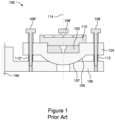
- Figure 1 shows a prior-art die holder 100 as is typically used for a head die.
- the die 102 is fixed by a nut 110 with centre bore in carrier 104.
- the carrier 104 is received in a support 106 that is fixedly connected to the machine frame of the metal wire drawing machine 190.
- the spherical surface 105 of the carrier 104 fits in a fitting spherical cavity 107 of the support 106 and can swivel therein.
- the carrier is held fixed by means of three set screws 108, 108', 108" with a bushing and springs 112, 112".
- the set screws are arranged in a 120° angular configuration.
- the adjustment of this die holder requires at least adjustment of three set screws. Also the fact that set screws or in a 120° angular configuration makes it difficult to adjust the wire in planes perpendicular to one another. It takes quite some skill and experience before an operator can adjust such a die holder.
- the die holder 200 holds the die 202 in carrier 220 by means of a nut 210.
- Figure 2b shows that nut 210 threads into a bushing 226.
- the bushing 226 is held in the carrier 220 by means of circlip-groove fitting 227.
- the bushing 226 can rotate in the carrier 220 by turning the handle 228 as indicated by the arrows in Figure 2a around the centre axis 214.
- the centre axis 214 corresponds to the axis of the bushing 226. This allows to precisely set the rotation of the die 202.
- the carrier 220 is held by two spring actuated pivot hinges 222, 222' mounted opposite to one another in a support 238.
- the support is fixedly connected to the metal wire drawing machine 290.
- the pivot hinges 222, 222' show a pin that is received in respective recesses 224, 224'. This allows to rotate the carrier 220 around the first axis going through the pivot hinges 222, 222' relative to the machine.
- the adjustment means for adjusting the tilting around the first axis is in the form of an inclined wedge surface 236 machined out of the carrier 220.
- the set screw 232 By adjusting the set screw 232 the angle of the centre axis in the first plane - that is the plane perpendicular to the first axis i.e. the axis through the pivot hinges - can be precisely adjusted. This is indicated by the arrows in Figure 2b .
- a large displacement of the set screw 232 results in small angular rotation of the carrier.
- a mechanical spring 234 pushes the carrier 220 back.
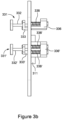
- FIG. 3a and 3b A third preferred embodiment is described in Figure 3a and 3b .
- the die 302 is held in a carrier 320 that consists of a die receiving piece 311 ( Figure 3b ) that is mounted to a first base plate 321.
- a nut 310 holds the die in the die receiving piece 311.
- the centre axis 314 is indicated.
- the first base plate 321 is hingeably connected to a second base plate 321'.
- integral hinges 340 and 340' have been used.
- the hinges 340, 340' form a first axis. Rotation around the first axis is precisely controlled via the first adjustment device 331.
- the first adjustment device 331 consists of a set screw 332 that threads into holder 333.
- the holder 333 is fixedly connected to first base plate 321.
- spring holder 336 is fixedly connected.
- the springs 338 exert a counterforce when the set screw 332 is turned.
- the second base plate 321' is hingeably connected to the support 338 through integral hinges 342 and 342'. Integral hinges 342 and 342' define the second axis.
- the support 338 can be screwed to the wet wire drawing machine 390.
- a second adjustment device 331' allows to rotate the second base plate 321' around the second axis.
- the second adjustment device 331' comprises a set screw 332' threaded in a holder 333' that is fixedly connected to the second plate 321'.
- a spring holder 336' is fixedly connected for exerting a counterforce through springs 338'.
- the whole system of support 338, second base plate 321', first base plate 321 is laser cut out of a single steel plate.
- the hinges 340, 340' and 342, 342' are implemented by partially cutting away material at the first and second axis. So these hinges 340, 340', 342, 342' are integral hinges to the steel plate. These hinges have the advantage that they can be conveniently implemented. However, some after treatment - laser hardening - may be needed to prevent plastic deformation of the hinges, although for the small angular rotations involved, plastic deformation is not expected.
- the die holder of Figures 2a, 2b and even more of Figures 3a , 3b are easier to adjust as they allow to identify easily the planes in which the die is made to rotate. It is much easier for the operator to adjust such a die holder than the prior-art die holders.
- Figure 4 shows a similar embodiment 400 according to Figures 3a and 3b . Therefore the individual parts will not be explained in detail.
- the difference with the Figure 3a , 3b embodiment lays in the use of micromotors 431, 431' as the first and second adjustment device. These micromotors 431, 431' are controlled through controller 492 via line 496 for the second adjustment device 431' and line 498 for the first adjustment device 431.
- the controller 492 receives the desired orientation from a dual axis controller 494.
- the actual position of the drawing die holder can be displayed on the screen 499.
- the ⁇ flat' condition of the die holder i.e.
- the centre axis is perpendicular to the flat of the support 438 is indicated with ' ', the actual condition is indicated with a cross hair ' '. It may well be that straight wire is obtained when the orientation of the die holder is not flat as the bearing axis of the die may not correspond to the centre axis of the die holder.
Landscapes
- Engineering & Computer Science (AREA)
- Mechanical Engineering (AREA)
- Metal Extraction Processes (AREA)
Abstract
An orientable die holder for holding a wire drawing die in a metal wire drawing machine has a carrier in wich the die is recieved. The carrier has a centre axis going through the centre of the die. The cairrier is mounted angulary adjustable by a first pivot means defining a first axis that is perpendicular to the centre axis of the die. In one embodiment the carrier is mounted rotatable around the centre axis. In another emodiment the carrier and the first pivot means are mounted angularly adjustable around a second pivot means defining a second axis. The second axis is in the first plane perpendicular to the first axis. The first plane contains the centre axis. Various advantageous embodiments are described that implement this easily orientable configuration. In one embodiment that orientable die holder has first and second ajdustment devices that allow for a precise adjustment of the bi-axial orientation of the die. The die holder allows for easy adjustment of the centre axis and hence for a straight metal wire.
Description
- The invention relates to a drawing die holder for use in a metal wire drawing machine. The drawing die held in the drawing die holder can be easily oriented.
- The drawing of metal wire is performed by gradually reducing the diameter of the metal wire by drawing the wire through a succession of dies. The dies have an orifice, the diameter of the orifices becoming successively smaller. The dies comprise a nib - made of a cermet or diamond or a diamond compound - that is held in cylindrical casing. The nib has an entrance cone, a bearing and an exit cone. The bearing diameter determines the diameter of the exiting metal wire. The cylindrical casing defines the axis of the drawing die. Note that for small bearing diameters, it becomes difficult to have a perfect alignment between the die axis and the axis of the bearing.
- In order to ease the passage of the wire through the bearing a lubricant must be used. The lubricant can be a dry lubricant such as a fine powdered soap. In that case one speaks of 'dry metal wire drawing'. Typically this is used for large diameter wires - above about one millimeter - and the number of dies is less than fifteen, possibly twelve. Alternatively, the wire can be lubricated with a liquid such as an oil or an emulsion thus called 'wet wire drawing'. This is typically used for smaller wire diameters below about one millimetre. The number of dies may vary from about ten to well over twenty. Although the invention is described for a wet wire drawing machine, the principles can equally well be applied in a dry drawing machine.
- In a wet wire drawing machine the dies are held in 'die holders' in between the capstans that pull the wire through the dies. As there are many dies a collective die holder comb can be used such as described in
CN211990300U . In such combs the dies are loosely held in a cavity. The problem in such combs is that the wire axis is not well aligned with the die axis. - This alignment problem is solved by making an orientable die holder: see e.g.
WO 2019/042937 A1 . A die is held in a holder with spherical mantle held in tight fitting in a cavity. The spherical mantle allows to precisely adjust the orientation of the die and to fix it subsequently. Hence it allows to align the die axis with the wire axis. As such holder is quite bulky and the adjustment requires the frequent release and tensioning of at least three and more frequently four set screws, it can only be used for the last die, also called 'head die'. The head die is that die where the drawn wire exits the machine and is wound on the spool. Moreover the orientation adjustment requires the frequent release and tensioning of those set screws which makes aligning the head die a job requiring skill and patience. - When the wire axis enters the head die, or any intermediate die, that is not in line with the die axis asymmetric residual stresses are induced in the drawn wire. As a result the wire will show `cast' that is: it will assume a non-straight, curved shape when held freely. Cast must be well controlled for 'finished wire products' that are products that will be delivered to customers for further processing. For example spring wires need to be straight for supply to the spring making machine. Also very fine steel wires with a diameter of between 30 and 150 micrometre that are used as substrate wire for diamond coated wire must also be very straight. Brass plated wire used for reinforcement of high pressure hoses on the contrary must have a controlled cast: when a piece of wire is cut from the spool it must assume a circular shape the diameter of which is between limits. In contrast thereto 'monofilament wires' that are brass plated wires with a diameter between 0.30 mm to 0.50 mm for direct use of the wire in the belt of tires must be very straight (
EP 3 027 337 B1 ). - There is also the desire that not only the head die is mounted adjustable but also the dies preceding the head die can be controlled as these also have an impact on the residual stresses inside the drawn wire.
- The main object of the invention is to overcome the problems of existing die holders. A first object is to provide a die holder that can easily be adjusted with a minimum of set screws. A further object is to have a die holder that does not take a lot of space. A further object of the invention is to have a remotely controllable die holder. A still further object of the invention is to provide a wire drawing machine with the die holder or holders.
- According a first aspect of the invention a die holder with the features of claim 1 is described. The die holder is for integration in a metal wire drawing machine. The metal wire drawing machine is preferably a wet wire drawing machine, although the principles of the inventive die holder can also be implemented in a dry drawing machine.
- The die holder comprises a carrier. The carrier receives the drawing die or die hereinafter. The carrier is typically a piece of metal with a bore hole wherein the die tightly fits, seats and is held. The fit can e.g. be ensured by using an elastomeric O-ring. Or a counter nut can be used, although this may take more space and is therefore less preferred. The die must be held because when the machine is stopped, the wire may recoil and the die should not be drawn out of the seat of the carrier.
- The axis of the bore hole of the carrier is the centre axis of the carrier. The centre axis of the carrier goes through, comprises the centre point of the bearing of the die hereinafter called 'the centre of the die'. Note that the axis of the bearing does not need to coincide with this centre axis. Indeed, there may be a deviation between the axis of the bearing in the nib and the axis of the die holder, in particular for very small diameter dies. But these deviations can be compensated by the die holder as will become clear later on.
- The carrier is mounted angularly adjustable relative to the metal wire drawing machine around a first axis with a first pivot means. The metal wire drawing machine is the fixed reference frame. The first axis is oriented perpendicular to the centre axis. In this way the centre axis can be inclined, tilted, pivoted around the centre of the bearing of the die i.e. the centre axis of the carrier rotates in a single plane that is called the first plane. The first plane is thus perpendicular to the first axis and contains the centre axis.
- In a first preferred embodiment, the carrier is mounted rotatable around the centre axis of the carrier. This means that if the die is held in the carrier, the die can rotate with the carrier around the centre axis. In this way the orientation of the axis of the bearing - that may deviate from the centre axis - can be adjusted over all space angles by the combination of tilting around the first axis and turning of the die carrier.
- To align the bearing axis with the wire, one puts the plane of the carrier - that is the perpendicular plane to the centre axis - about perpendicular to the wire. After drawing the wire through the die with an inch movement, the wire will follow the orientation of the bearing. By cutting the wire so that a short tail of the wire remains, one may find the true direction of the bearing. Firstly the carrier is rotated until the tail is in the first plane perpendicular to the first axis. Secondly, the carrier is angularly adjusted by pivoting the carrier around the first axis, in the direction opposite of the tail direction. The wire will now come straight out of the die.
- The advantage is that only two adjustments must be made to orient the wire: rotation of the die around the centre axis and tilting around the first axis.
- According a second more preferred embodiment, both the carrier and the first pivot means are mounted angularly adjustable around a second axis with a second pivot means. The second axis is in the first plane. A technical mind will readily understand that by this mounting the centre axis can be oriented in any direction desired by adjusting two angles.
- The rotatable mount of the carrier around the centre axis is thus no longer necessary i.e. is dispensable although it still may offer a third degree of adjustment.
- In a third preferred embodiment the carrier comprises a die receiving piece that is mounted to a first base plate. This first base plate is hingeably connected to a second base plate through the first pivot means. `Hingeably' in the current context means: pivotable, rotatable, tiltable by means of a hinge. So the first base plate can adjustably rotated, tilted, pivoted relative to the second base plate. The second base plate on its turn is hingeably connected to a support through the second pivot means.
- The support is fixedly connected to the metal wire drawing machine. The centre axis is orientable relative to the metal wire drawing machines. The available space angle for adjustment is around the perpendicular to the support and within a square pyramid of plus or minus 30°, or 20° or even 10° may suffice, in both directions that is: perpendicular to first and second axis.
- Adjustment of the tilting of first and second axis is by means of a first and second adjustment device. The adjustment device must allow for small changes in angle and at the same time be robust in order to withstand the forces exerted on it during drawing.
- The first and/or second adjustment device can be implemented in a number of ways. A non limiting list is:
- By means of a simple set screw, or
- A set screw with a counter spring may be needed in order to push the first and/or second base plate against the set screw,
- Alternatively a set screw with ball joint can be used to avoid to having a counter spring, or
- A set screw with a counter screw or counter nut can be used, or
- Alternatively adjustment can be done by means of a wedge type adjustment device, or
- By means of an actuator. Within the context of this application with 'actuator' is meant any device that can generate controlled motion by means of electrical, pneumatic or hydraulic power. `Controlled' means that there is a feedback loop to ensure correct positioning of the actuator end. Examples are piezo electric actuators, micromotors, servo motors or the like..
- The first and second pivot means can be implemented in a number of ways. A non-limiting list is:
- Mechanical hinges e.g. a butt hinge, or a ball bearing hinge, or
- Integral hinges. Within the context of this application 'integral hinges' are hinges thar are integral to the two parts that hinge to one another. Integral hinges are made by providing a local weakening that allows controlled bending at the weakened spot. Integral hinges may - depending on the material - allow larger or smaller pivot angels. Integral hinges do offer the advantage that they provide a spring back, a counterforce that resists the bending at the hinge. In this way a counter spring may be obsoleted in the case of simple set screw adjustment.
- Alternatively blade springs can be used to provide a pivot means. Disadvantage of this is that the pivot point must be calculated and may vary for too high pivot angles. Also the forces that can be taken by blade springs are lower than that of an integral spring;
- Also pivot hinges may be used. Pivot hinges comprise a conical hole at the one part of the hinge wherein a pin is pushed and turns that is connected to the other part. In the die holder two opposite pushing pivot hinges can be conveniently used to form one pivot means.
- Materials used for the die holder are preferably metals like machine steel. Alternatively high performance polymer materials like poly oxy methylene or poly amide can be used when the forces acting on the die holder are not excessive that is for the drawing of very fine wires. The drawing die holder can be machined out of the polymer material or even 3D printed directly into shape and form as desired.
- In a further preferred embodiment a pointer means for controlled adjustment of the first and second adjustment means can be used. This can take the form of a longer pin, like a nail or pin, mounted perpendicular to the carrier or to the first base plate of the die holder. The pointer may point to a two dimensional surface to accurately determine the position of the pointer. Alternatively a mirror spot can be provide on the carrier on which a laser beam reflects. The laser beam is fixedly connected to the machine. The reflection can be caught on a screen for precise adjustment of the die holder.
- In a further preferred embodiment, the first and/or the second adjustment device is/are electrically driven and can be remotely controlled by a dual axis controller. The remote control can be wired or wire less. In this way fast and accurate adjustment of the die holder becomes possible without the operator having to put his hands on the machine.
- According a second aspect of the invention, a wire drawing machine is claimed. Such wire drawing machines are know per sé. They can be of the dry drawing type or the wet wire drawing type. The latter is more preferred. Such a machine generally accommodates between ten and thirty dies and one head die. Characteristic about the wire drawing machine is that at least one of the dies is held in a die holder as previously described.
- In a preferable embodiment the at least one of the die holders comprises a die holder for a head die. Indeed, the head die has the most control on the cast of the drawn wire. Preceding dies have also an influence on the wire straightness, but to a lesser extent.
- In another preferred embodiment the head die and one up to five dies preceding the head die are held in a die holder as described above. Terms like 'preceding' and 'before' or `after' and 'subsequent' are relative to the drawing direction of the wire: dies with a larger diameter are 'before' or 'preceding' a certain die, dies with a smaller diameter are 'subsequent' to the die under consideration.
- The die holder offers many advantages over the prior art die holders:
- They allow for easy adjustment of the central axis: only two set screws must be adjusted;
- The set screws must not be blocked,
- The die holder can be made compact and can be used - not only at the headdie - but also on dies preceding the headdie.
- The die holder holds the dies fixed: compared to prior art die holder 'combs', the dies are held in a fixed, adjustable position without play.
- In what follows a more detailed description of certain embodiments will be given.
-
-
Figure 1 shows a prior-art die holder, that can be replaced with the invention die holder. -
Figure 2a shows a first realisation of the die holder in top view -
Figure 2b shows the section AA' as perFigure 2a of the first realisation of the die holder -
Figure 3a shows more preferred reduction to practise of the invention die holder in top view. -
Figure 3b shows a side view of theFigure 3a , along the line BB'. -
Figure 4 shows a schematic embodiment of an actuator driven die holder with the dual axis controller. - Like items will be numbered with equal unit and tens digit, the hundred digit referring to the number of the figure.
-
Figure 1 shows a prior-art die holder 100 as is typically used for a head die. Thedie 102 is fixed by anut 110 with centre bore incarrier 104. Thecarrier 104 is received in asupport 106 that is fixedly connected to the machine frame of the metalwire drawing machine 190. Thespherical surface 105 of thecarrier 104 fits in a fittingspherical cavity 107 of thesupport 106 and can swivel therein. The carrier is held fixed by means of three setscrews - In a first preferred embodiment of the inventive die holder of which a top view is shown in
Figure 2a , thedie holder 200 holds the die 202 incarrier 220 by means of anut 210.Figure 2b shows thatnut 210 threads into abushing 226. Thebushing 226 is held in thecarrier 220 by means of circlip-groove fitting 227. Thebushing 226 can rotate in thecarrier 220 by turning thehandle 228 as indicated by the arrows inFigure 2a around thecentre axis 214. Thecentre axis 214 corresponds to the axis of thebushing 226. This allows to precisely set the rotation of thedie 202. - The
carrier 220 is held by two spring actuated pivot hinges 222, 222' mounted opposite to one another in asupport 238. The support is fixedly connected to the metalwire drawing machine 290. The pivot hinges 222, 222' show a pin that is received inrespective recesses 224, 224'. This allows to rotate thecarrier 220 around the first axis going through the pivot hinges 222, 222' relative to the machine. - The adjustment means for adjusting the tilting around the first axis is in the form of an
inclined wedge surface 236 machined out of thecarrier 220. By adjusting theset screw 232 the angle of the centre axis in the first plane - that is the plane perpendicular to the first axis i.e. the axis through the pivot hinges - can be precisely adjusted. This is indicated by the arrows inFigure 2b . A large displacement of theset screw 232 results in small angular rotation of the carrier. In order to hold thecarrier 220 against theinclined wedge surface 236, amechanical spring 234 pushes thecarrier 220 back. - A third preferred embodiment is described in
Figure 3a and3b . Again thedie 302 is held in acarrier 320 that consists of a die receiving piece 311 (Figure 3b ) that is mounted to afirst base plate 321. Like before anut 310 holds the die in thedie receiving piece 311. Thecentre axis 314 is indicated. - The
first base plate 321 is hingeably connected to a second base plate 321'. In this embodiment integral hinges 340 and 340' have been used. In this manner thehinges 340, 340' form a first axis. Rotation around the first axis is precisely controlled via thefirst adjustment device 331. As shown inFigure 3b , thefirst adjustment device 331 consists of aset screw 332 that threads intoholder 333. Theholder 333 is fixedly connected tofirst base plate 321. At the opposite side offirst plate 321,spring holder 336 is fixedly connected. Thesprings 338 exert a counterforce when theset screw 332 is turned. - In a similar way the second base plate 321' is hingeably connected to the
support 338 throughintegral hinges 342 and 342'. Integral hinges 342 and 342' define the second axis. Thesupport 338 can be screwed to the wetwire drawing machine 390. Likewise a second adjustment device 331' allows to rotate the second base plate 321' around the second axis. Again the second adjustment device 331' comprises a set screw 332' threaded in a holder 333' that is fixedly connected to the second plate 321'. At the opposite side of the latter, a spring holder 336' is fixedly connected for exerting a counterforce through springs 338'. - The whole system of
support 338, second base plate 321',first base plate 321 is laser cut out of a single steel plate. The hinges 340, 340' and 342, 342' are implemented by partially cutting away material at the first and second axis. So thesehinges - The die holder of
Figures 2a, 2b and even more ofFigures 3a ,3b are easier to adjust as they allow to identify easily the planes in which the die is made to rotate. It is much easier for the operator to adjust such a die holder than the prior-art die holders. -
Figure 4 shows asimilar embodiment 400 according toFigures 3a and3b . Therefore the individual parts will not be explained in detail. The difference with theFigure 3a ,3b embodiment lays in the use ofmicromotors 431, 431' as the first and second adjustment device. Thesemicromotors 431, 431' are controlled throughcontroller 492 vialine 496 for the second adjustment device 431' andline 498 for thefirst adjustment device 431. Thecontroller 492 receives the desired orientation from adual axis controller 494. The actual position of the drawing die holder can be displayed on thescreen 499. The `flat' condition of the die holder i.e. the centre axis is perpendicular to the flat of thesupport 438 is indicated with '', the actual condition is indicated with a cross hair ' '. It may well be that straight wire is obtained when the orientation of the die holder is not flat as the bearing axis of the die may not correspond to the centre axis of the die holder.
- By these inventions the adjustment of the die holders becomes much more convenient for the operator and having a number of adapted die holders upstream from the head die results in straight wire.
Claims (12)
- A die holder, for holding a die in a metal wire drawing machine, said die holder comprising a carrier for receiving the die, said carrier having a centre axis comprising the centre of the die,
characterized in that
said carrier is mounted angularly adjustable relative to the metal wire drawing machine, around a first axis with a first pivot means, said first axis being perpendicular to said centre axis. - The die holder according to claim 1 wherein said carrier is mounted rotatable around said centre axis.
- The die holder according to claim 1 or 2 wherein said carrier and said first pivot means are mounted angularly adjustable around a second axis with a second pivot means, wherein said second axis is in a first plane perpendicular to said first axis, said first plane containing said centre axis.
- The die holder according to any one of claims 1 to 3 wherein said carrier comprises a die receiving piece mounted to a first base plate, said first base plate being hingeably connected to a second base plate through said first pivot means, said second base plate being hingeably connected to a support through said second pivot means, said support being fixedly connected to the metal wire drawing machine.
- The die holder according to any one of claims 1 to 4 wherein said carrier is angularly adjustable around said first pivot means by means of a first adjustment device and/or said carrier and said first pivot means is angularly adjustable around said second pivot means by means of a second adjustment device.
- The die holder according to any one of claims 1 to 5 wherein said first and/or said second adjustment device are one out of the group comprising a set screw, a set screw with ball joint, a set screw with counter screw or counter nut, a set screw with counter spring, an adjustable wedge, an actuator.
- The die holder according to any one of claims 1 to 6 wherein said first and/or second pivot means are one out of the group comprising mechanical hinges, integral hinges, blade spring hinges, pivot hinges.
- The die holder according to any one of claims 1 to 7 wherein said carrier is provided with a pointer means for controlled adjustment of the first and second adjustment means.
- The die holder according claim 8 wherein the pointer means is a pin parallel to the centre axis or wherein the pointer means is a mirrored surface means for reflection of a light beam.
- The die holder according to any one of claims 6 to 9 wherein said first and/or said second adjustment device are electrically driven actuators that are remotely controlled by a dual axis controller.
- A wire drawing machine for drawing metal wire, wherein said wire drawing machine holds one or more dies, characterized in that
at least one of said dies being held in a die holder according to any one of claims 1 to 10. - The wire drawing machine according claim 11 wherein the head die and one up to five dies preceding the head die are held in a die holder according to claim any one of claims 1 to 10.
Priority Applications (1)
| Application Number | Priority Date | Filing Date | Title |
|---|---|---|---|
| EP23169119.7A EP4450179A1 (en) | 2023-04-21 | 2023-04-21 | Orientable drawing die holder for wire drawing |
Applications Claiming Priority (1)
| Application Number | Priority Date | Filing Date | Title |
|---|---|---|---|
| EP23169119.7A EP4450179A1 (en) | 2023-04-21 | 2023-04-21 | Orientable drawing die holder for wire drawing |
Publications (1)
| Publication Number | Publication Date |
|---|---|
| EP4450179A1 true EP4450179A1 (en) | 2024-10-23 |
Family
ID=86142953
Family Applications (1)
| Application Number | Title | Priority Date | Filing Date |
|---|---|---|---|
| EP23169119.7A Withdrawn EP4450179A1 (en) | 2023-04-21 | 2023-04-21 | Orientable drawing die holder for wire drawing |
Country Status (1)
| Country | Link |
|---|---|
| EP (1) | EP4450179A1 (en) |
Citations (9)
| Publication number | Priority date | Publication date | Assignee | Title |
|---|---|---|---|---|
| US2526237A (en) * | 1945-06-16 | 1950-10-17 | Johnson Steel & Wire Company I | Adjustable mounting for wire drawing dies |
| GB704278A (en) * | 1951-10-16 | 1954-02-17 | Gen Electric Co Ltd | Improvements in or relating to methods of drawing wire through dies |
| DE1228581B (en) * | 1964-04-04 | 1966-11-17 | Felten & Guilleaume Carlswerk | Holder for a drawing die |
| US3402587A (en) * | 1966-04-05 | 1968-09-24 | Western Electric Co | Wire drawing apparatus |
| JPS5417839U (en) * | 1978-07-14 | 1979-02-05 | ||
| JP4436071B2 (en) * | 2003-05-20 | 2010-03-24 | 田中電子工業株式会社 | Extra fine wire drawing method and drawing device |
| EP3027337B1 (en) | 2013-07-29 | 2018-08-29 | NV Bekaert SA | Straight monofilament for belt ply |
| WO2019042937A1 (en) | 2017-08-28 | 2019-03-07 | Compagnie Generale Des Etablissements Michelin | Wire-drawing device comprising means for orienting a wire-drawing member |
| CN211990300U (en) | 2019-12-27 | 2020-11-24 | 镇江耐丝新型材料有限公司 | Double-mold-structure steel wire drawing mold base |
-
2023
- 2023-04-21 EP EP23169119.7A patent/EP4450179A1/en not_active Withdrawn
Patent Citations (9)
| Publication number | Priority date | Publication date | Assignee | Title |
|---|---|---|---|---|
| US2526237A (en) * | 1945-06-16 | 1950-10-17 | Johnson Steel & Wire Company I | Adjustable mounting for wire drawing dies |
| GB704278A (en) * | 1951-10-16 | 1954-02-17 | Gen Electric Co Ltd | Improvements in or relating to methods of drawing wire through dies |
| DE1228581B (en) * | 1964-04-04 | 1966-11-17 | Felten & Guilleaume Carlswerk | Holder for a drawing die |
| US3402587A (en) * | 1966-04-05 | 1968-09-24 | Western Electric Co | Wire drawing apparatus |
| JPS5417839U (en) * | 1978-07-14 | 1979-02-05 | ||
| JP4436071B2 (en) * | 2003-05-20 | 2010-03-24 | 田中電子工業株式会社 | Extra fine wire drawing method and drawing device |
| EP3027337B1 (en) | 2013-07-29 | 2018-08-29 | NV Bekaert SA | Straight monofilament for belt ply |
| WO2019042937A1 (en) | 2017-08-28 | 2019-03-07 | Compagnie Generale Des Etablissements Michelin | Wire-drawing device comprising means for orienting a wire-drawing member |
| CN211990300U (en) | 2019-12-27 | 2020-11-24 | 镇江耐丝新型材料有限公司 | Double-mold-structure steel wire drawing mold base |
Similar Documents
| Publication | Publication Date | Title |
|---|---|---|
| US4788847A (en) | Rod bending apparatus | |
| US6024319A (en) | Tension control apparatus | |
| US11426952B2 (en) | Lay-up head | |
| EP3649069A1 (en) | Winding device with support roller and pressing force-regulating device, and thread processing machine | |
| JPH0716830B2 (en) | A device that circulates the electrodes of a spark corrosion cutter around the wheel. | |
| JP7174035B2 (en) | roller burnishing tool | |
| US20100203810A1 (en) | Sharpening system for scissors with complex curved blades | |
| JP2004516951A (en) | Electrode guide for spark erosion machine and method for spark erosion of workpiece | |
| US4825678A (en) | Three-dimensional bending apparatus | |
| US10919319B2 (en) | Printing and drying installation and printing and drying method | |
| US5214260A (en) | Electrical discharge machine wire electrode guiding device | |
| JPS6174794A (en) | Working head of laser working device | |
| CN113710445B (en) | Wire granulator for granulating wire of material and method for adjusting cutting gap of wire of material | |
| EP0159383A1 (en) | Machine for grinding toric surfaces of optical lenses | |
| JPS61113849A (en) | Yarn texurizing jet apparatus | |
| CN106044358A (en) | Devices for guiding and conveying wire-shaped or strand-shaped products | |
| US4945200A (en) | Electrical discharge machine apparatus moving wire electrode guide assembly | |
| WO2000050204A1 (en) | Tool unit with a cutting head | |
| US4994643A (en) | Electrical discharge machine apparatus tilted current pickup | |
| JPH08506758A (en) | Coating equipment with adjustable blade | |
| US20200225136A1 (en) | Thread guide wear testing machine and thread guide wear testing method | |
| US4913084A (en) | Apparatus useful in devices for controlling the thickness of coating applied to a substrate | |
| US5730017A (en) | Cutter holder | |
| US4754576A (en) | Optical fibre grinder | |
| US20240058919A1 (en) | Method and Device for Finely Machining Axicons, Fine Machining Device Suitable for this Purpose,and Use Thereof |
Legal Events
| Date | Code | Title | Description |
|---|---|---|---|
| PUAI | Public reference made under article 153(3) epc to a published international application that has entered the european phase |
Free format text: ORIGINAL CODE: 0009012 |
|
| STAA | Information on the status of an ep patent application or granted ep patent |
Free format text: STATUS: THE APPLICATION HAS BEEN PUBLISHED |
|
| AK | Designated contracting states |
Kind code of ref document: A1 Designated state(s): AL AT BE BG CH CY CZ DE DK EE ES FI FR GB GR HR HU IE IS IT LI LT LU LV MC ME MK MT NL NO PL PT RO RS SE SI SK SM TR |
|
| STAA | Information on the status of an ep patent application or granted ep patent |
Free format text: STATUS: THE APPLICATION IS DEEMED TO BE WITHDRAWN |
|
| 18D | Application deemed to be withdrawn |
Effective date: 20250424 |