EP4450009A2 - Elektrochirurgischer stift - Google Patents
Elektrochirurgischer stift Download PDFInfo
- Publication number
- EP4450009A2 EP4450009A2 EP24191357.3A EP24191357A EP4450009A2 EP 4450009 A2 EP4450009 A2 EP 4450009A2 EP 24191357 A EP24191357 A EP 24191357A EP 4450009 A2 EP4450009 A2 EP 4450009A2
- Authority
- EP
- European Patent Office
- Prior art keywords
- tube
- section
- electrode
- suction tip
- proximal
- Prior art date
- Legal status (The legal status is an assumption and is not a legal conclusion. Google has not performed a legal analysis and makes no representation as to the accuracy of the status listed.)
- Granted
Links
Images



Classifications
-
- A—HUMAN NECESSITIES
- A61—MEDICAL OR VETERINARY SCIENCE; HYGIENE
- A61B—DIAGNOSIS; SURGERY; IDENTIFICATION
- A61B18/00—Surgical instruments, devices or methods for transferring non-mechanical forms of energy to or from the body
- A61B18/04—Surgical instruments, devices or methods for transferring non-mechanical forms of energy to or from the body by heating
- A61B18/12—Surgical instruments, devices or methods for transferring non-mechanical forms of energy to or from the body by heating by passing a current through the tissue to be heated, e.g. high-frequency current
- A61B18/14—Probes or electrodes therefor
- A61B18/1402—Probes for open surgery
-
- A—HUMAN NECESSITIES
- A61—MEDICAL OR VETERINARY SCIENCE; HYGIENE
- A61B—DIAGNOSIS; SURGERY; IDENTIFICATION
- A61B18/00—Surgical instruments, devices or methods for transferring non-mechanical forms of energy to or from the body
- A61B2018/00571—Surgical instruments, devices or methods for transferring non-mechanical forms of energy to or from the body for achieving a particular surgical effect
- A61B2018/00589—Coagulation
-
- A—HUMAN NECESSITIES
- A61—MEDICAL OR VETERINARY SCIENCE; HYGIENE
- A61B—DIAGNOSIS; SURGERY; IDENTIFICATION
- A61B18/00—Surgical instruments, devices or methods for transferring non-mechanical forms of energy to or from the body
- A61B2018/00571—Surgical instruments, devices or methods for transferring non-mechanical forms of energy to or from the body for achieving a particular surgical effect
- A61B2018/00601—Cutting
-
- A—HUMAN NECESSITIES
- A61—MEDICAL OR VETERINARY SCIENCE; HYGIENE
- A61B—DIAGNOSIS; SURGERY; IDENTIFICATION
- A61B18/00—Surgical instruments, devices or methods for transferring non-mechanical forms of energy to or from the body
- A61B2018/00571—Surgical instruments, devices or methods for transferring non-mechanical forms of energy to or from the body for achieving a particular surgical effect
- A61B2018/00607—Coagulation and cutting with the same instrument
-
- A—HUMAN NECESSITIES
- A61—MEDICAL OR VETERINARY SCIENCE; HYGIENE
- A61B—DIAGNOSIS; SURGERY; IDENTIFICATION
- A61B2217/00—General characteristics of surgical instruments
- A61B2217/002—Auxiliary appliance
- A61B2217/005—Auxiliary appliance with suction drainage system
-
- A—HUMAN NECESSITIES
- A61—MEDICAL OR VETERINARY SCIENCE; HYGIENE
- A61B—DIAGNOSIS; SURGERY; IDENTIFICATION
- A61B2218/00—Details of surgical instruments, devices or methods for transferring non-mechanical forms of energy to or from the body
- A61B2218/001—Details of surgical instruments, devices or methods for transferring non-mechanical forms of energy to or from the body having means for irrigation and/or aspiration of substances to and/or from the surgical site
- A61B2218/007—Aspiration
-
- A—HUMAN NECESSITIES
- A61—MEDICAL OR VETERINARY SCIENCE; HYGIENE
- A61B—DIAGNOSIS; SURGERY; IDENTIFICATION
- A61B2218/00—Details of surgical instruments, devices or methods for transferring non-mechanical forms of energy to or from the body
- A61B2218/001—Details of surgical instruments, devices or methods for transferring non-mechanical forms of energy to or from the body having means for irrigation and/or aspiration of substances to and/or from the surgical site
- A61B2218/007—Aspiration
- A61B2218/008—Aspiration for smoke evacuation
Definitions
- the present invention relates to an electrosurgical pencil for electrosurgical cutting or coagulation of tissue.
- the pencil comprises an elongated body, an exposed electrode, and telescoping means for changing a distance between the electrode and the elongated body.
- Electro-Surgical (ES) pencils are used in surgery, typically for cutting tissue and/or for coagulating blood.
- An ES pencil usually comprises a hand-piece into which electrodes of many different shapes and sizes may be placed.
- the electrode is supplied with a high frequency, typically Radio Frequency (RF), alternating current signal by an RF source.
- RF Radio Frequency
- the RF source is typically called the Electro-Surgical Unit or ESU.
- the electrode By varying the voltage and/or the frequency of the RF signal supplied by the ESU, the electrode can be used in different modes. Two common modes are a cutting mode and a coagulating mode.
- An improved type of pencil includes a telescoping function by which the length of the pencil can be changed without necessitating replacement of the electrode.
- Smoke generation during ES may reduce visibility and it may be unpleasant or even unhealthy for the surgeon and the surgical staff. Therefore smoke vacuation shrouds can be attached to an ES pencil for evacuating smoke close to the electrode.
- an electro-surgical pencil comprising:
- the position of the electrode is adjustable relative to the housing and the surgeon can match the length of the pencil to a specific purpose. This is done by moving the tube into the housing to thereby create a short configuration, or by moving the tube out of the housing and thereby create a long configuration of the pencil.
- the surgeon may adapt the position of the suction tip to a specific electrode and balance between the need for smoke evacuation and the need for unhindered view of the electrode tip where the cutting takes place. This is done by moving the suction tip away from the tube and housing to create a configuration where a larger portion of the electrode is covered and smoke evacuation takes place close to the tip of the electrode, or by moving the suction tip towards the tube and housing to create a configuration where a lesser portion of the electrode is covered thereby exposing the electrode for better visibility.
- the surgeon may set the position of the suction tip independently on the positioning of the tube relative to the housing. In that way, the surgeon may change the length of the pencil by adjusting the position of the tube and maintain the position of the suction tip relative to the electrode. This makes the use of the pencil efficient and prevents the need for repeated adjustment of the suction tip each time the length is adjusted.
- the electrode extends axially from the proximal extension opening and the suction tip forms a further extension of the suction passage, it provides efficient smoke removal around the electrode.
- the electrode may be fixed to a socket which is inside the extension of the main suction passage formed by the tube and thereby follow the movement of the tube relative to the housing.
- the suction tip may be slidable along an inner surface inside the tube or along an outer surface outside the tube. By sliding the suction tip over the outer surface of the tube, the cross section of the suction tip may be larger, and the flow conditions in the suction passage can be improved.
- the suction tip is slidable on an outer surface of the tube and receivable in a recess in the housing to thereby provide good suction properties and a particularly short pencil in the short configuration.
- larger or smaller cross section herein refers to the area of a cross section perpendicular to the axial direction of the pencil.
- the axial direction is the direction from the proximal opening to the distal opening along the centre of the pencil. If the cross section has a circular shape, the diameter of that circular shape may express the size of the cross section.
- the suction tip When the tube is telescopically moved to the short configuration, the suction tip becomes located close to the housing.
- the suction tip may particularly be configured to be slidable partly into the housing. It may thus be configured to be slidable along an inner surface of the housing, e.g. an inner surface of the suction passage, or an inner surface of a recess formed in the housing at the proximal opening.
- the housing may include a collar which enhances the grip by enlarging the radial dimension of the housing.
- the housing comprises a main body forming the suction passage and the proximal opening, and a collar formed about the proximal opening.
- the collar may be operable, e.g. by rotation, for controlling movability of the tube relative to the housing, e.g. by reducing or increasing the friction against movement of the tube in the housing.
- the suction tip may be receivable into a space within the collar or between the collar and the main body of the housing whereby the collar forms the above mentioned inner surface of the housing against which the suction tip is slidable.
- the collar may provide two functions. It increases the cross section of the housing locally and thus improves the ergonomic characteristics of the pencil, and it facilitates locking and unlocking of the tube relative to the housing.
- the tip of the suction tip can be positioned very close to the location where the user grips the pencil when gripping the collar. Accordingly, also the electrode tip may come very close to the position where the surgeon holds the pencil.
- the short distance between the gripping location and the electrode tip increases significantly the ability to correctly manoeuvre the electrode, and the combination between the collar and the recess which receives the suction tip therefore provides very good ergonomic properties of the pencil.
- the length of the pencil can be reduced not only by the telescopic movement of the tube into the housing but also by the movement of the suction tip into the housing, and a pencil with suction tip and movable from a relatively short configuration to a relatively long configuration can be obtained.
- the tube may form a radially recessed portion and the suction tip may extend into the recessed portion.
- the recessed portion may particularly be formed between two sections of the tube which is not recessed such that the suction tip can be confined in the recessed portion. In that way, the recessed portion may limit axial movement of the suction tip relative to the tube.
- the recess may extend circumferentially and completely about the outer periphery of the tube, or the recess may form one or more discrete depressions in the outer surface of the tube.
- the suction tip may comprise a widened distal section axially offset from a narrow proximal section, the widened distal section may have a larger cross section than the tube and the narrow proximal section may have a smaller cross section than the tube. In that way, the widened distal section may slide on an outer surface of the tube while the narrow proximal section may increase the flow speed of the smoke evacuation and provide better visibility to the tip of the electrode where the cutting takes place. Between the wide section and the narrow section, the suction tip may form a transition section providing gradually reduced cross section from the widened distal section to the narrow proximal section.
- the widened distal section may have a cross section being at least twice the cross section of the narrow proximal section, e.g. three or four or five times the cross section of the narrow proximal section.
- the tube and/or the suction tip may particularly have a circular cross section such that the suction tip can be rotated about the outer surface the tube.
- the proximal opening may also have a circular cross section such that the tube can be rotated in the proximal opening.
- the pencil may comprise a switching structure including a switch for controlling application of an electrosurgical RF signal to the electrode.
- a switch for controlling application of an electrosurgical RF signal to the electrode.
- the surgeon will typically hold the pencil at a position where the switch can be operated while holding the housing in a firm grip.
- it may be arranged that the distance along the axial direction between the tube and the switch is smaller than the largest dimension of the housing in the cross section perpendicular to the axial direction.
- the switching structure may particularly be isolated from the suction passage.
- the switching structure is housed in a first compartment inside the housing and the suction passage is formed by a second and completely separate compartment inside the housing. This prevents ingress of tissue and fluid to impare the functioning of the switch.
- the suction tip may comprise a threaded connection to the tube such that movement of the suction tip relative to the tube can be effected by rotation of the suction tip relative to the tube.
- the suction tip and tube comprises coorporating sliding surface forming a linear joint which enables linear sliding of the suction tip relative to the tube but prevents rotation of the suction tip relative to the tube.
- the invention provides a method of configuring an electro-surgical pencil which comprises:
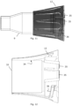
- Fig. 1 illustrates an electro-surgical pencil 1 with a housing 2.
- the pencil includes a tube 3 being telescopically movable in a main suction passage such that the length of the pencil can be varied forwardly and rearwardly as illustrated by the arrow 4 to thereby define the long configuration illustrated in Fig. 1 and the short configuration illustrated in Fig. 2 .
- the pencil comprises an electrode 5 which is releasably attached to the proximal end of the tube.
- the electrode is connected to an RF generator and conducts an ES signal for cutting and/or coagulating tissue.
- the signal is controlled by the switches 6, 7, one switch providing a signal suitable for cutting and one switch providing a signal suitable for coagulation.
- the illustrated electrode and pencil are for monopolar cutting but it could also be for bipolar cutting.
- the pencil defines an axially extending main suction passage shown in details in the later drawings.
- the suction passage extends from a proximal opening to a distal opening.
- a suction tube 8 connects the pencil to a suction pump for establishing suction and thus smoke removal.
- the pencil comprises a suction tip 9 attached to the proximal end of the tube and forming a further extension of the suction passage.
- the tip is movable forward and rearward relative to the tube as illustrated by the arrow 10 and being configured for telescoping movement relative to the tube.
- the suction passage can be extended relative to the electrode to cover a larger or lesser portion of the electrode and the surgeon can thereby adjust the pencil to balance between the configuration where very good suction is obtained by a suction tip close to the electrode tip and the configuration where very good visibility can be obtained by a suction tip at a distance from the electrode tip.
- the tip may remain in a fixed position relative to the tube since it is attached to the tube and not to the housing.
- the housing 2 comprises a main body 11 and a collar 12.
- the collar 12 is located at the proximal end of the housing and is rotational about the main body.
- the collar is configured to increase or decrease friction between an outer surface of the tube and the inner surface of the collar depending on the angular position of the collar relative to the main body and it thus functions to lock or unlock the tube in the suction passage.
- Fig. 5 illustrates an exploded perspective view of the pencil.
- the main body 11 is split into a lower main body part 13 and an upper main body part 14.
- the lower main body part 13 forms an axially extending main suction passage from a proximal opening 15 to a distal opening 16.
- the suction tube 8 is connectable to the distal end.
- the upper main body part 14 houses electronic components completely separated from the suction passage, i.e. wiring and contacts.
- contact elements 17, 18 are located below the switches 6, 7 and connect the RF signal to the electrode 5.
- the RF signal is transferred to a first sliding connector formed inside the suction passage, and by sliding connection to a second sliding connector 19 on an outer surface of the tube 3.
- the RF signal is further transferred to the electrode connector 20.
- Fig. 6 illustrates a cross section of the main body 11 including the main suction passage 21 extending between the proximal and distal openings 15, 16.
- the tube 8 is telescopically movable in the main suction passage and extends outwards from the proximal opening 15.
- Fig. 7 illustrates a cross section of the tube 3 including the inner conduit 22 extending between a distal extension opening 23 and a proximal extension opening 24.
- the tube forms an extension of the main suction passage 21 from the proximal opening 15 to the proximal extension opening 24 in the proximal end of the tube.
- the second sliding connector 19 on the outer surface of the tube enters into the conduit 22 through an opening at the position 25 and extends towards the electrode connector 20.
- Fig. 8 illustrates the suction tip 9 forming a further extension 27 of the suction passage.
- the suction tip is configured for telescoping movement relative to the tube 3 to cover a larger or lesser portion of the electrode.
- the suction tip forms a widened distal section 28 which has a larger cross section than the tube and the inner surface of the widened section 28 can therefore slide on the outer surface of the tube.
- the suction tip further forms a narrow proximal section 29 with a smaller cross section than the tube. Between the widened and the narrow section, the suction tip forms a transition section 30 in which the cross section is gradually reduced from the widened distal section to the narrow proximal section.
- the cross sections of the sections are circular, and the diameter is different.
- the diameter of the narrow proximal section may be in the range of 65-95 percent of the diameter of the widened section.
- Fig. 9 illustrates an enlarged view of the distal end of the suction tip
- Fig. 10 illustrates an enlarged view of the proximal end of the tube 3.
- the tube forms a radially recessed portion 31 extending circumferentially and completely around the tube.
- the distal end of the suction tip is received in the recessed portion. More specifically, the distal portion of the suction tip forms a radial inward projection 32 which slides on the outer surface of the tube 3 in the recessed portion 31.
- the recessed portion thereby limits the movability of the suction tip relative to the tube.
- Fig. 11 illustrates the proximal end of the pencil in the collapsed configuration.
- the suction tip 9 is partly received into the housing - more specifically into the space or recess below the collar 12 of the housing.
- Fig. 12 illustrates a cross section of the collar 12.
- the collar forms part of the housing and forms a proximal termination 33 thereof.
- the collar forms an inner sliding surface 34 on which the outer surface of the suction tip 9 slides when the suction tip is received in the recess of the collar.
- the collar forms inner projections 35, and a thread portion 36.
- the inner projections 35 extend into the main suction passage and interact with a cam surface of the main body of the housing by rotation. In one position of the collar, the inner projections are released, and in another position of the collar, the projection is pressed radially inwardly by the cam of the housing. By the radial inwards deflection, the inner projections 35 are pressed against the tube 3 and therefore limits movement of the tube in the main suction passage.
- the collar thereby forms a fixing structure for fixing the position of the tube relative to the housing.
- Fig. 13 illustrates further details of the inner projections 35, and particularly illustrates that they extend into the suction passage and forms an edge capable of maintaining the position of the tube in the suction passage.
- Fig. 13 also illustrates that the projections 35 terminate in bended sections forming ridges or edges 37 which can be pressed into the outer surface of the tube.
Landscapes
- Health & Medical Sciences (AREA)
- Surgery (AREA)
- Engineering & Computer Science (AREA)
- Life Sciences & Earth Sciences (AREA)
- Biomedical Technology (AREA)
- Otolaryngology (AREA)
- Nuclear Medicine, Radiotherapy & Molecular Imaging (AREA)
- Plasma & Fusion (AREA)
- Physics & Mathematics (AREA)
- Heart & Thoracic Surgery (AREA)
- Medical Informatics (AREA)
- Molecular Biology (AREA)
- Animal Behavior & Ethology (AREA)
- General Health & Medical Sciences (AREA)
- Public Health (AREA)
- Veterinary Medicine (AREA)
- Surgical Instruments (AREA)
Priority Applications (1)
| Application Number | Priority Date | Filing Date | Title |
|---|---|---|---|
| EP25207099.0A EP4652946A3 (de) | 2016-04-14 | 2017-04-04 | Elektrochirurgischer stift |
Applications Claiming Priority (3)
| Application Number | Priority Date | Filing Date | Title |
|---|---|---|---|
| EP16165395 | 2016-04-14 | ||
| PCT/EP2017/057989 WO2017178286A1 (en) | 2016-04-14 | 2017-04-04 | An electrosurgical pencil |
| EP17715702.1A EP3442455B1 (de) | 2016-04-14 | 2017-04-04 | Elektrochirurgischer stift |
Related Parent Applications (1)
| Application Number | Title | Priority Date | Filing Date |
|---|---|---|---|
| EP17715702.1A Division EP3442455B1 (de) | 2016-04-14 | 2017-04-04 | Elektrochirurgischer stift |
Related Child Applications (1)
| Application Number | Title | Priority Date | Filing Date |
|---|---|---|---|
| EP25207099.0A Division EP4652946A3 (de) | 2016-04-14 | 2017-04-04 | Elektrochirurgischer stift |
Publications (3)
| Publication Number | Publication Date |
|---|---|
| EP4450009A2 true EP4450009A2 (de) | 2024-10-23 |
| EP4450009A3 EP4450009A3 (de) | 2025-01-22 |
| EP4450009B1 EP4450009B1 (de) | 2025-10-08 |
Family
ID=55754212
Family Applications (3)
| Application Number | Title | Priority Date | Filing Date |
|---|---|---|---|
| EP25207099.0A Pending EP4652946A3 (de) | 2016-04-14 | 2017-04-04 | Elektrochirurgischer stift |
| EP24191357.3A Active EP4450009B1 (de) | 2016-04-14 | 2017-04-04 | Elektrochirurgischer stift |
| EP17715702.1A Active EP3442455B1 (de) | 2016-04-14 | 2017-04-04 | Elektrochirurgischer stift |
Family Applications Before (1)
| Application Number | Title | Priority Date | Filing Date |
|---|---|---|---|
| EP25207099.0A Pending EP4652946A3 (de) | 2016-04-14 | 2017-04-04 | Elektrochirurgischer stift |
Family Applications After (1)
| Application Number | Title | Priority Date | Filing Date |
|---|---|---|---|
| EP17715702.1A Active EP3442455B1 (de) | 2016-04-14 | 2017-04-04 | Elektrochirurgischer stift |
Country Status (3)
| Country | Link |
|---|---|
| US (3) | US11937865B2 (de) |
| EP (3) | EP4652946A3 (de) |
| WO (1) | WO2017178286A1 (de) |
Families Citing this family (6)
| Publication number | Priority date | Publication date | Assignee | Title |
|---|---|---|---|---|
| CN108742833B (zh) * | 2018-08-13 | 2024-02-13 | 浙江迈德实达医疗科技有限公司 | 带照明并可锁定伸缩长度的吸烟高频手术刀 |
| CN110772316A (zh) * | 2019-11-28 | 2020-02-11 | 浙江舒友仪器设备有限公司 | 一种吸烟电刀的可伸缩结构 |
| US20220387096A1 (en) * | 2019-11-28 | 2022-12-08 | Zhejiang Shuyou Surgical Instrument Co., Ltd. | Telescopic structure for electrotome capable of evacuating smoke |
| KR102432751B1 (ko) * | 2020-07-30 | 2022-08-16 | 최인상 | 전기 수술용 핸드피이스의 스모그 석션 구조 |
| EP4620427A3 (de) * | 2020-09-09 | 2025-11-26 | Stryker European Operations Limited | Elektrochirurgische vorrichtung |
| WO2023145979A1 (ko) * | 2022-01-25 | 2023-08-03 | 최인상 | 전기 수술용 모노폴라 핸드피이스 |
Family Cites Families (6)
| Publication number | Priority date | Publication date | Assignee | Title |
|---|---|---|---|---|
| US6458125B1 (en) * | 1995-07-10 | 2002-10-01 | I. C. Medical, Inc. | Electro-surgical unit pencil apparatus and method therefor |
| EP3181084A1 (de) * | 2003-11-14 | 2017-06-21 | Lina Medical ApS | Längenverstellbarer elektrochirurgischer stift mit saugmitteln |
| US8728024B2 (en) | 2008-10-10 | 2014-05-20 | Deka Products Limited Partnership | Infusion pump methods, systems and apparatus |
| DK3335659T3 (da) * | 2011-05-19 | 2020-02-10 | Cimpax Aps | Forlængelig elektrokirurgisk pen |
| US9375252B2 (en) * | 2012-08-02 | 2016-06-28 | Covidien Lp | Adjustable length and/or exposure electrodes |
| MX365121B (es) * | 2013-03-06 | 2019-05-23 | Ic Medical Inc | Lapiz de electrocirugia asistido por haz de argon con evacuacion de humo. |
-
2017
- 2017-04-04 EP EP25207099.0A patent/EP4652946A3/de active Pending
- 2017-04-04 WO PCT/EP2017/057989 patent/WO2017178286A1/en not_active Ceased
- 2017-04-04 EP EP24191357.3A patent/EP4450009B1/de active Active
- 2017-04-04 US US16/093,917 patent/US11937865B2/en active Active
- 2017-04-04 EP EP17715702.1A patent/EP3442455B1/de active Active
-
2024
- 2024-01-22 US US18/418,395 patent/US12446948B2/en active Active
-
2025
- 2025-09-22 US US19/335,366 patent/US20260053545A1/en active Pending
Also Published As
| Publication number | Publication date |
|---|---|
| EP4652946A3 (de) | 2025-12-10 |
| EP3442455B1 (de) | 2024-07-31 |
| EP4450009A3 (de) | 2025-01-22 |
| EP4450009B1 (de) | 2025-10-08 |
| US20190110832A1 (en) | 2019-04-18 |
| WO2017178286A1 (en) | 2017-10-19 |
| EP4652946A2 (de) | 2025-11-26 |
| EP3442455A1 (de) | 2019-02-20 |
| US20240156514A1 (en) | 2024-05-16 |
| US11937865B2 (en) | 2024-03-26 |
| US20260053545A1 (en) | 2026-02-26 |
| US12446948B2 (en) | 2025-10-21 |
Similar Documents
| Publication | Publication Date | Title |
|---|---|---|
| US12446948B2 (en) | Electrosurgical pencil | |
| US6293945B1 (en) | Electrosurgical instrument with suction capability | |
| CN104546116B (zh) | 适配器元件、hf外科手术器械、适配器附接件和系统 | |
| EP2946738B1 (de) | Multifunktionales elektrochirurgisches Instrument mit teleskopischer Aspirationskanüle | |
| EP0604539B1 (de) | Laparoskopischer elektrochirurgischer stift | |
| EP1902682B1 (de) | Längenverstellbarer elektrochirurgischer Stift mit Saugmitteln | |
| US5197963A (en) | Electrosurgical instrument with extendable sheath for irrigation and aspiration | |
| EP1131009B1 (de) | Multifunktionale teleskopische elektrochirurgische vorrichtung | |
| AU2008207522B2 (en) | Integrated smoke evacuation electrosurgical pencil and method | |
| JP7184807B2 (ja) | 伸縮可能シャフト用ロック機構 | |
| US20180333193A1 (en) | Hand-held instrument with extendable shaft locking mechanism | |
| US20240261020A1 (en) | Locking mechanism and sliding conductor for extendable shaft | |
| US10342607B1 (en) | Electro-surgical pencil with an adjustable vacuum nozzle | |
| US11172979B2 (en) | Removable tip for use with electrosurgical devices | |
| HK40009158A (zh) | 在esu单极和双极模式中使用的超极性电外科刀片和超极性电外科笔以及伸缩式电外科笔 |
Legal Events
| Date | Code | Title | Description |
|---|---|---|---|
| PUAI | Public reference made under article 153(3) epc to a published international application that has entered the european phase |
Free format text: ORIGINAL CODE: 0009012 |
|
| STAA | Information on the status of an ep patent application or granted ep patent |
Free format text: STATUS: THE APPLICATION HAS BEEN PUBLISHED |
|
| AC | Divisional application: reference to earlier application |
Ref document number: 3442455 Country of ref document: EP Kind code of ref document: P |
|
| AK | Designated contracting states |
Kind code of ref document: A2 Designated state(s): AL AT BE BG CH CY CZ DE DK EE ES FI FR GB GR HR HU IE IS IT LI LT LU LV MC MK MT NL NO PL PT RO RS SE SI SK SM TR |
|
| REG | Reference to a national code |
Ref country code: DE Ref legal event code: R079 Ipc: A61B0018140000 Ref document number: 602017092180 Country of ref document: DE Free format text: PREVIOUS MAIN CLASS: A61B0018000000 |
|
| PUAL | Search report despatched |
Free format text: ORIGINAL CODE: 0009013 |
|
| AK | Designated contracting states |
Kind code of ref document: A3 Designated state(s): AL AT BE BG CH CY CZ DE DK EE ES FI FR GB GR HR HU IE IS IT LI LT LU LV MC MK MT NL NO PL PT RO RS SE SI SK SM TR |
|
| RIC1 | Information provided on ipc code assigned before grant |
Ipc: A61B 18/00 20060101ALN20241216BHEP Ipc: A61B 18/14 20060101AFI20241216BHEP |
|
| STAA | Information on the status of an ep patent application or granted ep patent |
Free format text: STATUS: REQUEST FOR EXAMINATION WAS MADE |
|
| 17P | Request for examination filed |
Effective date: 20250306 |
|
| GRAP | Despatch of communication of intention to grant a patent |
Free format text: ORIGINAL CODE: EPIDOSNIGR1 |
|
| STAA | Information on the status of an ep patent application or granted ep patent |
Free format text: STATUS: GRANT OF PATENT IS INTENDED |
|
| RIC1 | Information provided on ipc code assigned before grant |
Ipc: A61B 18/00 20060101ALN20250430BHEP Ipc: A61B 18/14 20060101AFI20250430BHEP |
|
| INTG | Intention to grant announced |
Effective date: 20250509 |
|
| GRAS | Grant fee paid |
Free format text: ORIGINAL CODE: EPIDOSNIGR3 |
|
| GRAA | (expected) grant |
Free format text: ORIGINAL CODE: 0009210 |
|
| STAA | Information on the status of an ep patent application or granted ep patent |
Free format text: STATUS: THE PATENT HAS BEEN GRANTED |
|
| P01 | Opt-out of the competence of the unified patent court (upc) registered |
Free format text: CASE NUMBER: UPC_APP_4826_4450009/2025 Effective date: 20250827 |
|
| AC | Divisional application: reference to earlier application |
Ref document number: 3442455 Country of ref document: EP Kind code of ref document: P |
|
| AK | Designated contracting states |
Kind code of ref document: B1 Designated state(s): AL AT BE BG CH CY CZ DE DK EE ES FI FR GB GR HR HU IE IS IT LI LT LU LV MC MK MT NL NO PL PT RO RS SE SI SK SM TR |
|
| REG | Reference to a national code |
Ref country code: GB Ref legal event code: FG4D Ref country code: CH Ref legal event code: F10 Free format text: ST27 STATUS EVENT CODE: U-0-0-F10-F00 (AS PROVIDED BY THE NATIONAL OFFICE) Effective date: 20251008 |
|
| REG | Reference to a national code |
Ref country code: DE Ref legal event code: R096 Ref document number: 602017092180 Country of ref document: DE |
|
| REG | Reference to a national code |
Ref country code: NL Ref legal event code: FP Ref country code: IE Ref legal event code: FG4D |
|
| REG | Reference to a national code |
Ref country code: AT Ref legal event code: MK05 Ref document number: 1844223 Country of ref document: AT Kind code of ref document: T Effective date: 20251008 |
|
| PGFP | Annual fee paid to national office [announced via postgrant information from national office to epo] |
Ref country code: NL Payment date: 20260213 Year of fee payment: 10 |
|
| PGFP | Annual fee paid to national office [announced via postgrant information from national office to epo] |
Ref country code: GB Payment date: 20260216 Year of fee payment: 10 |
|
| PG25 | Lapsed in a contracting state [announced via postgrant information from national office to epo] |
Ref country code: ES Free format text: LAPSE BECAUSE OF FAILURE TO SUBMIT A TRANSLATION OF THE DESCRIPTION OR TO PAY THE FEE WITHIN THE PRESCRIBED TIME-LIMIT Effective date: 20251008 |
|
| REG | Reference to a national code |
Ref country code: LT Ref legal event code: MG9D |
|
| PG25 | Lapsed in a contracting state [announced via postgrant information from national office to epo] |
Ref country code: NO Free format text: LAPSE BECAUSE OF FAILURE TO SUBMIT A TRANSLATION OF THE DESCRIPTION OR TO PAY THE FEE WITHIN THE PRESCRIBED TIME-LIMIT Effective date: 20260108 |
|
| PG25 | Lapsed in a contracting state [announced via postgrant information from national office to epo] |
Ref country code: AT Free format text: LAPSE BECAUSE OF FAILURE TO SUBMIT A TRANSLATION OF THE DESCRIPTION OR TO PAY THE FEE WITHIN THE PRESCRIBED TIME-LIMIT Effective date: 20251008 Ref country code: HR Free format text: LAPSE BECAUSE OF FAILURE TO SUBMIT A TRANSLATION OF THE DESCRIPTION OR TO PAY THE FEE WITHIN THE PRESCRIBED TIME-LIMIT Effective date: 20251008 Ref country code: FI Free format text: LAPSE BECAUSE OF FAILURE TO SUBMIT A TRANSLATION OF THE DESCRIPTION OR TO PAY THE FEE WITHIN THE PRESCRIBED TIME-LIMIT Effective date: 20251008 |
|
| PG25 | Lapsed in a contracting state [announced via postgrant information from national office to epo] |
Ref country code: RS Free format text: LAPSE BECAUSE OF FAILURE TO SUBMIT A TRANSLATION OF THE DESCRIPTION OR TO PAY THE FEE WITHIN THE PRESCRIBED TIME-LIMIT Effective date: 20260108 |
|
| PG25 | Lapsed in a contracting state [announced via postgrant information from national office to epo] |
Ref country code: IS Free format text: LAPSE BECAUSE OF FAILURE TO SUBMIT A TRANSLATION OF THE DESCRIPTION OR TO PAY THE FEE WITHIN THE PRESCRIBED TIME-LIMIT Effective date: 20260208 |
|
| PGFP | Annual fee paid to national office [announced via postgrant information from national office to epo] |
Ref country code: FR Payment date: 20260209 Year of fee payment: 10 |
|
| PG25 | Lapsed in a contracting state [announced via postgrant information from national office to epo] |
Ref country code: PT Free format text: LAPSE BECAUSE OF FAILURE TO SUBMIT A TRANSLATION OF THE DESCRIPTION OR TO PAY THE FEE WITHIN THE PRESCRIBED TIME-LIMIT Effective date: 20260209 |
|
| PG25 | Lapsed in a contracting state [announced via postgrant information from national office to epo] |
Ref country code: PL Free format text: LAPSE BECAUSE OF FAILURE TO SUBMIT A TRANSLATION OF THE DESCRIPTION OR TO PAY THE FEE WITHIN THE PRESCRIBED TIME-LIMIT Effective date: 20251008 |
|
| PG25 | Lapsed in a contracting state [announced via postgrant information from national office to epo] |
Ref country code: LV Free format text: LAPSE BECAUSE OF FAILURE TO SUBMIT A TRANSLATION OF THE DESCRIPTION OR TO PAY THE FEE WITHIN THE PRESCRIBED TIME-LIMIT Effective date: 20251008 |