EP4449943A1 - Substance container - Google Patents
Substance container Download PDFInfo
- Publication number
- EP4449943A1 EP4449943A1 EP23767102.9A EP23767102A EP4449943A1 EP 4449943 A1 EP4449943 A1 EP 4449943A1 EP 23767102 A EP23767102 A EP 23767102A EP 4449943 A1 EP4449943 A1 EP 4449943A1
- Authority
- EP
- European Patent Office
- Prior art keywords
- container
- locking
- hinge
- couplers
- coupler
- Prior art date
- Legal status (The legal status is an assumption and is not a legal conclusion. Google has not performed a legal analysis and makes no representation as to the accuracy of the status listed.)
- Granted
Links
Images



Classifications
-
- A—HUMAN NECESSITIES
- A45—HAND OR TRAVELLING ARTICLES
- A45D—HAIRDRESSING OR SHAVING EQUIPMENT; EQUIPMENT FOR COSMETICS OR COSMETIC TREATMENTS, e.g. FOR MANICURING OR PEDICURING
- A45D33/00—Containers or accessories specially adapted for handling powdery toiletry or cosmetic substances
- A45D33/006—Vanity boxes or cases, compacts, i.e. containing a powder receptacle and a puff or applicator
-
- A—HUMAN NECESSITIES
- A45—HAND OR TRAVELLING ARTICLES
- A45D—HAIRDRESSING OR SHAVING EQUIPMENT; EQUIPMENT FOR COSMETICS OR COSMETIC TREATMENTS, e.g. FOR MANICURING OR PEDICURING
- A45D40/00—Casings or accessories specially adapted for storing or handling solid or pasty toiletry or cosmetic substances, e.g. shaving soaps or lipsticks
- A45D40/22—Casings characterised by a hinged cover
- A45D40/221—Features of the hinge
-
- A—HUMAN NECESSITIES
- A45—HAND OR TRAVELLING ARTICLES
- A45D—HAIRDRESSING OR SHAVING EQUIPMENT; EQUIPMENT FOR COSMETICS OR COSMETIC TREATMENTS, e.g. FOR MANICURING OR PEDICURING
- A45D40/00—Casings or accessories specially adapted for storing or handling solid or pasty toiletry or cosmetic substances, e.g. shaving soaps or lipsticks
-
- A—HUMAN NECESSITIES
- A45—HAND OR TRAVELLING ARTICLES
- A45D—HAIRDRESSING OR SHAVING EQUIPMENT; EQUIPMENT FOR COSMETICS OR COSMETIC TREATMENTS, e.g. FOR MANICURING OR PEDICURING
- A45D40/00—Casings or accessories specially adapted for storing or handling solid or pasty toiletry or cosmetic substances, e.g. shaving soaps or lipsticks
- A45D40/22—Casings characterised by a hinged cover
- A45D40/222—Means for closing the lid
-
- B—PERFORMING OPERATIONS; TRANSPORTING
- B65—CONVEYING; PACKING; STORING; HANDLING THIN OR FILAMENTARY MATERIAL
- B65D—CONTAINERS FOR STORAGE OR TRANSPORT OF ARTICLES OR MATERIALS, e.g. BAGS, BARRELS, BOTTLES, BOXES, CANS, CARTONS, CRATES, DRUMS, JARS, TANKS, HOPPERS, FORWARDING CONTAINERS; ACCESSORIES, CLOSURES, OR FITTINGS THEREFOR; PACKAGING ELEMENTS; PACKAGES
- B65D43/00—Lids or covers for rigid or semi-rigid containers
- B65D43/14—Non-removable lids or covers
- B65D43/16—Non-removable lids or covers hinged for upward or downward movement
-
- B—PERFORMING OPERATIONS; TRANSPORTING
- B65—CONVEYING; PACKING; STORING; HANDLING THIN OR FILAMENTARY MATERIAL
- B65D—CONTAINERS FOR STORAGE OR TRANSPORT OF ARTICLES OR MATERIALS, e.g. BAGS, BARRELS, BOTTLES, BOXES, CANS, CARTONS, CRATES, DRUMS, JARS, TANKS, HOPPERS, FORWARDING CONTAINERS; ACCESSORIES, CLOSURES, OR FITTINGS THEREFOR; PACKAGING ELEMENTS; PACKAGES
- B65D77/00—Packages formed by enclosing articles or materials in preformed containers, e.g. boxes, cartons, sacks or bags
- B65D77/04—Articles or materials enclosed in two or more containers disposed one within another
- B65D77/048—Articles or materials enclosed in two or more containers disposed one within another the inner and outer containers being rigid and the outer container being of curved cross-section, e.g. cylindrical
- B65D77/0486—Articles or materials enclosed in two or more containers disposed one within another the inner and outer containers being rigid and the outer container being of curved cross-section, e.g. cylindrical the inner container being coaxially disposed within the outer container
-
- A—HUMAN NECESSITIES
- A45—HAND OR TRAVELLING ARTICLES
- A45D—HAIRDRESSING OR SHAVING EQUIPMENT; EQUIPMENT FOR COSMETICS OR COSMETIC TREATMENTS, e.g. FOR MANICURING OR PEDICURING
- A45D40/00—Casings or accessories specially adapted for storing or handling solid or pasty toiletry or cosmetic substances, e.g. shaving soaps or lipsticks
- A45D40/22—Casings characterised by a hinged cover
- A45D40/222—Means for closing the lid
- A45D2040/223—Means for closing the lid comprising a latch
-
- A—HUMAN NECESSITIES
- A45—HAND OR TRAVELLING ARTICLES
- A45D—HAIRDRESSING OR SHAVING EQUIPMENT; EQUIPMENT FOR COSMETICS OR COSMETIC TREATMENTS, e.g. FOR MANICURING OR PEDICURING
- A45D2200/00—Details not otherwise provided for in A45D
- A45D2200/05—Details of containers
- A45D2200/053—Transparent containers
Definitions
- the present invention relates to a container.
- color cosmetics such as eyeshadows, shades, blushers, foundations, and the like are provided in the form of a compact container having an inner container for storing a cosmetic content and an outer container for fixing the inner container thereto.
- the inner container and the outer container of the compact container are formed integrally with each other, it is impossible to separate them from each other, and otherwise, they are tightly coupled to each other by means of an adhesive or the like, it is hard to separate the inner container from the outer container.
- an adhesive or the like it is hard to separate the inner container from the outer container.
- the inner container and the outer container of the compact container are made of different materials from each other, further, they are necessary to be separated from each other in a process where the compact container is thrown away.
- the remaining cosmetic material in the separation process may be applied dirtily to a hand. Further, nails may be damaged due to the separation process. As a result, such a separation process may cause many inconveniences.
- the compact container is configured to have a container part in which a given content is stored and a covering part for opening and closing the container part.
- the covering part is rotatably coupled to one side of the container part, and a hinge pin made of a metal material is used to rotate the covering part. In this case, it is hard to separate only the hinge pin from the compact container made of a synthetic resin, thereby making it difficult to recycle the compact container.
- the container may include: a first container part for storing a given content therein; a second container part having couplers disposed on a top thereof in such a way as to surroundingly fix the outer peripheral surface of the first container part thereto; and a locking part rotatably coupled to the couplers in such a way as to surround the outer peripheral surfaces of the couplers, wherein each coupler has a pressurizer bent inward therefrom, if the locking part rotates in a first direction with respect to the couplers, to allow the outer peripheral surface of the first container part to be pressurizedly fixed thereto.
- the container is configured to allow the first container part in which the given content is stored to be fixed or easily separated from the second container part by means of the simple rotations of the locking part, so that only the first container part is replaced with new one, thereby allowing the container to be recyclable.
- the container is configured to allow the first container part to be easily separated and discharged from the second container part if the first container part and the second container part are made of different materials, thereby improving the conveniences of use.
- the container is configured to allow the second container part and the covering part to be detachably fitted to each other, so that they are easily coupled to each other, without any hinge pin, thereby allowing the container to be recyclable.
- the container is configured to have at least a portion made of a transparent or semi-transparent material, so that the type, color, and remaining amount of the content stored therein to be easily checked by the user.
- a container includes: a first container part for storing a given content therein; a second container part having couplers disposed on a top thereof in such a way as to surroundingly fix the outer peripheral surface of the first container part thereto; and a locking part rotatably coupled to the couplers in such a way as to surround the outer peripheral surfaces of the couplers, wherein each coupler has a pressurizer bent inward therefrom, if the locking part rotates in a first direction with respect to the couplers, to allow the outer peripheral surface of the first container part to be pressurizedly fixed thereto.
- the pressurizers return to original positions thereof to allow the pressurization against the first container part to be released, so that the first container part is separated from the couplers.
- the locking part has guide portions protruding from the inner peripheral surface thereof and having slant surfaces formed in a horizontal direction on given regions thereof, and if the locking part rotates in the first direction, the pressurizers come into close contact with the slant surfaces and move relative to the locking part, so that the pressurizers are bent inward from the couplers.
- the pressurizers extend by a given length in the second direction from tops of the couplers.
- the couplers include a first coupler and a second coupler spaced apart from each other to surround different regions of the outer peripheral surface of the first container part, and the pressurizers extend in the second direction from top of one side of the first coupler and from top of one side of the second coupler.
- the slant surfaces are aligned with positions corresponding to the pressurizers.
- the locking part has at least one or more guide protrusions protruding from the inner peripheral surface thereof, and the couplers have at least one or more guide grooves concavely formed on the outer peripheral surfaces thereof in such a way as to correspond to the guide protrusions, so that if the locking part rotates, the guide protrusions move along the guide grooves to allow the locking part to rotate at a constant height.
- each guide groove extends from one point of the outer peripheral surface of the corresponding coupler to one point of the corresponding pressurizer in a circumferential direction.
- each coupler has a first locking projection formed on the bottom thereof, and each guide portion has a second locking projection protruding from the bottom of the slant surface thereof, so that if the locking part rotates in the first direction, the second locking projections of the locking part move under the pressurizers and come into contact with the end portions of the first locking projections to allow the locking part to be prevented from additionally rotating in the first direction.
- the locking part has locking protrusions formed on the inner peripheral surface of in such a way as to be spaced apart from the guide portions by a given distance, and the couplers have locking grooves formed on the outer peripheral surfaces of the first locking projections in such a way as to correspond to the locking protrusions, so that the locking protrusions are inserted into the locking grooves to allow the locking part to be prevented from arbitrarily rotating.
- the container according to the present invention further includes a covering part detachably coupled to one side of the second container part in such a way as to rotate with respect to the second container part to open and close the second container part.
- the second container part has a first hinge recessed inward from one side thereof, and the covering part has a second hinge protruding from one side thereof in such a way as to be inserted into the first hinge, so that if the second hinge is inserted into the first hinge, the covering part is detachably coupled to the second container part.
- the first hinge includes: an incised portion recessed inward from the second container part; and at least one or more hinge protrusions protruding inward from the incised portion
- the second hinge includes: a protruding portion protruding downward from the covering part; and at least one or more hinge grooves recessed inward from the protruding portion in such a way as to correspond to the hinge protrusions, whereby if the second hinge is inserted into the first hinge, the hinge protrusions are fittedly coupled to the hinge grooves to allow the covering part to be rotatable with respect to the second container part around the hinge protrusions.
- the covering part has at least a portion made of a transparent or semi-transparent material so that the given content stored in the first container part is seen outside the container.
- first may be named a second element without departing from the scope of the present invention.
- second element may be named a first element.
- one element when it is said that one element is described as being “connected” or “coupled” to the other element, one element may be directly connected or coupled to the other element, but it should be understood that another element may be present between the two elements. Further, when it is said that one portion is described as “includes” any component, one element further may include other components unless no specific description is suggested.
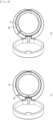
- FIG. 1 is a perspective view showing a container according to an embodiment of the present invention
- FIG. 2 is an exploded perspective view showing the container according to the embodiment of the present invention
- FIG. 3 is an exploded perspective view showing a second container part and a cover part of the container according to the embodiment of the present invention.
- FIG. 1a shows a state where a container is closed
- FIG. 1b shows a state where the container is open.
- a container 1000 includes a first container part 100, a second container part 200, a locking part 300, and/or a covering part 400.
- the first container part 100 stores a given content therein.
- the given content is a solid, semi-solid, powder, liquid or gel cosmetic content.
- the content may be a base, blusher, shade, eyeshadow, eyebrow, lotion, milk lotion, moisture lotion, nutrition lotion, skin lotion, skin softer, skin toner, astringent, massage cream, nutrition cream, whitening essence, tone-up cream, sunblock, sun cream, sun milk, BB cream, foundation, CC cream, concealer, eye cream, primer, and the like.
- the content may not be limited thereto, and therefore, the content may include different formulations or types of cosmetics or medicines.
- the first container part 100 has a circular, oval, or polygonal base surface and a peripheral surface extending upward from the base surface and is open on top thereof to form a storage space portion in which the content is stored.
- the first container part 100 has various shapes, such as a cylinder, a cone, a truncated cone, a semi-sphere, a polygonal column, a polygonal cone, and a polygonal truncated cone whose tops are open.
- the polygonal column, the polygonal cone, and the polygonal truncated cone have flat surfaces or curved surfaces with given curvatures.
- the first container part 100 has at least a portion made of a metal material such as aluminum, copper, titanium, magnesium, iron, and the like.
- the first container part 100 may be made of a synthetic resin such as polypropylene (PP), polyethylene terephthalate (PET), polyethylene terephthalate glycol-modified (PETG), and the like or a natural material such as a fabric, paper, fibers, Tencel, silk, and the like.
- the second container part 200 has a coupler 210 located on a top thereof to fix the first container part 100 thereto.
- the coupler 210 serves to surround the outer periphery of the first container part 100 and thus fix the first container part 100 thereto.
- the coupler 210 includes a pressurizer 211, vertical grooves 212, a guide groove 213, a first locking projection 214 and/or a locking groove 215.
- the pressurizer 211 serves to fix the first container part 100 to the second container part 200 or separate the first container part 100 from the second container part 200 according to rotations of the locking part 300.
- the pressurizer 211 is bent inward from the coupler 210 and pressurizes the outer peripheral surface of the first container part 100, so that the first container part 100 is fixed to the second container part 200.
- the first direction represents the clockwise direction, but without being limited thereto, the first direction may represent a counterclockwise direction.
- the locking part 300 rotates in a second direction (e.g., in the counterclockwise direction) opposite to the first direction with respect to the coupler 210 in the state where the pressurizer 211 pressurizes the first container part 100
- the pressurizer 211 which has been bent inward from the coupler 210, returns to its original position. Accordingly, the pressurization of the pressurizer 211 against the first container part 100 is released, so that the first container part 100 is separated from the coupler 210. If the content stored in the first container part 100 is all consumed, the first container part 100 is easily separated from the coupler 210 by means of the rotation of the locking part 300, so that the first container part 100 is replaced with a new first container part 100.
- first container part 100 and the second container part 200 have different materials (for example, if the first container part 100 is made of an aluminum material and the second container part 200 is made of a plastic material), the first container part 100 is easily separated and discharged from the second container part 200.
- the pressurizer 211 has at least a portion made of an elastic material so that it is bent inward from the coupler 210 or returns to its original position according to the rotational directions of the locking part 300.
- the pressurizer 121 may not be limited thereto.
- the pressurizer 211 extends by a given length in the second direction on top of the coupler 210 (in detail, on top of one side surface of the coupler 210).
- the pressurizer 211 extending by the given length allows a relatively large area thereof to come into contact with the locking part 300 (especially, a slant surface 311), receives a pressurizing force from the contact, and is thus easily bent inward from the coupler 210.
- the plurality of vertical grooves 212 are formed so that when the locking part 300 rotates, they serve to facilitate elastic deformation of the pressurizer 211.
- the vertical grooves 212 are spaced apart from one another along the inner surface of the pressurizer 211.
- the elastic deformation of the pressurizer 211 is more easily made by means of the vertical grooves 212, so that the pressurizer 211 comes into contact with the outer peripheral surface of the first container part 100 more tightly to pressurizingly fix the first container part 100 thereto.
- the pressurizer 211 is elastically deformed correspondingly to the size of the first container part 100 by means of the vertical grooves 212. Irrespective of the size of the first container part 100, that is, the pressurizer 211 can come into close contact with the outer peripheral surface of the first container part 100 to pressurizingly fix the first container part 100 thereto.
- the guide groove 213 is concavely formed along the outer peripheral surface of the coupler 210.
- the guide groove 213 serves to insert a guide protrusion 320 of the locking part 300 so that when the locking part 300 rotates with respect to the second container part 200, the guide protrusion 320 moves along the guide groove 213. That is, when the locking part 300 rotates, the rotational height of the locking part 300 is constantly kept by means of the guide groove 213 and the guide protrusion 320.
- the guide groove 213 extends from one point of the outer peripheral surface of the coupler 210 to one point of the pressurizer 211 in a circumferential direction.
- the locking part 300 rotates in the first or second direction more stably by means of the user, thereby allowing the first container part 100 to be coupled to or separated from the second container part 200.
- the first locking projection 214 is formed on the bottom of the coupler 210 and comes into contact with a second locking projection 312 of the locking part 300 rotating in the first direction to prevent the locking part 300 from additionally rotating in the first direction.
- the pressurizer 211 extends in the second direction from top of one side surface of the coupler 210, and the first locking projection 214 protrudes by a given length from the bottom (that is, under the pressurizer 211) of one side surface of the coupler 210 where the pressurizer 211 is formed in the second direction.
- the locking groove 215 is formed on the outer peripheral surface of the coupler 210, and as a locking protrusion 330 of the locking part 300 is inserted into the locking groove 215, the locking part 300 is prevented from arbitrarily rotating.
- the locking groove 215 is formed on the outer peripheral surface of the first locking projection 214, thereby preventing the locking part 300 from additionally rotating in the first direction by means of the first locking projection 214, while preventing the locking part 300 from rotating in the first direction and arbitrarily rotating in the second direction by means of the locking groove 215.
- a plurality of couplers 210 are provided to surround different regions of the outer peripheral surface of the first container part 100.
- a first coupler 210-1 and a second coupler 210-2 are provided as the couplers 210.
- the first coupler 210-1 and the second coupler 210-2 are spaced apart from each other to surround different regions of the first container part 100.
- the pressurizers 211 extend in the second direction from top of one side of the first coupler 210-1 and from top of one side of the second coupler 210-2, and they pressurize the different regions of the outer peripheral surface of the first container part 100, thereby fixing the first container part 100 thereto.
- the first container part 100 is fixed to the couplers 210 more tightly.
- two couplers 210 are provided, but without being limited thereto, three or more couplers 210 may be provided.
- the second container part 200 has a first hinge 220 recessed on one side thereof.
- the first hinge 220 serves to insert the covering part 400 (especially a second hinge 410), thereby allowing the second container part 200 to be detachably coupled to the covering part 400.
- the first hinge 220 includes an incised portion 221 and at least one or more hinge protrusions 222.
- the incised portion 221 is recessed inward from the second container part 200 and inserts a protruding portion 411 of the covering part 400 thereinto.
- the hinge protrusions 222 protrude inward from the incised portion 221 and are inserted into hinge grooves 412 of the covering part 400.
- the hinge protrusions 222 protrude inward from the facing inner surfaces of the incised portion 221.
- the second container part 200 is made of a recyclable material.
- the second container part 200 is made of a reusable material having no post processing, and therefore, the second container part 200 is eco-friendly.
- the second container part 200 is made of polypropylene (PP), polyethylene terephthalate (PET), or polyethylene terephthalate glycol-modified (PETG).
- PP polypropylene
- PET polyethylene terephthalate
- PETG polyethylene terephthalate glycol-modified
- the second container part 200 may be made of other materials, without being limited thereto.
- the locking part 300 rotates with respect to the couplers 210 to allow the first container part 100 to be fixed to or separated from the couplers 210. To do this, the locking part 300 is rotatably coupled to the couplers 210 in such a way as to surround the outer peripheral surfaces of the couplers 210.
- the locking part 300 includes guide portions 310, the guide protrusions 320, and the locking protrusions 330.
- the guide portions 310 protrude from the inner peripheral surface of the locking part 300 and allow the pressurizers 211 to be bent inward from the couplers 210 according to the rotation of the locking part 300.
- each guide portion 310 has the slant surface 311 formed in a horizontal direction on a given region thereof.
- the slant surface 311 increases in a protruding height from the guide portion 310 in the second direction. If the locking part 300 rotates in the first direction, accordingly, the pressurizers 211 come into close contact with the slant surfaces 311 and move relative to the locking part 300, so that they are bent inward from the couplers 210.
- the guide portions 310 of the locking part 300 are alignedly inserted into spaces between the first coupler 210-1 and the second coupler 210-2.
- the guide portions 310 of the locking part 300 are first aligned to be located above the spaces between the first coupler 210-1 and the second coupler 210-2, and next, the locking part 300 moves down to allow the guide portions 310 to be inserted into the corresponding spaces.
- the slant surfaces 311 are aligned with positions and heights corresponding to the pressurizers 211, and the guide protrusions 320 are aligned with positions corresponding to the guide grooves 213, so that if the locking part 300 rotates, the second container part 200 and the locking part 300 are coupled to each other.
- each guide portion 310 has the second locking projection 312 protruding from the underside of the slant surface 311.
- the second locking projection 312 comes into contact with the end portion of the first locking projection 214 of each coupler 210, thereby limiting the movement of the locking part 300 rotating in the first direction.
- the second locking projection 312 moves under the corresponding pressurizer 211 and comes into contact with the end portion of the first locking projection 214, thereby preventing the locking part 300 from additionally rotating in the first direction.
- the pressurizer 211 extends in the second direction from top of one side surface of the coupler 210, the first locking projection 214 protrudes from the bottom of the coupler 210, and the second locking projection 312 extends in the first direction.
- the guide protrusion 320 protrudes from the inner peripheral surface of the locking part 300 so that it is inserted into the guide groove 213 of the coupler 210, if the locking part 300 rotates, and moves along the guide groove 213.
- the guide protrusion 320 extends by a given length in a horizontal direction (or in the rotating direction of the locking part 300). While the locking part 300 is rotating in the first direction, the pressurizer 211 is bent inward from the coupler 210 and thus generates an external force (that is, an elastic restoring force of the pressurizer 211), and even under such an external force, the locking part 300 rotates to a given height, without escaping from the coupler 210.
- the locking protrusion 330 is inserted into the locking groove 215 of the coupler 210, thereby preventing the locking part 300 from arbitrarily rotating. If an external force greater than a given size in the second direction is applied to the locking part 300 in the state where the locking protrusion 330 is inserted into the locking groove 215, the locking protrusion 330 escapes from the locking groove 215, thereby allowing the locking part 300 to rotate in the second direction.
- the locking protrusion 330 is formed on the inner peripheral surface of the locking part 300 in such a way as to be spaced apart from the guide portion 310 by a given distance
- the locking groove 215 is formed on the outer peripheral surface of the first locking projection 214 in such a way as to correspond to the locking protrusion 330. In this case, if the locking part 300 rotates in the first direction to allow the second locking projection 312 to come into contact with the end portion of the first locking projection 214, the locking protrusion 330 can be inserted into the locking groove 215.
- the covering part 400 is detachably coupled to one side of the second container part 200 in such a way as to rotate with respect to the second container part 200 to open and close the second container part 200.
- the covering part 400 has the second hinge 410 protruding therefrom in such a way as to correspond to the first hinge 220 of the second container part 200. That is, as the second hinge 410 is inserted into the first hinge 220, the covering part 400 is detachably coupled to the second container part 200. Accordingly, the covering part 400 is simply fitted to the second container part 200, without having any existing hinge pin used to rotatably couple the container and the cover to each other.
- the second hinge 410 includes the protruding portion 411 protruding downward therefrom and at least one or more hinge grooves 412 recessed inward from the protruding portion 411.
- the plurality of hinge protrusions 222 protrude inward from the facing inner surfaces of the incised portion 221
- the plurality of hinge grooves 412 are recessed inward from both sides of the protruding portion 411 in such a way as to correspond to the hinge protrusions 211.
- the hinge protrusions 222 are fittedly coupled to the hinge grooves 412, so that the covering part 400 is rotatable with respect to the second container part 200 around the hinge protrusions 222.
- an open portion 413 is formed on an open region of the hinge groove 412.
- the open portion 413 extends downward from at least a portion of the open region of the hinge groove 412 and thus forms a path for inserting the hinge protrusion 222 when the second hinge 410 is coupled to the first hinge 220. That is, if the second container part 200 and the covering part 400 are coupled to each other to allow the second hinge 410 to be inserted into the first hinge 220, the hinge protrusions 222 are easily inserted into the hinge grooves 412 by means of the open portions 413. Further, for example, the open portions 413 increase in width toward the lower sides thereof. As a result, the hinge protrusions 222 are more easily inserted into the hinge grooves 412, and after the insertion, they are prevented from escaping from the hinge grooves 412.
- the covering part 400 has at least a portion made of a transparent or semi-transparent material.
- the content stored in the first container part 100 is seen outside of the container 1000, thereby allowing the type, color, and remaining amount of the content to be checked by the user.
- the covering part 400 is made of polypropylene (PP), polyethylene terephthalate (PET), or polyethylene terephthalate glycol-modified (PETG), which is the same material as the second container part 200.
- the covering part 400 may be made of a different material from the second container part 200, without being limited thereto.
- the container 1000 as shown in FIGs. 1 to 3 is just exemplary, and therefore, the container 1000 may have various configurations according to embodiments of the present invention.
- FIGs. 4 to 6 show operations of the container according to the embodiment of the present invention.
- FIGs. 4 and 5 are perspective and plan views showing the container 1000 where the first container part 100 is removed.
- FIGs. 4a and 5a show states where the pressurization of the pressurizers 211 against the first container part 100 is released
- FIGs. 4b and 5b show states where the first container part 100 is pressurizedly fixed to the pressurizers 211.
- FIG. 6a shows a state where the first container part 100 is pressurized against the pressurizers 211
- FIG. 6b shows a state where the first container part 100 is separated from the second container part 200.
- the pressurizers 211 move relative to the locking part 300 and thus come into contact with the slant surfaces 311 of the guide portions 310, so that they are bent inward from the couplers 210. As a result, the pressurizers 211 pressurize the outer peripheral surface of the first container part 100 to allow the first container part 100 to be fixed to the second container part 200.
- the second locking projections 312 of the locking part 300 move in the first direction under the pressurizers 211 and come into contact with the end portions of the first locking projections 214, so that the locking part 300 is prevented from additionally rotating in the first direction.
- the locking protrusions 330 of the locking part 300 are inserted into the locking grooves 215 of the couplers 210, so that the locking part 300 is prevented from arbitrarily rotating in the first and second directions.
- the pressurizers 211 which have been bent inward from the couplers 210, return to their original position. As a result, the pressurization of the pressurizers 211 against the first container part 100 is released to allow the first container part 100 to be separated from the couplers 210.
- the operations of the container 1000 as shown in FIGs. 4 to 6 are just exemplary, and therefore, the operations of the container 1000 may be freely performed according to embodiments of the present invention.
Landscapes
- Engineering & Computer Science (AREA)
- Mechanical Engineering (AREA)
- Packages (AREA)
- Closures For Containers (AREA)
- Containers And Packaging Bodies Having A Special Means To Remove Contents (AREA)
- Rigid Containers With Two Or More Constituent Elements (AREA)
- Table Devices Or Equipment (AREA)
- Details Of Rigid Or Semi-Rigid Containers (AREA)
Abstract
Description
- The present invention relates to a container.
- Among cosmetics, color cosmetics such as eyeshadows, shades, blushers, foundations, and the like are provided in the form of a compact container having an inner container for storing a cosmetic content and an outer container for fixing the inner container thereto. As the inner container and the outer container of the compact container are formed integrally with each other, it is impossible to separate them from each other, and otherwise, they are tightly coupled to each other by means of an adhesive or the like, it is hard to separate the inner container from the outer container. As a result, after the cosmetic content is used up, it is difficult that only the inner container is replaced with new one to allow the outer container to be reusable.
- In the case where the inner container and the outer container of the compact container are made of different materials from each other, further, they are necessary to be separated from each other in a process where the compact container is thrown away. In the case of the conventional compact container, however, it is impossible to separate the inner container from the outer container, or even if possible, the remaining cosmetic material in the separation process may be applied dirtily to a hand. Further, nails may be damaged due to the separation process. As a result, such a separation process may cause many inconveniences.
- Generally, the compact container is configured to have a container part in which a given content is stored and a covering part for opening and closing the container part. The covering part is rotatably coupled to one side of the container part, and a hinge pin made of a metal material is used to rotate the covering part. In this case, it is hard to separate only the hinge pin from the compact container made of a synthetic resin, thereby making it difficult to recycle the compact container.
- Accordingly, to solve the above-mentioned problems occurring in the related art, it is an object of the present invention to provide a container that is capable of allowing a first container part in which a given content is stored to be fixed or easily separated from a second container part by means of simple rotations of a locking part.
- The technical problems to be achieved through the present invention are not limited as mentioned above, and other technical problems not mentioned herein will be obviously understood by one of ordinary skill in the art through the following description.
- To accomplish the above-mentioned objects, according to the present invention, there is provided a container. The container may include: a first container part for storing a given content therein; a second container part having couplers disposed on a top thereof in such a way as to surroundingly fix the outer peripheral surface of the first container part thereto; and a locking part rotatably coupled to the couplers in such a way as to surround the outer peripheral surfaces of the couplers, wherein each coupler has a pressurizer bent inward therefrom, if the locking part rotates in a first direction with respect to the couplers, to allow the outer peripheral surface of the first container part to be pressurizedly fixed thereto.
- According to the present invention, the container is configured to allow the first container part in which the given content is stored to be fixed or easily separated from the second container part by means of the simple rotations of the locking part, so that only the first container part is replaced with new one, thereby allowing the container to be recyclable.
- According to the present invention, further, the container is configured to allow the first container part to be easily separated and discharged from the second container part if the first container part and the second container part are made of different materials, thereby improving the conveniences of use.
- According to the present invention, furthermore, the container is configured to allow the second container part and the covering part to be detachably fitted to each other, so that they are easily coupled to each other, without any hinge pin, thereby allowing the container to be recyclable.
- According to the present invention, additionally, the container is configured to have at least a portion made of a transparent or semi-transparent material, so that the type, color, and remaining amount of the content stored therein to be easily checked by the user.
- To allow the drawings as will be mentioned in the description of the present invention to be more sufficiently understood, the brief description of the drawings may be provided.
-
FIG. 1 is a perspective view showing a container according to an embodiment of the present invention. -
FIG. 2 is an exploded perspective view showing the container according to the embodiment of the present invention. -
FIG. 3 is an exploded perspective view showing a second container part and a covering part of the container according to the embodiment of the present invention. -
FIGs. 4 to 6 show operations of the container according to the embodiment of the present invention. - According to an embodiment of the present invention is provided a container. The container includes: a first container part for storing a given content therein; a second container part having couplers disposed on a top thereof in such a way as to surroundingly fix the outer peripheral surface of the first container part thereto; and a locking part rotatably coupled to the couplers in such a way as to surround the outer peripheral surfaces of the couplers, wherein each coupler has a pressurizer bent inward therefrom, if the locking part rotates in a first direction with respect to the couplers, to allow the outer peripheral surface of the first container part to be pressurizedly fixed thereto.
- Further, if the locking part rotates in a second direction opposite to the first direction with respect to the couplers, the pressurizers return to original positions thereof to allow the pressurization against the first container part to be released, so that the first container part is separated from the couplers.
- Furthermore, the locking part has guide portions protruding from the inner peripheral surface thereof and having slant surfaces formed in a horizontal direction on given regions thereof, and if the locking part rotates in the first direction, the pressurizers come into close contact with the slant surfaces and move relative to the locking part, so that the pressurizers are bent inward from the couplers.
- Besides, the pressurizers extend by a given length in the second direction from tops of the couplers.
- Moreover, the couplers include a first coupler and a second coupler spaced apart from each other to surround different regions of the outer peripheral surface of the first container part, and the pressurizers extend in the second direction from top of one side of the first coupler and from top of one side of the second coupler.
- Further, if the guide portions of the locking part are inserted into spaces between the first coupler and the second coupler, the slant surfaces are aligned with positions corresponding to the pressurizers.
- Furthermore, the locking part has at least one or more guide protrusions protruding from the inner peripheral surface thereof, and the couplers have at least one or more guide grooves concavely formed on the outer peripheral surfaces thereof in such a way as to correspond to the guide protrusions, so that if the locking part rotates, the guide protrusions move along the guide grooves to allow the locking part to rotate at a constant height.
- Additionally, each guide groove extends from one point of the outer peripheral surface of the corresponding coupler to one point of the corresponding pressurizer in a circumferential direction.
- Further, each coupler has a first locking projection formed on the bottom thereof, and each guide portion has a second locking projection protruding from the bottom of the slant surface thereof, so that if the locking part rotates in the first direction, the second locking projections of the locking part move under the pressurizers and come into contact with the end portions of the first locking projections to allow the locking part to be prevented from additionally rotating in the first direction.
- Moreover, the locking part has locking protrusions formed on the inner peripheral surface of in such a way as to be spaced apart from the guide portions by a given distance, and the couplers have locking grooves formed on the outer peripheral surfaces of the first locking projections in such a way as to correspond to the locking protrusions, so that the locking protrusions are inserted into the locking grooves to allow the locking part to be prevented from arbitrarily rotating.
- The container according to the present invention further includes a covering part detachably coupled to one side of the second container part in such a way as to rotate with respect to the second container part to open and close the second container part.
- Further, the second container part has a first hinge recessed inward from one side thereof, and the covering part has a second hinge protruding from one side thereof in such a way as to be inserted into the first hinge, so that if the second hinge is inserted into the first hinge, the covering part is detachably coupled to the second container part.
- Furthermore, the first hinge includes: an incised portion recessed inward from the second container part; and at least one or more hinge protrusions protruding inward from the incised portion, and the second hinge includes: a protruding portion protruding downward from the covering part; and at least one or more hinge grooves recessed inward from the protruding portion in such a way as to correspond to the hinge protrusions, whereby if the second hinge is inserted into the first hinge, the hinge protrusions are fittedly coupled to the hinge grooves to allow the covering part to be rotatable with respect to the second container part around the hinge protrusions.
- Besides, the covering part has at least a portion made of a transparent or semi-transparent material so that the given content stored in the first container part is seen outside the container.
- Hereinafter, exemplary embodiments of the present invention will be described in detail with reference to the accompanying drawings. Further, a method for configuring and using a device according to the embodiment of the present invention will be explained in detail with reference to the attached drawings and specification. In the drawings, reference numerals or symbols, with respect to the same elements, even though they may be displayed in different drawings, such elements use same reference numerals as much as possible. Further, top, bottom, left and right directions as will be described below are determined with reference to the drawings, and accordingly, the scope of the present invention is not necessarily restricted to the corresponding directions.
- It shall be understood that, although the terms "first," "second," etc. may be used herein to describe various information, the information should not be limited by these terms. These terms are only used to distinguish one category of information from another. For example, a first element may be named a second element without departing from the scope of the present invention. Likewise, a second element may be named a first element.
- Terms used in this application are used to only describe specific exemplary embodiments and are not intended to restrict the present invention. An expression referencing a singular value additionally refers to a corresponding expression of the plural number, unless explicitly limited otherwise by the context. In this application, terms, such as "comprise", "include", or "have", are intended to designate those characteristics, numbers, steps, operations, elements, or parts which are described in the specification, or any combination of them that exist, and it should be understood that they do not preclude the possibility of the existence or possible addition of one or more additional characteristics, numbers, steps, operations, elements, or parts, or combinations thereof.
- In the entire specification, when it is said that one element is described as being "connected" or "coupled" to the other element, one element may be directly connected or coupled to the other element, but it should be understood that another element may be present between the two elements. Further, when it is said that one portion is described as "includes" any component, one element further may include other components unless no specific description is suggested.
-
FIG. 1 is a perspective view showing a container according to an embodiment of the present invention,FIG. 2 is an exploded perspective view showing the container according to the embodiment of the present invention, andFIG. 3 is an exploded perspective view showing a second container part and a cover part of the container according to the embodiment of the present invention. In detail,FIG. 1a shows a state where a container is closed, andFIG. 1b shows a state where the container is open. - Referring to
FIGs. 1 to 3 , acontainer 1000 according to an embodiment of the present invention includes afirst container part 100, asecond container part 200, alocking part 300, and/or a coveringpart 400. - The
first container part 100 stores a given content therein. In this case, the given content is a solid, semi-solid, powder, liquid or gel cosmetic content. For example, the content may be a base, blusher, shade, eyeshadow, eyebrow, lotion, milk lotion, moisture lotion, nutrition lotion, skin lotion, skin softer, skin toner, astringent, massage cream, nutrition cream, whitening essence, tone-up cream, sunblock, sun cream, sun milk, BB cream, foundation, CC cream, concealer, eye cream, primer, and the like. However, the content may not be limited thereto, and therefore, the content may include different formulations or types of cosmetics or medicines. - For example, the
first container part 100 has a circular, oval, or polygonal base surface and a peripheral surface extending upward from the base surface and is open on top thereof to form a storage space portion in which the content is stored. In detail, thefirst container part 100 has various shapes, such as a cylinder, a cone, a truncated cone, a semi-sphere, a polygonal column, a polygonal cone, and a polygonal truncated cone whose tops are open. In this case, the polygonal column, the polygonal cone, and the polygonal truncated cone have flat surfaces or curved surfaces with given curvatures. - Further, the
first container part 100 has at least a portion made of a metal material such as aluminum, copper, titanium, magnesium, iron, and the like. However, of course, thefirst container part 100 may be made of a synthetic resin such as polypropylene (PP), polyethylene terephthalate (PET), polyethylene terephthalate glycol-modified (PETG), and the like or a natural material such as a fabric, paper, fibers, Tencel, silk, and the like. - The
second container part 200 has acoupler 210 located on a top thereof to fix thefirst container part 100 thereto. Thecoupler 210 serves to surround the outer periphery of thefirst container part 100 and thus fix thefirst container part 100 thereto. - According to the embodiment of the present invention, the
coupler 210 includes apressurizer 211,vertical grooves 212, aguide groove 213, afirst locking projection 214 and/or a lockinggroove 215. - The
pressurizer 211 serves to fix thefirst container part 100 to thesecond container part 200 or separate thefirst container part 100 from thesecond container part 200 according to rotations of the lockingpart 300. - For example, if the locking
part 300 rotates in a first direction (e.g., in a clockwise direction) with respect to thecoupler 210, thepressurizer 211 is bent inward from thecoupler 210 and pressurizes the outer peripheral surface of thefirst container part 100, so that thefirst container part 100 is fixed to thesecond container part 200. InFIG. 2 , the first direction represents the clockwise direction, but without being limited thereto, the first direction may represent a counterclockwise direction. - Further, for example, if the locking
part 300 rotates in a second direction (e.g., in the counterclockwise direction) opposite to the first direction with respect to thecoupler 210 in the state where thepressurizer 211 pressurizes thefirst container part 100, thepressurizer 211, which has been bent inward from thecoupler 210, returns to its original position. Accordingly, the pressurization of thepressurizer 211 against thefirst container part 100 is released, so that thefirst container part 100 is separated from thecoupler 210. If the content stored in thefirst container part 100 is all consumed, thefirst container part 100 is easily separated from thecoupler 210 by means of the rotation of the lockingpart 300, so that thefirst container part 100 is replaced with a newfirst container part 100. Further, if thefirst container part 100 and thesecond container part 200 have different materials (for example, if thefirst container part 100 is made of an aluminum material and thesecond container part 200 is made of a plastic material), thefirst container part 100 is easily separated and discharged from thesecond container part 200. - According to the embodiment of the present invention, the
pressurizer 211 has at least a portion made of an elastic material so that it is bent inward from thecoupler 210 or returns to its original position according to the rotational directions of the lockingpart 300. However, the pressurizer 121 may not be limited thereto. - According to the embodiment of the present invention, the
pressurizer 211 extends by a given length in the second direction on top of the coupler 210 (in detail, on top of one side surface of the coupler 210). When the lockingpart 300 rotates in the first direction, thepressurizer 211 extending by the given length allows a relatively large area thereof to come into contact with the locking part 300 (especially, a slant surface 311), receives a pressurizing force from the contact, and is thus easily bent inward from thecoupler 210. - The plurality of
vertical grooves 212 are formed so that when the lockingpart 300 rotates, they serve to facilitate elastic deformation of thepressurizer 211. For example, thevertical grooves 212 are spaced apart from one another along the inner surface of thepressurizer 211. The elastic deformation of thepressurizer 211 is more easily made by means of thevertical grooves 212, so that thepressurizer 211 comes into contact with the outer peripheral surface of thefirst container part 100 more tightly to pressurizingly fix thefirst container part 100 thereto. - Even if the size of the
first container part 100 is changed within a given range, further, thepressurizer 211 is elastically deformed correspondingly to the size of thefirst container part 100 by means of thevertical grooves 212. Irrespective of the size of thefirst container part 100, that is, thepressurizer 211 can come into close contact with the outer peripheral surface of thefirst container part 100 to pressurizingly fix thefirst container part 100 thereto. - The
guide groove 213 is concavely formed along the outer peripheral surface of thecoupler 210. Theguide groove 213 serves to insert aguide protrusion 320 of the lockingpart 300 so that when the lockingpart 300 rotates with respect to thesecond container part 200, theguide protrusion 320 moves along theguide groove 213. That is, when the lockingpart 300 rotates, the rotational height of the lockingpart 300 is constantly kept by means of theguide groove 213 and theguide protrusion 320. - According to the embodiment of the present invention, the
guide groove 213 extends from one point of the outer peripheral surface of thecoupler 210 to one point of thepressurizer 211 in a circumferential direction. As theguide groove 213 extends up to the outer peripheral surface of thepressurizer 211, the lockingpart 300 rotates in the first or second direction more stably by means of the user, thereby allowing thefirst container part 100 to be coupled to or separated from thesecond container part 200. - The
first locking projection 214 is formed on the bottom of thecoupler 210 and comes into contact with asecond locking projection 312 of the lockingpart 300 rotating in the first direction to prevent thelocking part 300 from additionally rotating in the first direction. For example, thepressurizer 211 extends in the second direction from top of one side surface of thecoupler 210, and thefirst locking projection 214 protrudes by a given length from the bottom (that is, under the pressurizer 211) of one side surface of thecoupler 210 where thepressurizer 211 is formed in the second direction. - The locking
groove 215 is formed on the outer peripheral surface of thecoupler 210, and as a lockingprotrusion 330 of the lockingpart 300 is inserted into the lockinggroove 215, the lockingpart 300 is prevented from arbitrarily rotating. For example, the lockinggroove 215 is formed on the outer peripheral surface of thefirst locking projection 214, thereby preventing the lockingpart 300 from additionally rotating in the first direction by means of thefirst locking projection 214, while preventing the lockingpart 300 from rotating in the first direction and arbitrarily rotating in the second direction by means of the lockinggroove 215. - According to the embodiment of the present invention, a plurality of
couplers 210 are provided to surround different regions of the outer peripheral surface of thefirst container part 100. For example, a first coupler 210-1 and a second coupler 210-2 are provided as thecouplers 210. The first coupler 210-1 and the second coupler 210-2 are spaced apart from each other to surround different regions of thefirst container part 100. In this case, thepressurizers 211 extend in the second direction from top of one side of the first coupler 210-1 and from top of one side of the second coupler 210-2, and they pressurize the different regions of the outer peripheral surface of thefirst container part 100, thereby fixing thefirst container part 100 thereto. Like this, as the plurality of regions (especially, the outer peripheral surfaces in opposite directions to each other) of thefirst container part 100 are pressurized and fixed, thefirst container part 100 is fixed to thecouplers 210 more tightly. InFIGs. 2 and3 , twocouplers 210 are provided, but without being limited thereto, three ormore couplers 210 may be provided. - The
second container part 200 has afirst hinge 220 recessed on one side thereof. Thefirst hinge 220 serves to insert the covering part 400 (especially a second hinge 410), thereby allowing thesecond container part 200 to be detachably coupled to the coveringpart 400. - According to the embodiment of the present invention, the
first hinge 220 includes an incisedportion 221 and at least one ormore hinge protrusions 222. The incisedportion 221 is recessed inward from thesecond container part 200 and inserts a protrudingportion 411 of the coveringpart 400 thereinto. Further, thehinge protrusions 222 protrude inward from the incisedportion 221 and are inserted intohinge grooves 412 of the coveringpart 400. For example, thehinge protrusions 222 protrude inward from the facing inner surfaces of the incisedportion 221. - According to the embodiment of the present invention, the
second container part 200 is made of a recyclable material. Thesecond container part 200 is made of a reusable material having no post processing, and therefore, thesecond container part 200 is eco-friendly. For example, thesecond container part 200 is made of polypropylene (PP), polyethylene terephthalate (PET), or polyethylene terephthalate glycol-modified (PETG). However, thesecond container part 200 may be made of other materials, without being limited thereto. - The locking
part 300 rotates with respect to thecouplers 210 to allow thefirst container part 100 to be fixed to or separated from thecouplers 210. To do this, the lockingpart 300 is rotatably coupled to thecouplers 210 in such a way as to surround the outer peripheral surfaces of thecouplers 210. - According to the embodiment of the present invention, the locking
part 300 includesguide portions 310, theguide protrusions 320, and the lockingprotrusions 330. - The
guide portions 310 protrude from the inner peripheral surface of the lockingpart 300 and allow thepressurizers 211 to be bent inward from thecouplers 210 according to the rotation of the lockingpart 300. - To do this, each
guide portion 310 has theslant surface 311 formed in a horizontal direction on a given region thereof. For example, theslant surface 311 increases in a protruding height from theguide portion 310 in the second direction. If the lockingpart 300 rotates in the first direction, accordingly, thepressurizers 211 come into close contact with the slant surfaces 311 and move relative to the lockingpart 300, so that they are bent inward from thecouplers 210. - According to the embodiment of the present invention, if the first coupler 210-1 and the second coupler 210-2 are provided as the
couplers 210, theguide portions 310 of the lockingpart 300 are alignedly inserted into spaces between the first coupler 210-1 and the second coupler 210-2. To couple the lockingpart 300 to thecouplers 210, that is, theguide portions 310 of the lockingpart 300 are first aligned to be located above the spaces between the first coupler 210-1 and the second coupler 210-2, and next, the lockingpart 300 moves down to allow theguide portions 310 to be inserted into the corresponding spaces. Accordingly, the slant surfaces 311 are aligned with positions and heights corresponding to thepressurizers 211, and theguide protrusions 320 are aligned with positions corresponding to theguide grooves 213, so that if the lockingpart 300 rotates, thesecond container part 200 and the lockingpart 300 are coupled to each other. - According to the embodiment of the present invention, each
guide portion 310 has thesecond locking projection 312 protruding from the underside of theslant surface 311. Thesecond locking projection 312 comes into contact with the end portion of thefirst locking projection 214 of eachcoupler 210, thereby limiting the movement of the lockingpart 300 rotating in the first direction. In detail, if the lockingpart 300 rotates in the first direction, thesecond locking projection 312 moves under thecorresponding pressurizer 211 and comes into contact with the end portion of thefirst locking projection 214, thereby preventing the lockingpart 300 from additionally rotating in the first direction. To do this, for example, thepressurizer 211 extends in the second direction from top of one side surface of thecoupler 210, thefirst locking projection 214 protrudes from the bottom of thecoupler 210, and thesecond locking projection 312 extends in the first direction. - The
guide protrusion 320 protrudes from the inner peripheral surface of the lockingpart 300 so that it is inserted into theguide groove 213 of thecoupler 210, if the lockingpart 300 rotates, and moves along theguide groove 213. For example, theguide protrusion 320 extends by a given length in a horizontal direction (or in the rotating direction of the locking part 300). While the lockingpart 300 is rotating in the first direction, thepressurizer 211 is bent inward from thecoupler 210 and thus generates an external force (that is, an elastic restoring force of the pressurizer 211), and even under such an external force, the lockingpart 300 rotates to a given height, without escaping from thecoupler 210. - The locking
protrusion 330 is inserted into the lockinggroove 215 of thecoupler 210, thereby preventing the lockingpart 300 from arbitrarily rotating. If an external force greater than a given size in the second direction is applied to the lockingpart 300 in the state where the lockingprotrusion 330 is inserted into the lockinggroove 215, the lockingprotrusion 330 escapes from the lockinggroove 215, thereby allowing the lockingpart 300 to rotate in the second direction. For example, the lockingprotrusion 330 is formed on the inner peripheral surface of the lockingpart 300 in such a way as to be spaced apart from theguide portion 310 by a given distance, and the lockinggroove 215 is formed on the outer peripheral surface of thefirst locking projection 214 in such a way as to correspond to the lockingprotrusion 330. In this case, if the lockingpart 300 rotates in the first direction to allow thesecond locking projection 312 to come into contact with the end portion of thefirst locking projection 214, the lockingprotrusion 330 can be inserted into the lockinggroove 215. - The covering
part 400 is detachably coupled to one side of thesecond container part 200 in such a way as to rotate with respect to thesecond container part 200 to open and close thesecond container part 200. To do this, the coveringpart 400 has thesecond hinge 410 protruding therefrom in such a way as to correspond to thefirst hinge 220 of thesecond container part 200. That is, as thesecond hinge 410 is inserted into thefirst hinge 220, the coveringpart 400 is detachably coupled to thesecond container part 200. Accordingly, the coveringpart 400 is simply fitted to thesecond container part 200, without having any existing hinge pin used to rotatably couple the container and the cover to each other. - According to the embodiment of the present invention, the
second hinge 410 includes the protrudingportion 411 protruding downward therefrom and at least one ormore hinge grooves 412 recessed inward from the protrudingportion 411. For example, if the plurality ofhinge protrusions 222 protrude inward from the facing inner surfaces of the incisedportion 221, the plurality ofhinge grooves 412 are recessed inward from both sides of the protrudingportion 411 in such a way as to correspond to thehinge protrusions 211. As thesecond hinge 410 is inserted into thefirst hinge 220, thehinge protrusions 222 are fittedly coupled to thehinge grooves 412, so that the coveringpart 400 is rotatable with respect to thesecond container part 200 around thehinge protrusions 222. - According to the embodiment of the present invention, an
open portion 413 is formed on an open region of thehinge groove 412. Theopen portion 413 extends downward from at least a portion of the open region of thehinge groove 412 and thus forms a path for inserting thehinge protrusion 222 when thesecond hinge 410 is coupled to thefirst hinge 220. That is, if thesecond container part 200 and the coveringpart 400 are coupled to each other to allow thesecond hinge 410 to be inserted into thefirst hinge 220, thehinge protrusions 222 are easily inserted into thehinge grooves 412 by means of theopen portions 413. Further, for example, theopen portions 413 increase in width toward the lower sides thereof. As a result, thehinge protrusions 222 are more easily inserted into thehinge grooves 412, and after the insertion, they are prevented from escaping from thehinge grooves 412. - According to the embodiment of the present invention, the covering
part 400 has at least a portion made of a transparent or semi-transparent material. As a result, the content stored in thefirst container part 100 is seen outside of thecontainer 1000, thereby allowing the type, color, and remaining amount of the content to be checked by the user. For example, at least a portion of the coveringpart 400 is made of polypropylene (PP), polyethylene terephthalate (PET), or polyethylene terephthalate glycol-modified (PETG), which is the same material as thesecond container part 200. However, the coveringpart 400 may be made of a different material from thesecond container part 200, without being limited thereto. - The
container 1000 as shown inFIGs. 1 to 3 is just exemplary, and therefore, thecontainer 1000 may have various configurations according to embodiments of the present invention. -
FIGs. 4 to 6 show operations of the container according to the embodiment of the present invention. In detail,FIGs. 4 and5 are perspective and plan views showing thecontainer 1000 where thefirst container part 100 is removed.FIGs. 4a and5a show states where the pressurization of thepressurizers 211 against thefirst container part 100 is released, andFIGs. 4b and5b show states where thefirst container part 100 is pressurizedly fixed to thepressurizers 211. Further,FIG. 6a shows a state where thefirst container part 100 is pressurized against thepressurizers 211, andFIG. 6b shows a state where thefirst container part 100 is separated from thesecond container part 200. - Referring first to
FIGs. 4 and5 , if the lockingpart 300 rotates in the first direction with respect to thecouplers 210, thepressurizers 211 move relative to the lockingpart 300 and thus come into contact with the slant surfaces 311 of theguide portions 310, so that they are bent inward from thecouplers 210. As a result, thepressurizers 211 pressurize the outer peripheral surface of thefirst container part 100 to allow thefirst container part 100 to be fixed to thesecond container part 200. - Further, the
second locking projections 312 of the lockingpart 300 move in the first direction under thepressurizers 211 and come into contact with the end portions of thefirst locking projections 214, so that the lockingpart 300 is prevented from additionally rotating in the first direction. In this case, the lockingprotrusions 330 of the lockingpart 300 are inserted into the lockinggrooves 215 of thecouplers 210, so that the lockingpart 300 is prevented from arbitrarily rotating in the first and second directions. - Referring to
FIG. 6 , furthermore, if the lockingpart 300 rotates in the second direction in the state where thepressurizers 211 pressurize thefirst container part 100, thepressurizers 211, which have been bent inward from thecouplers 210, return to their original position. As a result, the pressurization of thepressurizers 211 against thefirst container part 100 is released to allow thefirst container part 100 to be separated from thecouplers 210. - The operations of the
container 1000 as shown inFIGs. 4 to 6 are just exemplary, and therefore, the operations of thecontainer 1000 may be freely performed according to embodiments of the present invention. - While the present invention has been described with reference to the particular illustrative embodiments, it is not to be restricted by the embodiments but only by the appended claims. It is to be appreciated that those skilled in the art can change or modify the embodiments without departing from the scope and spirit of the present invention. It should be therefore understood that the embodiments of the present invention are just exemplary embodiments, while not limiting the present invention. Persons skilled in the relevant art can appreciate that many modifications and variations are possible in light of the above teachings. It is therefore intended that the scope of the invention be limited not by this detailed description, but rather by the claims appended hereto.
Claims (14)
- A container comprising:a first container part for storing a given content therein;a second container part having couplers disposed on a top thereof in such a way as to surroundingly fix the outer peripheral surface of the first container part thereto;and a locking part rotatably coupled to the couplers in such a way as to surround the outer peripheral surfaces of the couplers,wherein each coupler has a pressurizer bent inward therefrom, if the locking part rotates in a first direction with respect to the couplers, to allow the outer peripheral surface of the first container part to be pressurizedly fixed thereto.
- The container according to claim 1, wherein if the locking part rotates in a second direction opposite to the first direction with respect to the couplers, the pressurizers return to original positions thereof to allow the pressurization against the first container part to be released, so that the first container part is separated from the couplers.
- The container according to claim 2, wherein the locking part has guide portions protruding from the inner peripheral surface thereof and having slant surfaces formed in a horizontal direction on given regions thereof, and if the locking part rotates in the first direction, the pressurizers come into close contact with the slant surfaces and move relative to the locking part, so that the pressurizers are bent inward from the couplers.
- The container according to claim 3, wherein the pressurizers extend by a given length in the second direction from tops of the couplers.
- The container according to claim 4, wherein the couplers comprise a first coupler and a second coupler spaced apart from each other to surround different regions of the outer peripheral surface of the first container part, and the pressurizers extend in the second direction from top of one side of the first coupler and from top of one side of the second coupler.
- The container according to claim 5, wherein if the guide portions of the locking part are inserted into spaces between the first coupler and the second coupler, the slant surfaces are aligned with positions corresponding to the pressurizers.
- The container according to claim 4, wherein the locking part has at least one or more guide protrusions protruding from the inner peripheral surface thereof, and the couplers have at least one or more guide grooves concavely formed on the outer peripheral surfaces thereof in such a way as to correspond to the guide protrusions, so that if the locking part rotates, the guide protrusions move along the guide grooves to allow the locking part to rotate at a constant height.
- The container according to claim 7, wherein each guide groove extends from one point of the outer peripheral surface of the corresponding coupler to one point of the corresponding pressurizer in a circumferential direction.
- The container according to claim 4, wherein each coupler has a first locking projection formed on the bottom thereof, and each guide portion has a second locking projection protruding from the bottom of the slant surface thereof, so that if the locking part rotates in the first direction, the second locking projections of the locking part move under the pressurizers and come into contact with the end portions of the first locking projections to allow the locking part to be prevented from additionally rotating in the first direction.
- The container according to claim 9, wherein the locking part has locking protrusions formed on the inner peripheral surface of in such a way as to be spaced apart from the guide portions by a given distance, and the couplers have locking grooves formed on the outer peripheral surfaces of the first locking projections in such a way as to correspond to the locking protrusions, so that the locking protrusions are inserted into the locking grooves to allow the locking part to be prevented from arbitrarily rotating.
- The container according to claim 1, further comprising a covering part detachably coupled to one side of the second container part in such a way as to rotate with respect to the second container part to open and close the second container part.
- The container according to claim 11, wherein the second container part has a first hinge recessed inward from one side thereof, and the covering part has a second hinge protruding from one side thereof in such a way as to be inserted into the first hinge, so that if the second hinge is inserted into the first hinge, the covering part is detachably coupled to the second container part.
- The container according to claim 12, wherein the first hinge comprises:an incised portion recessed inward from the second container part; andat least one or more hinge protrusions protruding inward from the incised portion,and the second hinge comprises:a protruding portion protruding downward from the covering part; andat least one or more hinge grooves recessed inward from the protruding portion in such a way as to correspond to the hinge protrusions,whereby if the second hinge is inserted into the first hinge, the hinge protrusions are fittedly coupled to the hinge grooves to allow the covering part to be rotatable with respect to the second container part around the hinge protrusions.
- The container according to claim 11, wherein the covering part has at least a portion made of a transparent or semi-transparent material so that the given content stored in the first container part is seen outside the container.
Applications Claiming Priority (2)
| Application Number | Priority Date | Filing Date | Title |
|---|---|---|---|
| KR1020220029267A KR102571866B1 (en) | 2022-03-08 | 2022-03-08 | Container |
| PCT/KR2023/003018 WO2023172001A1 (en) | 2022-03-08 | 2023-03-06 | Substance container |
Publications (3)
| Publication Number | Publication Date |
|---|---|
| EP4449943A1 true EP4449943A1 (en) | 2024-10-23 |
| EP4449943A4 EP4449943A4 (en) | 2025-03-19 |
| EP4449943B1 EP4449943B1 (en) | 2025-06-25 |
Family
ID=87846164
Family Applications (1)
| Application Number | Title | Priority Date | Filing Date |
|---|---|---|---|
| EP23767102.9A Active EP4449943B1 (en) | 2022-03-08 | 2023-03-06 | Substance container |
Country Status (7)
| Country | Link |
|---|---|
| US (1) | US12501988B2 (en) |
| EP (1) | EP4449943B1 (en) |
| JP (1) | JP2025506430A (en) |
| KR (1) | KR102571866B1 (en) |
| CN (1) | CN118804702A (en) |
| ES (1) | ES3041913T3 (en) |
| WO (1) | WO2023172001A1 (en) |
Family Cites Families (35)
| Publication number | Priority date | Publication date | Assignee | Title |
|---|---|---|---|---|
| US4948002A (en) * | 1988-12-29 | 1990-08-14 | The Procter & Gamble Company | Package exhibiting improved child resistance without significantly impeding access by adults |
| US5704378A (en) * | 1993-07-02 | 1998-01-06 | Wilheim Koopmann Kg | Cosmetics compact |
| US5462182A (en) * | 1994-01-27 | 1995-10-31 | Weatherchem Corporation | Screws-on child resistant consumer-friendly closure |
| JP3805812B2 (en) * | 1995-07-17 | 2006-08-09 | 吉田プラ工業株式会社 | Refill container with mesh for powder cosmetics |
| JP3805811B2 (en) * | 1995-07-17 | 2006-08-09 | 吉田プラ工業株式会社 | Refill container with mesh for powder cosmetics |
| FR2769807B1 (en) * | 1997-10-16 | 1999-12-31 | Oreal | CASE, ESPECIALLY OF THE MAKEUP CASE TYPE, WITH IMPROVED SEALING |
| FR2770110B1 (en) * | 1997-10-23 | 1999-11-19 | Oreal | CASE, OF THE MAKEUP CASE TYPE |
| JP4375503B2 (en) * | 1999-04-30 | 2009-12-02 | 株式会社資生堂 | Compact container |
| FR2812523B1 (en) * | 2000-08-04 | 2003-01-24 | Qualipac Sa | HOUSING WITH INVISIBLE ARTICULATION MEANS |
| US7819125B2 (en) * | 2002-03-28 | 2010-10-26 | L'oreal | Case for packaging a product |
| JP3834256B2 (en) * | 2002-04-16 | 2006-10-18 | エム・エフ・ヴィ株式会社 | container |
| KR200310109Y1 (en) * | 2002-10-28 | 2003-04-08 | 유강식 | Cosmetics Case |
| JP4762635B2 (en) * | 2005-08-05 | 2011-08-31 | 吉田プラ工業株式会社 | Airtight compact container |
| US7503331B2 (en) * | 2007-04-16 | 2009-03-17 | Charles Chang | Cosmetic compact |
| US9422091B2 (en) * | 2013-12-19 | 2016-08-23 | Berry Plastics Corporation | Closure for container |
| KR101643456B1 (en) * | 2014-02-14 | 2016-07-28 | 주식회사 엘지생활건강 | Cosmetic vessel |
| WO2015168549A1 (en) * | 2014-05-02 | 2015-11-05 | HCT Group Holdings Limited | Jar and floatable lid assembly |
| KR101607513B1 (en) * | 2014-07-28 | 2016-03-30 | 주식회사 삼화플라스틱 | Cosmetic vessel |
| KR20160003369U (en) * | 2015-03-23 | 2016-10-04 | 주식회사 케이알 | Cosmetics container with open/close structure for hinge |
| US9375071B1 (en) * | 2015-07-24 | 2016-06-28 | Color Mark Co., Ltd. | Clamshell case with stackable intermediate layer |
| FR3045575B1 (en) * | 2015-12-16 | 2018-02-02 | L'oreal | CUTTING ASSEMBLY OF CONTAINER FOR CONTAINING PRODUCT, PACKAGING DEVICE AND ASSOCIATED METHOD. |
| KR101849536B1 (en) * | 2016-04-22 | 2018-04-18 | (주)아모레퍼시픽 | Cosmetic having an impregnationmember with melted outside |
| US9867447B1 (en) * | 2016-08-09 | 2018-01-16 | Amorepacific Corporation | Compact container for receiving two kinds of cosmetics |
| KR200487151Y1 (en) * | 2017-05-11 | 2018-08-14 | 주식회사 뉴벨 | cosmetic vessel |
| US10835012B2 (en) * | 2017-09-14 | 2020-11-17 | Oralabs, Inc. | Cosmetic product container |
| JP7005108B2 (en) | 2017-10-31 | 2022-01-21 | 株式会社吉野工業所 | Refill container |
| CN207712600U (en) * | 2017-11-30 | 2018-08-10 | 上海久连环保材料有限公司 | A kind of quick release and the wet tissue flip cover of replacement |
| KR101981126B1 (en) * | 2018-04-17 | 2019-05-22 | 펌텍코리아(주) | Compact container with improved opening and closing structur for diferent cosmetics |
| KR102045527B1 (en) * | 2018-05-03 | 2019-11-15 | (주)이니스프리 | Outer container and cosmetic case having the same |
| FR3101066B1 (en) * | 2019-09-25 | 2022-02-25 | Pochet Du Courval | Container with glass inner container and method of assembling the container using a spacer and locking insert |
| KR102634142B1 (en) * | 2019-10-29 | 2024-02-06 | (주)아모레퍼시픽 | Cosmetic container with improved fastening structure of refill container |
| FR3105185B1 (en) * | 2019-12-20 | 2022-08-05 | Pochet Du Courval | Container with an inner container suspended in an outer container and method of assembling the container using a two-flange interface |
| KR102375067B1 (en) * | 2020-06-19 | 2022-03-16 | 펌텍코리아(주) | Cosmetic container with button separation structure |
| IT202000017410A1 (en) * | 2020-07-17 | 2022-01-17 | Bormioli Luigi Spa | GLASS CONTAINER. |
| US11905076B2 (en) * | 2022-05-09 | 2024-02-20 | Glaspray Engineering & Manufacturing Co., Ltd. | Container |
-
2022
- 2022-03-08 KR KR1020220029267A patent/KR102571866B1/en active Active
-
2023
- 2023-03-06 CN CN202380020976.2A patent/CN118804702A/en active Pending
- 2023-03-06 US US18/833,249 patent/US12501988B2/en active Active
- 2023-03-06 WO PCT/KR2023/003018 patent/WO2023172001A1/en not_active Ceased
- 2023-03-06 ES ES23767102T patent/ES3041913T3/en active Active
- 2023-03-06 JP JP2024546344A patent/JP2025506430A/en active Pending
- 2023-03-06 EP EP23767102.9A patent/EP4449943B1/en active Active
Also Published As
| Publication number | Publication date |
|---|---|
| EP4449943B1 (en) | 2025-06-25 |
| EP4449943A4 (en) | 2025-03-19 |
| CN118804702A (en) | 2024-10-18 |
| ES3041913T3 (en) | 2025-11-17 |
| KR102571866B1 (en) | 2023-08-30 |
| JP2025506430A (en) | 2025-03-11 |
| US20250098838A1 (en) | 2025-03-27 |
| US12501988B2 (en) | 2025-12-23 |
| WO2023172001A1 (en) | 2023-09-14 |
Similar Documents
| Publication | Publication Date | Title |
|---|---|---|
| US6474891B1 (en) | Structure of a make-up pen | |
| KR101521340B1 (en) | Cosmetic compact with twistable lid | |
| KR102433695B1 (en) | Cosmetic vessel | |
| KR102221054B1 (en) | Refillable cosmetic container with anti-rotation structure | |
| US11857059B2 (en) | Compact container having improved opening/closing structure for different cosmetic materials | |
| KR20230007059A (en) | Container whose hinge part is hidden from the outside | |
| KR102395106B1 (en) | Cosmetic vessel | |
| EP4449943B1 (en) | Substance container | |
| US7350525B2 (en) | Device for packaging and applying a substance such as a cosmetic or another care product | |
| KR102737800B1 (en) | Container | |
| KR200474398Y1 (en) | Vanity case | |
| KR101214566B1 (en) | Multipurpose cosmetic container | |
| EP4670569A1 (en) | COSMETIC CONTAINER WITH SHAKE FUNCTION | |
| KR20220050262A (en) | Cosmetic container with built-in makeup tool | |
| JP2008154642A (en) | Compact container | |
| KR20240102252A (en) | Container | |
| US20250108959A1 (en) | Substance container | |
| KR20250068339A (en) | A container that can fix the inner container to the outer container without adhesive | |
| JP3214566U (en) | Compact container | |
| US20250040681A1 (en) | Slide-type cosmetic compact case | |
| KR102797515B1 (en) | Stick-type cosmetic container | |
| US20260054890A1 (en) | Contents container | |
| KR101777970B1 (en) | Cosmetic vessel | |
| KR200405176Y1 (en) | Eyeshadow Cosmetic Containers | |
| KR20220156217A (en) | A container cap to which a name plate is detachably coupled by magnetic force, and a container including the same |
Legal Events
| Date | Code | Title | Description |
|---|---|---|---|
| STAA | Information on the status of an ep patent application or granted ep patent |
Free format text: STATUS: THE INTERNATIONAL PUBLICATION HAS BEEN MADE |
|
| PUAI | Public reference made under article 153(3) epc to a published international application that has entered the european phase |
Free format text: ORIGINAL CODE: 0009012 |
|
| STAA | Information on the status of an ep patent application or granted ep patent |
Free format text: STATUS: REQUEST FOR EXAMINATION WAS MADE |
|
| 17P | Request for examination filed |
Effective date: 20240716 |
|
| AK | Designated contracting states |
Kind code of ref document: A1 Designated state(s): AL AT BE BG CH CY CZ DE DK EE ES FI FR GB GR HR HU IE IS IT LI LT LU LV MC ME MK MT NL NO PL PT RO RS SE SI SK SM TR |
|
| A4 | Supplementary search report drawn up and despatched |
Effective date: 20250218 |
|
| RIC1 | Information provided on ipc code assigned before grant |
Ipc: A45D 40/00 20060101ALI20250212BHEP Ipc: B65D 77/04 20060101ALI20250212BHEP Ipc: B65D 25/10 20060101ALI20250212BHEP Ipc: B65D 43/16 20060101ALI20250212BHEP Ipc: A45D 33/00 20060101ALI20250212BHEP Ipc: A45D 40/22 20060101AFI20250212BHEP |
|
| GRAP | Despatch of communication of intention to grant a patent |
Free format text: ORIGINAL CODE: EPIDOSNIGR1 |
|
| STAA | Information on the status of an ep patent application or granted ep patent |
Free format text: STATUS: GRANT OF PATENT IS INTENDED |
|
| DAV | Request for validation of the european patent (deleted) | ||
| DAX | Request for extension of the european patent (deleted) | ||
| INTG | Intention to grant announced |
Effective date: 20250415 |
|
| GRAS | Grant fee paid |
Free format text: ORIGINAL CODE: EPIDOSNIGR3 |
|
| GRAA | (expected) grant |
Free format text: ORIGINAL CODE: 0009210 |
|
| STAA | Information on the status of an ep patent application or granted ep patent |
Free format text: STATUS: THE PATENT HAS BEEN GRANTED |
|
| AK | Designated contracting states |
Kind code of ref document: B1 Designated state(s): AL AT BE BG CH CY CZ DE DK EE ES FI FR GB GR HR HU IE IS IT LI LT LU LV MC ME MK MT NL NO PL PT RO RS SE SI SK SM TR |
|
| REG | Reference to a national code |
Ref country code: GB Ref legal event code: FG4D |
|
| REG | Reference to a national code |
Ref country code: CH Ref legal event code: EP |
|
| REG | Reference to a national code |
Ref country code: CH Ref legal event code: EP |
|
| REG | Reference to a national code |
Ref country code: IE Ref legal event code: FG4D |
|
| REG | Reference to a national code |
Ref country code: DE Ref legal event code: R096 Ref document number: 602023004356 Country of ref document: DE |
|
| PG25 | Lapsed in a contracting state [announced via postgrant information from national office to epo] |
Ref country code: FI Free format text: LAPSE BECAUSE OF FAILURE TO SUBMIT A TRANSLATION OF THE DESCRIPTION OR TO PAY THE FEE WITHIN THE PRESCRIBED TIME-LIMIT Effective date: 20250625 |
|
| REG | Reference to a national code |
Ref country code: LT Ref legal event code: MG9D |
|
| PG25 | Lapsed in a contracting state [announced via postgrant information from national office to epo] |
Ref country code: GR Free format text: LAPSE BECAUSE OF FAILURE TO SUBMIT A TRANSLATION OF THE DESCRIPTION OR TO PAY THE FEE WITHIN THE PRESCRIBED TIME-LIMIT Effective date: 20250926 Ref country code: NO Free format text: LAPSE BECAUSE OF FAILURE TO SUBMIT A TRANSLATION OF THE DESCRIPTION OR TO PAY THE FEE WITHIN THE PRESCRIBED TIME-LIMIT Effective date: 20250925 |
|
| PG25 | Lapsed in a contracting state [announced via postgrant information from national office to epo] |
Ref country code: BG Free format text: LAPSE BECAUSE OF FAILURE TO SUBMIT A TRANSLATION OF THE DESCRIPTION OR TO PAY THE FEE WITHIN THE PRESCRIBED TIME-LIMIT Effective date: 20250625 |
|
| PG25 | Lapsed in a contracting state [announced via postgrant information from national office to epo] |
Ref country code: HR Free format text: LAPSE BECAUSE OF FAILURE TO SUBMIT A TRANSLATION OF THE DESCRIPTION OR TO PAY THE FEE WITHIN THE PRESCRIBED TIME-LIMIT Effective date: 20250625 |
|
| PG25 | Lapsed in a contracting state [announced via postgrant information from national office to epo] |
Ref country code: RS Free format text: LAPSE BECAUSE OF FAILURE TO SUBMIT A TRANSLATION OF THE DESCRIPTION OR TO PAY THE FEE WITHIN THE PRESCRIBED TIME-LIMIT Effective date: 20250925 |
|
| PG25 | Lapsed in a contracting state [announced via postgrant information from national office to epo] |
Ref country code: LV Free format text: LAPSE BECAUSE OF FAILURE TO SUBMIT A TRANSLATION OF THE DESCRIPTION OR TO PAY THE FEE WITHIN THE PRESCRIBED TIME-LIMIT Effective date: 20250625 |
|
| REG | Reference to a national code |
Ref country code: NL Ref legal event code: MP Effective date: 20250625 |
|
| PG25 | Lapsed in a contracting state [announced via postgrant information from national office to epo] |
Ref country code: NL Free format text: LAPSE BECAUSE OF FAILURE TO SUBMIT A TRANSLATION OF THE DESCRIPTION OR TO PAY THE FEE WITHIN THE PRESCRIBED TIME-LIMIT Effective date: 20250625 |
|
| REG | Reference to a national code |
Ref country code: ES Ref legal event code: FG2A Ref document number: 3041913 Country of ref document: ES Kind code of ref document: T3 Effective date: 20251117 |
|
| PG25 | Lapsed in a contracting state [announced via postgrant information from national office to epo] |
Ref country code: PT Free format text: LAPSE BECAUSE OF FAILURE TO SUBMIT A TRANSLATION OF THE DESCRIPTION OR TO PAY THE FEE WITHIN THE PRESCRIBED TIME-LIMIT Effective date: 20251027 |
|
| REG | Reference to a national code |
Ref country code: AT Ref legal event code: MK05 Ref document number: 1805532 Country of ref document: AT Kind code of ref document: T Effective date: 20250625 |
|
| PG25 | Lapsed in a contracting state [announced via postgrant information from national office to epo] |
Ref country code: IS Free format text: LAPSE BECAUSE OF FAILURE TO SUBMIT A TRANSLATION OF THE DESCRIPTION OR TO PAY THE FEE WITHIN THE PRESCRIBED TIME-LIMIT Effective date: 20251025 |
|
| PG25 | Lapsed in a contracting state [announced via postgrant information from national office to epo] |
Ref country code: AT Free format text: LAPSE BECAUSE OF FAILURE TO SUBMIT A TRANSLATION OF THE DESCRIPTION OR TO PAY THE FEE WITHIN THE PRESCRIBED TIME-LIMIT Effective date: 20250625 Ref country code: SM Free format text: LAPSE BECAUSE OF FAILURE TO SUBMIT A TRANSLATION OF THE DESCRIPTION OR TO PAY THE FEE WITHIN THE PRESCRIBED TIME-LIMIT Effective date: 20250625 |
|
| PGFP | Annual fee paid to national office [announced via postgrant information from national office to epo] |
Ref country code: FR Payment date: 20251231 Year of fee payment: 4 |
|
| PG25 | Lapsed in a contracting state [announced via postgrant information from national office to epo] |
Ref country code: CZ Free format text: LAPSE BECAUSE OF FAILURE TO SUBMIT A TRANSLATION OF THE DESCRIPTION OR TO PAY THE FEE WITHIN THE PRESCRIBED TIME-LIMIT Effective date: 20250625 |
|
| PG25 | Lapsed in a contracting state [announced via postgrant information from national office to epo] |
Ref country code: PL Free format text: LAPSE BECAUSE OF FAILURE TO SUBMIT A TRANSLATION OF THE DESCRIPTION OR TO PAY THE FEE WITHIN THE PRESCRIBED TIME-LIMIT Effective date: 20250625 |
|
| PG25 | Lapsed in a contracting state [announced via postgrant information from national office to epo] |
Ref country code: EE Free format text: LAPSE BECAUSE OF FAILURE TO SUBMIT A TRANSLATION OF THE DESCRIPTION OR TO PAY THE FEE WITHIN THE PRESCRIBED TIME-LIMIT Effective date: 20250625 |
|
| PG25 | Lapsed in a contracting state [announced via postgrant information from national office to epo] |
Ref country code: SK Free format text: LAPSE BECAUSE OF FAILURE TO SUBMIT A TRANSLATION OF THE DESCRIPTION OR TO PAY THE FEE WITHIN THE PRESCRIBED TIME-LIMIT Effective date: 20250625 |
|
| PG25 | Lapsed in a contracting state [announced via postgrant information from national office to epo] |
Ref country code: DK Free format text: LAPSE BECAUSE OF FAILURE TO SUBMIT A TRANSLATION OF THE DESCRIPTION OR TO PAY THE FEE WITHIN THE PRESCRIBED TIME-LIMIT Effective date: 20250625 |
|
| PGFP | Annual fee paid to national office [announced via postgrant information from national office to epo] |
Ref country code: DE Payment date: 20260102 Year of fee payment: 4 |
|
| PLBE | No opposition filed within time limit |
Free format text: ORIGINAL CODE: 0009261 |
|
| STAA | Information on the status of an ep patent application or granted ep patent |
Free format text: STATUS: NO OPPOSITION FILED WITHIN TIME LIMIT |
|
| REG | Reference to a national code |
Ref country code: CH Ref legal event code: L10 Free format text: ST27 STATUS EVENT CODE: U-0-0-L10-L00 (AS PROVIDED BY THE NATIONAL OFFICE) Effective date: 20260507 |