EP4447796B1 - Tragbare vorrichtung zur kontinuierlichen überwachung von gesundheitsparametern - Google Patents
Tragbare vorrichtung zur kontinuierlichen überwachung von gesundheitsparametern Download PDFInfo
- Publication number
- EP4447796B1 EP4447796B1 EP22844557.3A EP22844557A EP4447796B1 EP 4447796 B1 EP4447796 B1 EP 4447796B1 EP 22844557 A EP22844557 A EP 22844557A EP 4447796 B1 EP4447796 B1 EP 4447796B1
- Authority
- EP
- European Patent Office
- Prior art keywords
- housing
- sensor
- sweat
- consumable component
- wearable device
- Prior art date
- Legal status (The legal status is an assumption and is not a legal conclusion. Google has not performed a legal analysis and makes no representation as to the accuracy of the status listed.)
- Active
Links
Images
Classifications
-
- A—HUMAN NECESSITIES
- A61—MEDICAL OR VETERINARY SCIENCE; HYGIENE
- A61B—DIAGNOSIS; SURGERY; IDENTIFICATION
- A61B5/00—Measuring for diagnostic purposes; Identification of persons
- A61B5/145—Measuring characteristics of blood in vivo, e.g. gas concentration or pH-value ; Measuring characteristics of body fluids or tissues, e.g. interstitial fluid or cerebral tissue
- A61B5/14507—Measuring characteristics of blood in vivo, e.g. gas concentration or pH-value ; Measuring characteristics of body fluids or tissues, e.g. interstitial fluid or cerebral tissue specially adapted for measuring characteristics of body fluids other than blood
- A61B5/14517—Measuring characteristics of blood in vivo, e.g. gas concentration or pH-value ; Measuring characteristics of body fluids or tissues, e.g. interstitial fluid or cerebral tissue specially adapted for measuring characteristics of body fluids other than blood for sweat
-
- A—HUMAN NECESSITIES
- A61—MEDICAL OR VETERINARY SCIENCE; HYGIENE
- A61B—DIAGNOSIS; SURGERY; IDENTIFICATION
- A61B10/00—Instruments for taking body samples for diagnostic purposes; Other methods or instruments for diagnosis, e.g. for vaccination diagnosis, sex determination or ovulation-period determination; Throat striking implements
- A61B10/0045—Devices for taking samples of body liquids
- A61B10/0064—Devices for taking samples of body liquids for taking sweat or sebum samples
-
- A—HUMAN NECESSITIES
- A61—MEDICAL OR VETERINARY SCIENCE; HYGIENE
- A61B—DIAGNOSIS; SURGERY; IDENTIFICATION
- A61B5/00—Measuring for diagnostic purposes; Identification of persons
- A61B5/68—Arrangements of detecting, measuring or recording means, e.g. sensors, in relation to patient
- A61B5/6801—Arrangements of detecting, measuring or recording means, e.g. sensors, in relation to patient specially adapted to be attached to or worn on the body surface
- A61B5/6813—Specially adapted to be attached to a specific body part
- A61B5/6823—Trunk, e.g., chest, back, abdomen, hip
-
- A—HUMAN NECESSITIES
- A61—MEDICAL OR VETERINARY SCIENCE; HYGIENE
- A61B—DIAGNOSIS; SURGERY; IDENTIFICATION
- A61B5/00—Measuring for diagnostic purposes; Identification of persons
- A61B5/68—Arrangements of detecting, measuring or recording means, e.g. sensors, in relation to patient
- A61B5/6801—Arrangements of detecting, measuring or recording means, e.g. sensors, in relation to patient specially adapted to be attached to or worn on the body surface
- A61B5/6813—Specially adapted to be attached to a specific body part
- A61B5/6824—Arm or wrist
-
- A—HUMAN NECESSITIES
- A61—MEDICAL OR VETERINARY SCIENCE; HYGIENE
- A61B—DIAGNOSIS; SURGERY; IDENTIFICATION
- A61B5/00—Measuring for diagnostic purposes; Identification of persons
- A61B5/68—Arrangements of detecting, measuring or recording means, e.g. sensors, in relation to patient
- A61B5/6801—Arrangements of detecting, measuring or recording means, e.g. sensors, in relation to patient specially adapted to be attached to or worn on the body surface
- A61B5/683—Means for maintaining contact with the body
- A61B5/6831—Straps, bands or harnesses
-
- A—HUMAN NECESSITIES
- A61—MEDICAL OR VETERINARY SCIENCE; HYGIENE
- A61B—DIAGNOSIS; SURGERY; IDENTIFICATION
- A61B2562/00—Details of sensors; Constructional details of sensor housings or probes; Accessories for sensors
- A61B2562/18—Shielding or protection of sensors from environmental influences, e.g. protection from mechanical damage
- A61B2562/182—Electrical shielding, e.g. using a Faraday cage
-
- A—HUMAN NECESSITIES
- A61—MEDICAL OR VETERINARY SCIENCE; HYGIENE
- A61B—DIAGNOSIS; SURGERY; IDENTIFICATION
- A61B2562/00—Details of sensors; Constructional details of sensor housings or probes; Accessories for sensors
- A61B2562/22—Arrangements of medical sensors with cables or leads; Connectors or couplings specifically adapted for medical sensors
- A61B2562/225—Connectors or couplings
- A61B2562/227—Sensors with electrical connectors
-
- A—HUMAN NECESSITIES
- A61—MEDICAL OR VETERINARY SCIENCE; HYGIENE
- A61B—DIAGNOSIS; SURGERY; IDENTIFICATION
- A61B5/00—Measuring for diagnostic purposes; Identification of persons
- A61B5/02—Detecting, measuring or recording for evaluating the cardiovascular system, e.g. pulse, heart rate, blood pressure or blood flow
- A61B5/0205—Simultaneously evaluating both cardiovascular conditions and different types of body conditions, e.g. heart and respiratory condition
Definitions
- the present invention belongs to the technical filed of wearable medical devices both for clinical and sport applications.
- An object of the invention is the provision of a wearable device for monitoring of health condition of patients or sport persons, without blood extraction, that can be used for a large variety of applications, and which can be used in a simple and intuit manner.
- the invention can advantageously be used in sports medicine and/or sports health sectors for remote effort and/or fatigue assessment.
- wearable devices that can be worn by a user to continuously monitor an individual's activities, such as walking or running without unduly interrupting or limiting those activities.
- These wearable devices include electronics, and physiological sensors configured to sense certain physiological parameters of the wearer, such as heart rate, as well as motion sensors, GPS, etc.
- US 2020/397315 A1 discloses a system for collecting and analysing sweat which includes a sweat sensing device having at least one sensor configured to sense one of physiologic information, biologic information, biochemical information, and biometric information, from skin of a person to whom the sweat sensing device is attached.
- a wireless transmitter is mounted to the sweat sensing device and electrically connected to the at least one sensor.
- An interactive console is configured to produce a real time feedback to an operator of the system for collecting and analysing sweat, includes a wireless receiver, and is in wireless communication with the sweat sensing device.
- the interactive console is further configured to receive data from the at least one sensor, display the data received from the at least one sensor, adjust an environmental condition based on the sensor data received, and display the adjustment to the environmental condition.
- US 2016/278672 A1 discloses a wearable electronic device including a body portion wearable on a human body, a circuit portion mounted on the body portion, and a sensor portion contacting the human body to measure a bio signal, wherein the sensor portion is detachably coupled to the body portion.
- EP 2 641 533 A1 discloses a sensor system and a sensor system using method which improve operability of a placing operation of placing a sensor in a living body and improve user-friendliness of users.
- the sensor system has: a sensor member which has the sensor which detects analyte components of the living body and transmits a signal, and a retaining portion which retains the sensor; a needle assembly which is detachably attached to the sensor member and which has a guide needle which guides insertion of the sensor to the living body; a signal processing circuit member which is detachably attached to the sensor member, and which has an electronic circuit which processes the signal from the sensor; and a fixing member which fixes the sensor member to a skin of the living body, and the sensor is placed in the living body in a state in which the signal processing circuit member is attached to the sensor member.
- JP 2019 129965 A discloses a perspiration amount measuring device includes a perspiration sensor device which is closely attached to a part of a body of a subject for measuring a perspiration amount.
- the perspiration sensor device includes a case part with a storage space and an opening being formed at a part of the case part and communicating with the inside and the outside, through which moisture passes.
- An adsorbent is provided, which is detachably put into the storage space of the case part and covers the opening.
- a pair of electrodes are provided, which is located in contact with the adsorbent in the case part for electrically measuring an amount of the moisture adsorbed by the adsorbent.
- the pair of the electrode is connected to a measuring part body for calculating the perspiration amount, and measure the perspiration amount by measuring and calculating an electric value between the pair of the electrodes.
- An annular convex part is provided to a peripheral edge part outside the opening.
- the invention refers to a wearable device for continuous monitoring of health parameters of a user, that comprises three main parts, namely: a housing, means for attaching the housing to a part of the user's body, and a fungible or consumable component configured to be manually attachable and detachable from the housing, and that can be disposed after its use.
- the consumable component comprises: a sweat collection inlet for collecting sweat when the device is worn by the user, at least one sensor for measuring a sweat biomarker, and a microfluidic channel for conveying collected sweat from the inlet to the sweat sensor.
- the consumable component has a sensing chamber communicated with the sweat inlet through the microfluidic channel.
- the sensing chamber encloses at least one of the following sensors: a sweat lactate sensor, a sweat conductivity sensor, a metabolites sensor, an ions sensor, and/or an amino acids sensor.
- the wearable device comprises a processing unit enclosed in the housing and adapted for processing data provided by the sensor or sensors, and electric connection means for electrically connecting the sensor or sensors with the processing unit, when the consumable component is operatively attached to the main housing.
- the wearable device includes a communication module enclosed in the housing, and adapted for the wireless transmission of data processed and calculated by the processing unit, to an external device such as: a smart phone, a smart watch, etc.
- an external device such as: a smart phone, a smart watch, etc.
- the housing has a front surface and a back surface, and the consumable component is attachable to the back surface of the housing, in a way that the consumable component is overlapped with the back surface of the housing when they are operatively attached.
- the consumable component has a contact surface provided to be in contact with the user's skin when the consumable component is operatively attached to the housing and the housing is attached to a part of the user's body.
- the sweat collection inlet is provided on the consumable component's contact surface, to collect sweat from the user's skin.
- the housing has a cavity at its back surface for receiving a battery for supplying power to the processing unit and to other electronics of the device, and a lid for closing the cavity and enclosing the battery therein, so that for replacing the battery the lid has to be removed.
- the device is configured such that the consumable component is placed over the lid, when the consumable component is operatively attached to the housing.
- the means for attaching the housing to a part of the user's body are preferably implemented as a flexible band or strap having two ends respectively couplable with the housing.
- the flexible band is fitted with at least one biosensor for measuring a vital-sign or physiological sign of the user, when the flexible band is attached to a part of the user's body such as an arm, wrist, chest etc., thus, in addition to the sweat measurements, a vital sign or signs measurements are also taken in direct contact with the skin, with the same de device, and simultaneously while sweat parameters are measured.
- the biosensor or biosensors are selected from the following list: a heart rate sensor, a respiratory rate sensor, blood pressure sensor, body temperature sensor, and oxygen saturation sensor.
- the means for attaching the main housing to a part of a user's body comprises an adhesive surface suitable to be adhered on a user's skin.
- this adhesive surface is provided on a surface of the consumable component meant to be in contact with the user's skin.
- the device has a pair of connectors for mechanically connecting the flexible band with the housing, and for electrically connecting the biosensors with the processing unit.
- the consumable component is generally a flat body, in the form of a card, so that it does not protrude from the housing when they are coupled.
- a part or area of the back surface of the housing is generally flat, and the consumable component is attachable and detachable from the housing by moving the consumable component on a plane coplanar with said generally flat part of the back surface.
- the housing has at its back surface a pair of guides opposite each other, and the consumable component has a pair of sides wings dimensioned and configured such that the consumable component fits inside the space defined in between the pair of guides.
- the consumable component is attachable and detachable from the housing, by sliding its side wings on the guides and by moving the consumable component on the back surface of the housing.
- the consumable component When coupled, the consumable component is retained firmly attached to the housing, while the user is running or working out.
- the pair of guides are configured to operatively couple the electric connection means of the consumable component in a sealed way.
- the consumable component further comprises a sweat volume sensor for measuring volume of the collected sweat
- the processing unit is adapted for receiving and processing data provided by the sweat biomarker sensor, the vital-sign biosensor of the flexible band, and the sweat volume sensor.
- the sweat volume sensor comprises a microfluidic circuit or a microfluidic reservoir, fluidly communicated with the sensing chamber and arranged downstream the sensing chamber, and a pair of electrodes such that the microfluidic reservoir is arranged in between the two electrodes, in a way that a capacitance value between the two electrodes is variable depending on the amount of sweat in the reservoir.
- the two electrodes are a pair of conductive strips opposite each other, and more preferably the electrodes are embodied as conductive flexible strips.
- the microfluidic reservoir can have any form, for example the microfluidic reservoir can be a straight or curved conduit, or it can be formed as a conduit having a meander configuration.
- the sweat sensor is a sweat lactate sensor
- the vital-sign sensor is a heart rate sensor
- the processing unit is further adapted to calculate or estimate, preferably by means of machine learning algorithms, a blood lactate concentration based on data provided by: the sweat lactate sensor, the sweat volume sensor and heart rate sensor. This data received by the processing unit is in the form of electric signals.
- the main application of the invention is focused on sports medicine or sports health sector, for example for monitoring dehydration monitoring in athletes, but depending on the combination of sensors used, the product can be oriented to different applications.
- the present invention also relates to a wearable device for continuous monitoring of health parameters of a user, comprising: a housing having a front surface and a back surface, and a processing unit enclosed therein, means for attaching the housing to a part of the user's body, a consumable component configured to be manually coupled and uncoupled with the housing, and having a contact surface provided to be in contact with the user's skin when the consumable component is operatively coupled with the housing and the housing is attached to a part of the user's body, and wherein the consumable component comprises: a sweat collection inlet formed in the consumable component's contact surface, for collecting sweat when the device is worn by the user, at least one sensor for measuring a sweat biomarker, a microfluidic channel for conveying collected sweat from the inlet to the sweat sensor.
- the wearable device further comprises: electric connection means for electrically connecting the sensor with the processing unit when the consumable component is operatively coupled with the housing.
- the processing unit is adapted for processing data provided by the sensor, and the coupling surfaces of the pair of guides and the consumable component are configured to operatively couple in a sealed way so that they seal the electrical connection.
- the surface of the consumable component configured to contact the surface of the pair of guides comprising the electrical connection means comprises an adhesive surface configured to further seal the coupling.
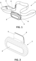
- Figure 1 shows an exemplary embodiment of a wearable device (1) according to the invention comprising a housing (2) and a flexible band or strap (3) for attaching the main housing to a part of a user's body, and a pair of electric and mechanic connectors or snap buttons (4) provided in the housing (2) for mechanically and electrically connecting the flexible band ends with the housing (2).
- the flexible band (3) is implemented as an elastic textile tape with female connectors at its ends to be coupled with the snap buttons (4).
- the flexible band (3) is fitted conventionally with at least one biosensor for measuring a vital-sign or physiological sign of the user, in a known manner, for example a pair of electrodes to measure heart rate.
- the electrodes are made of bioelectric silicone to capture the electrocardiogram signal and extract the heart rate, and they have sufficient conductivity to obtain a quality heart rate signal and are resistant to continuous use and washing.
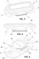
- the device (1) includes a consumable component (5) configured to be manually attached and detached from the housing (2), and having a contact surface (6) provided to be in contact with the user's skin when the consumable component (5) is coupled with the housing (2), and the housing (2) is attached to a user's body by means of the flexible band (3).
- the housing (2) is formed by two couplable parts, a base (2a) and a cover (2b) that configure a space when they are coupled within which an electronic circuit (7) is enclosed.
- This electronic circuit (7) implements the processing unit, sensors instrumentation, battery management, data processing and communication module for the wireless transmission of data processed by the processing unit.
- the housing (2) in particular the base (2a) has a recess or cavity (8) for receiving a battery (9) for supplying power to the electronic circuit (7), and a lid (10) for closing and opening the cavity (8).
- the consumable component (5) is generally a flat body, and the housing (2) and the consumable component (5) are configured, such that the consumable component (5) is couplable with the housing (2) by moving the consumable component (5) on a plane coplanar to the generally flat back surface (19) of the housing (2).
- the consumable component (5) is placed over lid (10) when is fully attached to the housing (2), and the lid (10) can only be accessed when the consumable component (5) is taken out from the housing (2).
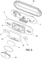
- a set of electric connectors (12) are provided at the back surface (13) of the base (2a) of the housing (2), in order to electrically connect the sensors fitted in the consumable component (5) with the processing unit (7).
- These connectors (12) are known spring-biased connectors, that stablish electric contact with corresponding electric pads (17) (provided in the consumable component (5), in a known manner when this is coupled with the housing (2).
- the consumable component (5) can be mechanically and electrically coupled and uncoupled from the housing (2), in a quick and intuitive manner for a user, while ensuring functionality and good electrical connection with the housing (2).
- the housing (2) has a back surface (13) provided with a pair of guides (15) opposite each other, in a way that a space or pocket is formed in between the guides (15) for receiving the consumable component (5) therein.
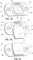
- the consumable component (5) has a pair of sides wings (16), dimensioned and configured to fit in the space formed in between the guides (15), such that the consumable component (5) is attachable to the housing (2) by inserting its side wings (16) respectively in the guides (15), and by moving the consumable component on the back surface (13) of the housing (2), as represented in the sequence of Figures 7A, 7B, and 7C .
- the pair of guides (15) also comprises the set of electric connectors (12), and as the pair of guides (15) provide an elevated surface, they can adequately comprise the set of electric connectors (12) such that they are at most at the same distance to the back surface (13) as the pair of guides (12).
- the set of electric connectors (12) stablish electric contact with corresponding electric pads (17) in a sealed way. Therefore, the electrical contact is established so sweat cannot affect the readings, as it is comprised between the surface of the consumable component (5) and the surface of the pair of guides (15), such that sweat cannot reach the electrical contact location.
- the mere connection being tight enough, provides the seal that avoids sweat coming into contact with the electrical connections between the set of electric connectors (12) and the corresponding electric pads (17).
- this allows for a simple integration system that does not require moving elements, nor coupling systems that may be prone to a wrong manual coupling, for example using magnets, that can still provide a sealed electrical connection between the housing (2) and the consumable component (5).
- This is essential for many application such as in sport use, wherein the amount of sweat and/or water present around the consumable component (5) is high.
- the surface of the consumable component (5) comprising the electric pads (17) and which is configured to contact the surface of the pair of guides (15) comprising the set of electric connectors (12), comprises an adhesive surface configured to further seal the coupling between the consumable component (5) and the housing (2).
- the housing (2) which is permanent can have a simple coupling integration surface, and the consumable component (5), which is renewed each time, comprises the additional sealing elements that are prone to wearing from its use. Therefore, the system is configured to ensure that the electrical connection between the housing (2) and the consumable component (5) will be always sealed. This is of special importance in some environments, wherein there is little to no space to seal error, such as in aquatic environments.
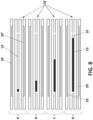
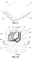
- the consumable component (5) has a sweat volume sensor (18) represented schematically in Figure 8 , which comprises a microfluidic circuit or a microfluidic reservoir (19), fluidly communicated with a sensing chamber (21) and arranged downstream the sensing chamber (21), such that sweat would enter the inlet (11), and flow along the microfluidic channel (22) and the sensing chamber (21) to gradually fill the reservoir (19), as more clearly represented in Figure 10 .
- a sweat volume sensor (18) represented schematically in Figure 8 , which comprises a microfluidic circuit or a microfluidic reservoir (19), fluidly communicated with a sensing chamber (21) and arranged downstream the sensing chamber (21), such that sweat would enter the inlet (11), and flow along the microfluidic channel (22) and the sensing chamber (21) to gradually fill the reservoir (19), as more clearly represented in Figure 10 .
- the sweat volume sensor (18) comprises a pair of electrodes (20,20') and the microfluidic reservoir (19) arranged in between the two electrodes, such that a capacitance value between the two electrodes is variable depending on the amount of sweat in the reservoir.
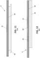
- the consumable component (5) can be manufactured as a stack of layers of plastic materials where the microfluidic channels and sensing chamber are formed by laser cutting or die cutting.
- the integrated sensors are electrochemical in nature, and therefore require electrodes that are fabricated by screen printing.
Landscapes
- Health & Medical Sciences (AREA)
- Life Sciences & Earth Sciences (AREA)
- Physics & Mathematics (AREA)
- Molecular Biology (AREA)
- Animal Behavior & Ethology (AREA)
- Biomedical Technology (AREA)
- Heart & Thoracic Surgery (AREA)
- Medical Informatics (AREA)
- Pathology (AREA)
- Surgery (AREA)
- Engineering & Computer Science (AREA)
- General Health & Medical Sciences (AREA)
- Public Health (AREA)
- Veterinary Medicine (AREA)
- Biophysics (AREA)
- Optics & Photonics (AREA)
- Hematology (AREA)
- Measuring And Recording Apparatus For Diagnosis (AREA)
- Measurement Of The Respiration, Hearing Ability, Form, And Blood Characteristics Of Living Organisms (AREA)
Claims (13)
- Tragbare Vorrichtung (1) zur kontinuierlichen Überwachung von Gesundheitsparametern eines Benutzers, umfassend:ein Gehäuse (2), welches eine Vorderfläche und eine Hinterfläche (13), und eine darin eingeschlossene Verarbeitungseinheit aufweist,Mittel (3) zum Befestigen des Gehäuses (2) an einem Teil des Körpers des Benutzers,eine Verbrauchskomponente (5), welche dazu ausgebildet ist, manuell mit dem Gehäuse (2) gekoppelt und entkoppelt zu werden, und welche eine Kontaktfläche (6) aufweist, welche dazu vorgesehen ist, der Haut des Benutzers in Kontakt mit zu sein, wenn die Verbrauchskomponente (5) mit dem Gehäuse (2) wirksam gekoppelt ist und das Gehäuse (2) an einem Teil des Körpers des Benutzers befestigt ist, undwobei die Verbrauchskomponente (5) Folgendes umfasst:einen Schweißsammeleinlass (11), welcher in der Kontaktfläche (6) der Verbrauchskomponente gebildet ist, um Schweiß zu sammeln, wenn die Vorrichtung (1) vom Benutzer getragen wird,mindestens einen Sensor zum Messen eines Schweißbiomarkers,einen mikrofluidischen Kanal (22) zum Fördern des gesammelten Schweißes vom Einlass (11) zum Schweißsensor,dadurch gekennzeichnet, dass die tragbare Vorrichtung (1) zusätzlich Folgendes umfasst:elektrische Anschlussmittel (12) zum elektrischen Anschließen des Sensors an die Verarbeitungseinheit, wenn die Verbrauchskomponente (5) mit dem Gehäuse (2) wirksam gekoppelt ist,wobei die Verarbeitungseinheit dazu angepasst ist, vom Sensor bereitgestellte Daten zu verarbeiten,wobei das Gehäuse (2) ein Paar einander gegenüberliegende Führungen (15) aufweist, und wobei die Verbrauchskomponente (5) ein Paar Seitenflügel (16) aufweist, und wobei das Gehäuse (2) und der Verbrauchsteil so ausgebildet sind, dass die Verbrauchskomponente (5) mit dem Gehäuse (2) koppelbar ist, indem dessen Seitenflügel (16) jeweils in die Führungen (15) eingesetzt werden und indem die Verbrauchskomponente (5) auf der Hinterfläche (13) des Gehäuses (2) bewegt wird,wobei die elektrischen Anschlussmittel (12) innerhalb von den Kopplungsflächen des Paares Führungen (15) und der Verbrauchskomponente (5) umfasst sind,wobei die Kopplungsflächen des Paares Führungen (15) und die Verbrauchskomponente (5) dazu ausgebildet sind, um sich auf abgedichtete Weise wirksam zu koppeln, so dass sie den elektrischen Anschluss abdichten undwobei die Fläche der Verbrauchskomponente (5), welche dazu ausgebildet ist, die Fläche des Paares Führungen (15), welche die elektrischen Anschlussmittel (12) umfassen, eine Haftfläche umfasst, welche dazu ausgebildet ist, die Kopplung zusätzlich abzudichten.
- Tragbare Vorrichtung (1) nach einem der vorhergehenden Ansprüche, wobei ein Teil der Hinterfläche (13) des Gehäuses (2) im Allgemeinen flach ist, und wobei die Verbrauchskomponente (5) mit dem Gehäuse (2) koppelbar und entkoppelbar ist, indem die Verbrauchskomponente (5) auf einer Ebene parallel zum genannten im Allgemeinen flachen Teil der Hinterfläche (13) oder auf einer Ebene komplanar mit der flachen Fläche bewegt wird.
- Tragbare Vorrichtung (1) nach einem der vorhergehenden Ansprüche, wobei die Verbrauchskomponente (5) im Allgemeinen ein flacher Körper ist.
- Tragbare Vorrichtung (1) nach einem der vorhergehenden Ansprüche, wobei die Mittel (3) zum Befestigen des Hauptgehäuses (2) an einem Teil des Körpers eines Benutzers einen flexiblen Streifen umfasst, welcher zwei Enden aufweist, welche jeweils mit dem Gehäuse (2) koppelbar sind.
- Tragbare Vorrichtung (1) nach einem der Ansprüche 1 bis 3, wobei die Mittel (3) zum Befestigen des Hauptgehäuses (2) an einem Teil des Körpers eines Benutzers eine Haftfläche umfasst, welche dafür geeignet ist, auf der Haut eines Benutzers angehaftet zu werden, und wobei die Haftfläche vorzugsweise auf der Kontaktfläche (6) der Verbrauchskomponente vorgesehen ist.
- Tragbare Vorrichtung (1) nach einem der vorhergehenden Ansprüche, wobei das Gehäuse (2) eine Aushöhlung (8) an dessen Hinterfläche (13), um eine Batterie (9) aufzunehmen, um die Verarbeitungseinheit mit Strom zu versorgen, und einen Deckel (10) zum Schließen der Aushöhlung (8) und zum Einschließen der Batterie (9) darin, aufweist, und wobei die Vorrichtung (1) so ausgebildet ist, dass die Verbrauchskomponente (5) mit dem Deckel (10) überlappt ist, wenn die Verbrauchskomponente (5) mit dem Gehäuse (2) wirksam gekoppelt ist.
- Tragbare Vorrichtung (1) nach den Ansprüchen 4 oder 6, wenn sie von Anspruch 4 abhängt, wobei das Gehäuse (2) mit einem Paar elektrischer Verbinder (12) versehen ist, und jedes Ende des flexiblen Streifens mit metallischen Verbindern ausgerüstet ist, um den flexiblen Streifen und den Biosensor mit dem Paar elektrischer Verbinder (12) des Gehäuses (2) mechanisch und elektrisch zu verbinden.
- Tragbare Vorrichtung (1) nach Anspruch 4, wobei der flexible Streifen mit mindestens einem Biosensor versehen ist, welcher dazu angeordnet ist, ein Vitalzeichen oder physiologisches Zeichen des Benutzers zu messen, wenn die Vorrichtung (1) vom Benutzer getragen wird, und wobei der Biosensor aus der folgenden Liste ausgewählt wird: einem Herzfrequenzsensor, einem Atemfrequenzsensor, einem Blutdrucksensor, einem Körpertemperatursensor und einem Sauerstoffsättigungssensor.
- Tragbare Vorrichtung (1) nach einem der vorhergehenden Ansprüche, wobei die Verbrauchskomponente (5) zusätzlich einen Schweißvolumensensor (18) zum Messen des Volumens des gesammelten Schweißes umfasst, und wobei die Verarbeitungseinheit dazu angepasst ist, Daten, welche vom Schweißsensor, dem Vitalzeichenbiosensor und der Schweißvolumenmessvorrichtung bereitgestellt werden, zu empfangen und zu verarbeiten.
- Tragbare Vorrichtung (1) nach einem der vorhergehenden Ansprüche, zusätzlich umfassend ein Kommunikationsmodul, welches im Gehäuse (2) eingeschlossen ist und für die drahtlose Übertragung von Daten angepasst ist, welche von der Verarbeitungseinheit verarbeitet werden.
- Tragbare Vorrichtung (1) nach Anspruch 9, wobei der Schweißsensor ein Schweißlaktatsensor ist, und der Vitalzeichensensor ein Herzfrequenzsensor ist, und wobei die Verarbeitungseinheit zusätzlich dazu angepasst ist, vorzugsweise mittels Algorithmen für maschinelles Lernen, eine Blutlaktatkonzentration zu berechnen oder zu schätzen, basierend auf den Daten, welche von Folgenden bereitgestellt werden: dem Schweißlaktatsensor, dem Schweißvolumensensor (18) und dem Herzfrequenzsensor.
- Tragbare Vorrichtung (1) nach einem der vorhergehenden Ansprüche, zusätzlich umfassend eine Erfassungskammer (21) und mindestens einen der folgenden Sensoren: einen Schweißlaktatsensor, einen Schweißleitfähigkeitssensor, einen Metabolitsensor, Ionensensoren, einen Aminosäuresensor, und, in der Erfassungskammer (21) platziert, und wobei der mikrofluidische Kanal (22) den Schweißeinlass (11) mit der Erfassungskammer (21) kommuniziert.
- Tragbare Vorrichtung (1) nach einem der vorhergehenden Ansprüche, wobei der Schweißvolumensensor (18) ein Paar Elektroden (20, 20') und einen mikrofluidischen Vorrat (19) zwischen dem Paar Elektroden (20, 20'), und fluidisch mit der Erfassungskammer (21) kommuniziert und stromabwärts der Erfassungskammer (21) angeordnet umfasst, sodass ein Kapazitätswert zwischen den beiden Elektroden (20, 20') in Abhängigkeit von der Schweißmenge im Vorrat (19) variabel ist.
Applications Claiming Priority (2)
| Application Number | Priority Date | Filing Date | Title |
|---|---|---|---|
| EP21383241.3A EP4205647A1 (de) | 2021-12-30 | 2021-12-30 | Tragbare vorrichtung zur kontinuierlichen überwachung von gesundheitsparametern |
| PCT/EP2022/088083 WO2023126524A1 (en) | 2021-12-30 | 2022-12-30 | Integration system of sensing consumables for wearable devices |
Publications (3)
| Publication Number | Publication Date |
|---|---|
| EP4447796A1 EP4447796A1 (de) | 2024-10-23 |
| EP4447796B1 true EP4447796B1 (de) | 2025-06-04 |
| EP4447796C0 EP4447796C0 (de) | 2025-06-04 |
Family
ID=79602148
Family Applications (2)
| Application Number | Title | Priority Date | Filing Date |
|---|---|---|---|
| EP21383241.3A Withdrawn EP4205647A1 (de) | 2021-12-30 | 2021-12-30 | Tragbare vorrichtung zur kontinuierlichen überwachung von gesundheitsparametern |
| EP22844557.3A Active EP4447796B1 (de) | 2021-12-30 | 2022-12-30 | Tragbare vorrichtung zur kontinuierlichen überwachung von gesundheitsparametern |
Family Applications Before (1)
| Application Number | Title | Priority Date | Filing Date |
|---|---|---|---|
| EP21383241.3A Withdrawn EP4205647A1 (de) | 2021-12-30 | 2021-12-30 | Tragbare vorrichtung zur kontinuierlichen überwachung von gesundheitsparametern |
Country Status (13)
| Country | Link |
|---|---|
| US (1) | US20250107727A1 (de) |
| EP (2) | EP4205647A1 (de) |
| JP (1) | JP2025501328A (de) |
| KR (1) | KR20240129020A (de) |
| CN (2) | CN118785847A (de) |
| AU (1) | AU2022426661A1 (de) |
| CA (1) | CA3245075A1 (de) |
| ES (1) | ES3037166T3 (de) |
| HU (1) | HUE072509T2 (de) |
| MX (1) | MX2024008239A (de) |
| PL (1) | PL4447796T3 (de) |
| WO (1) | WO2023126524A1 (de) |
| ZA (1) | ZA202405107B (de) |
Families Citing this family (1)
| Publication number | Priority date | Publication date | Assignee | Title |
|---|---|---|---|---|
| GB2635501A (en) * | 2023-11-10 | 2025-05-21 | Kuartismed Medikal Ltd Sti | Body sensor and bottle sensor and related systems |
Family Cites Families (8)
| Publication number | Priority date | Publication date | Assignee | Title |
|---|---|---|---|---|
| CN103220965A (zh) * | 2010-11-16 | 2013-07-24 | 泰尔茂株式会社 | 传感器系统以及传感器系统的使用方法 |
| US10874335B2 (en) * | 2015-03-25 | 2020-12-29 | Samsung Electronics Co., Ltd | Wearable electronic device |
| US10779420B2 (en) * | 2016-06-03 | 2020-09-15 | Crestron Electronics, Inc. | Coupling system for joining electronic equipment housings together in a rack system |
| WO2018067412A1 (en) * | 2016-09-29 | 2018-04-12 | General Electric Company | Method and systems for a sensor patch with embedded microfluidics for monitoring of fluid biomarkers |
| JP7093989B2 (ja) * | 2018-01-30 | 2022-07-01 | ライフケア技研株式会社 | 発汗量測定装置 |
| WO2019204565A1 (en) * | 2018-04-19 | 2019-10-24 | The Regents Of The University Of California | Low cost, transferrable and thermally stable sensor array patterned on conductive substrate for biofluid analysis |
| EP3946017A4 (de) * | 2019-03-31 | 2022-12-07 | Emfit Corp. | Wearable-sensor und gesundheitsverwaltungssystem mit einem wearable-sensor |
| US20200397315A1 (en) * | 2019-06-19 | 2020-12-24 | Epicore Biosystems, Inc. | Wearable fluidic device and system with integrated electronics |
-
2021
- 2021-12-30 EP EP21383241.3A patent/EP4205647A1/de not_active Withdrawn
-
2022
- 2022-12-30 EP EP22844557.3A patent/EP4447796B1/de active Active
- 2022-12-30 JP JP2024540064A patent/JP2025501328A/ja active Pending
- 2022-12-30 MX MX2024008239A patent/MX2024008239A/es unknown
- 2022-12-30 PL PL22844557.3T patent/PL4447796T3/pl unknown
- 2022-12-30 KR KR1020247025629A patent/KR20240129020A/ko active Pending
- 2022-12-30 HU HUE22844557A patent/HUE072509T2/hu unknown
- 2022-12-30 CN CN202280092807.5A patent/CN118785847A/zh active Pending
- 2022-12-30 US US18/725,532 patent/US20250107727A1/en active Pending
- 2022-12-30 CA CA3245075A patent/CA3245075A1/en active Pending
- 2022-12-30 CN CN202280092808.XA patent/CN118785848A/zh active Pending
- 2022-12-30 ES ES22844557T patent/ES3037166T3/es active Active
- 2022-12-30 AU AU2022426661A patent/AU2022426661A1/en active Pending
- 2022-12-30 WO PCT/EP2022/088083 patent/WO2023126524A1/en not_active Ceased
-
2024
- 2024-06-28 ZA ZA2024/05107A patent/ZA202405107B/en unknown
Also Published As
| Publication number | Publication date |
|---|---|
| ES3037166T3 (en) | 2025-09-29 |
| PL4447796T3 (pl) | 2025-10-20 |
| US20250107727A1 (en) | 2025-04-03 |
| ZA202405107B (en) | 2025-12-17 |
| CN118785847A (zh) | 2024-10-15 |
| JP2025501328A (ja) | 2025-01-17 |
| EP4205647A1 (de) | 2023-07-05 |
| KR20240129020A (ko) | 2024-08-27 |
| EP4447796A1 (de) | 2024-10-23 |
| WO2023126524A1 (en) | 2023-07-06 |
| MX2024008239A (es) | 2024-09-18 |
| CA3245075A1 (en) | 2023-07-06 |
| HUE072509T2 (hu) | 2025-11-28 |
| AU2022426661A1 (en) | 2024-07-25 |
| CN118785848A (zh) | 2024-10-15 |
| EP4447796C0 (de) | 2025-06-04 |
Similar Documents
| Publication | Publication Date | Title |
|---|---|---|
| US10813575B2 (en) | Dynamic blood glucose data acquiring device and host | |
| US10993661B1 (en) | Wireless charging of a wrist-mounted sensor platform | |
| CA3053362C (en) | Body-wearable medical device | |
| CN212346544U (zh) | 可穿戴感测设备 | |
| CN101268932B (zh) | 用于分析物浓度体内测量的系统 | |
| US20090062670A1 (en) | Heart monitoring body patch and system | |
| JP2015534495A (ja) | 監視デバイス | |
| JP7483081B2 (ja) | 医療用センサシステム、特に、連続グルコースモニタリングシステム | |
| WO2017037191A1 (en) | Kit for determining an analyte concentration | |
| CN113164104B (zh) | 多位置囊状部 | |
| EP4447796B1 (de) | Tragbare vorrichtung zur kontinuierlichen überwachung von gesundheitsparametern | |
| US20210330263A1 (en) | System for detecting biosignals | |
| CA3245073A1 (en) | PORTABLE DEVICE FOR CONTINUOUS MONITORING OF HEALTH PARAMETERS | |
| KR101097238B1 (ko) | 혈당 측정 패치 및 이를 이용한 혈당 측정 장치 | |
| CN213030630U (zh) | 穿戴式采集设备及穿戴式采集系统 | |
| KR102471204B1 (ko) | 인체 신호 검출 헤드셋 장치 | |
| EP4205644A1 (de) | Tragbare vorrichtung zur kontinuierlichen überwachung von gesundheitsparametern | |
| CN220546268U (zh) | 一种患者监测手环 | |
| CN215455877U (zh) | 基于物联网的身体指标监测腕带 | |
| EP4512310A1 (de) | Mikronadelintegrierte interstitielle flüssigkeitsbiomarkersensorsysteme und verfahren dafür | |
| JPWO2023126524A5 (de) |
Legal Events
| Date | Code | Title | Description |
|---|---|---|---|
| STAA | Information on the status of an ep patent application or granted ep patent |
Free format text: STATUS: UNKNOWN |
|
| STAA | Information on the status of an ep patent application or granted ep patent |
Free format text: STATUS: THE INTERNATIONAL PUBLICATION HAS BEEN MADE |
|
| PUAI | Public reference made under article 153(3) epc to a published international application that has entered the european phase |
Free format text: ORIGINAL CODE: 0009012 |
|
| STAA | Information on the status of an ep patent application or granted ep patent |
Free format text: STATUS: REQUEST FOR EXAMINATION WAS MADE |
|
| 17P | Request for examination filed |
Effective date: 20240716 |
|
| AK | Designated contracting states |
Kind code of ref document: A1 Designated state(s): AL AT BE BG CH CY CZ DE DK EE ES FI FR GB GR HR HU IE IS IT LI LT LU LV MC ME MK MT NL NO PL PT RO RS SE SI SK SM TR |
|
| GRAP | Despatch of communication of intention to grant a patent |
Free format text: ORIGINAL CODE: EPIDOSNIGR1 |
|
| STAA | Information on the status of an ep patent application or granted ep patent |
Free format text: STATUS: GRANT OF PATENT IS INTENDED |
|
| DAV | Request for validation of the european patent (deleted) | ||
| DAX | Request for extension of the european patent (deleted) | ||
| GRAS | Grant fee paid |
Free format text: ORIGINAL CODE: EPIDOSNIGR3 |
|
| INTG | Intention to grant announced |
Effective date: 20250328 |
|
| GRAA | (expected) grant |
Free format text: ORIGINAL CODE: 0009210 |
|
| STAA | Information on the status of an ep patent application or granted ep patent |
Free format text: STATUS: THE PATENT HAS BEEN GRANTED |
|
| REG | Reference to a national code |
Ref country code: HK Ref legal event code: DE Ref document number: 40117813 Country of ref document: HK |
|
| AK | Designated contracting states |
Kind code of ref document: B1 Designated state(s): AL AT BE BG CH CY CZ DE DK EE ES FI FR GB GR HR HU IE IS IT LI LT LU LV MC ME MK MT NL NO PL PT RO RS SE SI SK SM TR |
|
| REG | Reference to a national code |
Ref country code: GB Ref legal event code: FG4D |
|
| REG | Reference to a national code |
Ref country code: CH Ref legal event code: EP |
|
| REG | Reference to a national code |
Ref country code: DE Ref legal event code: R096 Ref document number: 602022015655 Country of ref document: DE |
|
| REG | Reference to a national code |
Ref country code: IE Ref legal event code: FG4D |
|
| U01 | Request for unitary effect filed |
Effective date: 20250703 |
|
| U07 | Unitary effect registered |
Designated state(s): AT BE BG DE DK EE FI FR IT LT LU LV MT NL PT RO SE SI Effective date: 20250710 |
|
| REG | Reference to a national code |
Ref country code: ES Ref legal event code: FG2A Ref document number: 3037166 Country of ref document: ES Kind code of ref document: T3 Effective date: 20250929 |
|
| PG25 | Lapsed in a contracting state [announced via postgrant information from national office to epo] |
Ref country code: GR Free format text: LAPSE BECAUSE OF FAILURE TO SUBMIT A TRANSLATION OF THE DESCRIPTION OR TO PAY THE FEE WITHIN THE PRESCRIBED TIME-LIMIT Effective date: 20250905 |
|
| PG25 | Lapsed in a contracting state [announced via postgrant information from national office to epo] |
Ref country code: HR Free format text: LAPSE BECAUSE OF FAILURE TO SUBMIT A TRANSLATION OF THE DESCRIPTION OR TO PAY THE FEE WITHIN THE PRESCRIBED TIME-LIMIT Effective date: 20250604 |
|
| PG25 | Lapsed in a contracting state [announced via postgrant information from national office to epo] |
Ref country code: RS Free format text: LAPSE BECAUSE OF FAILURE TO SUBMIT A TRANSLATION OF THE DESCRIPTION OR TO PAY THE FEE WITHIN THE PRESCRIBED TIME-LIMIT Effective date: 20250904 |
|
| REG | Reference to a national code |
Ref country code: HU Ref legal event code: AG4A Ref document number: E072509 Country of ref document: HU |
|
| REG | Reference to a national code |
Ref country code: CH Ref legal event code: U11 Free format text: ST27 STATUS EVENT CODE: U-0-0-U10-U11 (AS PROVIDED BY THE NATIONAL OFFICE) Effective date: 20260101 |
|
| PG25 | Lapsed in a contracting state [announced via postgrant information from national office to epo] |
Ref country code: IS Free format text: LAPSE BECAUSE OF FAILURE TO SUBMIT A TRANSLATION OF THE DESCRIPTION OR TO PAY THE FEE WITHIN THE PRESCRIBED TIME-LIMIT Effective date: 20251004 |
|
| PG25 | Lapsed in a contracting state [announced via postgrant information from national office to epo] |
Ref country code: SM Free format text: LAPSE BECAUSE OF FAILURE TO SUBMIT A TRANSLATION OF THE DESCRIPTION OR TO PAY THE FEE WITHIN THE PRESCRIBED TIME-LIMIT Effective date: 20250604 |
|
| PGFP | Annual fee paid to national office [announced via postgrant information from national office to epo] |
Ref country code: HU Payment date: 20251218 Year of fee payment: 4 |
|
| PGFP | Annual fee paid to national office [announced via postgrant information from national office to epo] |
Ref country code: TR Payment date: 20251212 Year of fee payment: 4 |
|
| PG25 | Lapsed in a contracting state [announced via postgrant information from national office to epo] |
Ref country code: CZ Free format text: LAPSE BECAUSE OF FAILURE TO SUBMIT A TRANSLATION OF THE DESCRIPTION OR TO PAY THE FEE WITHIN THE PRESCRIBED TIME-LIMIT Effective date: 20250604 |
|
| PGFP | Annual fee paid to national office [announced via postgrant information from national office to epo] |
Ref country code: IE Payment date: 20251212 Year of fee payment: 4 |
|
| PGFP | Annual fee paid to national office [announced via postgrant information from national office to epo] |
Ref country code: PL Payment date: 20251212 Year of fee payment: 4 |
|
| PG25 | Lapsed in a contracting state [announced via postgrant information from national office to epo] |
Ref country code: SK Free format text: LAPSE BECAUSE OF FAILURE TO SUBMIT A TRANSLATION OF THE DESCRIPTION OR TO PAY THE FEE WITHIN THE PRESCRIBED TIME-LIMIT Effective date: 20250604 |
|
| U20 | Renewal fee for the european patent with unitary effect paid |
Year of fee payment: 4 Effective date: 20251229 |