EP4447488A1 - Piezoelektrische sensoreinheit, piezoelektrisches mikrofon und endgerät - Google Patents
Piezoelektrische sensoreinheit, piezoelektrisches mikrofon und endgerät Download PDFInfo
- Publication number
- EP4447488A1 EP4447488A1 EP21969497.3A EP21969497A EP4447488A1 EP 4447488 A1 EP4447488 A1 EP 4447488A1 EP 21969497 A EP21969497 A EP 21969497A EP 4447488 A1 EP4447488 A1 EP 4447488A1
- Authority
- EP
- European Patent Office
- Prior art keywords
- cantilever
- piezoelectric
- sensing unit
- piezoelectric sensing
- unit according
- Prior art date
- Legal status (The legal status is an assumption and is not a legal conclusion. Google has not performed a legal analysis and makes no representation as to the accuracy of the status listed.)
- Pending
Links
Images


Classifications
-
- H—ELECTRICITY
- H04—ELECTRIC COMMUNICATION TECHNIQUE
- H04R—LOUDSPEAKERS, MICROPHONES, GRAMOPHONE PICK-UPS OR LIKE ACOUSTIC ELECTROMECHANICAL TRANSDUCERS; ELECTRIC HEARING AIDS; PUBLIC ADDRESS SYSTEMS
- H04R17/00—Piezoelectric transducers; Electrostrictive transducers
- H04R17/02—Microphones
-
- H—ELECTRICITY
- H04—ELECTRIC COMMUNICATION TECHNIQUE
- H04R—LOUDSPEAKERS, MICROPHONES, GRAMOPHONE PICK-UPS OR LIKE ACOUSTIC ELECTROMECHANICAL TRANSDUCERS; ELECTRIC HEARING AIDS; PUBLIC ADDRESS SYSTEMS
- H04R1/00—Details of transducers, loudspeakers or microphones
- H04R1/02—Casings; Cabinets ; Supports therefor; Mountings therein
- H04R1/04—Structural association of microphone with electric circuitry therefor
-
- H—ELECTRICITY
- H04—ELECTRIC COMMUNICATION TECHNIQUE
- H04R—LOUDSPEAKERS, MICROPHONES, GRAMOPHONE PICK-UPS OR LIKE ACOUSTIC ELECTROMECHANICAL TRANSDUCERS; ELECTRIC HEARING AIDS; PUBLIC ADDRESS SYSTEMS
- H04R7/00—Diaphragms for electromechanical transducers; Cones
- H04R7/02—Diaphragms for electromechanical transducers; Cones characterised by the construction
- H04R7/04—Plane diaphragms
-
- H—ELECTRICITY
- H04—ELECTRIC COMMUNICATION TECHNIQUE
- H04R—LOUDSPEAKERS, MICROPHONES, GRAMOPHONE PICK-UPS OR LIKE ACOUSTIC ELECTROMECHANICAL TRANSDUCERS; ELECTRIC HEARING AIDS; PUBLIC ADDRESS SYSTEMS
- H04R2201/00—Details of transducers, loudspeakers or microphones covered by H04R1/00 but not provided for in any of its subgroups
- H04R2201/003—Mems transducers or their use
-
- H—ELECTRICITY
- H04—ELECTRIC COMMUNICATION TECHNIQUE
- H04R—LOUDSPEAKERS, MICROPHONES, GRAMOPHONE PICK-UPS OR LIKE ACOUSTIC ELECTROMECHANICAL TRANSDUCERS; ELECTRIC HEARING AIDS; PUBLIC ADDRESS SYSTEMS
- H04R2410/00—Microphones
- H04R2410/03—Reduction of intrinsic noise in microphones
Definitions
- This application relates to the field of microphone structure technologies, and in particular, to a piezoelectric sensing unit, a piezoelectric microphone, and a terminal.
- a microphone is a common sound capture device, and is configured to convert a sound signal into an electrical signal.
- Microphones are classified into a dynamic microphone, a ribbon microphone, an electret microphone (electret microphone, ECM), a micro-electromechanical system (Micro-electromechanical system, MEMS) capacitive microphone, and an MEMS piezoelectric microphone based on types.
- ECM electret microphone
- MEMS micro-electromechanical system
- MEMS piezoelectric microphone based on types.
- Most modern microphones are electret microphones and MEMS capacitive microphones. However, due to a process, the electret microphone is far less consistent in production and less stable in a temperature than the MEMS capacitive microphone. However, the MEMS capacitive microphone needs to use a charge pump to improve sensitivity, resulting in high power consumption.
- the MEMS piezoelectric microphone can convert sound pressure into a charge output by using positive piezoelectric effect of a piezoelectric material
- a piezoelectric microphone in the conventional technology, includes a base having a cavity.
- a cantilever is prepared in a region of the cavity of the base, and a piezoelectric material layer is prepared on the cantilever, to form a piezoelectric sensing unit of the piezoelectric microphone.
- the cantilever in the piezoelectric microphone usually extends from an edge of the cavity to a center of the cavity, or extends from a center of the cavity to an edge of the cavity, resulting in a short length of the cantilever.
- a relationship between a charge output of the microphone and pressure exerted on the cantilever has a strong correlation with a length of the cantilever. Therefore, in the conventional technology, the short length of the cantilever in the piezoelectric microphone results in poor charge output effect of the microphone.
- This application provides a piezoelectric sensing unit, a piezoelectric microphone, and a terminal, to improve a signal-to-noise ratio of the piezoelectric microphone and improve performance of the piezoelectric microphone.
- this application provides a piezoelectric sensing unit.
- the piezoelectric sensing unit includes a base, an auxiliary layer, a central film, a piezoelectric film, and a plurality of cantilevers.
- the base has a cavity extending in a first direction, the cavity forms a polygonal opening on a first surface of the base, and the polygonal opening has a first side and a second side that are adjacent to each other.
- the auxiliary layer is formed on the first surface of the base, the auxiliary layer includes a first auxiliary part, and the first auxiliary part is located in a region that is on the first surface and that is adjacent to the first side.
- the cantilevers are one-to-one connected to sides of the polygonal opening.
- the cantilever includes a first end part and a second end part, the first end part is connected to the first auxiliary part, and a connection point between the first end part and the first auxiliary part is located on a side that is of the first auxiliary part and that is close to the second side.
- the cantilever extends in an extension direction of the second side. In this case, in this solution, a length of the cantilever is long, to help improve a signal-to-noise ratio of a piezoelectric microphone.
- the central film is connected to the second end part of each of the cantilevers, and an orthographic projection of the polygonal opening on a first plane completely covers an orthographic projection of the central film on the first plane, where the first plane is perpendicular to the first direction.
- the central film is opposite to the cavity of the base. In this case, after a sound wave enters the cavity, the central film may be driven to vibrate, to drive the cantilever to swing.
- the piezoelectric film is disposed on a surface of the cantilever. Specifically, the piezoelectric film includes a piezoelectric material layer, a first electrode layer, and a second electrode layer, and the piezoelectric material layer is connected to the first electrode layer and the second electrode layer. In this case, the piezoelectric film may convert swing of the cantilever into an electrical signal.
- the cantilever includes a first edge and a second edge, and the first edge and the second edge are connected between the first end part and the second end part. At least one of the first edge and the second edge is parallel to the second side of the polygon.
- the central film and the cantilever may be of an integrated structure, to prepare the piezoelectric sensing unit. According to this solution, a process of preparing the piezoelectric sensing unit can be simplified, and reliability of a connection between the central film and the cantilever can be further improved.
- the central film may be provided with a hole. Certainly, a quantity of holes and a shape of the hole are not limited.
- the hole of the central film can release some sound pressure, to increase an acoustic overload point of the piezoelectric sensing unit.
- the central film and the cantilever may be located on a same plane, or the central film and the cantilever may be located on different planes, to dispose the central film and the cantilever.
- the central film and the cantilever may be located on different planes, the central film may be located on a side that is of the cantilever and that faces the base, and the central film is connected to the cantilever through the connection part.
- sensitivity of the piezoelectric sensing unit is high, and performance of the piezoelectric microphone having the piezoelectric sensing unit is also good.
- central film and the cantilever are disposed on different planes, at least a partial structure of the central film may overlap the cantilever. In this case, an area of the central film may be large, to increase effectively input sound pressure and improve performance of the piezoelectric microphone.
- connection part may specifically include a first connection part and a second connection part.
- the first connection part and the cantilever may be of an integrated structure, and the second connection part is connected to the first connection part and the central film.
- the first connection part may have a plurality of first connection holes, and the second connection part is connected to the first connection holes. In this way, reliability of the connection between the first connection part and the second connection part is improved.
- connection part may be further connected to the cantilever, so that the central film is connected to the cantilever.
- the cantilever may include at least one second connection hole, and the second connection part is connected to the second connection hole.
- a width of the cantilever in a direction perpendicular to the second side may be a first width.
- the first width gradually decreases from the first end part to the second end part.
- a width of a joint between the cantilever and the first auxiliary part is large, and therefore a stress near the first end part of the cantilever is large. This helps convert, into an electrical signal, vibration generated by a sound wave, and then improve signal conversion efficiency.
- the first width of the second end part is small.
- an area of the central film may be designed to be large. This can increase effectively input sound pressure and improve performance of the piezoelectric microphone.
- the first edge and/or the second edge of the cantilever are/is perpendicular to the first side connected to the cantilever. In other words, at least one of the first edge and the second edge is perpendicular to the first side. In this way, in this solution, the cantilever may be perpendicular to the first side, to reduce torque of a root part of the cantilever.
- the first side of an inner cavity of the base may have a groove or protrusion corresponding to the cantilever. It should be noted that the first side may have the groove, to help increase the length of the cantilever.
- An effective region of the piezoelectric film is located on a side that is of the cantilever and that is close to the first auxiliary part connected to the cantilever. Because a stress of a region in which the cantilever is connected to the first connection part is large, signal conversion efficiency can be improved, and performance of the piezoelectric microphone can be improved.
- the central film may further have an additional mass block.
- the additional mass block may enable a large swing amplitude of the central film when the central film receives sound pressure, to improve sensitivity of the piezoelectric sensing unit.
- lengths of the plurality of cantilevers in the piezoelectric sensing unit may be the same or may be different. This is not limited in this application. Lengths of the plurality of cantilevers are different. When the lengths of the plurality of cantilevers are different, the piezoelectric microphone may have different low-frequency resonant points, and low-frequency sensitivity is high. This can improve a voiceprint recognition capability.
- a material of the cantilever is not limited.
- the material of the cantilever may be different from that of the piezoelectric material layer, and the cantilever is merely used as a structure layer, and includes only one piezoelectric material layer.
- the piezoelectric sensing unit is a piezoelectric sensing unit in a unimorph (Unimorph) mode.
- a material of the cantilever may alternatively be the same as that of the piezoelectric material layer.
- the cantilever is also used as the piezoelectric material layer.
- the piezoelectric sensing unit is a piezoelectric sensing unit in a bimorph (Bimorph) mode.
- the auxiliary layer and the cantilever may be of an integrated structure, to prepare the piezoelectric microphone. This can facilitate preparation of the auxiliary layer and the cantilever to simplify a preparation process. In addition, reliability of a connection between the auxiliary layer and the cantilever is improved.
- this application further provides a piezoelectric microphone.
- the piezoelectric microphone includes a circuit board, a chip, and the piezoelectric sensing unit according to the first aspect.
- the foregoing chip is disposed on the circuit board, and the first electrode and the second electrode are connected to the chip, so that the piezoelectric sensing unit can process an electrical signal converted from a sound wave.
- the piezoelectric microphone further includes a housing, and the circuit board, the chip, and the piezoelectric sensing unit are disposed inside the housing.
- the housing may protect the circuit board, the chip, and the piezoelectric sensing unit inside, and may also shield interference.
- this application further provides a terminal.
- the terminal includes the piezoelectric microphone according to the second aspect.
- a sound reception effect of the terminal is good.
- a specific type of the terminal is not limited.
- the terminal may be a terminal that needs to record a sound, for example, a mobile phone, a headset, an intelligent device, a voice recorder, a hearing aid, a microphone, a voice control device, or a vehicle-mounted voice interaction device.
- 1 circuit board; 2: chip; 3: piezoelectric sensing unit; 31: base; 311: cavity; 312: first surface; 313: polygonal opening; 3131: first side; 3132: second side; 3133: groove; 32: cantilever; 321: first end part; 322: second end part; 323: first edge; 324: second edge; 325: second connection hole; 33: piezoelectric film; 331: piezoelectric material layer; 332: first electrode layer; 333: second electrode layer; 334: effective working region; 34: first electrode; 35: second electrode; 36: auxiliary layer; 361: first auxiliary part; 37: central film; 371: hole; 372: additional mass block; 38: connection part; 381: first connection part; 3811: first connection hole; 382: second connection part; 4: housing.
- embodiments of this application provide a piezoelectric sensing unit, a piezoelectric microphone, and a terminal.
- the following describes an application scenario of the piezoelectric sensing unit, the piezoelectric microphone, and the terminal.
- microphones are currently used in various terminals, to implement functions such as calling or sound control of the terminals. Types of the microphones also change gradually. Because an MEMS piezoelectric microphone has low power consumption, the MEMS piezoelectric microphone is an important research direction of a person skilled in the art.
- a cantilever in an existing piezoelectric microphone usually extends from an edge of a cavity to a center of the cavity, or extends from a center of a cavity to an edge of the cavity, resulting in a short length of the cantilever.
- a relationship between a charge output of the microphone and pressure exerted on the cantilever has a strong correlation with a length of the cantilever. Therefore, in the conventional technology, the short length of the cantilever in the piezoelectric microphone results in poor charge output effect of the microphone.
- the terminal includes a piezoelectric microphone, and the piezoelectric microphone is used for recording a sound.
- a specific type of the terminal is not limited.
- the terminal may be a terminal that needs to record a sound, for example, a mobile phone, a headset, an intelligent device, a voice recorder, a hearing aid, a microphone, a voice control device, or a vehicle-mounted voice interaction device.
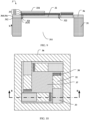
- FIG. 1 is a diagram of a structure of a piezoelectric microphone according to an embodiment of this application.
- the piezoelectric microphone in this embodiment of this application includes a circuit board 1, a chip 2, and a piezoelectric sensing unit 3.
- the chip 2 is disposed on the circuit board 1. Specifically, the chip 2 may be electrically connected to the circuit board 1.
- the piezoelectric sensing unit 3 includes a base 31 and a cantilever 32 and a piezoelectric film (which is not shown in the figure) that are formed on the base 31.
- the base 31 has a cavity 311, a first end part 321 of the cantilever 32 is connected to the base 31 and suspended on the cavity 311, and the piezoelectric film is disposed on a surface of the cantilever 32.
- the piezoelectric film can receive vibration of a sound wave and convert the vibration into an electrical signal.
- the piezoelectric film of the piezoelectric sensing unit 3 is electrically connected to the chip 2, so that the chip 2 can process the electrical signal generated after the piezoelectric sensing unit 3 receives the sound wave.
- the chip 2 performs processing like collection, amplification, and filtering on the electrical signal, and then may further output an analog signal or a digital signal.
- the sound wave may be converted into the electrical signal by using a positive piezoelectric feature of a piezoelectric material layer in the piezoelectric film, and no other driver needs to be configured. This helps reduce a size of the piezoelectric microphone, reduce power consumption of the piezoelectric microphone, and improve use duration of the piezoelectric microphone, and then improve use duration of a terminal having the piezoelectric microphone.
- the piezoelectric microphone may further include a housing 4.
- the circuit board 1, the chip 2, and the piezoelectric sensing unit 3 are disposed inside the housing 4.
- the housing 4 may shield an interference signal, and may protect components disposed inside the housing.
- the piezoelectric microphone in the embodiment shown in FIG. 1 is a piezoelectric microphone packaged with a bottom opening, and the piezoelectric microphone packaged with the bottom opening is suitable for a thin product.
- the piezoelectric sensing unit 3 and the chip 2 are separately installed on the circuit board 1, and there is an opening in a region that is of the circuit board 1 and that is opposite to the cavity 311 of the piezoelectric sensing unit 3, where the opening corresponds to a sound inlet. In this packaging manner, no opening needs to be disposed in the housing 4.
- FIG. 2 is a diagram of another structure of a piezoelectric microphone according to an embodiment of this application.
- the piezoelectric microphone in the embodiment shown in FIG. 2 is a piezoelectric microphone packaged with a top opening.
- the piezoelectric sensing unit 3 and the chip 2 are separately installed on the circuit board 1, but the circuit board 1 has no opening, the housing 4 has an opening, and the opening of the housing 4 is used as a sound inlet hole.
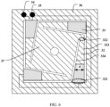
- FIG. 3 is a diagram of a top-view structure of a piezoelectric sensing unit according to an embodiment of this application.
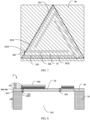
- FIG. 4 is a diagram of a lateral sectional-view structure of a piezoelectric sensing unit according to an embodiment of this application. Specifically, FIG. 4 is a diagram of a sectional-view structure at A-A in FIG. 3 .
- the piezoelectric sensing unit 3 includes a base 31, an auxiliary layer 36, a plurality of cantilevers 32, a central film 37, and a piezoelectric film 33.
- the base 31 is an overall support part of the piezoelectric sensing unit 3.
- the base 31 forms a cavity 311 extending in a first direction X, and the cavity 311 may form a cavity for sound transmission. It may be considered that the cavity 311 is of a tubular structure, has a side wall connected in a closed manner on a peripheral side, and has a first opening and a second opening that are opposite to each other. A direction of the first opening toward the second opening may be considered as the first direction X.
- the cavity 311 forms a polygonal opening 313 on a first surface 312 of the base 31, or the base 31 has a polygonal opening 313 on a first surface 312.
- the polygonal opening 313 is an opening of the cavity 311.
- the auxiliary layer 36 is formed on the first surface 312 of the base 31, and may be configured to connect to the plurality of cantilevers 32.
- the polygonal opening 313 includes a first side 3131 and a second side 3132 that are adjacent to each other, and the auxiliary layer 36 includes a first auxiliary part 361.
- the first auxiliary part 361 is located in a region that is of the first surface 312 of the base 31 and that is adjacent to the first side 3131.
- the first auxiliary part 361 is provided on the first surface 312 that is of the base 31 and that corresponds to the first side 3131.
- the plurality of cantilevers 32 one-to-one correspond to sides of the polygonal opening 313.
- the cantilever 32 includes a first end part 321 and a second end part 322 that are opposite to each other.
- the first end part 321 is connected to a side that is of the first auxiliary part 361 and that is close to the second side 3132, and the cantilever 32 extends in an extension direction of the second side 3132.
- the central film 37 is connected to the second end part 322 of each cantilever 32. In this case, the central film 37 vibrates when receiving a sound wave, to drive the cantilever 32 to vibrate.
- an orthographic projection of the polygonal opening 313 on a first plane completely covers an orthographic projection of the central film 37 on the first plane, where the first plane is perpendicular to the first direction X.
- the piezoelectric film 33 is disposed on a surface of the cantilever 32.
- the piezoelectric film 33 includes a piezoelectric material layer 331, a first electrode layer 332, and a second electrode layer 333, and the piezoelectric material layer 331 is connected to the first electrode layer 332 and the second electrode layer 333.
- the piezoelectric material layer 331 has a piezoelectric feature. When physical deformation occurs, a charge is generated, and an intensity of the charge is related to an intensity of the deformation. In this way, as the cantilever 32 vibrates, the piezoelectric material layer 331 generates a charge, and may transmit the charge through the first electrode layer 332 and the second electrode layer 333, to convert a sound signal into an electrical signal.
- the first end part 321 of the cantilever 32 is connected to the first auxiliary part 361 adjacent to the first side 3131, a specific connection point between the cantilever 32 and the first auxiliary part 361 is close to a direction of the second side 3132, and the cantilever 32 extends in the extension direction of the second side 3132.
- a maximum length of the cantilever 32 may be close to a length of the second side 3132.
- space of the opening of the cavity 311 can be fully used, so that a length of the cantilever 32 is long.
- the piezoelectric sensing unit 3 may be a piezoelectric sensing unit in a unimorph (Unimorph) mode, or may be a piezoelectric sensing unit in a bimorph (Bimorph) mode.
- OPT SNR ⁇ 10 Log (OPT)
- SNR cantilever signal-to-noise ratio
- ⁇ is a dielectric constant
- tan(9) is a dielectric loss
- d 31 is a piezoelectric constant
- w is a width of the cantilever 32
- L is a length of the cantilever 32
- t is a thickness of the cantilever 32
- q uni is a structure parameter ratio.
- each side of the polygonal opening 313 may be understood as the first side 3131 under different references.
- a region that is of the auxiliary layer 36 and that is adjacent to each side of the polygon opening also forms the first auxiliary part 361 in the case of the first side 3131.
- the auxiliary layer 36 connected to the cantilever 32 is the first auxiliary part 361
- a side of the polygon adjacent to the first auxiliary part 361 is the first side 3131.
- each side of the polygonal opening 313 may be formed as the first side 3131, and a part that is of the auxiliary layer 36 and that is opposite to the polygonal opening 313 may be the first auxiliary part 361.
- the piezoelectric sensing unit 3 may further include a first electrode 34 and a second electrode 35.
- the first electrode layer 332 of the piezoelectric film 33 of each cantilever 32 is connected to the first electrode 34
- the second electrode layer 333 of the piezoelectric film 33 of each cantilever 32 is connected to the second electrode 35.
- all first electrode layers 332 may be connected in series or in parallel
- all second electrode layers 333 may be connected in series or in parallel. This is not limited in this application.
- the first electrode layers and the second electrode layers may be designed based on an actual requirement of the piezoelectric microphone.
- the piezoelectric sensing unit 3 may be a piezoelectric sensing unit in a unimorph (Unimorph) mode, or may be a piezoelectric sensing unit in a bimorph (Bimorph) mode.
- the cantilever 32 is a base material, and a material of the cantilever 32 is different from a material of the piezoelectric material layer.
- the cantilever 32 may be made of a silicon-containing material.
- a material of the cantilever 32 is the same as that of the piezoelectric material layer.
- the cantilever is also used as the piezoelectric material layer.
- the cantilever 32 may alternatively be used as a base material, and two piezoelectric material layers are disposed on the surface of the cantilever, so that the piezoelectric sensing unit in the bimorph mode is formed.
- the cantilever 32 includes a first edge 323 and a second edge 324 that are opposite to each other, and the first edge 323 and the second edge 324 are separately connected between the first end part 321 and the second end part 322. At least one of the first edge 323 and the second edge 324 is parallel to the second side 3132 of the polygonal opening 313.
- the length of the cantilever 32 may be close to the length of the second side 3132.
- the length of the cantilever 32 may be longer, and a smaller area of the middle region of the polygonal opening 313 is occupied, so that an area of the central film 37 is large. This helps increase effectively input sound pressure.
- an area of the polygonal opening 313 can be fully used, so that performance of the piezoelectric microphone is improved.
- the first edge 323 may be parallel to the second edge 324. In this case, both the first edge 323 and the second edge 324 are parallel to the second side 3132.
- FIG. 5 and FIG. 6 are diagrams of other two top-view structures of the piezoelectric sensing unit.
- the first edge 323 may not be parallel to the second edge 324, and only the first edge 323 may be parallel to the second side 3132, but the second edge 324 may not be parallel to the second side 3132.
- a width of the cantilever 32 in a direction perpendicular to the second side 3132 is used as a first width d.
- the first width d may gradually increase from the first end part 321 to the second end part 322 of the cantilever 32.
- a width of a joint between the cantilever 32 and the first auxiliary part 361 is small, and therefore much space may be reserved for an adjacent cantilever 32. This helps increase the length of the cantilever 32, and then improve the OPT and the SNR.
- a width of the cantilever 32 in a direction perpendicular to the second side 3132 is used as a first width d.
- the first width d may gradually decrease from the first end part 321 to the second end part 322 of the cantilever 32.
- a width of a joint between the cantilever 32 and the first auxiliary part 361 is large. Because a stress near the first end part 321 of the cantilever 32 is large, in this embodiment, an area of a region with a large stress on the cantilever 32 may be large. This helps convert, into an electrical signal, vibration generated by a sound wave, and then improve signal conversion efficiency.
- the first width of the second end part 322 is small. In this case, an area of the central film 37 may be designed to be large. This can increase effectively input sound pressure and improve performance of the piezoelectric microphone.
- At least one of the first edge 323 and the second edge 324 of the cantilever 32 may be perpendicular to the first side 3131 connected to the cantilever 32, to dispose the cantilever 32.
- the cantilever 32 may be perpendicular to the first side 3131. In this way, in a vibration process of the cantilever 32, a torque phenomenon does not easily occur at a joint between the first end part 321 and the first auxiliary part 361. This helps generate an effective charge output.
- FIG. 7 is a diagram of another top-view structure of a piezoelectric sensing unit according to an embodiment of this application. It should be noted that, for ease of expressing features, FIG. 7 simplifies some features of the accompanying drawing, and shows only two layers of structures: the auxiliary layer 36 and the cantilever 32. As shown in FIG. 7 , the first side 3131 is not necessarily perpendicular to the second side 3132. In other words, the polygonal opening is not necessarily a square opening, or may be another polygonal opening like a triangular opening or a pentagonal opening. The polygonal opening of the piezoelectric sensing unit shown in FIG. 7 is a triangular opening.
- the first side 3131 may have a protrusion or groove 3133 corresponding to the cantilever 32.
- the cantilever 32 is connected to the first auxiliary part 361 corresponding to a location of the protrusion or groove 3133, and it is ensured that at least one of the first edge 323 and the second edge 324 is perpendicular to the first side 3131 connected to the cantilever 32.
- the first side 3131 may have the groove 3133. This helps increase the length of the cantilever 32.
- FIG. 8 is a diagram of another lateral sectional-view structure of a piezoelectric sensing unit according to an embodiment of this application.
- an effective working region 334 of the piezoelectric film 33 may be located on a side that is of the cantilever 32 and that is close to the first auxiliary part 361 connected to the cantilever 32, to prepare the piezoelectric film 33 on the surface of the cantilever 32.
- the effective working region 334 of the piezoelectric film 33 is located near a root of the cantilever 32.
- the effective working region 334 is a region in which the piezoelectric film 33 can convert deformation of the piezoelectric material layer 331 into an electrical signal.
- the effective working region 334 may be a region in which the piezoelectric film 33 have the first electrode layer 332, the piezoelectric material layer 331, and the second electrode layer 333.
- the piezoelectric film 33 may be overall located on a side that is of the cantilever 32 and that is close to the first auxiliary part 361 connected to the cantilever 32, as shown in FIG. 6 and FIG. 8 .
- FIG. 9 is a diagram of another lateral sectional-view structure of a piezoelectric sensing unit according to an embodiment of this application. As shown in FIG. 9 , in another embodiment, only at least one of the first electrode layer 332 and the second electrode layer 333 may be disposed on a side that is of the cantilever 32 and that is close to the first auxiliary part 361 connected to the cantilever 32, and the piezoelectric material layer 331 covers the entire cantilever 32. In this solution, a manufacturing process of the piezoelectric film 33 can be simplified.
- the piezoelectric film 33 may alternatively completely cover the entire cantilever 32. This is not limited in this application.
- a specific manner of preparing the first electrode layer 332 and the second electrode layer 333 is not limited.
- the first electrode layer 332 and the second electrode layer 333 may be disposed on surfaces on two sides of the piezoelectric material layer 331.
- the first electrode layer 332, the piezoelectric material layer 331, and the second electrode layer 333 are stacked in sequence.
- the first electrode layer 332 and the second electrode layer 333 form interdigital electrodes.
- the first electrode layer 332 and the second electrode layer 333 may be located on a surface on a same side of the piezoelectric material layer 331.
- the first electrode layer 332, the piezoelectric material layer 331, and the second electrode layer 333 may be stacked in sequence, to indicate that the first electrode layer 332 is of an interdigital structure, and the second electrode layer 333 is of an interdigital structure. This is not limited in this application.
- the auxiliary layer 36 and the cantilever 32 may be of an integrated structure, to prepare the auxiliary layer 36 and the cantilever 32.
- the solution facilitates preparation of the auxiliary layer 36 and the cantilever 32, and the auxiliary layer 36 and the cantilever 32 may be formed by using a one-time process, so that a preparation process is simplified.
- a connection between the cantilever 32 and the auxiliary layer 36 may be reliable, so that structural reliability of the piezoelectric sensing unit 3 is improved.
- the central film 37 and the cantilever 32 may alternatively be of an integrated structure.
- the solution facilitates preparation of the central film 37 and the cantilever 32, and the central film 37 and the cantilever 32 may be formed by using a one-time process, so that a preparation process is simplified.
- a connection between the cantilever 32 and the central film 37 may be reliable, so that structural reliability of the piezoelectric sensing unit 3 is improved.
- the central film 37, the cantilever 32, and the auxiliary layer 36 may be of an integrated structure.
- the central film 37, the cantilever 32, and the auxiliary layer 36 may be formed by using a one-time process, so that the process is simplified to a large extent.
- the central film 37 may have a hole 371.
- a specific quantity of holes 371 is not limited.
- the central film 37 may have one hole 371.
- the central film 37 may alternatively have two or more holes 371.
- a shape of the hole is not limited.
- the hole may be a round hole, a square hole, or the like. In this solution, the hole can release some sound pressure, to increase an acoustic overload point (AOP) of the piezoelectric sensing unit.
- AOP acoustic overload point
- the central film 37 is located on a side that is of the cantilever 32 and that faces the base 31, and the central film 37 is connected to the cantilever 32 through a connection part 38.
- the central film 37 and the cantilever 32 are located on different planes, sensitivity of the piezoelectric sensing unit 3 is high, and performance of the piezoelectric microphone having the piezoelectric sensing unit 3 is also good.
- central film 37 and the cantilever 32 are disposed on different planes, at least a partial structure of the central film 37 may overlap the cantilever 32. In this case, an area of the central film 37 may be large, to increase effectively input sound pressure and improve performance of the piezoelectric microphone.
- FIG. 12 is a diagram of another top-view structure of a piezoelectric sensing unit according to an embodiment of this application.
- FIG. 13 is a diagram of a lateral sectional-view structure of a piezoelectric sensing unit according to an embodiment of this application.
- the connection part 38 may further include a first connection part 381 and a second connection part 382.
- the first connection part 381 and the cantilever 32 are of an integrated structure, and the second connection part 382 is connected to the first connection part 381 and the central film 37. According to this solution, connection strength between the central film 37 and the cantilever 32 can be improved, and a service life of the piezoelectric sensing unit 3 can be improved.
- the first connection part 381 includes a plurality of first connection holes 3811, and the second connection part 382 is connected to the first connection holes 3811. This helps improve connection strength between the second connection part 382 and the first connection part 381.
- FIG. 14 is a diagram of a lateral sectional-view structure of a piezoelectric sensing unit according to an embodiment of this application.
- the cantilever 32 may further include at least one second connection hole 325, where the second connection part 382 is further connected to the second connection hole 325.
- connection strength between the central film 37 and the cantilever 32 can be improved.
- an area of the central film 37 is large.
- the central film 37 is connected to the cantilever 32 through the second connection part 382. This helps enable the central film 37 to be in an expanded state.
- FIG. 15 is a diagram of a lateral sectional-view structure of a piezoelectric sensing unit according to an embodiment of this application.
- the central film 37 may further have an additional mass block 372, to dispose the central film 37.
- a swing amplitude of the central film 37 may be large, to improve sensitivity of the piezoelectric sensing unit 3.
- lengths of the plurality of cantilevers 32 in the piezoelectric sensing unit 3 may be the same or may be different. This is not limited in this application.
- the piezoelectric microphone may have different low-frequency resonant points, and low-frequency sensitivity is high. This can improve a voiceprint recognition capability.
Landscapes
- Engineering & Computer Science (AREA)
- Physics & Mathematics (AREA)
- Acoustics & Sound (AREA)
- Signal Processing (AREA)
- Multimedia (AREA)
- Piezo-Electric Transducers For Audible Bands (AREA)
- Details Of Audible-Bandwidth Transducers (AREA)
Applications Claiming Priority (1)
| Application Number | Priority Date | Filing Date | Title |
|---|---|---|---|
| PCT/CN2021/142707 WO2023123129A1 (zh) | 2021-12-29 | 2021-12-29 | 一种压电感应单元、压电麦克风和终端 |
Publications (2)
| Publication Number | Publication Date |
|---|---|
| EP4447488A1 true EP4447488A1 (de) | 2024-10-16 |
| EP4447488A4 EP4447488A4 (de) | 2025-02-26 |
Family
ID=86996951
Family Applications (1)
| Application Number | Title | Priority Date | Filing Date |
|---|---|---|---|
| EP21969497.3A Pending EP4447488A4 (de) | 2021-12-29 | 2021-12-29 | Piezoelektrische sensoreinheit, piezoelektrisches mikrofon und endgerät |
Country Status (4)
| Country | Link |
|---|---|
| US (1) | US20240357295A1 (de) |
| EP (1) | EP4447488A4 (de) |
| CN (1) | CN118435627A (de) |
| WO (1) | WO2023123129A1 (de) |
Family Cites Families (17)
| Publication number | Priority date | Publication date | Assignee | Title |
|---|---|---|---|---|
| DE102013013402A1 (de) * | 2013-08-02 | 2015-02-19 | Fraunhofer-Gesellschaft zur Förderung der angewandten Forschung e.V | Biegeelementanordnung sowie deren Verwendung |
| US10263173B2 (en) * | 2015-01-16 | 2019-04-16 | The Regents Of The University Of Michigan | Multi-axis piezoelectric transducer |
| EP3286835B1 (de) * | 2015-04-24 | 2020-06-03 | Vesper Technologies Inc. | Mems-prozessleistung |
| DE102016212717A1 (de) * | 2016-07-13 | 2018-01-18 | Robert Bosch Gmbh | Detektionseinrichtung für piezoelektrisches Mikrofon |
| IT201900001017A1 (it) * | 2019-01-23 | 2020-07-23 | St Microelectronics Srl | Trasduttore elettroacustico microelettromeccanico ad attuazione piezoelettrica e relativo procedimento di fabbricazione |
| IT201900007317A1 (it) * | 2019-05-27 | 2020-11-27 | St Microelectronics Srl | Trasduttore acustico microelettromeccanico piezoelettrico avente caratteristiche migliorate e relativo procedimento di fabbricazione |
| CN112423210A (zh) * | 2019-08-21 | 2021-02-26 | 新科实业有限公司 | Mems换能器、mems麦克风以及制造mems换能器的方法 |
| CN111050256A (zh) * | 2019-12-17 | 2020-04-21 | 武汉大学 | 一种小型化的高灵敏度压电式麦克风 |
| CN112752209B (zh) * | 2019-10-31 | 2022-03-25 | 华为技术有限公司 | 一种压电式mems传感器以及相关设备 |
| US11527700B2 (en) * | 2019-12-20 | 2022-12-13 | Vanguard International Semiconductor Singapore Pte. Ltd. | Microphone device with single crystal piezoelectric film and method of forming the same |
| CN212572962U (zh) * | 2020-06-08 | 2021-02-19 | 瑞声声学科技(深圳)有限公司 | 一种压电式mems麦克风 |
| CN212572963U (zh) * | 2020-07-06 | 2021-02-19 | 瑞声新能源发展(常州)有限公司科教城分公司 | 一种压电式mems麦克风 |
| US11159893B1 (en) * | 2020-07-21 | 2021-10-26 | Aac Acoustic Technologies (Shenzhen) Co., Ltd. | MEMS sound transducer |
| CN112492472B (zh) * | 2020-11-25 | 2022-01-11 | 瑞声新能源发展(常州)有限公司科教城分公司 | 压电式麦克风及压电式麦克风装置 |
| CN113526456A (zh) * | 2021-06-30 | 2021-10-22 | 青岛芯笙微纳电子科技有限公司 | 一种mems压电芯片及mems器件 |
| CN113507676B (zh) * | 2021-08-13 | 2024-12-24 | 中北大学 | 硅基悬臂梁式mems压电麦克风的结构及装置 |
| GB2612445B (en) * | 2021-10-14 | 2024-04-24 | Skyworks Solutions Inc | Electronic acoustic devices, MEMS microphones, and equalization methods |
-
2021
- 2021-12-29 EP EP21969497.3A patent/EP4447488A4/de active Pending
- 2021-12-29 WO PCT/CN2021/142707 patent/WO2023123129A1/zh not_active Ceased
- 2021-12-29 CN CN202180105139.0A patent/CN118435627A/zh active Pending
-
2024
- 2024-06-28 US US18/758,174 patent/US20240357295A1/en active Pending
Also Published As
| Publication number | Publication date |
|---|---|
| EP4447488A4 (de) | 2025-02-26 |
| US20240357295A1 (en) | 2024-10-24 |
| WO2023123129A1 (zh) | 2023-07-06 |
| CN118435627A (zh) | 2024-08-02 |
Similar Documents
| Publication | Publication Date | Title |
|---|---|---|
| US20230011561A1 (en) | Piezoelectric microphone with enhanced anchor | |
| CN110267185B (zh) | 压电式与电容式相结合的mems麦克风 | |
| CN103686568B (zh) | 一种指向性mems传声器及受音装置 | |
| KR100408609B1 (ko) | 압전형 전기 음향 변환기 | |
| EP1042822B1 (de) | Piezoelektrischer wandler und anwendungsmethode | |
| US4885781A (en) | Frequency-selective sound transducer | |
| US7907744B2 (en) | Capacitive vibration sensor and method for manufacturing same | |
| CN109413554B (zh) | 一种指向性mems麦克风 | |
| US6753583B2 (en) | Electrostatic electroacoustical transducer | |
| KR101431370B1 (ko) | 음향 트랜스듀서, 및 그 음향 트랜스듀서를 이용한 마이크로폰 | |
| CN217985406U (zh) | 一种mems压电扬声器 | |
| US20230192473A1 (en) | Mems microphone | |
| CN113507676A (zh) | 硅基悬臂梁式mems压电麦克风的结构及装置 | |
| CN209072736U (zh) | 一种指向性mems麦克风 | |
| US8090125B2 (en) | Contact type electret condenser pickup | |
| CN109261477A (zh) | 一种具有刻蚀孔及分块式上电极的微机电压电超声波换能器 | |
| CN217470278U (zh) | 声学压电薄膜器件结构 | |
| JP2005340961A (ja) | 音波受信装置 | |
| KR100565202B1 (ko) | 압전 구동형 초음파 미세기전 시스템 스피커 및 그 제조방법 | |
| US20240357295A1 (en) | Piezoelectric sensing unit, piezoelectric microphone, and terminal | |
| CN215956645U (zh) | 硅基悬臂梁式mems压电麦克风的结构及装置 | |
| CN113596690A (zh) | 新型压电式mems麦克风的结构及装置 | |
| CN101321407B (zh) | 梁式振膜组成的传声器芯片 | |
| CN223714163U (zh) | 扬声器模组 | |
| CN217561728U (zh) | 一种片上双芯片集成的飞行时间传感器 |
Legal Events
| Date | Code | Title | Description |
|---|---|---|---|
| STAA | Information on the status of an ep patent application or granted ep patent |
Free format text: STATUS: THE INTERNATIONAL PUBLICATION HAS BEEN MADE |
|
| PUAI | Public reference made under article 153(3) epc to a published international application that has entered the european phase |
Free format text: ORIGINAL CODE: 0009012 |
|
| STAA | Information on the status of an ep patent application or granted ep patent |
Free format text: STATUS: REQUEST FOR EXAMINATION WAS MADE |
|
| 17P | Request for examination filed |
Effective date: 20240711 |
|
| AK | Designated contracting states |
Kind code of ref document: A1 Designated state(s): AL AT BE BG CH CY CZ DE DK EE ES FI FR GB GR HR HU IE IS IT LI LT LU LV MC MK MT NL NO PL PT RO RS SE SI SK SM TR |
|
| A4 | Supplementary search report drawn up and despatched |
Effective date: 20250123 |
|
| RIC1 | Information provided on ipc code assigned before grant |
Ipc: H04R 1/04 20060101ALI20250117BHEP Ipc: H04R 17/02 20060101AFI20250117BHEP |
|
| DAV | Request for validation of the european patent (deleted) | ||
| DAX | Request for extension of the european patent (deleted) |