EP4447480A1 - Batteriesystem und überwachungsverfahren des batteriesystems - Google Patents
Batteriesystem und überwachungsverfahren des batteriesystems Download PDFInfo
- Publication number
- EP4447480A1 EP4447480A1 EP24162714.0A EP24162714A EP4447480A1 EP 4447480 A1 EP4447480 A1 EP 4447480A1 EP 24162714 A EP24162714 A EP 24162714A EP 4447480 A1 EP4447480 A1 EP 4447480A1
- Authority
- EP
- European Patent Office
- Prior art keywords
- battery
- signal
- battery module
- management system
- bmm
- Prior art date
- Legal status (The legal status is an assumption and is not a legal conclusion. Google has not performed a legal analysis and makes no representation as to the accuracy of the status listed.)
- Granted
Links
Images


Classifications
-
- H—ELECTRICITY
- H02—GENERATION; CONVERSION OR DISTRIBUTION OF ELECTRIC POWER
- H02J—ELECTRIC POWER NETWORKS; CIRCUIT ARRANGEMENTS OR SYSTEMS FOR SUPPLYING OR DISTRIBUTING ELECTRIC POWER; SYSTEMS FOR STORING ELECTRIC ENERGY
- H02J7/00—Circuit arrangements for charging or discharging batteries or for supplying loads from batteries
- H02J7/40—Circuit arrangements for charging or discharging batteries or for supplying loads from batteries characterised by the exchange of charge or discharge related data
- H02J7/443—Circuit arrangements for charging or discharging batteries or for supplying loads from batteries characterised by the exchange of charge or discharge related data using passive battery identification means, e.g. resistors or capacitors
- H02J7/445—Circuit arrangements for charging or discharging batteries or for supplying loads from batteries characterised by the exchange of charge or discharge related data using passive battery identification means, e.g. resistors or capacitors in response to measured battery parameters, e.g. voltage, current or temperature profile
-
- H—ELECTRICITY
- H04—ELECTRIC COMMUNICATION TECHNIQUE
- H04L—TRANSMISSION OF DIGITAL INFORMATION, e.g. TELEGRAPHIC COMMUNICATION
- H04L12/00—Data switching networks
- H04L12/28—Data switching networks characterised by path configuration, e.g. LAN [Local Area Networks] or WAN [Wide Area Networks]
- H04L12/40—Bus networks
-
- H—ELECTRICITY
- H04—ELECTRIC COMMUNICATION TECHNIQUE
- H04Q—SELECTING
- H04Q9/00—Arrangements in telecontrol or telemetry systems for selectively calling a substation from a main station, in which substation desired apparatus is selected for applying a control signal thereto or for obtaining measured values therefrom
-
- H—ELECTRICITY
- H01—ELECTRIC ELEMENTS
- H01M—PROCESSES OR MEANS, e.g. BATTERIES, FOR THE DIRECT CONVERSION OF CHEMICAL ENERGY INTO ELECTRICAL ENERGY
- H01M10/00—Secondary cells; Manufacture thereof
- H01M10/42—Methods or arrangements for servicing or maintenance of secondary cells or secondary half-cells
-
- G—PHYSICS
- G01—MEASURING; TESTING
- G01R—MEASURING ELECTRIC VARIABLES; MEASURING MAGNETIC VARIABLES
- G01R31/00—Arrangements for testing electric properties; Arrangements for locating electric faults; Arrangements for electrical testing characterised by what is being tested not provided for elsewhere
- G01R31/36—Arrangements for testing, measuring or monitoring the electrical condition of accumulators or electric batteries, e.g. capacity or state of charge [SoC]
-
- G—PHYSICS
- G01—MEASURING; TESTING
- G01R—MEASURING ELECTRIC VARIABLES; MEASURING MAGNETIC VARIABLES
- G01R31/00—Arrangements for testing electric properties; Arrangements for locating electric faults; Arrangements for electrical testing characterised by what is being tested not provided for elsewhere
- G01R31/36—Arrangements for testing, measuring or monitoring the electrical condition of accumulators or electric batteries, e.g. capacity or state of charge [SoC]
- G01R31/382—Arrangements for monitoring battery or accumulator variables, e.g. SoC
-
- G—PHYSICS
- G01—MEASURING; TESTING
- G01R—MEASURING ELECTRIC VARIABLES; MEASURING MAGNETIC VARIABLES
- G01R31/00—Arrangements for testing electric properties; Arrangements for locating electric faults; Arrangements for electrical testing characterised by what is being tested not provided for elsewhere
- G01R31/36—Arrangements for testing, measuring or monitoring the electrical condition of accumulators or electric batteries, e.g. capacity or state of charge [SoC]
- G01R31/382—Arrangements for monitoring battery or accumulator variables, e.g. SoC
- G01R31/3842—Arrangements for monitoring battery or accumulator variables, e.g. SoC combining voltage and current measurements
-
- G—PHYSICS
- G01—MEASURING; TESTING
- G01R—MEASURING ELECTRIC VARIABLES; MEASURING MAGNETIC VARIABLES
- G01R31/00—Arrangements for testing electric properties; Arrangements for locating electric faults; Arrangements for electrical testing characterised by what is being tested not provided for elsewhere
- G01R31/36—Arrangements for testing, measuring or monitoring the electrical condition of accumulators or electric batteries, e.g. capacity or state of charge [SoC]
- G01R31/396—Acquisition or processing of data for testing or for monitoring individual cells or groups of cells within a battery
-
- H—ELECTRICITY
- H01—ELECTRIC ELEMENTS
- H01M—PROCESSES OR MEANS, e.g. BATTERIES, FOR THE DIRECT CONVERSION OF CHEMICAL ENERGY INTO ELECTRICAL ENERGY
- H01M10/00—Secondary cells; Manufacture thereof
- H01M10/42—Methods or arrangements for servicing or maintenance of secondary cells or secondary half-cells
- H01M10/48—Accumulators combined with arrangements for measuring, testing or indicating the condition of cells, e.g. the level or density of the electrolyte
-
- H—ELECTRICITY
- H01—ELECTRIC ELEMENTS
- H01M—PROCESSES OR MEANS, e.g. BATTERIES, FOR THE DIRECT CONVERSION OF CHEMICAL ENERGY INTO ELECTRICAL ENERGY
- H01M10/00—Secondary cells; Manufacture thereof
- H01M10/42—Methods or arrangements for servicing or maintenance of secondary cells or secondary half-cells
- H01M10/48—Accumulators combined with arrangements for measuring, testing or indicating the condition of cells, e.g. the level or density of the electrolyte
- H01M10/482—Accumulators combined with arrangements for measuring, testing or indicating the condition of cells, e.g. the level or density of the electrolyte for several batteries or cells simultaneously or sequentially
-
- H—ELECTRICITY
- H02—GENERATION; CONVERSION OR DISTRIBUTION OF ELECTRIC POWER
- H02J—ELECTRIC POWER NETWORKS; CIRCUIT ARRANGEMENTS OR SYSTEMS FOR SUPPLYING OR DISTRIBUTING ELECTRIC POWER; SYSTEMS FOR STORING ELECTRIC ENERGY
- H02J7/00—Circuit arrangements for charging or discharging batteries or for supplying loads from batteries
- H02J7/50—Circuit arrangements for charging or discharging batteries or for supplying loads from batteries acting upon multiple batteries simultaneously or sequentially
-
- H—ELECTRICITY
- H02—GENERATION; CONVERSION OR DISTRIBUTION OF ELECTRIC POWER
- H02J—ELECTRIC POWER NETWORKS; CIRCUIT ARRANGEMENTS OR SYSTEMS FOR SUPPLYING OR DISTRIBUTING ELECTRIC POWER; SYSTEMS FOR STORING ELECTRIC ENERGY
- H02J7/00—Circuit arrangements for charging or discharging batteries or for supplying loads from batteries
- H02J7/60—Circuit arrangements for charging or discharging batteries or for supplying loads from batteries including safety or protection arrangements
- H02J7/61—Circuit arrangements for charging or discharging batteries or for supplying loads from batteries including safety or protection arrangements against overcharge
-
- H—ELECTRICITY
- H02—GENERATION; CONVERSION OR DISTRIBUTION OF ELECTRIC POWER
- H02J—ELECTRIC POWER NETWORKS; CIRCUIT ARRANGEMENTS OR SYSTEMS FOR SUPPLYING OR DISTRIBUTING ELECTRIC POWER; SYSTEMS FOR STORING ELECTRIC ENERGY
- H02J7/00—Circuit arrangements for charging or discharging batteries or for supplying loads from batteries
- H02J7/60—Circuit arrangements for charging or discharging batteries or for supplying loads from batteries including safety or protection arrangements
- H02J7/63—Circuit arrangements for charging or discharging batteries or for supplying loads from batteries including safety or protection arrangements against overdischarge
-
- H—ELECTRICITY
- H01—ELECTRIC ELEMENTS
- H01M—PROCESSES OR MEANS, e.g. BATTERIES, FOR THE DIRECT CONVERSION OF CHEMICAL ENERGY INTO ELECTRICAL ENERGY
- H01M10/00—Secondary cells; Manufacture thereof
- H01M10/42—Methods or arrangements for servicing or maintenance of secondary cells or secondary half-cells
- H01M10/425—Structural combination with electronic components, e.g. electronic circuits integrated to the outside of the casing
- H01M2010/4271—Battery management systems including electronic circuits, e.g. control of current or voltage to keep battery in healthy state, cell balancing
-
- H—ELECTRICITY
- H01—ELECTRIC ELEMENTS
- H01M—PROCESSES OR MEANS, e.g. BATTERIES, FOR THE DIRECT CONVERSION OF CHEMICAL ENERGY INTO ELECTRICAL ENERGY
- H01M10/00—Secondary cells; Manufacture thereof
- H01M10/42—Methods or arrangements for servicing or maintenance of secondary cells or secondary half-cells
- H01M10/425—Structural combination with electronic components, e.g. electronic circuits integrated to the outside of the casing
- H01M2010/4278—Systems for data transfer from batteries, e.g. transfer of battery parameters to a controller, data transferred between battery controller and main controller
-
- H—ELECTRICITY
- H04—ELECTRIC COMMUNICATION TECHNIQUE
- H04L—TRANSMISSION OF DIGITAL INFORMATION, e.g. TELEGRAPHIC COMMUNICATION
- H04L12/00—Data switching networks
- H04L12/28—Data switching networks characterised by path configuration, e.g. LAN [Local Area Networks] or WAN [Wide Area Networks]
- H04L12/40—Bus networks
- H04L2012/40208—Bus networks characterized by the use of a particular bus standard
- H04L2012/40215—Controller Area Network CAN
-
- Y—GENERAL TAGGING OF NEW TECHNOLOGICAL DEVELOPMENTS; GENERAL TAGGING OF CROSS-SECTIONAL TECHNOLOGIES SPANNING OVER SEVERAL SECTIONS OF THE IPC; TECHNICAL SUBJECTS COVERED BY FORMER USPC CROSS-REFERENCE ART COLLECTIONS [XRACs] AND DIGESTS
- Y02—TECHNOLOGIES OR APPLICATIONS FOR MITIGATION OR ADAPTATION AGAINST CLIMATE CHANGE
- Y02E—REDUCTION OF GREENHOUSE GAS [GHG] EMISSIONS, RELATED TO ENERGY GENERATION, TRANSMISSION OR DISTRIBUTION
- Y02E60/00—Enabling technologies; Technologies with a potential or indirect contribution to GHG emissions mitigation
- Y02E60/10—Energy storage using batteries
Definitions
- the present disclosure relates to a battery system and a monitoring method of a battery system.
- a secondary battery is a battery that may be repeatedly charged and discharged, and may include a Ni/Cd battery, a Ni/MH battery, a lithium ion battery, or the like.
- the lithium ion battery has an advantage of having much higher energy density than the Ni/Cd battery or the Ni/MH battery.
- the lithium ion battery may be manufactured in a small size and light weight for use as a power source for a mobile device. Particularly, since the lithium ion battery may be used as a power source for an electric vehicle, it is attracting attention as a next-generation energy storage medium.
- the secondary battery is generally used as a battery module in which a plurality of battery cells are connected in series and/or in parallel.
- a battery module manager (BMM) may monitor the battery module, and may communicate with a battery module system (BMS). Errors in communication between the BMM and the BMS may occur due to noise signals. In cases where the communication state between the BMM and BMS is not monitored, a communication abnormality may be continuously present.
- Embodiments are directed to a battery system in which a battery management system (BMS) receives a signal from a battery module manager (BMM) and transmits a reset signal to control the BMM to resume communication within the battery system, based on the received signal.
- BMS battery management system
- BMM battery module manager
- Embodiments of the present disclosure may provide a battery system and a monitoring method of a battery system that monitors communication errors in the battery system.
- Embodiments of the present disclosure may also provide a battery system and a monitoring method of a battery system that resets an abnormal operation of the battery system at an optimal timing.
- a battery system includes: a battery module that includes one or more battery cells and is configured to be charged and discharged; a battery module manager (BMM) that monitors a state of the battery module and controls the battery module; and a battery management system (BMS) configured to receive a signal from the battery module manager and transmit a reset signal that controls the battery module manager to resume communication within the battery system based on the received signal.
- BMM battery module manager
- BMS battery management system
- the battery module manager may include: a sensing portion for obtaining state data related to a state of the battery module from the battery module; a controller that controls a communication portion for communicating with the battery management system; the controller can control the communication portion to transmit a signal to the battery management system in response to a signal received from the battery management system and changes an operating state of the battery module manager according to the signal received from the battery management system.
- the battery module manager may thus comprise the aforementioned communication portion.
- the battery module manager may receive a data signal from the battery management system during a first time interval, the controller may control the communication portion to transmit, to the battery management system in response to the data signal during the first time interval, a first state signal indicating a state in which the battery module manager communicates with the battery management system, and based on the data signal received from the battery management system, the controller may check a stop bit of data and may control the communication portion to transmit, to the battery management system during a second time interval, a second state signal indicating that reception of the data signal is stopped. For example, the controller may control the communication portion to transmit the second state signal responsive to a positive detection of the stop bit.
- a reference to "checking" a bit or a signal may be interpreted as a positive detection of that bit or signal.
- the controller may be configured to determine whether the second state signal is transmitted, and may control the communication portion to transmit, to the battery management system during a third time interval if the second state signal is not transmitted, an interrupt flag indicating an error in the second state signal.
- the battery management system may be configured to transmit a latch signal to the battery module manager based on the received interrupt flag, and the controller may check the latch signal and may change an operation mode of the battery module manager to a latch mode in which communication between the battery module manager and the battery management system is stopped.
- the battery management system may determine whether a reference time that is a predetermined time has elapsed, and may transmit the reset signal to the battery module manager to release the latch mode.
- the reference time may include a time during which a noise signal is applied.
- An operation of the battery module manager or the battery management system may be controlled based on a signal applied from a controller external to the battery system, referred to herein as an upper controller.
- a monitoring method of a battery system include: monitoring, by a battery module manager (BMM), a state of a battery module that includes one or more battery cells and is configured to be charged and discharged and to control the battery module; receiving, by a battery management system (BMS), a signal from the battery module manager; and transmitting, by the BMS to the BMM, a reset signal to control the battery module manager to resume communication with the battery management system based on the received signal.
- BMM battery module manager
- BMS battery management system
- the monitoring method may further include: receiving, by the battery module manager, a data signal from the battery management system during a first time interval; transmitting, by the battery module manager to the battery management system, a first state signal indicating a state in which the battery module manager communicates with the battery management system in response to the data signal during the first time interval; and checking, by the battery module manager, a stop bit of data based on the data signal received from the battery management system and controlling a communication portion of the battery module manager to transmit, to the battery management system during a second time interval overlapping a portion of the first time interval, a second state signal indicating that reception of the data signal is stopped.
- the monitoring method may further include: determining, by the battery module manager, whether the second state signal is transmitted; and transmitting, by the battery module manager to the battery management system during a third time interval, in accordance with determining that the second state signal is not transmitted, an interrupt flag indicating an error in the second state signal.
- the monitoring method may further include: transmitting, by the battery management system, a latch signal to the battery module manager based on the interrupt flag received by the battery management system; and checking, by the battery module manager, the latch signal to change an operation mode of the battery module manager to a latch mode in which communication between the battery module manager and the battery management system is stopped.
- the monitoring method may further include: determining, by the battery management system, whether a reference time that is a predetermined time has elapsed after the battery management system receives the interrupt flag; and transmitting, by the battery management system in accordance with determining that the reference time has elapsed, the reset signal to the battery module manager to release the latch mode.
- the reference time may include a time during which a noise signal is applied.
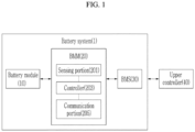
- FIG. 1 is a configuration diagram schematically showing a battery system 1, according to embodiments of the present disclosure.
- the battery system 1 may include a battery module 10 including one or more battery cells and capable of charging and discharging; a battery module manager (BMM) 20 that monitors a voltage, a current, a temperature, or the like of the battery module 10 and controls and manages it to prevent overcharge, overdischarge, or the like; and a battery management system (BMS) 30 that receives a signal from the BMM 20 and takes an appropriate action for the BMM based on the received signal.
- BMM battery module manager
- BMS battery management system
- the battery module 10 may include battery cells connected in series and/or in parallel.
- the battery module may supply electric power to external circuits outside of the battery system 1.
- the BMM 20 may be connected to the battery module 10 to monitor a state of the battery module 10.
- the BMM 20 may measure or calculate a voltage or a current of a gate, a source, a drain, or the like of a semiconductor switching element in order to monitor the voltage, the current, the temperature, or the like of the battery module 10.
- the voltage, the current, the temperature, or the like of the battery module 10 may be measured using a sensor provided adjacent to the semiconductor switching element.
- the BMM 20 may be an interface that receives measured values of various parameters described above, and may include a plurality of terminals, a circuit connected to the terminals to process received values, or the like.
- the BMM 20 may control on/off of a metal oxide semiconductor FET (MOSFET).
- MOSFET metal oxide semiconductor FET
- the BMM 20 may include a sensing portion (or a sensing unit) 201, a controller (a control portion or a control unit) 203, and a communication portion (or a communication unit) 205.
- the sensing portion 201 may obtain state data related to a state of the battery module 10 from the battery module 10.
- the sensing portion 201 may measure the voltage, the current, the temperature, or the like of the battery module 10.
- the controller 203 may receive the state data related to the battery module 10 from the sensing portion 201.
- the controller 203 may detect (or sense) an error occurring in the battery module 10 based on the state data.
- the controller 203 may control the communication portion 205 so that the communication portion 205 transmits a signal to the BMS 30 in response to a data signal received from the BMS 30. If an error occurs in communication between the controller 203 and the BMS 30 (for example, due to noise or the like), the controller 203 may detect the error, and may transmit a signal related to the error to the BMS 30.
- the controller 203 may change an operating state according to a signal received from the BMS 30.
- the controller 203 may include a micro controller unit (MCU).
- MCU micro controller unit
- the communication portion 205 may transmit and receive information or the signal related to the error to the BMS 30 under control of the controller 203.
- the communication portion 205 and the BMS 30 may communicate with each other through a low voltage (LV) wire.
- LV low voltage
- the BMM 20 may be connected to the BMS 30 so that operation of the BMM 20 is controlled based on a signal applied from the BMS 30.
- the BMS 30 may monitor a state of a battery pack including one or more battery modules 10 and the BMM 20.
- the BMS 30 may monitor a voltage, a current, a temperature, or the like of the battery pack.
- the BMS 30 may transmit a data signal to the BMM 20.
- the BMS 30 may monitor an operating state of the BMM 20 based on a signal received from the BMM 20.
- the battery system 1 may be connected to an external controller, also referred to herein as upper controller 40.
- An operation of the BMM 20 or the BMS 30 may be controlled based on a signal applied from the upper controller 40.
- the upper controller 40 may receive state data related to the state of the battery module 10 from the BMS 30, and may monitor the battery system 1.
- the BMS 30 and the upper controller 40 may communicate with each other through a controller area network (CAN) bus.
- the upper controller 40 may include an electronic control unit (ECU).
- FIG. 2 is a graph schematically illustrating signals transmitted and received by a battery module manager (BMM) and a battery management system (BMS) in normal operation of battery system 1, in accordance with embodiments of the disclosure.
- BMM battery module manager
- BMS battery management system
- the horizontal axis of the graph represents time, and various signals s1 - s6 are shown on the vertical axis.
- the BMS 30 may transmit data to the BMM 20.
- the BMS 30 may transmit a data signal s1 at an enable level H to the BMM 20.
- the BMM 20 may transmit a first state signal s2 at an enable level H to the BMS 30.
- the first state signal s2 at the enable level H may indicate a state in which the BMM 20 is communicating with the BMS 30.
- the first state signal s2 may be a signal related to data received from the BMS 30.
- the controller 203 may control the communication portion 205 to transmit the first state signal s2 at the enable level H to the BMS 30 as a response to the received data signal s1.
- the BMM 20 may transmit a second state signal s3 at a disable level L to the BMS 30.
- the second state signal s3 at the disable level L may indicate a state in which the communication between the BMM 20 and the BMS 30 is not interrupted. For example, if the first state signal s2 is transmitted at the enable level H during the time period t1 to t3, the controller 205 may control the communication portion 205 to transmit the second state signal s3 at the disable level L to the BMS 30.
- the BMM 20 may check a stop bit of data based on the received data signal s1.
- the stop bit may be a predetermined bit indicating that the data is the last data.
- the controller 203 may check the stop bit of the data based on the received data signal s1. If the stop bit is checked as positive (i.e. positively detected), the BMM 20 may transmit a third state signal s4 at an enable level H to the BMS 30 during the time period t2 to t4.
- the third state signal s4 at the enable level H may indicate data reception interruption. For example, if the stop bit is checked as positive, the controller 203 may control the communication portion 205 to transmit the third state signal s4 at the enable level H to the BMS 30 during the time period t2 to t4.
- the BMM 20 may transmit an interrupt flag s5 at a disable level L to the BMS 30.
- the interrupt flag s5 at the disable level L may indicate that no error has occurred in the state signals s2, s3, and s4.
- the controller 203 may control the communication portion 205 to transmit the interrupt flag s5 at the disable level L to the BMS 30.
- the BMS 30 may transmit a latch signal s6 at a disable level L to the BMM 20. If the interrupt flag s5 at the disable level L is transmitted, the above-described communication procedure may be followed. For example, during the time period t3 to t5, the BMM 20 may transmit the first state signal s2 at the disable level L to the BMS 30. During the time period t5 to t7, the BMS 30 may transmit the data signal s1 at the enable level H to the BMM 20, and the BMM 20 may transmit the first state signal s2 at the enable level H to the BMS 30. For example, if the BMM 20 checks (i.e. positively detects) a specific bit based on the received data signal s1, the BMM 20 may transmit the third state signal s4 at the enable level H to the BMS 30 during the time period t6 to t8.
- FIG. 3 is a graph schematically illustrating signals transmitted and received by the BMM and BMS in the case of a communication error occurring in the battery system 1 (that is, abnormal operation).
- the horizontal axis of the graph represents time, and various signals s1-s7 are shown on the vertical axis. Times t1 and t3 of FIG. 3 may correspond to the times t1 and t3 of FIG. 2 .
- a noise signal s7 may be applied to the BMM 20. Due to the noise signal s7, the BMM 20 may stop receiving the data signal s1 at a time t12 instead of the time t3. Therefore, a communication error may occur during the time period t12 to t3, in contrast to a case where the battery system 1 normally operates.
- the noise signal s7 may be applied to the BMM 20.
- the noise signal s7 may be applied to the LV wire so that an error may occur in operation of the communication portion 205 due to the noise signal s7.
- the BMS 30 may transmit the data signal s1 at the enable level H to the BMM 20 during times t1 to t12, and may transmit the data signal s1 at a disable level L to the BMM 20 during the time period t12 to t3.
- the BMM 20 may transmit the first state signal s2 at the enable level H to the BMS 30.
- the controller 203 may control the communication portion 205 to transmit the first state signal s2 at the enable level H to the BMS 30.
- the BMM 20 may transmit the second state signal s3 at the disable level L to the BMS 30.
- the controller 203 may control the communication portion 205 to transmit the second state signal s3 at the disable level L to the BMS 30 during the times t1 to 112 during which the first state signal s2 is transmitted.
- the BMM 20 may not check (i.e. may not positively detect, or detect a lack of, or detect a given value indicating a negative) the stop bit.
- the controller 203 may not check (i.e. not positively detect, or detect a lack of, or detect a given value indicating a negative) the stop bit.
- the BMM 20 may transmit the third state signal s4 at a disable level L to the BMS 30. For example, if the stop bit is not checked (i.e.
- the controller 203 may control the communication portion 205 to transmit the third state signal s4 at the disable level L to the BMS 30 during the time period t12 to t3.
- the BMM 20 may transmit the interrupt flag s5 at an enable level H to the BMS 30 at the time t3.
- the controller 203 may determine a level at which the third state signal s4 is transmitted. If the third state signal s4 at the disable level L is transmitted, the controller 203 may control the communication portion 205 to transmit the interrupt flag s5 at the enable level H to the BMS 30 at the time t3.
- the BMS 30 may transmit the latch signal s6 at an enable level H to the BMM 20. If the BMM 20 receives the latch signal s6 at the enable level H, it may operate in a latch mode.
- the latch mode may mean a mode in which the communication between the BMM 20 and the BMS 30 is interrupted (or stopped). For example, if the controller 203 checks the latch signal s6 at the enable level H, the controller 203 may change an operation mode of the BMM 20 to the latch mode. If the BMM 20 is in the latch mode, a series of communication procedures described with reference to FIG. 2 may be interrupted (or stopped). In some embodiments, although application of the noise signal s7 is stopped thereafter, communications of the battery system 1 may not proceed normally.
- FIG. 4 is a graph schematically illustrating signals transmitted and received by the BMM and BMS in a case where communication monitoring of the battery system of the embodiments is performed
- FIG. 5 is a flowchart schematically illustrating a portion of the communication monitoring method according to embodiments.
- the horizontal axis of the graph represents time, and various signals s1 - s8 are shown on the vertical axis. Times t1, t3, t5, t6, t7, and t8 of FIG. 4 may correspond to the times t1, t3, t5, t6, t7, and t8 of FIG. 2 .
- abnormal operation of the BMM 20 may occur due to the noise signal s7 described with reference to FIG. 3 .
- the noise signal s7 may be applied to the BMM 20.
- the BMS 30 may transmit the data signal s1 at the enable level H to the BMM 20 during the time period t1 to t12 due to the noise signal s7.
- the BMM 20 may transmit the first state signal s2 at the enable level H to the BMS 30, and may transmit the second state signal s3 at the disable level L to the BMS 30; during the time period 112 to t3, the BMM 20 may transmit the third state signal s4 at the disable level L.
- the BMM 20 may transmit the interrupt flag s5 at the enable level H to the BMS 30 (S501). If the BMS 30 receives the interrupt flag s5 at the enable level H, the BMS 30 may transmit the latch signal s6 at the enable level H to the BMM 20 (S503). The BMM 20 may operate in the latch mode according to the received latch signal at the enable level H (S505).
- the controller 203 may control the communication portion 205 to transmit the interrupt flag s5 at the enable level H to the BMS 30 at the time t3. If the BMS 30 receives the interrupt flag s5 at the enable level H, the BMS 30 may transmit the latch signal s6 at the enable level H to the BMM 20 at the time t31. If the controller 203 checks the latch signal s6 at the enable level H, it may change the operation mode to the latch mode. If the BMM 20 is in the latch mode, the series of communication procedures described with reference to FIG. 2 may be interrupted.
- the BMS 30 may determine whether a reference time has elapsed (S507). If it is determined that the reference time has elapsed, the BMS 30 may transmit a reset signal at an enable level H to the BMM 20 (S509), and the BMM 20 may reset the latch mode according to the received reset signal to operate normally (S511). If the BMS 30 determines that the reference time has not elapsed, it may then determine whether the reference time has elapsed.
- the reference time may be a predetermined time.
- the reference time may be set to 2 seconds.
- the present disclosure is not limited thereto, and the reference time may be a constant time or a variable time, and may be differently set according to a purpose and a situation in which the noise signal s7 is applied.
- the reset signal s8 may be a signal that controls the BMM 20 to release the latch mode and resume communication between the BMM 20 and the BMS 30.
- the BMS 30 may transmit the reset signal s8 at the enable level H to the BMM 20 during the time period t31 to t5.
- the controller 203 may reset the latch mode at the time t5 according to the received reset signal s8 to operate normally in a state in which communication between the controller 203 and the BMS 30 is possible. For example, unlike a case described above with reference to FIG. 4
- the latch mode of the BMM 20 may be maintained only during the time period t31 to t5 after the noise signal s7 is stopped, the data signal s1 may be normally received again, and the above-described series of communication procedures during the time period t5 to t8 may be followed.
- a communication abnormality phenomenon of the battery system may be efficiently monitored without additional cost, and an abnormal operation of the battery system may be reset at an optimal timing.
Landscapes
- Engineering & Computer Science (AREA)
- Physics & Mathematics (AREA)
- General Physics & Mathematics (AREA)
- Power Engineering (AREA)
- Manufacturing & Machinery (AREA)
- Chemical & Material Sciences (AREA)
- Chemical Kinetics & Catalysis (AREA)
- Electrochemistry (AREA)
- General Chemical & Material Sciences (AREA)
- Computer Networks & Wireless Communication (AREA)
- Signal Processing (AREA)
- Charge And Discharge Circuits For Batteries Or The Like (AREA)
Applications Claiming Priority (1)
| Application Number | Priority Date | Filing Date | Title |
|---|---|---|---|
| KR1020230049486A KR20240153146A (ko) | 2023-04-14 | 2023-04-14 | 배터리 시스템 및 배터리 시스템의 모니터링 방법 |
Publications (2)
| Publication Number | Publication Date |
|---|---|
| EP4447480A1 true EP4447480A1 (de) | 2024-10-16 |
| EP4447480B1 EP4447480B1 (de) | 2026-04-22 |
Family
ID=90364622
Family Applications (1)
| Application Number | Title | Priority Date | Filing Date |
|---|---|---|---|
| EP24162714.0A Active EP4447480B1 (de) | 2023-04-14 | 2024-03-11 | Batteriesystem und überwachungsverfahren des batteriesystems |
Country Status (4)
| Country | Link |
|---|---|
| US (1) | US20240348061A1 (de) |
| EP (1) | EP4447480B1 (de) |
| KR (1) | KR20240153146A (de) |
| CN (1) | CN118800982A (de) |
Families Citing this family (1)
| Publication number | Priority date | Publication date | Assignee | Title |
|---|---|---|---|---|
| EP4451500A1 (de) * | 2023-04-17 | 2024-10-23 | Valmet Automotive Oyj | Steuerung, system und verfahren |
Citations (2)
| Publication number | Priority date | Publication date | Assignee | Title |
|---|---|---|---|---|
| US20120013201A1 (en) * | 2010-07-14 | 2012-01-19 | Sinoelectric Powertrain Corporation | Battery pack fault communication and handling |
| US20200381926A1 (en) * | 2019-05-31 | 2020-12-03 | Texas Instruments Incorporated | Reset circuit for battery management system |
-
2023
- 2023-04-14 KR KR1020230049486A patent/KR20240153146A/ko active Pending
- 2023-10-27 US US18/384,718 patent/US20240348061A1/en active Pending
-
2024
- 2024-02-20 CN CN202410187942.9A patent/CN118800982A/zh active Pending
- 2024-03-11 EP EP24162714.0A patent/EP4447480B1/de active Active
Patent Citations (2)
| Publication number | Priority date | Publication date | Assignee | Title |
|---|---|---|---|---|
| US20120013201A1 (en) * | 2010-07-14 | 2012-01-19 | Sinoelectric Powertrain Corporation | Battery pack fault communication and handling |
| US20200381926A1 (en) * | 2019-05-31 | 2020-12-03 | Texas Instruments Incorporated | Reset circuit for battery management system |
Also Published As
| Publication number | Publication date |
|---|---|
| CN118800982A (zh) | 2024-10-18 |
| EP4447480B1 (de) | 2026-04-22 |
| US20240348061A1 (en) | 2024-10-17 |
| KR20240153146A (ko) | 2024-10-22 |
Similar Documents
| Publication | Publication Date | Title |
|---|---|---|
| KR102568627B1 (ko) | 슬레이브 bms 점검 시스템 및 방법 | |
| EP3958006B1 (de) | Batteriediagnosevorrichtung und -verfahren | |
| KR102390394B1 (ko) | 메인 배터리와 서브 배터리를 제어하기 위한 장치 및 방법 | |
| US8736229B2 (en) | Battery control circuit for reducing power consumption | |
| US20220329086A1 (en) | System and method for managing battery | |
| KR102785104B1 (ko) | 병렬 배터리 릴레이 진단 장치 및 방법 | |
| CN106537718A (zh) | 电池管理 | |
| US11418042B2 (en) | Battery management unit | |
| EP4156374A1 (de) | Batteriepack, master-bms und slave-bms zur diagnose der ursache eines kommunikationsfehlers | |
| EP3671236B1 (de) | Vorrichtung und verfahren zur laufzeitüberwachungsdiagnose | |
| JP2006149068A (ja) | 組電池管理装置 | |
| KR102734327B1 (ko) | 차량용 배터리 시스템 및 그 제어방법 | |
| US20140152267A1 (en) | Battery systems and remaining capacity management systems for secondary battery | |
| EP4447480B1 (de) | Batteriesystem und überwachungsverfahren des batteriesystems | |
| EP4016099B1 (de) | Batteriediagnosevorrichtung und -verfahren | |
| KR20200088153A (ko) | 전류 센서 진단 장치 및 이를 포함하는 배터리 팩 | |
| KR101439233B1 (ko) | 보조 전원을 구비한 배터리 관리 시스템 | |
| US7745039B2 (en) | System and method for controlling a rechargeable battery | |
| KR20240022930A (ko) | 배터리 셀 진단 장치 및 그것의 동작 방법 | |
| KR20230174322A (ko) | 내부 누설 전류를 차단하기 위한 기능을 제공하는 배터리 셀 컨트롤러 |
Legal Events
| Date | Code | Title | Description |
|---|---|---|---|
| PUAI | Public reference made under article 153(3) epc to a published international application that has entered the european phase |
Free format text: ORIGINAL CODE: 0009012 |
|
| STAA | Information on the status of an ep patent application or granted ep patent |
Free format text: STATUS: REQUEST FOR EXAMINATION WAS MADE |
|
| 17P | Request for examination filed |
Effective date: 20240311 |
|
| AK | Designated contracting states |
Kind code of ref document: A1 Designated state(s): AL AT BE BG CH CY CZ DE DK EE ES FI FR GB GR HR HU IE IS IT LI LT LU LV MC ME MK MT NL NO PL PT RO RS SE SI SK SM TR |
|
| GRAP | Despatch of communication of intention to grant a patent |
Free format text: ORIGINAL CODE: EPIDOSNIGR1 |
|
| STAA | Information on the status of an ep patent application or granted ep patent |
Free format text: STATUS: GRANT OF PATENT IS INTENDED |
|
| INTG | Intention to grant announced |
Effective date: 20251216 |
|
| GRAS | Grant fee paid |
Free format text: ORIGINAL CODE: EPIDOSNIGR3 |
|
| GRAA | (expected) grant |
Free format text: ORIGINAL CODE: 0009210 |
|
| STAA | Information on the status of an ep patent application or granted ep patent |
Free format text: STATUS: THE PATENT HAS BEEN GRANTED |
|
| AK | Designated contracting states |
Kind code of ref document: B1 Designated state(s): AL AT BE BG CH CY CZ DE DK EE ES FI FR GB GR HR HU IE IS IT LI LT LU LV MC ME MK MT NL NO PL PT RO RS SE SI SK SM TR |
|
| REG | Reference to a national code |
Ref country code: CH Ref legal event code: F10 Free format text: ST27 STATUS EVENT CODE: U-0-0-F10-F00 (AS PROVIDED BY THE NATIONAL OFFICE) Effective date: 20260422 Ref country code: GB Ref legal event code: FG4D |