EP4447471A1 - Robust optical monitoring device and operating method thereof - Google Patents
Robust optical monitoring device and operating method thereof Download PDFInfo
- Publication number
- EP4447471A1 EP4447471A1 EP24170102.8A EP24170102A EP4447471A1 EP 4447471 A1 EP4447471 A1 EP 4447471A1 EP 24170102 A EP24170102 A EP 24170102A EP 4447471 A1 EP4447471 A1 EP 4447471A1
- Authority
- EP
- European Patent Office
- Prior art keywords
- monitoring device
- optical monitoring
- compartment
- camera
- hvac
- Prior art date
- Legal status (The legal status is an assumption and is not a legal conclusion. Google has not performed a legal analysis and makes no representation as to the accuracy of the status listed.)
- Pending
Links
Images






Classifications
-
- H—ELECTRICITY
- H04—ELECTRIC COMMUNICATION TECHNIQUE
- H04N—PICTORIAL COMMUNICATION, e.g. TELEVISION
- H04N23/00—Cameras or camera modules comprising electronic image sensors; Control thereof
- H04N23/50—Constructional details
- H04N23/52—Elements optimising image sensor operation, e.g. for electromagnetic interference [EMI] protection or temperature control by heat transfer or cooling elements
-
- H—ELECTRICITY
- H04—ELECTRIC COMMUNICATION TECHNIQUE
- H04N—PICTORIAL COMMUNICATION, e.g. TELEVISION
- H04N23/00—Cameras or camera modules comprising electronic image sensors; Control thereof
- H04N23/60—Control of cameras or camera modules
- H04N23/66—Remote control of cameras or camera parts, e.g. by remote control devices
- H04N23/661—Transmitting camera control signals through networks, e.g. control via the Internet
- H04N23/662—Transmitting camera control signals through networks, e.g. control via the Internet by using camera arrangements where one camera controls another camera to affect the control of camera image capture, e.g. placing the camera in a desirable condition to capture a desired image
-
- G—PHYSICS
- G01—MEASURING; TESTING
- G01N—INVESTIGATING OR ANALYSING MATERIALS BY DETERMINING THEIR CHEMICAL OR PHYSICAL PROPERTIES
- G01N21/00—Investigating or analysing materials by the use of optical means, i.e. using sub-millimetre waves, infrared, visible or ultraviolet light
- G01N21/75—Systems in which material is subjected to a chemical reaction, the progress or the result of the reaction being investigated
- G01N21/77—Systems in which material is subjected to a chemical reaction, the progress or the result of the reaction being investigated by observing the effect on a chemical indicator
- G01N21/78—Systems in which material is subjected to a chemical reaction, the progress or the result of the reaction being investigated by observing the effect on a chemical indicator producing a change of colour
- G01N21/81—Indicating humidity
-
- F—MECHANICAL ENGINEERING; LIGHTING; HEATING; WEAPONS; BLASTING
- F24—HEATING; RANGES; VENTILATING
- F24F—AIR-CONDITIONING; AIR-HUMIDIFICATION; VENTILATION; USE OF AIR CURRENTS FOR SCREENING
- F24F11/00—Control or safety arrangements
- F24F11/30—Control or safety arrangements for purposes related to the operation of the system, e.g. for safety or monitoring
-
- F—MECHANICAL ENGINEERING; LIGHTING; HEATING; WEAPONS; BLASTING
- F24—HEATING; RANGES; VENTILATING
- F24F—AIR-CONDITIONING; AIR-HUMIDIFICATION; VENTILATION; USE OF AIR CURRENTS FOR SCREENING
- F24F11/00—Control or safety arrangements
- F24F11/50—Control or safety arrangements characterised by user interfaces or communication
- F24F11/52—Indication arrangements, e.g. displays
-
- F—MECHANICAL ENGINEERING; LIGHTING; HEATING; WEAPONS; BLASTING
- F24—HEATING; RANGES; VENTILATING
- F24F—AIR-CONDITIONING; AIR-HUMIDIFICATION; VENTILATION; USE OF AIR CURRENTS FOR SCREENING
- F24F11/00—Control or safety arrangements
- F24F11/62—Control or safety arrangements characterised by the type of control or by internal processing, e.g. using fuzzy logic, adaptive control or estimation of values
- F24F11/63—Electronic processing
- F24F11/64—Electronic processing using pre-stored data
-
- F—MECHANICAL ENGINEERING; LIGHTING; HEATING; WEAPONS; BLASTING
- F24—HEATING; RANGES; VENTILATING
- F24F—AIR-CONDITIONING; AIR-HUMIDIFICATION; VENTILATION; USE OF AIR CURRENTS FOR SCREENING
- F24F11/00—Control or safety arrangements
- F24F11/88—Electrical aspects, e.g. circuits
-
- F—MECHANICAL ENGINEERING; LIGHTING; HEATING; WEAPONS; BLASTING
- F24—HEATING; RANGES; VENTILATING
- F24F—AIR-CONDITIONING; AIR-HUMIDIFICATION; VENTILATION; USE OF AIR CURRENTS FOR SCREENING
- F24F11/00—Control or safety arrangements
- F24F11/89—Arrangement or mounting of control or safety devices
-
- F—MECHANICAL ENGINEERING; LIGHTING; HEATING; WEAPONS; BLASTING
- F24—HEATING; RANGES; VENTILATING
- F24F—AIR-CONDITIONING; AIR-HUMIDIFICATION; VENTILATION; USE OF AIR CURRENTS FOR SCREENING
- F24F13/00—Details common to, or for air-conditioning, air-humidification, ventilation or use of air currents for screening
- F24F13/20—Casings or covers
-
- G—PHYSICS
- G01—MEASURING; TESTING
- G01K—MEASURING TEMPERATURE; MEASURING QUANTITY OF HEAT; THERMALLY-SENSITIVE ELEMENTS NOT OTHERWISE PROVIDED FOR
- G01K1/00—Details of thermometers not specially adapted for particular types of thermometer
- G01K1/02—Means for indicating or recording specially adapted for thermometers
- G01K1/024—Means for indicating or recording specially adapted for thermometers for remote indication
-
- G—PHYSICS
- G01—MEASURING; TESTING
- G01K—MEASURING TEMPERATURE; MEASURING QUANTITY OF HEAT; THERMALLY-SENSITIVE ELEMENTS NOT OTHERWISE PROVIDED FOR
- G01K1/00—Details of thermometers not specially adapted for particular types of thermometer
- G01K1/14—Supports; Fastening devices; Arrangements for mounting thermometers in particular locations
-
- G—PHYSICS
- G01—MEASURING; TESTING
- G01N—INVESTIGATING OR ANALYSING MATERIALS BY DETERMINING THEIR CHEMICAL OR PHYSICAL PROPERTIES
- G01N21/00—Investigating or analysing materials by the use of optical means, i.e. using sub-millimetre waves, infrared, visible or ultraviolet light
- G01N21/01—Arrangements or apparatus for facilitating the optical investigation
-
- G—PHYSICS
- G05—CONTROLLING; REGULATING
- G05B—CONTROL OR REGULATING SYSTEMS IN GENERAL; FUNCTIONAL ELEMENTS OF SUCH SYSTEMS; MONITORING OR TESTING ARRANGEMENTS FOR SUCH SYSTEMS OR ELEMENTS
- G05B19/00—Program-control systems
- G05B19/02—Program-control systems electric
- G05B19/04—Program control other than numerical control, i.e. in sequence controllers or logic controllers
-
- H—ELECTRICITY
- H04—ELECTRIC COMMUNICATION TECHNIQUE
- H04N—PICTORIAL COMMUNICATION, e.g. TELEVISION
- H04N23/00—Cameras or camera modules comprising electronic image sensors; Control thereof
- H04N23/56—Cameras or camera modules comprising electronic image sensors; Control thereof provided with illuminating means
-
- H—ELECTRICITY
- H04—ELECTRIC COMMUNICATION TECHNIQUE
- H04N—PICTORIAL COMMUNICATION, e.g. TELEVISION
- H04N7/00—Television systems
- H04N7/18—Closed-circuit television [CCTV] systems, i.e. systems in which the video signal is not broadcast
- H04N7/183—Closed-circuit television [CCTV] systems, i.e. systems in which the video signal is not broadcast for receiving images from a single remote source
-
- F—MECHANICAL ENGINEERING; LIGHTING; HEATING; WEAPONS; BLASTING
- F24—HEATING; RANGES; VENTILATING
- F24F—AIR-CONDITIONING; AIR-HUMIDIFICATION; VENTILATION; USE OF AIR CURRENTS FOR SCREENING
- F24F2110/00—Control inputs relating to air properties
- F24F2110/10—Temperature
-
- G—PHYSICS
- G01—MEASURING; TESTING
- G01K—MEASURING TEMPERATURE; MEASURING QUANTITY OF HEAT; THERMALLY-SENSITIVE ELEMENTS NOT OTHERWISE PROVIDED FOR
- G01K2201/00—Application of thermometers in air-conditioning systems
Definitions
- the disclosure generally relates to an optical monitoring device and more particularly relates to a robust optical monitoring device capable of reducing the impact of high temperature on its performance and a method of operating the same in a Heating Ventilation Air Conditioning and Refrigeration (HVAC/R) system.
- HVAC/R Heating Ventilation Air Conditioning and Refrigeration
- HVAC/R systems are used with refrigerants that are either near or below atmospheric pressure. Such refrigerants tend to absorb moisture and inhibit chiller performance. Therefore, HVAC/R systems are required to be monitored for moisture level in the refrigerant. For this purpose, HVAC/R systems are employed with sight glass with a color-changing material exposed to the refrigerant stream, with the color indicating a moisture level of the refrigerant.
- Said monitoring device essentially comprises a camera to capture images of the sight glass, an illumination mechanism, and a wireless connection circuit to communicate the sight glass images captured by the camera wirelessly. Based on these images, conditions such as moisture content exceeding prescribed levels, insufficient refrigerant charge, or presence of non-condensable gases are detected, and necessary actions are performed.
- heat generated from the power supply of the optical monitoring device causes high temperatures which not only reduce the performance of the camera, but also hamper the wireless connection.
- heat may be generated when an AC power input to the monitoring device is converted into DC.
- continuous wireless operation may raise the ambient temperature by over 20-30 degrees Celsius.
- Such high temperatures may exceed a predefined maximum system temperature suitable for electronic circuits and particularly for the wireless connectivity circuits. This may result in a weak, intermittent, or no wireless connection.
- no measures have been suggested previously to improve the illumination quality of the sight glass or deal with fog accumulation on its surface.
- the present invention provides an optical monitoring device comprising: a housing comprising a first compartment and a second compartment, the first compartment comprising a camera circuit board and a wireless connection circuit board, wherein the second compartment comprises a supply circuit board, and wherein the housing further comprises: an isolation cell to isolate the first compartment and the second compartment, a camera configured to be disposed in the first compartment of the housing to receive images associated with a sight glass, and an illumination board disposed within the first compartment of the housing positioned to project light for operation of the camera.
- the isolation cell may comprise at least one cable to connect the camera circuit board and the illumination board with the supply circuit board.
- the housing may be configured to be mounted on a Heating, Ventilation, Air Conditioning and Refrigeration (HVAC/R) system, the HVAC/R system comprising the sight glass within a piping network.
- HVAC/R Heating, Ventilation, Air Conditioning and Refrigeration
- the optical monitoring device may further comprise a moisture absorber in the isolation cell, wherein the moisture absorber comprises one of a hydrogel and silica gel.
- the optical monitoring device may further comprise a light dispersion layer placed between the illumination board and the sight glass of the HVAC/R system.
- the optical monitoring device may comprise a light dispersion layer placed between the illumination board and a window in the optical monitoring device.
- the camera may be placed at a predefined distance from the sight glass of an HVAC/R system.
- the optical monitoring device may further comprise a guiding mechanism to guide heat generated from the supply circuit board of the second compartment towards the sight glass.
- the invention provides a Heating, Ventilation, Air Conditioning and Refrigeration (HVAC/R) system comprising the optical monitoring device according to the first aspect, optionally including any other features as described above, wherein the HVAC/R system further comprises the sight glass, the sight glass including an anti-fog film.
- HVAC/R Heating, Ventilation, Air Conditioning and Refrigeration
- the invention provides a method of operating an optical monitoring device mounted on a Heating, Ventilation, Air Conditioning and Refrigeration (HVAC/R) system, the method comprising: measuring a temperature inside the optical monitoring device; determining whether the measured temperature is less than a predefined threshold temperature; in response to determining that the measured temperature is less than the predefined threshold temperature, establishing, by the optical monitoring device, a wireless connection to transmit at least one image, to be captured by a camera; in response to receipt of a trigger, capturing, by the camera, the at least one image of a sight glass of the HVAC/R system; and transmitting the at least one image over the wireless connection.
- HVAC/R Heating, Ventilation, Air Conditioning and Refrigeration
- HVAC/R Heating, Ventilation, Air Conditioning and Refrigeration
- the trigger comprises one of a manual trigger received via an application or an automated trigger received from a controller.
- the method comprises reporting an abnormal operating status of the optical monitoring device to the controller or a remote application hosted on a user device.
- the optical monitoring device is the optical monitoring device according to the first aspect, optionally including any other optional features of the optical monitoring device as described above.
- Figure 1A illustrates a general cross-sectional view of an optical monitoring device 100.
- the optical monitoring device 100 may include a housing 102.
- the housing 102 may include a first compartment 104 and a second compartment 106.
- the housing 102 may be made of a metal (e.g., aluminium, iron, alloys thereof, and the like), a plastic (e.g., polyethylene, polyethylene terephthalate (PET), polyvinylchloride (PVC), polyoxymethylene (POM), polycarbonate, polytetrafluoroethylene (PTFE), acrylonitrile butadiene styrene (ABS), and the like), or a combination including at least one of the foregoing.
- one or more metal parts of the housing 102 may be treated as heat transfer elements or radiators.
- the first compartment 104 may include a camera circuit board, a wireless connection circuit board, and an illumination board arranged to illuminate and view a window 110 formed by an opening/aperture at an outer periphery of one of the walls of the housing 102.
- an optically transmissive material such as, but not limited to, glass, clear plastic sheet, or the like, may be placed in the window 110 to prevent the entry of debris, moisture, insect, or the like into the housing 102 while still permitting the view through the window 110.
- the second compartment 106 may include a supply circuit board arranged to provide power to components of the optical monitoring device 100, such as a camera circuit board, an illumination board, and the like.
- the first compartment 104 and the second compartment 106 may be separated from each other by an isolation cell 108.
- the isolation cell 108 as described in detail in the following paragraphs with respect to figure 4 , may be arranged to thermally isolate the first compartment 104 and the second compartment 106, and guide cables between the circuit boards of both the compartments.
- the optical monitoring device 100 may be installed on a pipe of the piping system of an HVAC/R system 112 to monitor the condition of a color changing material and the fluid flowing through a sight glass 114, as shown in figure 1B .
- Figure 2 illustrates a detailed view of the first compartment 104 of the optical monitoring device 100.
- the first compartment 104 may include a camera circuit board 202 which may house a camera 204, a processing unit 205, and a wireless connection circuit board 206.
- the camera 204 may include any suitable digital camera capable of capturing images.
- the camera 204 captures photos of the sight glass 114 placed on the HVAC/R system 112.
- the camera 204 may be any board-level camera, e.g., mounted in electrical communication with, and directly onto, the camera circuit board 202.
- the processing unit 205 may be in communication with the camera 204 and the wireless connection circuit board 206.
- the processing unit 205 may include firmware to identify color of sight glass 114.
- Said firmware may be a set of instructions executable by the processing unit 205 to recognise the color of sight glass 114 from the images taken by the camera 204 and sets its registers with binary information about dry/wet or abnormal color of sight glass 114.
- the process of capturing images from the camera 204 and recognising the color of the sight glass 114 to get one or more sets of binary information may be repeated for n number of times. An average of the one or more binary set may be computed and the resulting average binary information may be logged in the registers of the processing unit 205.
- the processing unit 205 may be a controller or a processor.
- the processing unit 205 may include a central processing unit (CPU) or similar controller (e.g., programmable gate array (FPGA), application specific integrated circuit (ASIC)) for processing image data output from the camera 204.
- the processing unit 205 may exchange the binary information between the optical monitoring device 100 and a controller 116 of the HVAC/R system 112. In an embodiment, the information may be exchanged with the controller 116 using a Modbus cable.
- the HVAC/R controller 116 may pull that information from the optical monitoring device 100 and may process it to take relevant actions.
- the HVAC/R controller 116 may provide the information from the optical monitoring device 100 for a first threshold period of time. For example, in case abnormal color of the sight glass 114 is detected, such information may be provided by displaying either on a display monitor of the optical monitoring device 100 or on the user interface of an application installed on the user equipment. In another embodiment, the controller 116 may issue an alarm after the first threshold period of time is expired and wait for a second threshold period of time for the system 112 to be repaired. In yet another embodiment, if the second threshold period of time is also expired and the system 112 has not been repaired, the controller 116 may automatically switch off the HVAC/R system 112.
- the wireless connection circuit board 206 may be in communication with the camera 204 and the processing unit 205.
- the wireless connection circuit board 206 may be adapted to transmit image data captured from the camera 204 to an external device for example, via a wireless network such as Bluetooth, Bluetooth low energy, Wi-Fi, ZigBee, Z-wave, or the like.
- the external device may include user device, such as, but not limited to, a mobile phone, tablet, or portable computer.
- the wireless connection circuit board 206 may be used to support wireless connection to send images of the sight glass 114 to a web server on an operator's demand.
- the web server and its contents may be accessible by the external devices, via an application installed thereon.
- the camera circuit board 202 may be positioned at a distance from the sight glass 114 that is sufficient to provide optimum optical focal length within the optical monitoring device 100.
- the camera circuit board 202 may be mounted in handles fixed in the enclosure of the first compartment 104 at about 10 cm from the position of the window 110. Consequently, the impact, on the camera 204, of the temperature in the sight glass of the HVAC/R system or the pipe of the piping system of the HVAC/R system 112 passing through the sight glass 114 may be reduced by the distance maintained between camera circuit board 202 and the sight glass 114 visible through the window 110 of the optical monitoring device 100.
- the distance of the camera circuit board 202 may be maintained from the window 110 of the optical monitoring device 100 since the distance relation between the window 110 and the sight glass 114 is constant.
- the distance between the camera circuit board 202 and the window 110 may make room for the implementation of an illumination board which may project light at the window 110 and illuminate the view of the camera 204 installed on the camera circuit board 202.
- An illumination board 208 may be installed between the camera circuit board 202 and the window 110 of the optical monitoring device 100.
- the illumination board 208 may include one or more light sources 212 disposed in operable communication with the power supply (supply board 302, located in the second compartment 106 of the optical monitoring device 100), and an aperture 214.
- the aperture 214 may be provided in a line-of-sight through the illumination board 208.
- the aperture 214 may allow the lens of the camera 204 to view the window 110 through the illumination board 208.
- the illumination of the one or more light sources 212 may be controlled, for example, by allowing power to flow from the power supply to the one or more light sources 212 when the camera 204 is used to capture images of the sight glass 114.
- the one or more light sources 212 may include any suitable light source, such as but not limited to, light emitting diodes (LED), organic LEDs, polymer LEDs, and other electroluminescence sources.
- a light dispersion layer 210 may be placed between the illumination board 208 and the sight glass 114 of the HVAC/R system 112. In an embodiment, the light dispersion layer 210 may be arranged to uniformly spread the light coming from the light sources of the illumination board 208. The light dispersion layer 210 may be placed in a non-intrusive manner such that field of view of the camera 204 is not obscured. In an embodiment, the light dispersion layer 210 may be placed within a predefined threshold distance from the illumination board 208. In an exemplary embodiment, the light dispersion layer 210 may be at a 5mm distance from the illumination board 208. In an exemplary embodiment, the distance of the light dispersion layer 210 from the illumination board 208 may not be more than 10mm.
- the light dispersion layer 210 may be integrated with the light sources on the illumination board 208.
- the dispersion layer 210 may be placed as a paint or separately, for example, as a rectangular layer with an aperture 216 to allow the camera 204 to operate.
- the light dispersion layer 210 may provide thermal isolation to the components contained within the first compartment of the optical monitoring device 100.
- the light dispersion layer 210 may be made of a heat-resistant material such as, but not limited to, polycarbonate, acrylic or PMMA - Poly (methyl methacrylate).
- the light dispersion layer 210 may impact the heat flow and acts as a separate layer which may partially isolate upper part of first compartment with the circuit boards from the sight glass 114 and the pipe of the HVAC/R system 112.
- the light dispersion layer 210 may include another aperture 216 aligned with the aperture 212 of the illumination board 208 to enable the camera 204 to view the window 110 of the optical monitoring device 100 therethrough.
- the light dispersion layer 210 may be a sheet made of materials including, but not limited to, polycarbonate, acrylic or PMMA - Poly (methyl methacrylate).
- a final aperture 218 looking over the window 110 may be provided at the bottom of the first compartment 104.
- the final aperture 218 may be aligned with the lens of the camera 204, the aperture 214 of the illumination board 208, and the aperture 216 of the light dispersion layer 210.
- the apertures 214, 216, and 218 may provide a clear line of sight to the camera 204 for viewing the sight glass 114 through the window 110.
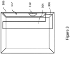
- Figure 3 illustrates a detailed view of the second compartment 106 of the optical monitoring device 100.
- the second compartment 106 may include a supply circuit board 302 to provide power supply to the components of the optical monitoring device 100.
- the supply circuit board 302 may be aligned to the vertical wall adjacent to the adjacent cell, i.e., the isolation cell 108.
- the supply circuit board 302 may include any suitable source for power supply, for example, but not limited to, a local power grid, site power supply, or a self-contained power storage device.
- the supply circuit board 302 may be connected with the controller 116 of the HVAC/R system 112 and draws power directly from the controller 116.
- the supply circuit board 302 is the component of the optical monitoring device 100 which generates heat while converting AC power input into DC power output and causes the ambient temperature to rise within the optical monitoring device 100. Encapsulating the supply circuit board 302 in a separate enclosure (i.e., the second compartment 106) may thermally isolate and thereby prevent other components of the optical monitoring device 100 from the impact of high temperature caused by the supply circuit board 302.
- the heat generated by the supply circuit board 302 may prevent the accumulation of moisture on the components of the second compartment 106 since the dew point of the compartment gets elevated from the high ambient temperature, thereby avoiding condensation. Therefore, any possibility of a short circuit in the power components of the supply board circuit 302 is reduced.
- the heat generated in the second compartment may be used to dry the sight glass and eliminate moisture therefrom.
- the second compartment 106 may include a guiding mechanism 304 to guide the heat flow from the second compartment towards the window 110 of the optical monitoring device 100 and direct it onto the sight glass of the HVAC/R system.
- the guiding mechanism 304 may include a covering made of heat-resistant material. The covering may have an opening 306 near the bottom of the second compartment 106. The heat generated in the second compartment 106 may be channelled through the guiding mechanism 204 and exhausted towards the window 110 through the opening 306.
- a memory storage device 310 may be provided in the second compartment 106.
- the memory storage device 310 may store one or more instant images output from the camera 204.
- the memory storage device 310 may be connected with the camera 204 and the processing unit 205 in the first compartment 104.
- the memory storage device 310 may be integrated with the processing unit 205.
- the memory storage device 310 may act as a temporary buffer or cache to hold the images captured by the camera 204.
- the processing unit 205 may process the images temporarily held in the memory storage device 310 to set its register with binary information on the operating status of the sight glass 114.
- the memory storage device 310 may also be placed in the first compartment 104 on the camera circuit board 202.
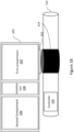
- Figure 4 illustrates a detailed view of the isolation cell 108 of the optical monitoring device 100.
- the isolation cell 108 may be placed between the first compartment 104 and the second compartment 106 of the optical monitoring device 100. All the cables 402 leading from the supply circuit board 302 to the camera circuit board 202 and the illumination board 208 may be contained in the isolation cell 108. The isolation cell 108 may also contain cables, if any, connecting the camera circuit board 202 and the illumination board 208.
- the isolation cell 108 may thermally isolate the first compartment 104 from the effects of high temperature and heat generated by the supply circuit board 302 in the second compartment 106.
- the isolation cell 108 may be a moulded enclosure consisting of two additional partitions or walls 406a and 406b and may be made of any heat-resistant material such as, but not limited to, plastic, ceramic, or a combination thereof. Said walls 406a and 406b may be isolators and may make the isolation cell 108 narrow. In an embodiment, the walls 406a and 406b may allow mechanical placement of a moisture absorber 404 and the cables 402. Additionally, the walls 406 a and 406b may also provide support for circuit boards in adjacent compartments.
- the moisture absorber 404 may be fixed mechanically in the isolation cell 108 at one position.
- the moisture absorber 404 may include any material capable of absorbing moisture from its surrounding environment, such as, but not limited to, hydrogel, silica gel, or the like.
- the moisture absorber 404 may prevent the accumulation of moisture on the internal components of the optical monitoring device 100. This may reduce the impact of moisture that may be present during installation in a piping system of the HVAC/R system 112.
- Figure 5 illustrates a cross-sectional view of an optical monitoring device installed onto a sight glass in a heating, ventilation, and air conditioning and refrigeration (HVAC/R) system.
- HVAC/R heating, ventilation, and air conditioning and refrigeration
- the window 110 through the optical monitoring device 100 may be configured to align with the aperture of the illumination board 208, the aperture of the light dispersion layer 210, and the lens of the camera 204 installed on the camera circuit board 202 such that the camera 204 may clearly view the sight glass 114 of the HVAC/R system 112 through the window 110 of the optical monitoring device 100.
- the saturation temperature of the air within the housing of the sight glass 114 is greater than the temperature of the transparent surface of the sight glass 114, water condensation may occur on the surface of the sight glass 114. Condensation on the transparent surface of the sight glass 114 may cause an accumulation of moisture or water which might obscure the view of the camera 204.
- an anti-fog film or coating may be placed on the sight glass 114 to mitigate the occurrence of condensation on it blocking the view of the camera 204 through it.
- the optical monitoring device 100 may be installed on the sight glass 114 with an anti-fog film or coating applied to it.
- the isolation cell 108 may also be used to lead cables for connecting illumination board 208 and the camera circuit board 202 within the first compartment 104.
- the optical monitoring device 100 may be installed over a piping section of the HVAC/R system 112, as illustrated in figure 5 , in a gauge having a sight glass 114 for allowing visual display of the color change material sample to be viewed through the optical monitoring device 100.
- FIG. 6 illustrates a flowchart depicting a method 600 of operating an optical monitoring device mounted on a Heating, Ventilation, Air Conditioning and refrigeration (HVAC/R) system.
- HVAC/R Heating, Ventilation, Air Conditioning and refrigeration
- the method 600 of operating the optical monitoring device 100 mounted on the HVAC/R system 112 is disclosed.
- the method 600 may include, measuring a temperature inside first compartment of the optical monitoring device 100.
- the temperature may be measured in the vicinity of camera 204 disposed on the camera circuit board 202.
- the temperature may be measured by temperature sensing element like thermistor
- the method 600 may include determining whether the temperature is less than a predefined threshold temperature.
- the predefined threshold temperature may be a maximum ambient temperature that may be allowed for the functioning of the internal components of the optical monitoring device 100, such as the camera 204 and the wireless connection circuit board 206 as they may be severely affected if the temperature rises above the predefined threshold temperature.
- the predefined threshold temperature may be set at 65 degrees Celsius. In another exemplary embodiment, the predefined threshold temperature may be set at 70 degrees Celsius. Since the continuous working of a wireless connection may considerably raise the ambient temperature, it ultimately hampers the wireless connection. Establishing the wireless connection only when the temperature is below the predefined threshold temperature may help in mitigating the issue of rising temperature.
- the method 600 for operating an optical monitoring device may include, at step 606, establishing a wireless connection to transmit at least one image, to be captured by a camera 204, in response to determining the temperature being less than a threshold temperature.
- the wireless connection may be established with an application installed in a user equipment, UE.
- the UE may be a smartphone, laptop, or desktop having a user interface capable of displaying the optical monitoring device 100 information.
- the user interface may also be capable of sending a trigger to the optical monitoring device 100, to capture images of the sight glass 114 and share the same over a wireless connection.
- the terms ⁇ user equipment' and ⁇ user device' have been used interchangeably throughout the specification.
- the method 600 may include, in response to receipt of a trigger, the camera 204 may capture the images of the sight glass 114 as viewed through the window 110.
- the trigger may be a manual trigger received from an application installed on the external device used by the operator or an automated trigger received from the controller 116 of the HVAC/R system 112.
- the illumination of the window of the optical monitoring device may also be controlled.
- the one or more light sources 212 may be powered on after detecting that the camera 204 is being used to capture image data. Consequently, the illumination timing of the window 110 may also be managed to correlate with the image capturing timing of the camera 204. Accordingly, images of the sight glass 114 may be captured through the illuminated window 110 of the optical monitoring device 100.
- the method 600 may include, at step 610, transmitting at least one image over the wireless connection to the web server accessible by a user equipment being used by the operator of the HVAC/R system 112.
- FIG. 7 illustrates a flowchart depicting the workflow 700 of the method 600 of operating an optical monitoring device 100 mounted on the Heating, Ventilation, Air Conditioning and refrigeration (HVAC/R) system.
- Block 701 depicts the method step of temperature measurement inside the optical monitoring device 100
- block 702 depicts determining if the measured temperature is over the predefined threshold temperature. If the measured temperature is over the threshold temperature, the controller 116 is informed by the optical monitoring device at block 703 indicating abnormal operating status of said optical monitoring device. In an embodiment, the abnormal operating status of the optical monitoring device may also be informed to an application hosted on a user device. However, if the temperature is below the threshold temperature, a wireless connection with the external user equipment may be established at block 704.
- HVAC/R Heating, Ventilation, Air Conditioning and refrigeration
- the optical monitoring device 100 then waits to receive a trigger to capture images of the sight glass 114 as shown in block 705.
- the trigger may be a manual trigger received via the application installed on the external device used by the operator or an automated trigger received from the controller 116 of the HVAC/R system 112. Once a trigger is received, at least one image of the sight glass 114 is captured at block 706 and transmitted to the user equipment at block 707.
- FIG. 8 illustrates a flowchart depicting an alternate workflow 800 of the method 600 for operating the optical monitoring device mounted on the HVAC/R system 112.
- the workflow 800 may be followed when the optical monitoring device 100 is operated using an application installed on the user equipment.
- a trigger to capture images of the sight glass 114 may be received from the application, at block 801.
- the system may wait for N minutes for the wireless connection to be established, and again check if the wireless connection has come up at block 805. If the wireless connection is still not established, an error is reported on the user interface of the application, at block 806. However, if the wireless connection comes up, the temperature is measured at block 807.
- the temperature is measured at block 807. If the measured temperature is over the predefined threshold temperature, at block 808, the system may wait and measure the temperature again until the temperature falls under the threshold temperature, at block 808. When the temperature is found to be below the threshold temperature, the optical monitoring device 100 may capture images of the sight glass 114 at block 809 and transmit the captured images at block 810.
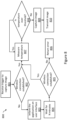
- Figure 9 illustrates a flowchart depicting yet another workflow 900 of the method 600 for operating the optical monitoring device 100 mounted on the HVAC/R system 112.
- Workflow 900 may be followed when a manual trigger to capture images is received at block 901.
- the manual trigger may be received by pressing a button on a user device associated with the optical monitoring device 100.
- the user device may the controller 116 of the HVAC/R system 112.
- the temperature is measured at block 902. If the measured temperature is over the threshold temperature, at block 903, the system may wait and measure the temperature again until the temperature falls under the threshold temperature.
- a wireless connection is established at block 904.
- the optical monitoring device 100 may capture images of the sight glass 114 at block 905 and transmit the captured images at block 906.
- a robust monitoring system which is capable of reducing the impact of high temperature on its internal components by isolating heat-generating power supply components from the operating components of the optical monitoring device. Accordingly, various limitations of the current monitoring systems have been addressed and resolved.
Landscapes
- Engineering & Computer Science (AREA)
- Chemical & Material Sciences (AREA)
- Physics & Mathematics (AREA)
- General Engineering & Computer Science (AREA)
- Mechanical Engineering (AREA)
- Combustion & Propulsion (AREA)
- Signal Processing (AREA)
- General Physics & Mathematics (AREA)
- Multimedia (AREA)
- Pathology (AREA)
- Immunology (AREA)
- Health & Medical Sciences (AREA)
- Life Sciences & Earth Sciences (AREA)
- Analytical Chemistry (AREA)
- Biochemistry (AREA)
- General Health & Medical Sciences (AREA)
- Mathematical Physics (AREA)
- Fuzzy Systems (AREA)
- Chemical Kinetics & Catalysis (AREA)
- Plasma & Fusion (AREA)
- Automation & Control Theory (AREA)
- Human Computer Interaction (AREA)
- Electromagnetism (AREA)
- Studio Devices (AREA)
- Air Conditioning Control Device (AREA)
Abstract
Description
- This application claims the benefit of
U.S. Provisional Patent Application No. 63/496,175 filed on April 14, 2023 - The disclosure generally relates to an optical monitoring device and more particularly relates to a robust optical monitoring device capable of reducing the impact of high temperature on its performance and a method of operating the same in a Heating Ventilation Air Conditioning and Refrigeration (HVAC/R) system.
- Current HVAC/R systems are used with refrigerants that are either near or below atmospheric pressure. Such refrigerants tend to absorb moisture and inhibit chiller performance. Therefore, HVAC/R systems are required to be monitored for moisture level in the refrigerant. For this purpose, HVAC/R systems are employed with sight glass with a color-changing material exposed to the refrigerant stream, with the color indicating a moisture level of the refrigerant.
- While initial sight glass installations required operators of the HVAC/R system to periodically check the sight glass for indications, developments are made to provide an autonomous monitoring solution in the form of an optical monitoring device capable of sending moisture level status in the refrigerant cycle to the HVAC/R system and thereby removing the need of human inspections. Said monitoring device essentially comprises a camera to capture images of the sight glass, an illumination mechanism, and a wireless connection circuit to communicate the sight glass images captured by the camera wirelessly. Based on these images, conditions such as moisture content exceeding prescribed levels, insufficient refrigerant charge, or presence of non-condensable gases are detected, and necessary actions are performed.
- However, various issues have been identified in the above solution. For instance, heat generated from the power supply of the optical monitoring device causes high temperatures which not only reduce the performance of the camera, but also hamper the wireless connection. For example, heat may be generated when an AC power input to the monitoring device is converted into DC. Further, it has also been shown that continuous wireless operation may raise the ambient temperature by over 20-30 degrees Celsius. Such high temperatures may exceed a predefined maximum system temperature suitable for electronic circuits and particularly for the wireless connectivity circuits. This may result in a weak, intermittent, or no wireless connection. Moreover, no measures have been suggested previously to improve the illumination quality of the sight glass or deal with fog accumulation on its surface.
- Accordingly, there remains a need to provide a robust monitoring system capable of reducing the temperature impact and solving the issues as recognised above concerning the current solution.
- This summary is provided to introduce a selection of concepts, in a simplified format, that are further described in the detailed description.
- According to a first aspect, the present invention provides an optical monitoring device comprising: a housing comprising a first compartment and a second compartment, the first compartment comprising a camera circuit board and a wireless connection circuit board, wherein the second compartment comprises a supply circuit board, and wherein the housing further comprises: an isolation cell to isolate the first compartment and the second compartment, a camera configured to be disposed in the first compartment of the housing to receive images associated with a sight glass, and an illumination board disposed within the first compartment of the housing positioned to project light for operation of the camera.
- The isolation cell may comprise at least one cable to connect the camera circuit board and the illumination board with the supply circuit board.
- The housing may be configured to be mounted on a Heating, Ventilation, Air Conditioning and Refrigeration (HVAC/R) system, the HVAC/R system comprising the sight glass within a piping network.
- The optical monitoring device may further comprise a moisture absorber in the isolation cell, wherein the moisture absorber comprises one of a hydrogel and silica gel.
- The optical monitoring device may further comprise a light dispersion layer placed between the illumination board and the sight glass of the HVAC/R system.
- The optical monitoring device may comprise a light dispersion layer placed between the illumination board and a window in the optical monitoring device.
- The camera may be placed at a predefined distance from the sight glass of an HVAC/R system.
- The optical monitoring device may further comprise a guiding mechanism to guide heat generated from the supply circuit board of the second compartment towards the sight glass.
- According to another aspect, the invention provides a Heating, Ventilation, Air Conditioning and Refrigeration (HVAC/R) system comprising the optical monitoring device according to the first aspect, optionally including any other features as described above, wherein the HVAC/R system further comprises the sight glass, the sight glass including an anti-fog film.
- In another aspect, the invention provides a method of operating an optical monitoring device mounted on a Heating, Ventilation, Air Conditioning and Refrigeration (HVAC/R) system, the method comprising: measuring a temperature inside the optical monitoring device; determining whether the measured temperature is less than a predefined threshold temperature; in response to determining that the measured temperature is less than the predefined threshold temperature, establishing, by the optical monitoring device, a wireless connection to transmit at least one image, to be captured by a camera; in response to receipt of a trigger, capturing, by the camera, the at least one image of a sight glass of the HVAC/R system; and transmitting the at least one image over the wireless connection.
- Further disclosed is a method of operating an optical monitoring device mounted on a Heating, Ventilation, Air Conditioning and Refrigeration (HVAC/R) system. The method comprises: measuring a temperature at an optical monitoring device; determining whether the measured temperature is less than a predefined threshold temperature; in response to determining that the measured temperature is less than the predefined threshold temperature, establishing, by the optical monitoring device, a wireless connection to transmit at least one image, to be captured by a camera; in response to receipt of a trigger, capturing, by the camera, the at least one image of a sight glass of the HVAC/R system; and transmitting the at least one image over the wireless connection.
- Optionally, the trigger comprises one of a manual trigger received via an application or an automated trigger received from a controller.
- Optionally, wherein in response to determining that the measured temperature is more than the predefined threshold temperature, the method comprises reporting an abnormal operating status of the optical monitoring device to the controller or a remote application hosted on a user device.
- Optionally, the optical monitoring device is the optical monitoring device according to the first aspect, optionally including any other optional features of the optical monitoring device as described above.
- To further clarify the advantages and features of the method and system, a more particular description of the method and system will be rendered by reference to specific embodiments thereof, which are illustrated in the appended drawings. It is appreciated that these drawings depict only typical embodiments of the invention and are therefore not to be considered limiting of its scope. Embodiments of the invention will be described and explained with additional specificity and detail with the accompanying drawings.
- These and other features, aspects, and advantages of the invention will become better understood when the following detailed description is read with reference to the accompanying drawings in which like characters represent like parts throughout the drawings. Certain exemplary embodiments will now be described in greater detail by way of example only and with reference to the accompanying drawings, in which:
-
Figure 1A illustrates a general cross-sectional view of an optical monitoring device; -
Figure 1B illustrates a heating, ventilation, and air conditioning and refrigeration (HVAC/R) system having a sight glass and the optical monitoring device installed thereupon; -
Figure 2 illustrates a detailed view of the first compartment of the optical monitoring device; -
Figure 3 illustrates a detailed view of the second compartment of the optical monitoring device; -
Figure 4 illustrates a detailed view of the isolation cell of the optical monitoring device; -
Figure 5 illustrates a cross-sectional view of an optical monitoring device installed onto a sight glass in a heating, ventilation, and air conditioning and refrigeration (HVAC/R) system; -
Figure 6 illustrates a flowchart depicting a method of operating an optical monitoring device mounted on a heating, ventilation, air conditioning and refrigeration (HVAC/R) system; -
Figure 7 illustrates a flowchart depicting the workflow of the method of operating an optical monitoring device mounted on the Heating, Ventilation, Air Conditioning and refrigeration (HVAC/R) system; -
Figure 8 illustrates a flowchart depicting an alternate workflow of the method of operating an optical monitoring device mounted on the Heating, Ventilation, Air Conditioning and refrigeration (HVAC/R) system; and -
Figure 9 illustrates a flowchart depicting yet another workflow of the method of operating an optical monitoring device mounted on the Heating, Ventilation, Air Conditioning and refrigeration (HVAC/R) system. - Further, skilled artisans will appreciate that elements in the drawings are illustrated for simplicity and may not have necessarily been drawn to scale. For example, the flow charts illustrate the method in terms of the most prominent steps involved to help to improve understanding of aspects of the disclosure. Furthermore, in terms of the construction of the device, one or more components of the device may have been represented in the drawings by conventional symbols, and the drawings may show only those specific details that are pertinent to understanding the embodiments of the disclosure so as not to obscure the drawings with details that will be readily apparent to those of ordinary skill in the art having the benefit of the description herein.
- For the purpose of promoting an understanding of the principles of the invention, reference will now be made to the various embodiments and specific language will be used to describe the same. It will nevertheless be understood that no limitation of the scope of the invention is thereby intended, such alterations and further modifications in the illustrated system, and such further applications of the principles of the invention as illustrated therein being contemplated as would normally occur to one skilled in the art to which the invention relates.
- It will be understood by those skilled in the art that the foregoing general description and the following detailed description are explanatory of the invention and are not intended to be restrictive thereof.
- Reference throughout this specification to "an aspect", "another aspect" or similar language means that a particular feature, structure, or characteristic described in connection with the embodiment is included in at least one embodiment of the invention. Thus, appearances of the phrase "in an embodiment", "in another embodiment" and similar language throughout this specification may, but do not necessarily, all refer to the same embodiment.
- The terms "comprises", "comprising", or any other variations thereof, are intended to cover a non-exclusive inclusion, such that a process or method that comprises a list of steps does not include only those steps but may include other steps not expressly listed or inherent to such process or method. Similarly, one or more devices or sub-systems or elements or structures or components proceeded by "comprises... a" does not, without more constraints, preclude the existence of other devices or other sub-systems or other elements or other structures or other components or additional devices or additional sub-systems or additional elements or additional structures or additional components.
-
Figure 1A illustrates a general cross-sectional view of anoptical monitoring device 100. - In an embodiment, the
optical monitoring device 100 may include ahousing 102. Thehousing 102 may include afirst compartment 104 and asecond compartment 106. Thehousing 102 may be made of a metal (e.g., aluminium, iron, alloys thereof, and the like), a plastic (e.g., polyethylene, polyethylene terephthalate (PET), polyvinylchloride (PVC), polyoxymethylene (POM), polycarbonate, polytetrafluoroethylene (PTFE), acrylonitrile butadiene styrene (ABS), and the like), or a combination including at least one of the foregoing. In an exemplary embodiment, one or more metal parts of thehousing 102 may be treated as heat transfer elements or radiators. Thefirst compartment 104, as described in greater detail in the following paragraphs with respect tofigure 2 , may include a camera circuit board, a wireless connection circuit board, and an illumination board arranged to illuminate and view awindow 110 formed by an opening/aperture at an outer periphery of one of the walls of thehousing 102. In an embodiment, an optically transmissive material (not shown) such as, but not limited to, glass, clear plastic sheet, or the like, may be placed in thewindow 110 to prevent the entry of debris, moisture, insect, or the like into thehousing 102 while still permitting the view through thewindow 110. - The
second compartment 106, as described in greater detail in the following paragraphs with respect tofigure 3 , may include a supply circuit board arranged to provide power to components of theoptical monitoring device 100, such as a camera circuit board, an illumination board, and the like. - The
first compartment 104 and thesecond compartment 106 may be separated from each other by anisolation cell 108. In an embodiment, theisolation cell 108, as described in detail in the following paragraphs with respect tofigure 4 , may be arranged to thermally isolate thefirst compartment 104 and thesecond compartment 106, and guide cables between the circuit boards of both the compartments. Theoptical monitoring device 100 may be installed on a pipe of the piping system of an HVAC/R system 112 to monitor the condition of a color changing material and the fluid flowing through asight glass 114, as shown infigure 1B . -
Figure 2 illustrates a detailed view of thefirst compartment 104 of theoptical monitoring device 100. - As illustrated, the
first compartment 104 may include acamera circuit board 202 which may house acamera 204, aprocessing unit 205, and a wirelessconnection circuit board 206. Thecamera 204 may include any suitable digital camera capable of capturing images. In present invention, thecamera 204 captures photos of thesight glass 114 placed on the HVAC/R system 112. For example, thecamera 204 may be any board-level camera, e.g., mounted in electrical communication with, and directly onto, thecamera circuit board 202. - The
processing unit 205 may be in communication with thecamera 204 and the wirelessconnection circuit board 206. Theprocessing unit 205 may include firmware to identify color ofsight glass 114. Said firmware may be a set of instructions executable by theprocessing unit 205 to recognise the color ofsight glass 114 from the images taken by thecamera 204 and sets its registers with binary information about dry/wet or abnormal color ofsight glass 114. The process of capturing images from thecamera 204 and recognising the color of thesight glass 114 to get one or more sets of binary information may be repeated for n number of times. An average of the one or more binary set may be computed and the resulting average binary information may be logged in the registers of theprocessing unit 205. - In an embodiment, the
processing unit 205 may be a controller or a processor. For instance, theprocessing unit 205 may include a central processing unit (CPU) or similar controller (e.g., programmable gate array (FPGA), application specific integrated circuit (ASIC)) for processing image data output from thecamera 204. Theprocessing unit 205 may exchange the binary information between theoptical monitoring device 100 and acontroller 116 of the HVAC/R system 112. In an embodiment, the information may be exchanged with thecontroller 116 using a Modbus cable. The HVAC/R controller 116 may pull that information from theoptical monitoring device 100 and may process it to take relevant actions. - The HVAC/
R controller 116 may provide the information from theoptical monitoring device 100 for a first threshold period of time. For example, in case abnormal color of thesight glass 114 is detected, such information may be provided by displaying either on a display monitor of theoptical monitoring device 100 or on the user interface of an application installed on the user equipment. In another embodiment, thecontroller 116 may issue an alarm after the first threshold period of time is expired and wait for a second threshold period of time for thesystem 112 to be repaired. In yet another embodiment, if the second threshold period of time is also expired and thesystem 112 has not been repaired, thecontroller 116 may automatically switch off the HVAC/R system 112. - The wireless
connection circuit board 206 may be in communication with thecamera 204 and theprocessing unit 205. The wirelessconnection circuit board 206 may be adapted to transmit image data captured from thecamera 204 to an external device for example, via a wireless network such as Bluetooth, Bluetooth low energy, Wi-Fi, ZigBee, Z-wave, or the like. The external device may include user device, such as, but not limited to, a mobile phone, tablet, or portable computer. In some scenarios when visual inspection of thesight glass 114 may not be possible, the wirelessconnection circuit board 206 may be used to support wireless connection to send images of thesight glass 114 to a web server on an operator's demand. The web server and its contents may be accessible by the external devices, via an application installed thereon. - In an embodiment, the
camera circuit board 202 may be positioned at a distance from thesight glass 114 that is sufficient to provide optimum optical focal length within theoptical monitoring device 100. In an exemplary embodiment, thecamera circuit board 202 may be mounted in handles fixed in the enclosure of thefirst compartment 104 at about 10 cm from the position of thewindow 110. Consequently, the impact, on thecamera 204, of the temperature in the sight glass of the HVAC/R system or the pipe of the piping system of the HVAC/R system 112 passing through thesight glass 114 may be reduced by the distance maintained betweencamera circuit board 202 and thesight glass 114 visible through thewindow 110 of theoptical monitoring device 100. In another exemplary embodiment, the distance of thecamera circuit board 202 may be maintained from thewindow 110 of theoptical monitoring device 100 since the distance relation between thewindow 110 and thesight glass 114 is constant. - The distance between the
camera circuit board 202 and thewindow 110 may make room for the implementation of an illumination board which may project light at thewindow 110 and illuminate the view of thecamera 204 installed on thecamera circuit board 202. - An
illumination board 208 may be installed between thecamera circuit board 202 and thewindow 110 of theoptical monitoring device 100. Theillumination board 208 may include one or morelight sources 212 disposed in operable communication with the power supply (supply board 302, located in thesecond compartment 106 of the optical monitoring device 100), and anaperture 214. Theaperture 214 may be provided in a line-of-sight through theillumination board 208. Theaperture 214 may allow the lens of thecamera 204 to view thewindow 110 through theillumination board 208. The illumination of the one or morelight sources 212 may be controlled, for example, by allowing power to flow from the power supply to the one or morelight sources 212 when thecamera 204 is used to capture images of thesight glass 114. In an embodiment, the one or morelight sources 212 may include any suitable light source, such as but not limited to, light emitting diodes (LED), organic LEDs, polymer LEDs, and other electroluminescence sources. - A
light dispersion layer 210 may be placed between theillumination board 208 and thesight glass 114 of the HVAC/R system 112. In an embodiment, thelight dispersion layer 210 may be arranged to uniformly spread the light coming from the light sources of theillumination board 208. Thelight dispersion layer 210 may be placed in a non-intrusive manner such that field of view of thecamera 204 is not obscured. In an embodiment, thelight dispersion layer 210 may be placed within a predefined threshold distance from theillumination board 208. In an exemplary embodiment, thelight dispersion layer 210 may be at a 5mm distance from theillumination board 208. In an exemplary embodiment, the distance of thelight dispersion layer 210 from theillumination board 208 may not be more than 10mm. In another exemplary embodiment, thelight dispersion layer 210 may be integrated with the light sources on theillumination board 208. For instance, thedispersion layer 210 may be placed as a paint or separately, for example, as a rectangular layer with anaperture 216 to allow thecamera 204 to operate. - Additionally, the
light dispersion layer 210 may provide thermal isolation to the components contained within the first compartment of theoptical monitoring device 100. For instance, thelight dispersion layer 210 may be made of a heat-resistant material such as, but not limited to, polycarbonate, acrylic or PMMA - Poly (methyl methacrylate). Thelight dispersion layer 210 may impact the heat flow and acts as a separate layer which may partially isolate upper part of first compartment with the circuit boards from thesight glass 114 and the pipe of the HVAC/R system 112. In an embodiment, thelight dispersion layer 210 may include anotheraperture 216 aligned with theaperture 212 of theillumination board 208 to enable thecamera 204 to view thewindow 110 of theoptical monitoring device 100 therethrough. Thelight dispersion layer 210 may be a sheet made of materials including, but not limited to, polycarbonate, acrylic or PMMA - Poly (methyl methacrylate). Afinal aperture 218 looking over thewindow 110 may be provided at the bottom of thefirst compartment 104. Thefinal aperture 218 may be aligned with the lens of thecamera 204, theaperture 214 of theillumination board 208, and theaperture 216 of thelight dispersion layer 210. Theapertures camera 204 for viewing thesight glass 114 through thewindow 110. -
Figure 3 illustrates a detailed view of thesecond compartment 106 of theoptical monitoring device 100. - The
second compartment 106 may include asupply circuit board 302 to provide power supply to the components of theoptical monitoring device 100. Thesupply circuit board 302 may be aligned to the vertical wall adjacent to the adjacent cell, i.e., theisolation cell 108. Thesupply circuit board 302 may include any suitable source for power supply, for example, but not limited to, a local power grid, site power supply, or a self-contained power storage device. In an embodiment, thesupply circuit board 302 may be connected with thecontroller 116 of the HVAC/R system 112 and draws power directly from thecontroller 116. Thesupply circuit board 302 is the component of theoptical monitoring device 100 which generates heat while converting AC power input into DC power output and causes the ambient temperature to rise within theoptical monitoring device 100. Encapsulating thesupply circuit board 302 in a separate enclosure (i.e., the second compartment 106) may thermally isolate and thereby prevent other components of theoptical monitoring device 100 from the impact of high temperature caused by thesupply circuit board 302. - The heat generated by the
supply circuit board 302 may prevent the accumulation of moisture on the components of thesecond compartment 106 since the dew point of the compartment gets elevated from the high ambient temperature, thereby avoiding condensation. Therefore, any possibility of a short circuit in the power components of thesupply board circuit 302 is reduced. In an embodiment, the heat generated in the second compartment may be used to dry the sight glass and eliminate moisture therefrom. Thesecond compartment 106 may include aguiding mechanism 304 to guide the heat flow from the second compartment towards thewindow 110 of theoptical monitoring device 100 and direct it onto the sight glass of the HVAC/R system. In an exemplary embodiment, theguiding mechanism 304 may include a covering made of heat-resistant material. The covering may have anopening 306 near the bottom of thesecond compartment 106. The heat generated in thesecond compartment 106 may be channelled through theguiding mechanism 204 and exhausted towards thewindow 110 through theopening 306. - Additionally, a
memory storage device 310 may be provided in thesecond compartment 106. Thememory storage device 310 may store one or more instant images output from thecamera 204. Thememory storage device 310 may be connected with thecamera 204 and theprocessing unit 205 in thefirst compartment 104. In an embodiment, thememory storage device 310 may be integrated with theprocessing unit 205. Thememory storage device 310 may act as a temporary buffer or cache to hold the images captured by thecamera 204. Theprocessing unit 205 may process the images temporarily held in thememory storage device 310 to set its register with binary information on the operating status of thesight glass 114. In an exemplary embodiment, thememory storage device 310 may also be placed in thefirst compartment 104 on thecamera circuit board 202. -
Figure 4 illustrates a detailed view of theisolation cell 108 of theoptical monitoring device 100. - The
isolation cell 108 may be placed between thefirst compartment 104 and thesecond compartment 106 of theoptical monitoring device 100. All thecables 402 leading from thesupply circuit board 302 to thecamera circuit board 202 and theillumination board 208 may be contained in theisolation cell 108. Theisolation cell 108 may also contain cables, if any, connecting thecamera circuit board 202 and theillumination board 208. - By separating the
first compartment 104 and thesecond compartment 106, theisolation cell 108 may thermally isolate thefirst compartment 104 from the effects of high temperature and heat generated by thesupply circuit board 302 in thesecond compartment 106. Theisolation cell 108 may be a moulded enclosure consisting of two additional partitions orwalls walls isolation cell 108 narrow. In an embodiment, thewalls moisture absorber 404 and thecables 402. Additionally, thewalls - In an embodiment, the
moisture absorber 404 may be fixed mechanically in theisolation cell 108 at one position. Themoisture absorber 404 may include any material capable of absorbing moisture from its surrounding environment, such as, but not limited to, hydrogel, silica gel, or the like. Themoisture absorber 404 may prevent the accumulation of moisture on the internal components of theoptical monitoring device 100. This may reduce the impact of moisture that may be present during installation in a piping system of the HVAC/R system 112. -
Figure 5 illustrates a cross-sectional view of an optical monitoring device installed onto a sight glass in a heating, ventilation, and air conditioning and refrigeration (HVAC/R) system. - The
window 110 through theoptical monitoring device 100 may be configured to align with the aperture of theillumination board 208, the aperture of thelight dispersion layer 210, and the lens of thecamera 204 installed on thecamera circuit board 202 such that thecamera 204 may clearly view thesight glass 114 of the HVAC/R system 112 through thewindow 110 of theoptical monitoring device 100. - In some scenarios, when the saturation temperature of the air within the housing of the
sight glass 114 is greater than the temperature of the transparent surface of thesight glass 114, water condensation may occur on the surface of thesight glass 114. Condensation on the transparent surface of thesight glass 114 may cause an accumulation of moisture or water which might obscure the view of thecamera 204. To address this problem, an anti-fog film or coating may be placed on thesight glass 114 to mitigate the occurrence of condensation on it blocking the view of thecamera 204 through it. In an embodiment, theoptical monitoring device 100 may be installed on thesight glass 114 with an anti-fog film or coating applied to it. - As shown in
figure 5 , besides the cables leading from the powersupply circuit board 302 in thesecond compartment 106 to thefirst compartment 104, theisolation cell 108 may also be used to lead cables for connectingillumination board 208 and thecamera circuit board 202 within thefirst compartment 104. - The
optical monitoring device 100 may be installed over a piping section of the HVAC/R system 112, as illustrated infigure 5 , in a gauge having asight glass 114 for allowing visual display of the color change material sample to be viewed through theoptical monitoring device 100. -
Figure 6 illustrates a flowchart depicting amethod 600 of operating an optical monitoring device mounted on a Heating, Ventilation, Air Conditioning and refrigeration (HVAC/R) system. - The
method 600 of operating theoptical monitoring device 100 mounted on the HVAC/R system 112 is disclosed. Atstep 602, themethod 600 may include, measuring a temperature inside first compartment of theoptical monitoring device 100. In an embodiment, the temperature may be measured in the vicinity ofcamera 204 disposed on thecamera circuit board 202. The temperature may be measured by temperature sensing element like thermistor Thereafter, atstep 604, themethod 600 may include determining whether the temperature is less than a predefined threshold temperature. The predefined threshold temperature may be a maximum ambient temperature that may be allowed for the functioning of the internal components of theoptical monitoring device 100, such as thecamera 204 and the wirelessconnection circuit board 206 as they may be severely affected if the temperature rises above the predefined threshold temperature. In an exemplary embodiment, the predefined threshold temperature may be set at 65 degrees Celsius. In another exemplary embodiment, the predefined threshold temperature may be set at 70 degrees Celsius. Since the continuous working of a wireless connection may considerably raise the ambient temperature, it ultimately hampers the wireless connection. Establishing the wireless connection only when the temperature is below the predefined threshold temperature may help in mitigating the issue of rising temperature. - The
method 600 for operating an optical monitoring device may include, atstep 606, establishing a wireless connection to transmit at least one image, to be captured by acamera 204, in response to determining the temperature being less than a threshold temperature. In an embodiment, the wireless connection may be established with an application installed in a user equipment, UE. In an exemplary embodiment, the UE may be a smartphone, laptop, or desktop having a user interface capable of displaying theoptical monitoring device 100 information. The user interface may also be capable of sending a trigger to theoptical monitoring device 100, to capture images of thesight glass 114 and share the same over a wireless connection. The terms `user equipment' and `user device' have been used interchangeably throughout the specification. - Further, at
step 608, themethod 600 may include, in response to receipt of a trigger, thecamera 204 may capture the images of thesight glass 114 as viewed through thewindow 110. In an embodiment, the trigger may be a manual trigger received from an application installed on the external device used by the operator or an automated trigger received from thecontroller 116 of the HVAC/R system 112. In an embodiment, the illumination of the window of the optical monitoring device may also be controlled. The one or morelight sources 212 may be powered on after detecting that thecamera 204 is being used to capture image data. Consequently, the illumination timing of thewindow 110 may also be managed to correlate with the image capturing timing of thecamera 204. Accordingly, images of thesight glass 114 may be captured through the illuminatedwindow 110 of theoptical monitoring device 100. - Finally, the
method 600 may include, atstep 610, transmitting at least one image over the wireless connection to the web server accessible by a user equipment being used by the operator of the HVAC/R system 112. -
Figure 7 illustrates a flowchart depicting theworkflow 700 of themethod 600 of operating anoptical monitoring device 100 mounted on the Heating, Ventilation, Air Conditioning and refrigeration (HVAC/R) system.Block 701 depicts the method step of temperature measurement inside theoptical monitoring device 100, and block 702 depicts determining if the measured temperature is over the predefined threshold temperature. If the measured temperature is over the threshold temperature, thecontroller 116 is informed by the optical monitoring device atblock 703 indicating abnormal operating status of said optical monitoring device. In an embodiment, the abnormal operating status of the optical monitoring device may also be informed to an application hosted on a user device. However, if the temperature is below the threshold temperature, a wireless connection with the external user equipment may be established atblock 704. Theoptical monitoring device 100 then waits to receive a trigger to capture images of thesight glass 114 as shown inblock 705. The trigger may be a manual trigger received via the application installed on the external device used by the operator or an automated trigger received from thecontroller 116 of the HVAC/R system 112. Once a trigger is received, at least one image of thesight glass 114 is captured atblock 706 and transmitted to the user equipment atblock 707. -
Figure 8 illustrates a flowchart depicting analternate workflow 800 of themethod 600 for operating the optical monitoring device mounted on the HVAC/R system 112. Theworkflow 800 may be followed when theoptical monitoring device 100 is operated using an application installed on the user equipment. A trigger to capture images of thesight glass 114 may be received from the application, atblock 801. Thereupon, if it is determined, atblock 802, that a wireless connection is not established, information about a wireless connection not established is displayed on the user interface of the application, at block 803. Additionally, it is also informed, atblock 804, that the system may wait for N minutes for the wireless connection to be established, and again check if the wireless connection has come up atblock 805. If the wireless connection is still not established, an error is reported on the user interface of the application, atblock 806. However, if the wireless connection comes up, the temperature is measured atblock 807. - At
block 802, if the wireless connection is established, the temperature is measured atblock 807. If the measured temperature is over the predefined threshold temperature, atblock 808, the system may wait and measure the temperature again until the temperature falls under the threshold temperature, atblock 808. When the temperature is found to be below the threshold temperature, theoptical monitoring device 100 may capture images of thesight glass 114 atblock 809 and transmit the captured images atblock 810. -
Figure 9 illustrates a flowchart depicting yet anotherworkflow 900 of themethod 600 for operating theoptical monitoring device 100 mounted on the HVAC/R system 112.Workflow 900 may be followed when a manual trigger to capture images is received atblock 901. The manual trigger may be received by pressing a button on a user device associated with theoptical monitoring device 100. In an exemplary embodiment, the user device may thecontroller 116 of the HVAC/R system 112. Thereupon, the temperature is measured at block 902. If the measured temperature is over the threshold temperature, at block 903, the system may wait and measure the temperature again until the temperature falls under the threshold temperature. When the temperature is found to be below the threshold temperature, a wireless connection is established atblock 904. Theoptical monitoring device 100 may capture images of thesight glass 114 atblock 905 and transmit the captured images atblock 906. - In the above-described embodiments of the invention, a robust monitoring system is defined which is capable of reducing the impact of high temperature on its internal components by isolating heat-generating power supply components from the operating components of the optical monitoring device. Accordingly, various limitations of the current monitoring systems have been addressed and resolved.
- While specific language has been used to describe the subject matter, any limitations arising on account thereto, are not intended. As would be apparent to a person in the art, various working modifications may be made to the method in order to implement the inventive concept as taught herein. The drawings and the foregoing description give examples of embodiments. Those skilled in the art will appreciate that one or more of the described elements may well be combined into a single functional element. Alternatively, certain elements may be split into multiple functional elements. Elements from one embodiment may be added to another embodiment.
- The following clauses set out features of the invention which may not presently be claimed in this application, but which may form the basis for future amendment and/or a divisional application.
- 1. An optical monitoring device comprising:
a housing comprising a first compartment and a second compartment, the first compartment comprising a camera circuit board and a wireless connection circuit board, wherein the second compartment comprises a supply circuit board, and wherein the housing further comprises:- an isolation cell to isolate the first compartment and the second compartment,
- a camera configured to be disposed in the first compartment of the housing to receive images associated with a sight glass, and
- an illumination board disposed within the first compartment of the housing positioned to project light for operation of the camera.
- 2. The optical monitoring device of clause 1, wherein the isolation cell comprises at least one cable to connect the camera circuit board and the illumination board with the supply circuit board.
- 3. The optical monitoring device of any preceding clause, wherein the housing is configured to be mounted on a Heating, Ventilation, and Air Conditioning (HVAC) system, the HVAC system comprising the sight glass within a piping network.
- 4. The optical monitoring device of any preceding clause, further comprising a moisture absorber in the isolation cell, wherein the moisture absorber comprises one of a hydrogel and silica gel.
- 5. The optical monitoring device of any preceding clause, further comprising:
a light dispersion layer placed between the illumination board and a window in the optical monitoring device. - 6. The optical monitoring device of any preceding clause, wherein the camera is placed at a predefined distance from the sight glass of an HVAC system.
- 7. The optical monitoring device of any preceding clause, further comprising a guiding mechanism to guide heat generated from the supply circuit board of the second compartment towards the sight glass.
- 8. A Heating, Ventilation, and Air Conditioning (HVAC) system comprising the optical monitoring device of any preceding clause, wherein the HVAC system further comprises the sight glass, the sight glass including an anti-fog film.
- 9. A method of operating an optical monitoring device mounted on a Heating, Ventilation, and Air Conditioning (HVAC) system, the method comprising:
- measuring a temperature inside the optical monitoring device;
- determining whether the measured temperature is less than a predefined threshold temperature;
- in response to determining that the measured temperature is less than the predefined threshold temperature, establishing, by the optical monitoring device, a wireless connection to transmit at least one image, to be captured by a camera;
- in response to receipt of a trigger, capturing, by the camera, the at least one image of a sight glass of the HVAC system; and
- transmitting the at least one image over the wireless connection.
- 10. The method of clause 9, wherein the trigger comprises one of a manual trigger received via an application or an automated trigger received from a controller.
- 11. The method of clause 9 or 10, wherein in response to determining that the measured temperature is more than the predefined threshold temperature, the method comprises reporting an abnormal operating status of the optical monitoring device to the controller or a remote application hosted on a user device.
Claims (11)
- An optical monitoring device (100) comprising:
a housing (102) comprising a first compartment (104) and a second compartment (106), the first compartment comprising a camera circuit board (202) and a wireless connection circuit board (206), wherein the second compartment comprises a supply circuit board (302), and wherein the housing further comprises:an isolation cell (108) to isolate the first compartment and the second compartment,a camera (204) configured to be disposed in the first compartment of the housing to receive images associated with a sight glass (114), andan illumination board (208) disposed within the first compartment of the housing positioned to project light for operation of the camera. - The optical monitoring device (100) of claim 1, wherein the isolation cell (108) comprises at least one cable to connect the camera circuit board (202) and the illumination board (208) with the supply circuit board.
- The optical monitoring device (100) of any preceding claim, wherein the housing (102) is configured to be mounted on a Heating, Ventilation, Air Conditioning and refrigeration (HVAC/R) system (112), the HVAC/R system comprising the sight glass (114) within a piping network.
- The optical monitoring device (100) of any preceding claim, comprising a moisture absorber (404) in the isolation cell (108), wherein the moisture absorber comprises one of a hydrogel and silica gel.
- The optical monitoring device (100) of any preceding claim, comprising:
a light dispersion layer (210) placed between the illumination board (208) and a window (110) in the optical monitoring device. - The optical monitoring device (100) of any preceding claim, wherein the camera (204) is placed at a predefined distance from the sight glass (114) of an HVAC/R system (112).
- The optical monitoring device (100) of any preceding claim, comprising a guiding mechanism (304) to guide heat generated from the supply circuit board (302) of the second compartment (106) towards the sight glass (114).
- A Heating, Ventilation, Air Conditioning and refrigeration (HVAC/R) system (112) comprising the optical monitoring device (100) of any preceding claim, wherein the HVAC/R system further comprises the sight glass (114), the sight glass including an anti-fog film.
- A method (600) of operating an optical monitoring device (100) mounted on a Heating, Ventilation, Air Conditioning and refrigeration (HVAC/R) system (112), the method comprising:measuring (602) a temperature inside the optical monitoring device;determining (604) whether the measured temperature is less than a predefined threshold temperature;in response to determining that the measured temperature is less than the predefined threshold temperature, establishing (606), by the optical monitoring device, a wireless connection to transmit at least one image, to be captured by a camera (204);in response to receipt of a trigger, capturing (608), by the camera, the at least one image of a sight glass of the HVAC/R system; andtransmitting (610) the at least one image over the wireless connection.
- The method of claim 9, wherein the trigger comprises one of a manual trigger received via an application or an automated trigger received from a controller.
- The method of claim 9 or 10, wherein in response to determining that the measured temperature is more than the predefined threshold temperature, the method comprises reporting an abnormal operating status of the optical monitoring device to the controller or a remote application hosted on a user device.
Applications Claiming Priority (1)
| Application Number | Priority Date | Filing Date | Title |
|---|---|---|---|
| US202363496175P | 2023-04-14 | 2023-04-14 |
Publications (1)
| Publication Number | Publication Date |
|---|---|
| EP4447471A1 true EP4447471A1 (en) | 2024-10-16 |
Family
ID=90730428
Family Applications (1)
| Application Number | Title | Priority Date | Filing Date |
|---|---|---|---|
| EP24170102.8A Pending EP4447471A1 (en) | 2023-04-14 | 2024-04-12 | Robust optical monitoring device and operating method thereof |
Country Status (3)
| Country | Link |
|---|---|
| US (1) | US20240348918A1 (en) |
| EP (1) | EP4447471A1 (en) |
| CN (1) | CN118794945A (en) |
Citations (3)
| Publication number | Priority date | Publication date | Assignee | Title |
|---|---|---|---|---|
| US10880460B2 (en) * | 2017-09-19 | 2020-12-29 | Google Llc | Outdoor camera assembly |
| US11363172B1 (en) * | 2020-12-22 | 2022-06-14 | Applied Materials, Inc. | Camera enclosure for thermal management |
| EP4145845A1 (en) * | 2021-09-03 | 2023-03-08 | Carrier Corporation | An optical monitoring device |
-
2024
- 2024-04-11 US US18/632,738 patent/US20240348918A1/en active Pending
- 2024-04-11 CN CN202410433899.XA patent/CN118794945A/en active Pending
- 2024-04-12 EP EP24170102.8A patent/EP4447471A1/en active Pending
Patent Citations (3)
| Publication number | Priority date | Publication date | Assignee | Title |
|---|---|---|---|---|
| US10880460B2 (en) * | 2017-09-19 | 2020-12-29 | Google Llc | Outdoor camera assembly |
| US11363172B1 (en) * | 2020-12-22 | 2022-06-14 | Applied Materials, Inc. | Camera enclosure for thermal management |
| EP4145845A1 (en) * | 2021-09-03 | 2023-03-08 | Carrier Corporation | An optical monitoring device |
Also Published As
| Publication number | Publication date |
|---|---|
| CN118794945A (en) | 2024-10-18 |
| US20240348918A1 (en) | 2024-10-17 |
Similar Documents
| Publication | Publication Date | Title |
|---|---|---|
| US12158278B2 (en) | System and method for monitoring air quality while cooling an outdoor electronic display assembly | |
| CN109564716A (en) | Apparatus, system and method for detecting an emergency | |
| CN107271044B (en) | Thermal imaging temperature monitoring device and method | |
| US12174112B2 (en) | Gas detector and leakage-gas detection system | |
| CN115753756A (en) | optical monitoring device | |
| US20190097834A1 (en) | Detachable faceplate with wireless environmental sensing devices | |
| US20240348918A1 (en) | Robust optical monitoring device and operating method thereof | |
| KR20190018956A (en) | Apparatus for monitoring indoor harmful environment and method for monitoring indoor harmful environment using the same | |
| CN218602443U (en) | Gamma detection device based on semiconductor cooler | |
| KR102039026B1 (en) | Method and system for monitoring electrical equipment using camera | |
| CN217520675U (en) | Liquid leakage monitoring system | |
| JP2020109583A (en) | Led illumination system | |
| JP2009537836A5 (en) | ||
| CN113046230B (en) | PCR instrument, detection method of PCR instrument and electronic terminal | |
| US12306099B2 (en) | Control apparatus, measuring instrument, and method of preventing condensation | |
| JP6217941B2 (en) | Contact angle meter | |
| US10823590B2 (en) | Environmental sensor | |
| JP7850610B2 (en) | Communication terminals, information processing methods, network systems, and servers | |
| CN211981990U (en) | Thermal imaging shooting and recording device | |
| CN109668844A (en) | A kind of heating detector | |
| CN104502349B (en) | A kind of steam box humidity estimation unit and method | |
| US20210064011A1 (en) | Control system, control method, and program | |
| CN212340557U (en) | Liquid leakage detection device | |
| JP2016133865A (en) | Meter device | |
| CN209744834U (en) | Refrigerator shelf and refrigerator |
Legal Events
| Date | Code | Title | Description |
|---|---|---|---|
| PUAI | Public reference made under article 153(3) epc to a published international application that has entered the european phase |
Free format text: ORIGINAL CODE: 0009012 |
|
| STAA | Information on the status of an ep patent application or granted ep patent |
Free format text: STATUS: THE APPLICATION HAS BEEN PUBLISHED |
|
| AK | Designated contracting states |
Kind code of ref document: A1 Designated state(s): AL AT BE BG CH CY CZ DE DK EE ES FI FR GB GR HR HU IE IS IT LI LT LU LV MC ME MK MT NL NO PL PT RO RS SE SI SK SM TR |
|
| STAA | Information on the status of an ep patent application or granted ep patent |
Free format text: STATUS: REQUEST FOR EXAMINATION WAS MADE |
|
| 17P | Request for examination filed |
Effective date: 20250416 |
|
| STAA | Information on the status of an ep patent application or granted ep patent |
Free format text: STATUS: EXAMINATION IS IN PROGRESS |
|
| 17Q | First examination report despatched |
Effective date: 20260326 |