EP4447209A1 - Energy storage system battery pack - Google Patents
Energy storage system battery pack Download PDFInfo
- Publication number
- EP4447209A1 EP4447209A1 EP23747244.4A EP23747244A EP4447209A1 EP 4447209 A1 EP4447209 A1 EP 4447209A1 EP 23747244 A EP23747244 A EP 23747244A EP 4447209 A1 EP4447209 A1 EP 4447209A1
- Authority
- EP
- European Patent Office
- Prior art keywords
- battery module
- support part
- battery
- energy storage
- storage system
- Prior art date
- Legal status (The legal status is an assumption and is not a legal conclusion. Google has not performed a legal analysis and makes no representation as to the accuracy of the status listed.)
- Pending
Links
Images


Classifications
-
- H—ELECTRICITY
- H01—ELECTRIC ELEMENTS
- H01M—PROCESSES OR MEANS, e.g. BATTERIES, FOR THE DIRECT CONVERSION OF CHEMICAL ENERGY INTO ELECTRICAL ENERGY
- H01M50/00—Constructional details or processes of manufacture of the non-active parts of electrochemical cells other than fuel cells, e.g. hybrid cells
- H01M50/20—Mountings; Secondary casings or frames; Racks, modules or packs; Suspension devices; Shock absorbers; Transport or carrying devices; Holders
- H01M50/204—Racks, modules or packs for multiple batteries or multiple cells
-
- H—ELECTRICITY
- H01—ELECTRIC ELEMENTS
- H01M—PROCESSES OR MEANS, e.g. BATTERIES, FOR THE DIRECT CONVERSION OF CHEMICAL ENERGY INTO ELECTRICAL ENERGY
- H01M50/00—Constructional details or processes of manufacture of the non-active parts of electrochemical cells other than fuel cells, e.g. hybrid cells
- H01M50/20—Mountings; Secondary casings or frames; Racks, modules or packs; Suspension devices; Shock absorbers; Transport or carrying devices; Holders
- H01M50/262—Mountings; Secondary casings or frames; Racks, modules or packs; Suspension devices; Shock absorbers; Transport or carrying devices; Holders with fastening means, e.g. locks
-
- H—ELECTRICITY
- H01—ELECTRIC ELEMENTS
- H01M—PROCESSES OR MEANS, e.g. BATTERIES, FOR THE DIRECT CONVERSION OF CHEMICAL ENERGY INTO ELECTRICAL ENERGY
- H01M50/00—Constructional details or processes of manufacture of the non-active parts of electrochemical cells other than fuel cells, e.g. hybrid cells
- H01M50/20—Mountings; Secondary casings or frames; Racks, modules or packs; Suspension devices; Shock absorbers; Transport or carrying devices; Holders
- H01M50/204—Racks, modules or packs for multiple batteries or multiple cells
- H01M50/207—Racks, modules or packs for multiple batteries or multiple cells characterised by their shape
- H01M50/209—Racks, modules or packs for multiple batteries or multiple cells characterised by their shape adapted for prismatic or rectangular cells
-
- H—ELECTRICITY
- H01—ELECTRIC ELEMENTS
- H01M—PROCESSES OR MEANS, e.g. BATTERIES, FOR THE DIRECT CONVERSION OF CHEMICAL ENERGY INTO ELECTRICAL ENERGY
- H01M50/00—Constructional details or processes of manufacture of the non-active parts of electrochemical cells other than fuel cells, e.g. hybrid cells
- H01M50/20—Mountings; Secondary casings or frames; Racks, modules or packs; Suspension devices; Shock absorbers; Transport or carrying devices; Holders
- H01M50/233—Mountings; Secondary casings or frames; Racks, modules or packs; Suspension devices; Shock absorbers; Transport or carrying devices; Holders characterised by physical properties of casings or racks, e.g. dimensions
- H01M50/242—Mountings; Secondary casings or frames; Racks, modules or packs; Suspension devices; Shock absorbers; Transport or carrying devices; Holders characterised by physical properties of casings or racks, e.g. dimensions adapted for protecting batteries against vibrations, collision impact or swelling
-
- H—ELECTRICITY
- H01—ELECTRIC ELEMENTS
- H01M—PROCESSES OR MEANS, e.g. BATTERIES, FOR THE DIRECT CONVERSION OF CHEMICAL ENERGY INTO ELECTRICAL ENERGY
- H01M50/00—Constructional details or processes of manufacture of the non-active parts of electrochemical cells other than fuel cells, e.g. hybrid cells
- H01M50/20—Mountings; Secondary casings or frames; Racks, modules or packs; Suspension devices; Shock absorbers; Transport or carrying devices; Holders
- H01M50/251—Mountings; Secondary casings or frames; Racks, modules or packs; Suspension devices; Shock absorbers; Transport or carrying devices; Holders specially adapted for stationary devices, e.g. power plant buffering or backup power supplies
-
- H—ELECTRICITY
- H01—ELECTRIC ELEMENTS
- H01M—PROCESSES OR MEANS, e.g. BATTERIES, FOR THE DIRECT CONVERSION OF CHEMICAL ENERGY INTO ELECTRICAL ENERGY
- H01M50/00—Constructional details or processes of manufacture of the non-active parts of electrochemical cells other than fuel cells, e.g. hybrid cells
- H01M50/20—Mountings; Secondary casings or frames; Racks, modules or packs; Suspension devices; Shock absorbers; Transport or carrying devices; Holders
- H01M50/258—Modular batteries; Casings provided with means for assembling
-
- H—ELECTRICITY
- H01—ELECTRIC ELEMENTS
- H01M—PROCESSES OR MEANS, e.g. BATTERIES, FOR THE DIRECT CONVERSION OF CHEMICAL ENERGY INTO ELECTRICAL ENERGY
- H01M50/00—Constructional details or processes of manufacture of the non-active parts of electrochemical cells other than fuel cells, e.g. hybrid cells
- H01M50/20—Mountings; Secondary casings or frames; Racks, modules or packs; Suspension devices; Shock absorbers; Transport or carrying devices; Holders
- H01M50/289—Mountings; Secondary casings or frames; Racks, modules or packs; Suspension devices; Shock absorbers; Transport or carrying devices; Holders characterised by spacing elements or positioning means within frames, racks or packs
- H01M50/291—Mountings; Secondary casings or frames; Racks, modules or packs; Suspension devices; Shock absorbers; Transport or carrying devices; Holders characterised by spacing elements or positioning means within frames, racks or packs characterised by their shape
-
- Y—GENERAL TAGGING OF NEW TECHNOLOGICAL DEVELOPMENTS; GENERAL TAGGING OF CROSS-SECTIONAL TECHNOLOGIES SPANNING OVER SEVERAL SECTIONS OF THE IPC; TECHNICAL SUBJECTS COVERED BY FORMER USPC CROSS-REFERENCE ART COLLECTIONS [XRACs] AND DIGESTS
- Y02—TECHNOLOGIES OR APPLICATIONS FOR MITIGATION OR ADAPTATION AGAINST CLIMATE CHANGE
- Y02E—REDUCTION OF GREENHOUSE GAS [GHG] EMISSIONS, RELATED TO ENERGY GENERATION, TRANSMISSION OR DISTRIBUTION
- Y02E60/00—Enabling technologies; Technologies with a potential or indirect contribution to GHG emissions mitigation
- Y02E60/10—Energy storage using batteries
Definitions
- batteries are currently used as a device to store electrical energy in many places, and most primary and secondary batteries are cylindrical, prismatic, or pouch. Secondary batteries, which are rechargeable for use, are widely used in portable electronic devices such as smartphones and laptops, as well as electric vehicles that may be rechargeable by using batteries. Recently, battery cells connected in series/parallel are used in an energy storage system (ESS), which stores and uses electricity made from solar energy, wind power, or the like.
- ESS energy storage system
- methods of connecting cylindrical battery cells in series/parallel include welding cathode and anode terminals of battery cells by using other external connecting plates (Bus Bar).
- the current capacity may be increased through a parallel connection (connecting between cathodes and between anodes), and the voltage may be increased through a series connection (connecting a cathode of a battery to an anode of another battery).
- welding is done using a nickel plate, which is a material which is also used in a cathode and an anode of a battery cell.
- Commonly used electrical devices from portable to electric vehicles or ESS are 12 V, 24 V, 48 V, 72 V, 110 V, 200 V, 380 V, or the like, and thus, several to dozens of serial connections are required, and depending on the amount of energy used, several to hundreds or thousands of parallel connections may be also required.
- a battery module refers to a case where the voltage is the same as a single battery cell, but the current capacity is increased.
- an (+) electrode of one battery module and an (-) electrode of another battery module which have the current capacity increased by connecting a plurality of battery cells in parallel, are connected in several times (series connection), the voltage may be increased to a desired level. This is called a battery pack.
- a battery pack for an energy storage system in which fixing in some of the axial directions is made using elastic members when installing a battery module, so that an assembly man-hour may be significantly reduced and after installation, stability may be ensured by elastically responding to external impacts.
- a battery pack for an energy storage system includes a case in which a battery module is placed, a first elastic support part fixed to the inside of the case, allowing opposite lower ends of the battery module to be supported and seated, and including an elastic member, at one side of the lower ends, elastically supporting the battery module toward another side, and a second elastic support part supporting an upper end of the battery module and including, on one side thereof, an elastic member elastically supporting the battery module downward.
- the first elastic support part includes a pair of first support members, each of which includes a support part supporting one end of the lower ends of the battery module and a locking part that is bent from the support part to restrict movement of the battery module in a horizontal direction, wherein an elastic member may be provided on one of the locking parts.
- a slot is formed in a horizontal direction in the locking part, and a guide blade formed on the battery may be inserted through and guided on the slot.
- the second elastic support part includes a second support member disposed on the battery module and horizontally fixed to the case, and an elastic member to elastically support the upper end of the battery module may be provided under the second support member.
- the battery module may be provided in multiple stages inside the case.
- the first elastic support part may be fixedly provided on the second elastic support part.
- the elastic member may be at least one leaf spring.
- the battery module may be provided in plurality overlapping in the front and rear directions inside the case, and a plate-shaped middle support part is fixedly assembled to the case to fix and support a rear battery module, between the battery modules, and in the front of a battery module located at the front-most position, a plate-shaped front support part is assembled in the case.
- an elastic member may be included between the battery module and the middle support part or between the battery module and the front support part.
- a battery pack for an energy storage system may be assembled and fixed easily and quickly because a part of a fastening process using a fastening member may be omitted.
- a battery pack for an energy storage system may alleviate impacts applied to a battery module because when external impacts are applied after the battery module is assembled, an elastic member absorbs part of the impacts.
- a component located "front,” “rear,” “on,” or “under” another component includes not only being located “front,” “rear,” “on,” or “under” in direct contact with the other component, but also a case where another component is placed therebetween, unless there are special circumstances.
- the wording that a component is “connected” to the other component includes not only being directly connected to each other, but also indirectly connected to each other, unless there are special circumstances.
- a battery pack 1 for an energy storage system may include a case 10, a first elastic support part, a second elastic support part, a middle support part 50, and a front support part 40.
- the case 10 may include battery modules 20 and 30.
- the case 10 may be in the shape of a roughly rectangular parallelepiped cabinet. At the front, a door 11 may be hinged thereto to allow opening and closing.
- the battery modules 20 and 30 may be provided in three layers and in multiple stages.
- a control system may be provided on the uppermost part within the case 10. That is, the battery modules 20 and 30 may be provided in multiple stages within the case 10, and in the present embodiment, may be provided in three stages. Additionally, the battery modules 20 and 30 may be provided overlapping in the front and rear directions, as well as in multiple stages. In this regard, each of two battery modules 20 and 30 is provided overlapping in the front and rear directions while the middle support part 50 is provided therebetween.
- the first elastic support part may be fixed to the inside of the case 10, allow such that lower ends of the battery modules 20 and 30 are supported and seated, and, at one side of the lower ends, including elastic members 71a, 73a, and 75a which are elastically support the battery modules 20 and 30 toward the other side.
- the first elastic support part includes a pair of locking members 70-75, each including a support part supporting one end of the lower ends of the battery modules 20 and 30 and a locking part bent from the support part to restrict movement of the battery modules 20 and 30 in a horizontal direction, wherein any one of the locking parts may include elastic members 71a, 73a and 75a.
- a slot 72a is formed in a horizontal direction in the locking part, and guide blades 20a and 30a formed on the battery modules 20 and 30 may be inserted through and guided into the slot 72a.
- the first elastic support part include the first support members 70-75 placed in pairs.
- the first support members 70-75 may be spaced apart by the width of the battery modules 20 and 30 and fixed on second support members 60-66.
- the second support members 60-66 and the first support members 70-75 are arranged such that the first support members 70-75 are fixed on the second support members 60-66 and are spaced apart by the height of the battery modules 20 and 30, and this method is repeated to stack the battery modules 20 and 30 in multiple stages.
- the first support members 70-75 include support parts and locking parts, and the support parts are fixed to the second support members 60-65 by using fastening means.
- Each locking part is bent vertically from the support part and the lower part of the side of each of the battery modules 20 and 30 is caught thereby.
- Leaf springs 71a, 73a, and 75a are provided in the locking parts of the first support members 70-75 at the opposite side. Therefore, when the leaf springs 71a, 73a and 75a are pushed by one side of the battery modules 20 and 30 and the guide blades 20a and 30a located opposite thereto are allowed to pass through the slot 72a, the installation of the lower ends of the battery modules 20 and 30 is completed. That is, without any separate fastening members, the lower ends of the battery modules 20 and 30 may be seated.
- the second elastic support part may support upper ends of the battery modules 20 and 30 and include, on one side thereof, elastic members 62a, 63a, 64a, 65a, and 66a which elastically support the battery modules 20 and 30 downward.
- the second elastic support part includes second support members 60-66 disposed on the battery modules 20 and 30 and fixed horizontally to the case 10, and second elastic members 62a, 63a, 64a, 65a and 66a may be included at the lower part of the second support members 60-66 to elastically support the upper ends of the battery modules 20 and 30.
- One or a pair of the second support members 60-66 may be provided horizontally and in parallel and may be fixed to the case 10 or a frame.
- the second support members 60-66 may be provided above and under the battery modules 20 and 30, and when installed in multiple stages, as in the present embodiment, when provided in 3 stages, the second support members 60-66 may be provided in a total of 4 stages.
- the first elastic support part may be fixedly provided on the second elastic support part. That is, first support members 70-75 may be provided and supported on the second support members 60-65.
- the second support members 60-66 may be fastened to and fixed to the case 10, and the first support members 70-75 may be fastened to and fixed to the second support members 60-66. Therefore, the battery modules 20 and 30 may be first supported by the first support members 70-75, and the weight thereof may be transmitted to the frame structure of the case 10 through the second support members 60-65 and supported by the same.
- the battery modules 20 and 30 may be provided in plurality overlapping in the front and rear directions within the case 10, and, between the battery modules 20 and 30, a plate-shaped middle support part 50 may be fixedly assembled to the case 10 to fixedly support the battery module 30 in the rear side thereof, and in front of the battery module 20 located at the front, a plate-shaped front support part 40 may be assembled on the case 10 or the second support members 63, 65, and 66.
- a fastening part 50a may formed on opposite sides of the middle support part 50 and may be fastened to the case 10. Accordingly, the battery module 30 provided on the inside may be fixed in the front and rear directions by the middle support part 50.
- front support part 40 may be fastened and fixed to the second support members 63, 65, and 66 located on or under of the battery module 20 by the fastening members, and the battery module 20 located in an outer position may be supported while being between the front support part 40 and the middle support part 50.
- an elastic member may be included between the battery modules 20 and 30 and the middle support part 50 or between the battery module 20 and the front support part 40. In this way, for example, by installing a leaf spring between the front support part 40 and the middle support part 50, impacts applied to the battery modules 20 and 30 may be reduced.
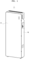
- FIG. 1 an external perspective view showing the battery pack 1 for an energy storage system according to an embodiment of the present disclosure is shown.
- the battery pack 1 has the appearance in the shape of a roughly rectangular parallelepiped cabinet, and a plurality of battery modules 20 and 30 are provided in multiple stages thereinside, and a door 11 may be provided in the front thereof.
- FIG. 2 a perspective view of a battery pack for an energy storage system, having an open door, according to an embodiment of the present disclosure is shown. While the door 11 is open, the battery modules 20 and 30 are provided in three stages inside the battery pack 1, and a control system is provided on the uppermost part thereof.
- FIG. 3 a perspective view of a battery pack for an energy storage system according to an embodiment of the present disclosure is shown before battery modules are assembled inside the battery pack.
- the first support members 70-75 and the second support members 60-66 are provided such that the battery modules 20 and 30 may be provided in three stages.
- the first support members 70-75 are fastened to and supported on the second support members 60-65 and transmit the weight of the battery modules 20 and 30.
- FIGS. 4 and 5 a perspective view of a first elastic support part and a second elastic support part, which are some components of a battery pack for an energy storage system according to an embodiment of the present invention, is shown.
- the first support members 70-75 are provided in a pair at a right angle to a pair of second support members 60-65. Both end of the second support members 60-65 are supported by being fastened to the case 10, and are provided in parallel as a pair, and the first support members 70-75 are fastened and fixed to the upper parts thereof.
- the first support members 70-75 each include a support part and a locking part bent at 90 degrees, and leaf springs 71a, 73a and 75a are included at only one of a pair of first support members 70-75, and the slot 72a is formed in the first support member located opposite thereto.
- the leaf springs 62a, 63a, 64a, 65a, and 66a may be provided on the lower parts of the second support members 62-65, and optionally, the number and location thereof may be determined.
- FIG. 6 a perspective view of a battery pack for an energy storage system according to an embodiment of the present disclosure, of which components therein are assembled, is shown.
- the battery modules 20 and 30 are provided in three stages between the second support members 60-66, and the battery modules 20 and 30 may be provided overlapping in the front and rear directions in every stage. Therefore, referring to FIG.
- the battery modules 20 and 30 may be seated and supported by the second support members 60-66 and the leaf springs 62a, 63a, 64a, 65a, and 66a, and in the left and right directions, the battery modules 20 and 30 may be seated by the first support parts 70-75 and the leaf springs 71a, 73a, and 75a, and in the front and rear directions, the battery modules 20 and 30 may fixed and supported by the middle support part 50 and the front support part 40.
- FIG. 7 an exploded perspective view of a battery pack for an energy storage system according to an embodiment of the present disclosure is shown.
- the battery modules 20 and 30, the middle support part 50, and the front support part 40 on the lowest level are disassembled.
- the battery module 30 in the rear direction is inserted.
- a guide blade 30a of the rear battery module 30 is inserted into the slot 72a of the first support member and is guided, and the opposite side thereof may be elastically supported by the leaf springs 71a, 73a, and 75a.
- the fastening part 50a of the middle support part 50 may be fastened to the case 10, thereby fixing.
- the battery module 20 in the front direction is assembled in the same way, and finally the front support part 40 is fastened and fixed to the second support members 60-66.
- FIGS. 8 and 9 perspective views of a battery pack for an energy storage system according to an embodiment of the present disclosure, viewed from different angles, in which batteries are provided overlapping on the same layer, are shown.
- the lengths of the second support members 60-65 are greater than those of the battery modules 20 and 30, which is designed for installation of battery modules with different specifications, that is, with greater widths.
- the upper parts of the battery modules 20 and 30 are supported by the leaf springs 62a, 63a, 64a, 65a, and 66a, and the lower parts thereof are supported by the first support parts 70-75.
- the left sides of the battery modules 20 and 30 are supported by the leaf springs 71a, 73a, and 75a, and the right sides thereof are supported by locking parts of the first support member 70-75.
- the battery module 30 placed in an inner position is supported by the case 10 and the middle support part 50, and the battery module 20 placed in an outer position may be supported by the middle support part 50 and the front support part 40.
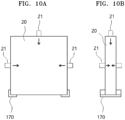
- FIG. 10 is a schematic diagram of a battery pack for an energy storage system according to another embodiment of the present disclosure.
- the lower end of the battery module 20 may be supported by brackets 170 and the battery module 20 is supported by elastic members 21 on the left and right sides
- the schematic diagram shows that the elastic members 21 may be provided in the front and rear directions. In other words, it shows that elastic members may be provided in various positions with respect to three axes depending on design needs.
Landscapes
- Chemical & Material Sciences (AREA)
- Chemical Kinetics & Catalysis (AREA)
- Electrochemistry (AREA)
- General Chemical & Material Sciences (AREA)
- Battery Mounting, Suspending (AREA)
Abstract
Description
- The present disclosure relates to a battery pack structure, and more specifically, to a battery pack for an energy storage system that has ease of assembling and impact absorption.
- In general, batteries are currently used as a device to store electrical energy in many places, and most primary and secondary batteries are cylindrical, prismatic, or pouch. Secondary batteries, which are rechargeable for use, are widely used in portable electronic devices such as smartphones and laptops, as well as electric vehicles that may be rechargeable by using batteries. Recently, battery cells connected in series/parallel are used in an energy storage system (ESS), which stores and uses electricity made from solar energy, wind power, or the like.
- In most cases, methods of connecting cylindrical battery cells in series/parallel include welding cathode and anode terminals of battery cells by using other external connecting plates (Bus Bar). At this time, the current capacity may be increased through a parallel connection (connecting between cathodes and between anodes), and the voltage may be increased through a series connection (connecting a cathode of a battery to an anode of another battery). In most cases, welding is done using a nickel plate, which is a material which is also used in a cathode and an anode of a battery cell. Commonly used electrical devices (from portable to electric vehicles or ESS) are 12 V, 24 V, 48 V, 72 V, 110 V, 200 V, 380 V, or the like, and thus, several to dozens of serial connections are required, and depending on the amount of energy used, several to hundreds or thousands of parallel connections may be also required.
- Conventionally, in the case where a cathode and anode for a battery are connected in series and parallel, a method of connecting a plurality of cells in series and parallel by using spot welding or laser welding, which instantaneously applies voltage between a separate electrode plate and a battery electrode, is used. A battery module refers to a case where the voltage is the same as a single battery cell, but the current capacity is increased. When an (+) electrode of one battery module and an (-) electrode of another battery module, which have the current capacity increased by connecting a plurality of battery cells in parallel, are connected in several times (series connection), the voltage may be increased to a desired level. This is called a battery pack.
- In the case of battery packs of the related art, fastening may be made by restricting 3-axis degrees of freedom of a battery module in three axes of x, y, and z using bolting, rigid materials, or the like. Accordingly, a lot of man-hours are required when fastening. In addition, when external impacts such as earthquakes, drops, or the like are transmitted directly to battery modules, which might cause problems in the battery.
- According to the present disclosure, a battery pack for an energy storage system is provided, in which fixing in some of the axial directions is made using elastic members when installing a battery module, so that an assembly man-hour may be significantly reduced and after installation, stability may be ensured by elastically responding to external impacts.
- A battery pack for an energy storage system according to one aspect of the present disclosure includes a case in which a battery module is placed, a first elastic support part fixed to the inside of the case, allowing opposite lower ends of the battery module to be supported and seated, and including an elastic member, at one side of the lower ends, elastically supporting the battery module toward another side, and a second elastic support part supporting an upper end of the battery module and including, on one side thereof, an elastic member elastically supporting the battery module downward.
- In this regard, the first elastic support part includes a pair of first support members, each of which includes a support part supporting one end of the lower ends of the battery module and a locking part that is bent from the support part to restrict movement of the battery module in a horizontal direction, wherein an elastic member may be provided on one of the locking parts.
- In this regard, a slot is formed in a horizontal direction in the locking part, and a guide blade formed on the battery may be inserted through and guided on the slot.
- In this regard, the second elastic support part includes a second support member disposed on the battery module and horizontally fixed to the case, and an elastic member to elastically support the upper end of the battery module may be provided under the second support member.
- In this regard, the battery module may be provided in multiple stages inside the case.
- In this regard, the first elastic support part may be fixedly provided on the second elastic support part.
- In this regard, the elastic member may be at least one leaf spring.
- In this regard, the battery module may be provided in plurality overlapping in the front and rear directions inside the case, and a plate-shaped middle support part is fixedly assembled to the case to fix and support a rear battery module, between the battery modules, and in the front of a battery module located at the front-most position, a plate-shaped front support part is assembled in the case.
- In this regard, an elastic member may be included between the battery module and the middle support part or between the battery module and the front support part.
- According to the configuration described above, a battery pack for an energy storage system according to the present disclosure may be assembled and fixed easily and quickly because a part of a fastening process using a fastening member may be omitted.
- In addition, a battery pack for an energy storage system according to the present disclosure may alleviate impacts applied to a battery module because when external impacts are applied after the battery module is assembled, an elastic member absorbs part of the impacts.
-
-
FIG. 1 is an external perspective view of a battery pack for an energy storage system according to an embodiment of the present disclosure. -
FIG. 2 is a perspective view of a battery pack for an energy storage system according to an embodiment of the present disclosure, of which a door is open. -
FIG. 3 is a perspective view of a battery pack for an energy storage system according to an embodiment of the present disclosure before battery modules therein are assembled. -
FIG. 4 and5 are perspective views of a first elastic support part and a second elastic support part, which are components of a battery pack for an energy storage system according to an embodiment of the present disclosure. -
FIG. 6 is a perspective view of a battery pack for an energy storage system according to an embodiment of the present disclosure, of which components are assembled. -
FIG. 7 is an exploded perspective view of a battery pack for an energy storage system according to an embodiment of the present disclosure. -
FIG. 8 and9 are perspective views of a battery pack for an energy storage system according to an embodiment of the present disclosure, viewed from different angles, in which batteries are provided overlapping on the same layer. -
FIG. 10 is a schematic diagram of a battery pack for an energy storage system according to another embodiment of the present disclosure. - The words and terms used in this specification and claims are not to be construed as limited in their usual or dictionary meanings, but according to the principle that an inventor may define terms and concepts to explain his or her invention in the best way, they must be construed as meanings and concepts in accord with technical ideas of the present disclosure.
- Therefore, embodiments described in this specification and configurations shown in diagrams correspond to preferred embodiments of the present closure, and do not represent the entire technical idea of the present disclosure, so that corresponding configurations may be replaced by various equivalents and variations at the time of filing of the present disclosure.
- In this specification, the terms "comprise," "include," and/or "have," when used herein, specify the presence of stated features, numbers, steps, operations, components, parts, and/or combinations thereof, but do not preclude possibility of presence or additionality of one or more other features, numbers, steps, operations, components, parts and/or combinations thereof.
- The wording "a component located "front," "rear," "on," or "under" another component" includes not only being located "front," "rear," "on," or "under" in direct contact with the other component, but also a case where another component is placed therebetween, unless there are special circumstances. In addition, the wording that a component is "connected" to the other component includes not only being directly connected to each other, but also indirectly connected to each other, unless there are special circumstances.
- Hereinafter, a battery pack for an energy storage system according to an embodiment of the present disclosure will be described with reference to diagrams.
- A
battery pack 1 for an energy storage system according to an embodiment of the present disclosure may include acase 10, a first elastic support part, a second elastic support part, amiddle support part 50, and afront support part 40. - Referring to
FIGS. 1 to 3 , thecase 10 may includebattery modules - In this regard, the
case 10 may be in the shape of a roughly rectangular parallelepiped cabinet. At the front, adoor 11 may be hinged thereto to allow opening and closing. Within thecase 10, thebattery modules case 10. That is, thebattery modules case 10, and in the present embodiment, may be provided in three stages. Additionally, thebattery modules battery modules middle support part 50 is provided therebetween. - Referring to
FIGS. 2 to 9 , the first elastic support part may be fixed to the inside of thecase 10, allow such that lower ends of thebattery modules elastic members battery modules - In this regard, the first elastic support part includes a pair of locking members 70-75, each including a support part supporting one end of the lower ends of the
battery modules battery modules elastic members - In this regard, a
slot 72a is formed in a horizontal direction in the locking part, andguide blades battery modules slot 72a. - In this regard, the first elastic support part include the first support members 70-75 placed in pairs. The first support members 70-75 may be spaced apart by the width of the
battery modules battery modules battery modules - In this regard, the first support members 70-75 include support parts and locking parts, and the support parts are fixed to the second support members 60-65 by using fastening means. Each locking part is bent vertically from the support part and the lower part of the side of each of the
battery modules leaf springs battery modules guide blades slot 72a, the installation of the lower ends of thebattery modules battery modules - Referring to
FIGS. 2 to 9 , the second elastic support part may support upper ends of thebattery modules elastic members battery modules - In this regard, the second elastic support part includes second support members 60-66 disposed on the
battery modules case 10, and secondelastic members battery modules case 10 or a frame. In this regard, when thebattery modules battery modules - In this regard, the first elastic support part may be fixedly provided on the second elastic support part. That is, first support members 70-75 may be provided and supported on the second support members 60-65. The second support members 60-66 may be fastened to and fixed to the
case 10, and the first support members 70-75 may be fastened to and fixed to the second support members 60-66. Therefore, thebattery modules case 10 through the second support members 60-65 and supported by the same. - In this regard, the
battery modules case 10, and, between thebattery modules middle support part 50 may be fixedly assembled to thecase 10 to fixedly support thebattery module 30 in the rear side thereof, and in front of thebattery module 20 located at the front, a plate-shapedfront support part 40 may be assembled on thecase 10 or thesecond support members FIG. 7 , afastening part 50a may formed on opposite sides of themiddle support part 50 and may be fastened to thecase 10. Accordingly, thebattery module 30 provided on the inside may be fixed in the front and rear directions by themiddle support part 50. In addition, thefront support part 40 may be fastened and fixed to thesecond support members battery module 20 by the fastening members, and thebattery module 20 located in an outer position may be supported while being between thefront support part 40 and themiddle support part 50. - In this regard, an elastic member may be included between the
battery modules middle support part 50 or between thebattery module 20 and thefront support part 40. In this way, for example, by installing a leaf spring between thefront support part 40 and themiddle support part 50, impacts applied to thebattery modules - Referring to
FIG. 1 , an external perspective view showing thebattery pack 1 for an energy storage system according to an embodiment of the present disclosure is shown. Thebattery pack 1 has the appearance in the shape of a roughly rectangular parallelepiped cabinet, and a plurality ofbattery modules door 11 may be provided in the front thereof. - Referring to
FIG. 2 , a perspective view of a battery pack for an energy storage system, having an open door, according to an embodiment of the present disclosure is shown. While thedoor 11 is open, thebattery modules battery pack 1, and a control system is provided on the uppermost part thereof. - Referring to
FIG. 3 , a perspective view of a battery pack for an energy storage system according to an embodiment of the present disclosure is shown before battery modules are assembled inside the battery pack. The first support members 70-75 and the second support members 60-66 are provided such that thebattery modules battery modules - Referring to
FIGS. 4 and5 , a perspective view of a first elastic support part and a second elastic support part, which are some components of a battery pack for an energy storage system according to an embodiment of the present invention, is shown. The first support members 70-75 are provided in a pair at a right angle to a pair of second support members 60-65. Both end of the second support members 60-65 are supported by being fastened to thecase 10, and are provided in parallel as a pair, and the first support members 70-75 are fastened and fixed to the upper parts thereof. The first support members 70-75 each include a support part and a locking part bent at 90 degrees, andleaf springs slot 72a is formed in the first support member located opposite thereto. Theleaf springs - Referring to
FIG. 6 , a perspective view of a battery pack for an energy storage system according to an embodiment of the present disclosure, of which components therein are assembled, is shown. Thebattery modules battery modules FIG. 6 , in up and down directions, thebattery modules leaf springs battery modules leaf springs battery modules middle support part 50 and thefront support part 40. - Referring to
FIG. 7 , an exploded perspective view of a battery pack for an energy storage system according to an embodiment of the present disclosure is shown. Among three stages, thebattery modules middle support part 50, and thefront support part 40 on the lowest level are disassembled. First, thebattery module 30 in the rear direction is inserted. At this time, aguide blade 30a of therear battery module 30 is inserted into theslot 72a of the first support member and is guided, and the opposite side thereof may be elastically supported by theleaf springs fastening part 50a of themiddle support part 50 may be fastened to thecase 10, thereby fixing. Thebattery module 20 in the front direction is assembled in the same way, and finally thefront support part 40 is fastened and fixed to the second support members 60-66. - Referring to
FIGS. 8 and9 , perspective views of a battery pack for an energy storage system according to an embodiment of the present disclosure, viewed from different angles, in which batteries are provided overlapping on the same layer, are shown. In this regard, the lengths of the second support members 60-65 are greater than those of thebattery modules FIGS. 8 and9 , after assembly, in upper and lower directions, the upper parts of thebattery modules leaf springs battery modules leaf springs battery module 30 placed in an inner position is supported by thecase 10 and themiddle support part 50, and thebattery module 20 placed in an outer position may be supported by themiddle support part 50 and thefront support part 40. -
FIG. 10 is a schematic diagram of a battery pack for an energy storage system according to another embodiment of the present disclosure. In the case of (a), which is a schematic diagram of the embodiments described above, the lower end of thebattery module 20 may be supported bybrackets 170 and thebattery module 20 is supported byelastic members 21 on the left and right sides, and in the case of (b), the schematic diagram shows that theelastic members 21 may be provided in the front and rear directions. In other words, it shows that elastic members may be provided in various positions with respect to three axes depending on design needs. - Although the embodiments of the present disclosure have been described, the spirit of the present disclosure is not limited to the embodiments presented in this specification, and those skilled in the art who understand the spirit of the present disclosure may easily suggest other embodiments by additions, changes, deletions, supplements of components, but this will also be deemed to fall within the scope of the present disclosure.
- The present disclosure may be applied to a battery pack for an energy storage system.
Claims (9)
- A battery pack for an energy storage system, the battery pack comprising: a case in which a battery module is placed, a first elastic support part fixed to the inside of the case, allowing opposite lower ends of the battery module to be supported and seated, and including an elastic member, at one side of the lower ends, elastically supporting the battery module toward another side, and a second elastic support part supporting an upper end of the battery module and including, on one side thereof, an elastic member elastically supporting the battery module downward.
- The battery pack for an energy storage system of claim 1, wherein the first elastic support part comprises a pair of first support members each including a support part supporting one of the lower ends of the battery module and a locking part bent from the support part to restrict movement of the battery module in a horizontal direction, wherein an elastic member is included on one of the locking parts.
- The battery pack for an energy storage system of claim 2, wherein a slot is formed in a horizontal direction in the locking part, and a guide blade formed on the battery is inserted therethrough and guided on the slot.
- The battery pack for an energy storage system of claim 1, wherein the second elastic support part comprises a second support member disposed on the battery module and horizontally fixed to the case, and an elastic member is included under the second support member to elastically support the upper part of the battery module.
- The battery pack for an energy storage system of claim 1, wherein the battery module is provided in multiple stages within the case.
- The battery pack for an energy storage system of claim 5, wherein the first elastic support part is fixedly provided on the second elastic support part.
- The battery pack for an energy storage system of claim 1, wherein the elastic member is at least one leaf spring.
- The battery pack for an energy storage system of claim 1, wherein the battery module is provided in plurality overlapping in front and rear directions within the case, and between the battery modules, a middle support part formed in a plate-shape is fixedly assembled to the case to fixedly support a battery module in a rear side, and in the front of a battery module located at the front-most position, a front support part in a plate-shape is assembled in the case.
- The battery pack for an energy storage system of claim 8, wherein an elastic member is included between the battery module and the middle support part or between the battery module and the front support part.
Applications Claiming Priority (2)
| Application Number | Priority Date | Filing Date | Title |
|---|---|---|---|
| KR1020220010564A KR102764401B1 (en) | 2022-01-25 | 2022-01-25 | Battery pack for energy storage system |
| PCT/KR2023/000843 WO2023146202A1 (en) | 2022-01-25 | 2023-01-18 | Energy storage system battery pack |
Publications (2)
| Publication Number | Publication Date |
|---|---|
| EP4447209A1 true EP4447209A1 (en) | 2024-10-16 |
| EP4447209A4 EP4447209A4 (en) | 2025-04-23 |
Family
ID=87471868
Family Applications (1)
| Application Number | Title | Priority Date | Filing Date |
|---|---|---|---|
| EP23747244.4A Pending EP4447209A4 (en) | 2022-01-25 | 2023-01-18 | ENERGY STORAGE SYSTEM BATTERY PACK |
Country Status (4)
| Country | Link |
|---|---|
| US (1) | US20250096392A1 (en) |
| EP (1) | EP4447209A4 (en) |
| KR (1) | KR102764401B1 (en) |
| WO (1) | WO2023146202A1 (en) |
Families Citing this family (2)
| Publication number | Priority date | Publication date | Assignee | Title |
|---|---|---|---|---|
| KR20250135969A (en) * | 2024-03-07 | 2025-09-16 | 주식회사 엘지에너지솔루션 | Energy storage system including battery modules |
| KR20250135968A (en) * | 2024-03-07 | 2025-09-16 | 주식회사 엘지에너지솔루션 | Energy storage system including battery modules |
Family Cites Families (12)
| Publication number | Priority date | Publication date | Assignee | Title |
|---|---|---|---|---|
| KR200313243Y1 (en) * | 1997-10-24 | 2003-08-21 | 현대자동차주식회사 | Battery mounting structure |
| KR200452429Y1 (en) * | 2009-09-10 | 2011-02-25 | 이종녕 | Seismic Battery Base |
| US8900737B2 (en) * | 2011-09-08 | 2014-12-02 | Samsung Sdi Co., Ltd. | Energy storage system |
| US20130071705A1 (en) * | 2011-09-16 | 2013-03-21 | General Electric Company | Structure, packaging assembly, and cover for multi-cell array batteries |
| KR101301559B1 (en) * | 2013-01-16 | 2013-09-04 | 주식회사 이브텍 | Battery case |
| KR101495227B1 (en) * | 2013-09-12 | 2015-02-24 | 송암시스콤 주식회사 | Portable battery |
| FR3011776B1 (en) * | 2013-10-16 | 2017-04-14 | Blue Solutions | ELECTRIC ENERGY STORAGE ASSEMBLY AND METHOD OF ASSEMBLING SUCH ASSEMBLY |
| KR101726767B1 (en) * | 2014-11-17 | 2017-04-13 | 주식회사 엘지화학 | Battery Pack Having Elastic Rib for Fixing Battery Cell |
| CN210576089U (en) * | 2019-09-09 | 2020-05-19 | 天津泰策精能科技有限公司 | Anti-shaking electric heating standby power supply device convenient to install |
| KR102097779B1 (en) * | 2019-09-25 | 2020-04-07 | 송주환 | Household Energy Storage System |
| CN212366090U (en) * | 2020-07-16 | 2021-01-15 | 深圳市凯曼达科技有限公司 | An industrial supporting lithium battery pack with efficient heat dissipation |
| CN213459926U (en) * | 2020-08-27 | 2021-06-15 | 江苏葑全新能源动力科技有限公司 | Cylindrical lithium ion battery module fixing frame |
-
2022
- 2022-01-25 KR KR1020220010564A patent/KR102764401B1/en active Active
-
2023
- 2023-01-18 US US18/832,808 patent/US20250096392A1/en active Pending
- 2023-01-18 WO PCT/KR2023/000843 patent/WO2023146202A1/en not_active Ceased
- 2023-01-18 EP EP23747244.4A patent/EP4447209A4/en active Pending
Also Published As
| Publication number | Publication date |
|---|---|
| US20250096392A1 (en) | 2025-03-20 |
| KR102764401B1 (en) | 2025-02-07 |
| EP4447209A4 (en) | 2025-04-23 |
| WO2023146202A1 (en) | 2023-08-03 |
| KR20230114432A (en) | 2023-08-01 |
Similar Documents
| Publication | Publication Date | Title |
|---|---|---|
| EP2328201B1 (en) | Battery Pack | |
| EP3664186A1 (en) | Battery module, and battery pack and vehicle comprising same | |
| EP3709388B1 (en) | Battery pack including connection plate | |
| EP4447209A1 (en) | Energy storage system battery pack | |
| EP2393141A2 (en) | Cell cartridge with a composite intercell connecting net structure | |
| EP3288098B1 (en) | Battery module, battery pack including battery module, and automobile including battery pack | |
| EP4142030B1 (en) | Battery rack, energy storage system, and power generation system | |
| US10367180B2 (en) | Battery pack | |
| EP4145601A1 (en) | Battery rack, power storage device, and power generation system | |
| CN102187512A (en) | Lithium storage battery unit pack with bus bars and lithium storage battery pack with bus bars | |
| EP4037059A1 (en) | Sub pack comprising multiple unit modules and bms assembly, and battery pack comprising same | |
| US11870091B2 (en) | Battery pack and energy storage system including the same | |
| EP4465424A2 (en) | Cell stack assembly, and battery pack comprising cell stack assembly | |
| KR20200086171A (en) | Electrode lead tack welding jig of battery cell | |
| EP4071903A1 (en) | Battery pack and vehicle comprising same | |
| US20200411831A1 (en) | Connector and battery module including the same | |
| CN100477335C (en) | Battery and assembled rack battery system | |
| US20210218097A1 (en) | Battery Module | |
| CN117957709A (en) | Battery | |
| EP4421967A1 (en) | Battery module comprising upper/lower-separable bus bar frame, and method for assembling same | |
| CN222801947U (en) | Battery rack, battery container comprising battery rack and energy storage system | |
| EP4737668A1 (en) | Door locking device of energy storage apparatus | |
| EP4708499A1 (en) | Energy storage device comprising battery modules | |
| US20250379314A1 (en) | Structure and method for fixing battery module to battery pack | |
| US20220255192A1 (en) | Assembly set for assembling a carrier framework for a stack of battery cell blocks |
Legal Events
| Date | Code | Title | Description |
|---|---|---|---|
| STAA | Information on the status of an ep patent application or granted ep patent |
Free format text: STATUS: THE INTERNATIONAL PUBLICATION HAS BEEN MADE |
|
| PUAI | Public reference made under article 153(3) epc to a published international application that has entered the european phase |
Free format text: ORIGINAL CODE: 0009012 |
|
| STAA | Information on the status of an ep patent application or granted ep patent |
Free format text: STATUS: REQUEST FOR EXAMINATION WAS MADE |
|
| 17P | Request for examination filed |
Effective date: 20240712 |
|
| AK | Designated contracting states |
Kind code of ref document: A1 Designated state(s): AL AT BE BG CH CY CZ DE DK EE ES FI FR GB GR HR HU IE IS IT LI LT LU LV MC ME MK MT NL NO PL PT RO RS SE SI SK SM TR |
|
| STAA | Information on the status of an ep patent application or granted ep patent |
Free format text: STATUS: EXAMINATION IS IN PROGRESS |
|
| A4 | Supplementary search report drawn up and despatched |
Effective date: 20250324 |
|
| RIC1 | Information provided on ipc code assigned before grant |
Ipc: H01M 50/209 20210101ALI20250318BHEP Ipc: H01M 50/291 20210101ALI20250318BHEP Ipc: H01M 50/289 20210101ALI20250318BHEP Ipc: H01M 50/262 20210101ALI20250318BHEP Ipc: H01M 50/258 20210101ALI20250318BHEP Ipc: H01M 50/251 20210101ALI20250318BHEP Ipc: H01M 50/244 20210101ALI20250318BHEP Ipc: H01M 50/242 20210101ALI20250318BHEP Ipc: H01M 50/204 20210101AFI20250318BHEP |
|
| DAV | Request for validation of the european patent (deleted) | ||
| DAX | Request for extension of the european patent (deleted) | ||
| 17Q | First examination report despatched |
Effective date: 20250404 |