EP4447142A1 - Cell and electronic device - Google Patents
Cell and electronic device Download PDFInfo
- Publication number
- EP4447142A1 EP4447142A1 EP23217653.7A EP23217653A EP4447142A1 EP 4447142 A1 EP4447142 A1 EP 4447142A1 EP 23217653 A EP23217653 A EP 23217653A EP 4447142 A1 EP4447142 A1 EP 4447142A1
- Authority
- EP
- European Patent Office
- Prior art keywords
- negative electrode
- electrode film
- positive electrode
- active substance
- film
- Prior art date
- Legal status (The legal status is an assumption and is not a legal conclusion. Google has not performed a legal analysis and makes no representation as to the accuracy of the status listed.)
- Granted
Links
Images
Classifications
-
- H—ELECTRICITY
- H01—ELECTRIC ELEMENTS
- H01M—PROCESSES OR MEANS, e.g. BATTERIES, FOR THE DIRECT CONVERSION OF CHEMICAL ENERGY INTO ELECTRICAL ENERGY
- H01M4/00—Electrodes
- H01M4/02—Electrodes composed of, or comprising, active material
- H01M4/04—Processes of manufacture in general
- H01M4/0402—Methods of deposition of the material
- H01M4/0404—Methods of deposition of the material by coating on electrode collectors
-
- H—ELECTRICITY
- H01—ELECTRIC ELEMENTS
- H01M—PROCESSES OR MEANS, e.g. BATTERIES, FOR THE DIRECT CONVERSION OF CHEMICAL ENERGY INTO ELECTRICAL ENERGY
- H01M10/00—Secondary cells; Manufacture thereof
- H01M10/05—Accumulators with non-aqueous electrolyte
- H01M10/052—Li-accumulators
- H01M10/0525—Rocking-chair batteries, i.e. batteries with lithium insertion or intercalation in both electrodes; Lithium-ion batteries
-
- H—ELECTRICITY
- H01—ELECTRIC ELEMENTS
- H01M—PROCESSES OR MEANS, e.g. BATTERIES, FOR THE DIRECT CONVERSION OF CHEMICAL ENERGY INTO ELECTRICAL ENERGY
- H01M4/00—Electrodes
- H01M4/02—Electrodes composed of, or comprising, active material
- H01M4/13—Electrodes for accumulators with non-aqueous electrolyte, e.g. for lithium-accumulators; Processes of manufacture thereof
- H01M4/131—Electrodes based on mixed oxides or hydroxides, or on mixtures of oxides or hydroxides, e.g. LiCoOx
-
- H—ELECTRICITY
- H01—ELECTRIC ELEMENTS
- H01M—PROCESSES OR MEANS, e.g. BATTERIES, FOR THE DIRECT CONVERSION OF CHEMICAL ENERGY INTO ELECTRICAL ENERGY
- H01M4/00—Electrodes
- H01M4/02—Electrodes composed of, or comprising, active material
- H01M4/13—Electrodes for accumulators with non-aqueous electrolyte, e.g. for lithium-accumulators; Processes of manufacture thereof
- H01M4/133—Electrodes based on carbonaceous material, e.g. graphite-intercalation compounds or CFx
-
- H—ELECTRICITY
- H01—ELECTRIC ELEMENTS
- H01M—PROCESSES OR MEANS, e.g. BATTERIES, FOR THE DIRECT CONVERSION OF CHEMICAL ENERGY INTO ELECTRICAL ENERGY
- H01M4/00—Electrodes
- H01M4/02—Electrodes composed of, or comprising, active material
- H01M4/13—Electrodes for accumulators with non-aqueous electrolyte, e.g. for lithium-accumulators; Processes of manufacture thereof
- H01M4/134—Electrodes based on metals, Si or alloys
-
- H—ELECTRICITY
- H01—ELECTRIC ELEMENTS
- H01M—PROCESSES OR MEANS, e.g. BATTERIES, FOR THE DIRECT CONVERSION OF CHEMICAL ENERGY INTO ELECTRICAL ENERGY
- H01M4/00—Electrodes
- H01M4/02—Electrodes composed of, or comprising, active material
- H01M4/36—Selection of substances as active materials, active masses, active liquids
- H01M4/362—Composites
- H01M4/366—Composites as layered products
-
- H—ELECTRICITY
- H01—ELECTRIC ELEMENTS
- H01M—PROCESSES OR MEANS, e.g. BATTERIES, FOR THE DIRECT CONVERSION OF CHEMICAL ENERGY INTO ELECTRICAL ENERGY
- H01M4/00—Electrodes
- H01M4/02—Electrodes composed of, or comprising, active material
- H01M4/36—Selection of substances as active materials, active masses, active liquids
- H01M4/38—Selection of substances as active materials, active masses, active liquids of elements or alloys
- H01M4/386—Silicon or alloys based on silicon
-
- H—ELECTRICITY
- H01—ELECTRIC ELEMENTS
- H01M—PROCESSES OR MEANS, e.g. BATTERIES, FOR THE DIRECT CONVERSION OF CHEMICAL ENERGY INTO ELECTRICAL ENERGY
- H01M4/00—Electrodes
- H01M4/02—Electrodes composed of, or comprising, active material
- H01M4/36—Selection of substances as active materials, active masses, active liquids
- H01M4/48—Selection of substances as active materials, active masses, active liquids of inorganic oxides or hydroxides
- H01M4/50—Selection of substances as active materials, active masses, active liquids of inorganic oxides or hydroxides of manganese
- H01M4/505—Selection of substances as active materials, active masses, active liquids of inorganic oxides or hydroxides of manganese of mixed oxides or hydroxides containing manganese for inserting or intercalating light metals, e.g. LiMn2O4 or LiMn2OxFy
-
- H—ELECTRICITY
- H01—ELECTRIC ELEMENTS
- H01M—PROCESSES OR MEANS, e.g. BATTERIES, FOR THE DIRECT CONVERSION OF CHEMICAL ENERGY INTO ELECTRICAL ENERGY
- H01M4/00—Electrodes
- H01M4/02—Electrodes composed of, or comprising, active material
- H01M4/36—Selection of substances as active materials, active masses, active liquids
- H01M4/48—Selection of substances as active materials, active masses, active liquids of inorganic oxides or hydroxides
- H01M4/52—Selection of substances as active materials, active masses, active liquids of inorganic oxides or hydroxides of nickel, cobalt or iron
- H01M4/525—Selection of substances as active materials, active masses, active liquids of inorganic oxides or hydroxides of nickel, cobalt or iron of mixed oxides or hydroxides containing iron, cobalt or nickel for inserting or intercalating light metals, e.g. LiNiO2, LiCoO2 or LiCoOxFy
-
- H—ELECTRICITY
- H01—ELECTRIC ELEMENTS
- H01M—PROCESSES OR MEANS, e.g. BATTERIES, FOR THE DIRECT CONVERSION OF CHEMICAL ENERGY INTO ELECTRICAL ENERGY
- H01M4/00—Electrodes
- H01M4/02—Electrodes composed of, or comprising, active material
- H01M4/36—Selection of substances as active materials, active masses, active liquids
- H01M4/58—Selection of substances as active materials, active masses, active liquids of inorganic compounds other than oxides or hydroxides, e.g. sulfides, selenides, tellurides, halogenides or LiCoFy; of polyanionic structures, e.g. phosphates, silicates or borates
- H01M4/5825—Oxygenated metallic salts or polyanionic structures, e.g. borates, phosphates, silicates, olivines
-
- H—ELECTRICITY
- H01—ELECTRIC ELEMENTS
- H01M—PROCESSES OR MEANS, e.g. BATTERIES, FOR THE DIRECT CONVERSION OF CHEMICAL ENERGY INTO ELECTRICAL ENERGY
- H01M4/00—Electrodes
- H01M4/02—Electrodes composed of, or comprising, active material
- H01M4/36—Selection of substances as active materials, active masses, active liquids
- H01M4/58—Selection of substances as active materials, active masses, active liquids of inorganic compounds other than oxides or hydroxides, e.g. sulfides, selenides, tellurides, halogenides or LiCoFy; of polyanionic structures, e.g. phosphates, silicates or borates
- H01M4/583—Carbonaceous material, e.g. graphite-intercalation compounds or CFx
- H01M4/587—Carbonaceous material, e.g. graphite-intercalation compounds or CFx for inserting or intercalating light metals
-
- H—ELECTRICITY
- H01—ELECTRIC ELEMENTS
- H01M—PROCESSES OR MEANS, e.g. BATTERIES, FOR THE DIRECT CONVERSION OF CHEMICAL ENERGY INTO ELECTRICAL ENERGY
- H01M50/00—Constructional details or processes of manufacture of the non-active parts of electrochemical cells other than fuel cells, e.g. hybrid cells
- H01M50/40—Separators; Membranes; Diaphragms; Spacing elements inside cells
- H01M50/46—Separators, membranes or diaphragms characterised by their combination with electrodes
-
- H—ELECTRICITY
- H01—ELECTRIC ELEMENTS
- H01M—PROCESSES OR MEANS, e.g. BATTERIES, FOR THE DIRECT CONVERSION OF CHEMICAL ENERGY INTO ELECTRICAL ENERGY
- H01M4/00—Electrodes
- H01M4/02—Electrodes composed of, or comprising, active material
- H01M2004/021—Physical characteristics, e.g. porosity, surface area
-
- H—ELECTRICITY
- H01—ELECTRIC ELEMENTS
- H01M—PROCESSES OR MEANS, e.g. BATTERIES, FOR THE DIRECT CONVERSION OF CHEMICAL ENERGY INTO ELECTRICAL ENERGY
- H01M4/00—Electrodes
- H01M4/02—Electrodes composed of, or comprising, active material
- H01M2004/026—Electrodes composed of, or comprising, active material characterised by the polarity
- H01M2004/028—Positive electrodes
-
- Y—GENERAL TAGGING OF NEW TECHNOLOGICAL DEVELOPMENTS; GENERAL TAGGING OF CROSS-SECTIONAL TECHNOLOGIES SPANNING OVER SEVERAL SECTIONS OF THE IPC; TECHNICAL SUBJECTS COVERED BY FORMER USPC CROSS-REFERENCE ART COLLECTIONS [XRACs] AND DIGESTS
- Y02—TECHNOLOGIES OR APPLICATIONS FOR MITIGATION OR ADAPTATION AGAINST CLIMATE CHANGE
- Y02E—REDUCTION OF GREENHOUSE GAS [GHG] EMISSIONS, RELATED TO ENERGY GENERATION, TRANSMISSION OR DISTRIBUTION
- Y02E60/00—Enabling technologies; Technologies with a potential or indirect contribution to GHG emissions mitigation
- Y02E60/10—Energy storage using batteries
Definitions
- the disclosure relates to a cell and an electronic device.
- the weight energy density of conventional lithium iron phosphate power cells is generally 160 to 190 Wh/kg.
- lithium manganese iron phosphate has a theoretical capacity comparable to lithium iron phosphate and has a higher voltage platform and can thus provide higher energy density, but it is still difficult to exceed 200 Wh/kg.
- the energy density of ternary lithium-ion batteries is higher, their high price and thermal safety make consumers somewhat hesitant.
- the industry chooses to use phosphate positive electrode materials together with high energy density positive electrode materials such as ternary positive electrodes, lithium-rich manganese-based positive electrodes, etc.
- phosphate positive electrodes and ternary materials are used by mixing internally in a slurry. Since phosphate has poor conductivity, more conductive agent is required. Also, the specific surface area is large, so more binder is required. As a result, the proportion of the main material in the electrode plate is low, which affects the total energy density of the cell. At the same time, phosphate positive electrode materials with low ionic conductivity and electronic conductivity may adsorb on the surface of ternary materials, which affects the capacity performance of the ternary materials.
- materials such as lithium iron phosphate, lithium manganese iron phosphate, ternary positive electrode materials, and lithium-rich manganese-based materials each have more matching negative electrode graphite materials. If a mixed positive electrode is used, it will pose new challenges to the selection of graphite.
- the disclosure provides a cell and an electronic device.
- the positive electrode and the negative electrode in the cell of the disclosure are reasonably matched, which can maximize the performances of total energy density and capacity of the cell while taking safety into account.
- the disclosure addresses the above technical problems mainly by the following technical solutions.
- the disclosure provides a cell including a positive electrode plate and a negative electrode plate alternately arranged along a cell thickness direction, with a separator provided between the positive electrode plate and the negative electrode plate.
- the positive electrode plate includes a positive electrode current collector, a first positive electrode film, and a second positive electrode film, and the first positive electrode film and the second positive electrode film are respectively arranged on two opposite surfaces of the positive electrode current collector.
- the first positive electrode film includes a first positive electrode active substance that includes a phosphate material
- the second positive electrode film includes a second positive electrode active substance that has a gram capacity greater than a gram capacity of the first positive electrode active substance.
- the negative electrode plate includes a negative electrode current collector, a first negative electrode film, and a second negative electrode film, and the first negative electrode film and the second negative electrode film are respectively arranged on two opposite surfaces of the negative electrode current collector.
- the first negative electrode film includes a first negative electrode active substance
- the second negative electrode film includes a second negative electrode active substance
- OI 2 -OI>5 is satisfied, where OI 2 is an OI value of the second negative electrode film, and OI 1 is an OI value of the first negative electrode film.
- the disclosure further provides an electronic device including the cell described above.
- the positive progressive effects of the disclosure are as follows.
- the disclosure selects different positive electrode formulations for different negative electrode formulations to maximize matching in the mixing system and achieve a combination of high energy density, high safety, and low costs.
- the two surfaces of the positive electrode respectively adopt a phosphate material and a high density active substance, which respectively correspond in a one-to-one manner to a high energy density film and a fast charging high kinetics film of the negative electrode.
- the positive and negative electrodes match each other to achieve a balance between energy density and fast charging performance.
- the first positive electrode film is adjacent to the second negative electrode film via a separator
- the second positive electrode film is adjacent to the first negative electrode film via a separator
- the phosphate material may be a positive electrode phosphate material commonly used in this field, preferably lithium iron phosphate and/or lithium manganese iron phosphate.
- the use of the phosphate material can reduce the system cost and improve safety performance.
- the mass content of the phosphate material is 92% to 97%, for example, 94% or 95%.
- the discharge gram capacity of the phosphate material at a current density of 0.1C is 160 mAh/g or below, more preferably 127 to 160 mAh/g, for example, 141 mAh/g or 157 mAh/g.
- the second positive electrode active substance is a high energy density active substance commonly used in this field, and its use can enhance the energy density and low temperature cycling performance of the battery.
- the second positive electrode active substance includes one or more of lithium manganate, lithium cobalt oxide, lithium nickelate, lithium nickel cobalt aluminum oxide, lithium nickel cobalt manganese oxide, and lithium-rich manganese-based materials.
- the second positive electrode active substance includes lithium nickel cobalt aluminum oxide or lithium nickel cobalt manganese oxide
- the mass content of Ni is 60% or more.
- the content of the second positive electrode active substance is 94% to 98%, for example, 96%.
- the discharge gram capacity of the second positive electrode active substance at a current density of 0.1C is 180 mAh/g or more, more preferably 180 to 210 mAh/g, for example, 198 mAh/g.
- the content of the second positive electrode active substance is greater than the content of the first positive electrode active substance.
- the first positive electrode active substance is lithium manganese iron phosphate
- the second positive electrode active substance is lithium nickel cobalt manganese oxide
- the lithium manganese iron phosphate is preferably LiMn 0.6 Fe 0.4 PO 4
- the lithium nickel cobalt manganese oxide is preferably LiNi 0.8 Co 0.1 Mn 0.1 O 2 .
- the first positive electrode active substance is lithium iron phosphate
- the second positive electrode active substance is lithium nickel cobalt manganese oxide
- the lithium iron phosphate is preferably LiFePO 4
- the lithium nickel cobalt manganese oxide is preferably LiNi 0.8 Co 0.1 Mn 0.1 O 2 .
- the thickness ratio of the first positive electrode film to the second positive electrode film is preferably (1.1 to 2.5), for example, 1.98: 1 or 1.63: 1.
- the thickness of the first positive electrode film may be 50 to 120 ⁇ m, preferably 60 to 100 ⁇ m, for example, 76 ⁇ m or 91 ⁇ m.
- the thickness of the second positive electrode film may be 30 to 90 ⁇ m, preferably 40 to 70 ⁇ m, for example, 47 ⁇ m.
- positive electrode active substances of different capacities are selected, which require negative electrode materials with matching capacities.
- an appropriate thickness ratio is selected, it is possible to control the thickness difference between the front and back surfaces of the negative electrode to be small, which is beneficial for the processing of the negative electrode.
- the thickness described in the disclosure is calculated according to the following method.
- the thickness of the first positive electrode film be hi, the specific discharge capacity of the first positive electrode film be x 1 , and the specific discharge capacity of the second negative electrode film be x 2 ; the proportion of the first positive electrode active substance be y 1 , the proportion of the second negative electrode active substance be y 2 , the compacted density of the first positive electrode film after rolling be zi, and the compacted density of the second negative electrode film after rolling be z 2 ; and N/P be a 1 .
- the thickness h 2 of the second negative electrode film is a 1 ⁇ x 1 ⁇ y 1 ⁇ z 1 ⁇ h 1 x 2 ⁇ y 2 ⁇ z 2 .
- the thickness of the second positive electrode film be hs
- the specific discharge capacity of the second positive electrode film be x 3
- the specific discharge capacity of the first negative electrode film be x 4
- the proportion of the second positive electrode active substance be y 3
- the proportion of the first negative electrode active substance be y 4
- the compacted density of the second positive electrode film after rolling be z 3
- the compacted density of the first electrode film after rolling be z4
- N/P be a2.
- the thickness h4 of the first negative electrode film is a 2 ⁇ x 3 ⁇ y 3 ⁇ z 3 ⁇ h 3 x 4 ⁇ y 4 ⁇ z 4 .
- N/P may be 1.02 to 1.14, and a 1 ⁇ a 2 .
- the N/P which stands for negative/positive, is "capacity of negative electrode per unit area/capacity of positive electrode per unit area", and is generally a ratio of charging capacity.
- the thickness of the first positive electrode film is 50 to 120 ⁇ m; the compacted density of the first positive electrode film is 2.2 to 2.6 g/cm 3 ; the thickness of the second positive electrode film is 30 to 90 ⁇ m; and the compacted density of the second positive electrode film is 3.3 to 3.7 g/cm 3 .
- the first positive electrode film generally further includes a first positive electrode conductive agent, a first positive electrode binder, and a first positive electrode dispersant; and the second positive electrode film generally further includes a second positive electrode conductive agent, a second positive electrode binder, and a second positive electrode dispersant.
- first positive electrode conductive agent and the second positive electrode conductive agent are conductive and do not cause chemical changes in the battery.
- Specific examples include: graphite, such as natural graphite or artificial graphite; carbon-based materials, such as carbon black, acetylene black, Ketjen black, channel black, furnace black, lamp black, thermal carbon black, and carbon fibers; metal powders or metal fibers, such as copper, nickel, aluminum, and silver; conductive whiskers, such as zinc oxide whiskers and potassium titanate whiskers; conductive metal oxides, such as titanium dioxide; or conductive polymers, such as polyphenylene derivatives, etc.
- the content of the first conductive agent is preferably 1% to 3%, for example, 2%, where the percentage is the percentage of the mass of the first conductive agent in the mass of the first positive electrode film.
- the mass ratio of the second conductive agent is preferably 0.5% to 2%, for example, 1.5%, where the percentage is the percentage of the mass of the second conductive agent in the mass of the second positive electrode film.
- the first positive electrode binder and the second positive electrode binder serve to enhance the binding between the positive electrode active substance particles and the adhesion between the positive electrode active substance and the positive electrode current collector.
- the binders may include polyvinylidene fluoride (PVDF), polyvinylidene fluoride-co-hexafluoropropylene (PVDF-co-HFP), polyvinyl alcohol, polyacrylonitrile, carboxymethyl cellulose (CMC), starch, hydroxypropyl cellulose, regenerated cellulose, polyvinylpyrrolidone, tetrafluoroethylene, polyethylene, polypropylene, ethylene-propylene-diene monomer (EPDM), sulfonated EPDM, styrene-butadiene rubber (SBR), fluororubber, or various copolymers thereof, and any one or a mixture of two or more of the above may be used.
- PVDF polyvinylidene fluoride
- the content of the first binder is preferably 1.5% to 4%, for example, 3.5%, where the percentage is the percentage of the mass of the first binder in the mass of the first positive electrode film.
- the mass ratio of the second binder is preferably 0.5% to 2%, where the percentage is the percentage of the mass of the second binder in the mass of the second positive electrode film.
- the content of the second positive electrode binder is lower than the content of the first positive electrode binder.
- the first dispersant and the second dispersant may be substances commonly used in this field to improve dispersion uniformity of the active substances.
- the content of the first dispersant may be 0 to 1%, where the percentage is the percentage of the mass of the first dispersant in the mass of the first positive electrode film.
- the content of the second dispersant may be 0 to 1%, where the percentage is the percentage of the mass of the second dispersant in the mass of the second positive electrode film.
- the method for preparing the positive electrode plate includes the following steps: coating the raw material mixture of the first positive electrode film and the raw material mixture of the second positive electrode film respectively on two surfaces of the positive electrode current collector to obtain the positive electrode plate.
- the surface density generally refers to the mass of the raw material mixture coated per unit area, and refers to one surface.
- the surface densities of the first positive electrode film and the second positive electrode film may be 15 to 32 mg/cm 2 , preferably 20 to 25 mg/cm 2 , for example, 22 mg/cm 2 .
- the surface density of the second positive electrode film is less than the surface density of the first positive electrode film.
- the surface density of the raw material composition of the second positive electrode film during coating is 60% to 95% of the surface density of the raw material composition of the first positive electrode film during coating.
- the OI value refers to the degree of orientation, which may be calculated based on data measured by XRD.
- the OI value is a ratio of the peak area of the 004 characteristic peak in the X-ray diffraction spectrum of the negative electrode film to the peak area of the 110 characteristic peak in the X-ray diffraction spectrum of the negative electrode film.
- OI 1 C 004 /C 110 , where C 004 is the peak area of the 004 characteristic diffraction peak in the X-ray diffraction spectrum of the first negative electrode film; and C 110 is the peak area of the 110 characteristic diffraction peak in the X-ray diffraction spectrum of the first negative electrode film.
- OI 2 C' 004 /C' 110 , where C' 004 is the peak area of the 004 characteristic diffraction peak in the X-ray diffraction spectrum of the second negative electrode film; and C' 110 is the peak area of the 110 characteristic diffraction peak in the X-ray diffraction spectrum of the second negative electrode film.
- XRD is measured with Bruker D8A25 X-ray diffractometer.
- the magnitude of the OI value of the negative electrode film may reflect the degree of stacking orientation of the negative electrode active material particles in the negative electrode film, which directly affects the expansion of the negative electrode plate in the cycling process.
- lithium ions are de-intercalated from the positive electrode active substance and intercalated in the negative electrode active substance, so the OI value of the negative electrode film has a great impact on the charging speed and cycle life of the lithium-ion battery.
- the high energy active substance has advantages of high gram capacity and high degree of orientation and can contribute to higher energy density.
- active substances with high OI and low OI are mixed and used together, but the mixture of low OI value with high OI generally fails to create excellent rate capability and high kinetics performance.
- active substances with high OI and low OI values are respectively coated on two opposite surfaces of the negative electrode current collector, which can balance the combination of high kinetics and energy density.
- the OI value OI 1 of the first negative electrode film is 2 to 15, preferably 4 to 10.
- the OI value OI 2 in the second negative electrode film is 15 to 50, preferably 15 to 40.
- the OI 2 -OI 1 is 5 to 15, for example, 12 or 14.
- the first negative electrode active substance and the second negative electrode active substance may each independently include one or two of graphite and silicon materials.
- the graphite includes natural graphite or artificial graphite; and the silicon materials include at least one of silicon-carbon material or carbon-silicon-oxygen material.
- the silicon-carbon material refers to a material that contains both silicon element and carbon element.
- the silicon-carbon material has a structure in which silicon nanocrystal particles are filled in pores of a carbon skeleton.
- the silicon-oxygen-carbon material refers to a material that contains silicon element, oxygen element, and carbon element at the same time.
- the silicon-oxygen-carbon material has as structure in which silicon nanocrystal particles are dispersed in a silicon dioxide matrix to form a composite, and elemental carbon is wrapped on the outer surface of the composite.
- the mass content of the first negative electrode active substance is 93 to 98%, for example, 96%.
- the first negative electrode film may further include 0.2 to 1.5% of a first negative electrode conductive agent, 1 to 3% of a first negative electrode binder, and 0.01 to 1.5% of a first negative electrode dispersant.
- the mass content of the second negative electrode active substance is preferably 95 to 98.5%, for example, 95%.
- the types of the first negative electrode active substance and the second negative electrode active substance are the same as each other, and the mass content of the first negative electrode active substance is lower than the mass content of the second negative electrode active substance.
- the mass contents of the first negative electrode active substance and the second negative electrode active substance satisfy the above conditions, the capacity retention rate of the battery can be effectively improved.
- the second negative electrode film may further include 0.2 to 1.5% of a second negative electrode conductive agent, 0.5 to 2% of a second negative electrode binder, and 0.01 to 1.5% of a second negative electrode dispersant.
- the first negative electrode conductive agent and the second negative electrode conductive agent are reagents used to ensure that the electrode has good charge and discharge performance. They may be selected from any of graphite materials such as natural graphite and artificial graphite, carbon black materials such as carbon black, acetylene black, Ketjen black, channel black, furnace black, lamp black, and thermal carbon black, conductive fibers such as carbon fibers and metal fibers, metal powders such as fluorocarbon powder, aluminum powder, and nickel powder, conductive whiskers such as zinc oxide, potassium titanate, and conductive metal oxides such as titanium dioxide, or polyphenylene derivatives.
- graphite materials such as natural graphite and artificial graphite
- carbon black materials such as carbon black, acetylene black, Ketjen black, channel black, furnace black, lamp black, and thermal carbon black
- conductive fibers such as carbon fibers and metal fibers
- metal powders such as fluorocarbon powder, aluminum powder, and nickel powder
- conductive whiskers such as zinc oxide, potassium
- the first negative electrode binder and the second negative electrode binder are components that contribute to binding between the active substance and the conductive agent and contribute to combination of the active substance with the current collector. They may generally be selected from polyvinylidene difluoride, polyvinyl alcohol, carboxymethyl cellulose (CMC), starch, hydroxypropyl cellulose, regenerated cellulose, polyvinylpyrrolidone, polyacrylic acid (PAA), tetrafluoroethylene, polyethylene, polypropylene, ethylene-propylene-diene terpolymer (EPDM), sulfonated EPDM, styrene-butadiene rubber (SBR), fluororubber, and various copolymers.
- polyvinylidene difluoride polyvinyl alcohol, carboxymethyl cellulose (CMC), starch, hydroxypropyl cellulose, regenerated cellulose, polyvinylpyrrolidone, polyacrylic acid (PAA), tetrafluoroethylene, polyethylene
- the thickness of the first negative electrode film and the thickness of the second negative electrode film may be the same as or different from each other.
- the compacted density of the second negative electrode film is greater than that of the first negative electrode film.
- the gram capacity of the second negative electrode film is greater than that of the first negative electrode film.
- the thickness of the second negative electrode film is slightly greater than that of the first negative electrode film.
- the thickness of the first negative electrode film may be 50 to 100 ⁇ m, preferably 50 to 60 ⁇ m, for example, 52 ⁇ m.
- the thickness of the second negative electrode film may be 50 to 100 ⁇ m, preferably 50 to 60 ⁇ m, for example, 54 ⁇ m.
- the first positive electrode active substance is lithium manganese iron phosphate
- the second positive electrode active substance is lithium nickel cobalt manganese oxide
- the first negative electrode active substance is artificial graphite
- the second negative electrode active substance is artificial graphite, where OI 2 -OI 1 is 10.
- the first positive electrode active substance is lithium manganese iron phosphate, the thickness of the first positive electrode film is 91 ⁇ m, the second positive electrode active substance is lithium nickel cobalt manganese oxide, and the thickness of the second positive electrode film is 47 ⁇ m; the first negative electrode active substance is artificial graphite, the thickness of the first negative electrode film is 52 ⁇ m, the second negative electrode active substance is artificial graphite, the thickness of the second negative electrode film is 54 ⁇ m, and OI 2 -OI 1 is 10.
- the first positive electrode active substance is lithium iron phosphate
- the second positive electrode active substance is lithium nickel cobalt manganese oxide
- the first negative electrode active substance is artificial graphite
- the second negative electrode active substance is artificial graphite, where OI 2 -OI 1 is 12.
- the first positive electrode active substance is lithium iron phosphate, the thickness of the first positive electrode film is 76 ⁇ m, the second positive electrode active substance is lithium nickel cobalt manganese oxide, and the thickness of the second positive electrode film is 47 ⁇ m; the first negative electrode active substance is artificial graphite, the thickness of the first negative electrode film is 52 ⁇ m, the second negative electrode active substance is artificial graphite, the thickness of the second negative electrode film is 54 ⁇ m, and OI 2 -OI 1 is 12.
- the surface densities of the first negative electrode film and the second negative electrode film may be 7 to 20 mg/cm 2 , preferably 8 to 12 mg/cm 2 , for example, 10 mg/cm 2 .
- the method for preparing the negative electrode plate includes the following steps: coating the raw material mixture of the first negative electrode film and the raw material mixture of the second negative electrode film respectively on the two opposite surfaces of the negative electrode current collector to obtain the negative electrode plate.
- the method for preparing the cell may adopt conventional methods in this field, and generally include the following steps: after rolling and slitting the positive electrode plate and the negative electrode plate, successively stacking the positive electrode plate, the separator, and the negative electrode plate by cutting, stacking, or winding processes to form a cell.
- the electronic device includes the cell described above.
- the electronic device of the disclosure may be, but is not limited to, a mobile device (e.g., a mobile phone, a tablet computer, a laptop, a camcorder, a portable printer/copier, etc.), an electric vehicle (e.g., a pure electric car, a hybrid electric car, a plug-in hybrid electric car, an electric bicycle, an electric scooter, an electric golf cart, an electric truck, etc.), an electric train, a ship and a satellite, an energy storage system, a backup power supply, etc.
- a mobile device e.g., a mobile phone, a tablet computer, a laptop, a camcorder, a portable printer/copier, etc.
- an electric vehicle e.g., a pure electric car, a hybrid electric car, a plug-in hybrid electric car, an electric bicycle, an electric scooter, an electric golf cart, an electric truck, etc.
- an electric train e.g., a ship and a satellite
- an energy storage system e.g.,
- Preparation of raw material mixture A 1 of first positive electrode film A mixture of lithium manganese iron phosphate (LiMn 0.6 Fe 0.4 PO 4 ), a conductive agent SP, and a binder PVDF with a mass ratio of 95.5:2:2.5 was fully stirred in a stirrer, and then a solvent N-methylpyrrolidone was added at a solid content of 55% and stirred and uniformly mixed to prepare a first positive electrode slurry A 1 .
- the discharge gram capacity of LiMn 0.6 Fe 0.4 PO 4 at a current density of 0.1C was 141 mAh/g.
- Preparation of raw material mixture A 2 of second positive electrode film A mixture of LiNi 0.8 Co 0.1 Mn 0.1 O 2 , a conductive agent SP, and a binder PVDF with a mass ratio of 97:1.5:1.5 was fully stirred in a stirrer, and then a solvent N-methylpyrrolidone was added at a solid content of 60% and stirred and uniformly mixed to prepare a second positive electrode slurry A 2 .
- the discharge gram capacity of LiNi 0.8 Co 0.1 Mn 0.1 O 2 at a current density of 0.1C was 198 mAh/g.
- the raw material mixture A 1 of the first positive electrode film and the raw material mixture A 2 of the second positive electrode film were uniformly coated on the current collector at a surface density of 22 mg/cm 2 , and then treated with a coating drying machine to prepare a positive electrode plate of a specified size.
- Preparation of raw material mixture B 1 of the first negative electrode film A mixture of artificial graphite, a conductive agent SP, a binder SBR+PAA, and a dispersant CMC with a mass ratio of 96:1:2:1 was fully stirred in a stirrer, and then a solvent N-methylpyrrolidone or deionized water was added at a solid content of 58% and stirred and uniformly mixed to prepare a first negative electrode slurry B 1 .
- Preparation of raw material mixture B 2 of second negative electrode film A mixture of artificial graphite, a conductive agent SP, a binder SBR+PAA, and a dispersant CMC with a mass ratio of 95:1.5:2.5:1 was fully stirred in a stirrer, and then a solvent N-methylpyrrolidone or deionized water was added at a solid content of 56% and stirred and uniformly mixed to prepare a second negative electrode slurry B 2 .
- the raw material mixture B 1 of the first negative electrode film and the raw material mixture B 2 of the second negative electrode film were uniformly coated on two surfaces of the current collector at a surface density of 10 mg/cm 2 to prepare a first negative electrode film and a second negative electrode film, which was then treated with a coating drying machine to prepare a negative electrode plate of a specified size.
- the degree of orientation OI 1 of the first negative electrode film was 8, and the degree of orientation OI 2 of the second negative electrode film was 18.
- the organic solvent was a mixture of ethylene carbonate (EC), ethyl methyl carbonate (EMC), and diethyl carbonate (DEC), where the volume ratio of EC, EMC, and DEC was 20:20:60.
- EC ethylene carbonate
- EMC ethyl methyl carbonate
- DEC diethyl carbonate
- LiPF 6 a thoroughly dried lithium salt
- Preparing separator A polypropylene separator with a thickness of 12 ⁇ m was selected.
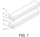
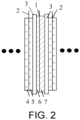
- the two opposite surfaces of the negative electrode current collector 1 are respectively provided with the first negative electrode film 7 and the second negative electrode film 6
- the two opposite surfaces of the positive electrode current collector 2 are respectively provided with the first positive electrode film 5 and the second positive electrode film 4
- the first positive electrode film 5 and the second negative electrode film 6 are adjacent via the separator 3
- the second positive electrode film 4 and the first negative electrode film 7 are adjacent via the separator 3.
- the first positive electrode active substance in the raw material mixture of the first positive electrode film was replaced with lithium iron phosphate (LiFePO 4 ), where the discharge gram capacity of LiFePO 4 at a current density of 0.1C was 157 mAh/g.
- LiFePO 4 lithium iron phosphate
- the degree of orientation OI of the first negative electrode film was 8, and the degree of orientation OI of the second negative electrode film was 20.
- Both the first positive electrode film and the second positive electrode film in the positive electrode plate were prepared by coating the raw material mixture A 1 of the first positive electrode film in Example 1.
- Both the first negative electrode film and the second negative electrode film of the negative electrode plate were prepared by coating the raw material mixture B 2 of the second negative electrode film in Example 1, where the degrees of orientation OI of both the first negative electrode film and the second negative electrode film were 18.
- Both the first positive electrode film and the second positive electrode film in the positive electrode plate were prepared by coating the raw material mixture A 2 of the second positive electrode film in Example 1.
- Both the first negative electrode film and the second negative electrode film of the negative electrode plate were prepared by coating the raw material mixture B 1 of the first negative electrode film in Example 1, where the degrees of orientation OI of both the first negative electrode film and the second negative electrode film were 8.
- the first negative electrode film was prepared by coating the raw material mixture B 2 of the second negative electrode film in Example 1; and the second negative electrode film was prepared by coating the raw material mixture B 1 of the first negative electrode film in Example 1, where the degree of orientation OI of the first negative electrode film was 18, and the degree of orientation OI of the second negative electrode film was 8.
- the first negative electrode film was prepared by coating the raw material mixture B 2 of the second negative electrode film in Example 1, and the degree of orientation OI of the first negative electrode film was 18.
- the degree of orientation OI of the second negative electrode film was 20.
- Both the first positive electrode film and the second positive electrode film in the positive electrode plate were prepared by coating the raw material mixture A 1 of the first positive electrode film in Example 1.
- the degree of orientation OI of the first negative electrode film was 18; and the degree of orientation OI of the second negative electrode film was 7.
- Both the first negative electrode film and the second negative electrode film in the negative electrode plate were prepared by coating the raw material mixture B 2 of the second negative electrode film in Example 1, where the degrees of orientation OI of both the first negative electrode film and the second negative electrode film were 18.
- Example 1 to Example 2 and Comparative Example 1 to Comparative Example 6 are shown in Table 1.
- Table 1 Thickness of first positive electrode film ( ⁇ m) Thickness of second positive electrode film ( ⁇ m) Thickness of first negative electrode film ( ⁇ m) Thickness of second negative electrode film ( ⁇ m)
- Example 1 91 47 52 54
- Example 2 76 47 52 54
- Comparative Example 1 91 91 52 52
- Comparative Example 5 91 91 52 55 Comparative Example 6 91 91 52 52
- Capacity retention rates of the batteries prepared from Example 1 to Example 2 and Comparative Example 1 to Comparative Example 6 were tested after 0 to 1000 cycles under the condition of a charging or discharging voltage of 1C at 45°C. The results are shown in Table 2.
- Table 2 Capacity retention rate Number of cycles Example 1 Example 2 Comparative Example 1 Comparative Example 2 Comparative Example 3 Comparative Example 4 Comparative Example 5 Comparative Example 6 0 100% 100% 100% 100% 100% 100% 100% 100% 100% 100 99.95% 99.20% 98.19% 98.54% 99.0% 99.1% 99.75% 99.65% 200 98.67% 98.66% 97.50% 96.09% 98.1% 98.3% 98.5% 98.32% 300 97.46% 97.32% 96.78% 94.40% 97.0% 97.1% 97.5% 97.01% 500 94.35% 95.04% 95.67% 92.01% 94.6% 94.8% 94.3% 93.75% 700 92.26% 92.83% 93.71% 89.09% 92.4% 92.6%
- the disclosure reasonably matches the positive electrode materials and the negative electrode materials.
- the batteries prepared from Example 1 and Example 2 have advantages of high energy density and good cycling performance. Specifically, the energy density can reach 246 wh/kg or more, and the capacity retention rate after 1000 cycles can be 90.32% or even more.
- Comparative Example 1 adopted the same first positive electrode film and second positive electrode film, both of which were phosphate positive electrodes, and adopted the same first negative electrode film and second negative electrode film, both of which were negative electrodes with high OI values. It can be learned that although it had a capacity retention rate comparable to that of Example 1, its energy density was lower than that of Example 1 and was only 193 wh/kg.
- Comparing Example 1 and Comparative Example 2 adopted the same first positive electrode film and second positive electrode film, both of which were 8-series high-nickel ternary positive electrodes, and adopted the same first negative electrode film and second negative electrode film, both of which were negative electrodes with low OI values. It can be learned that although it retained the high energy density characteristic of the positive electrode material, its capacity retention rate after 1000 cycles was only 85.22%, which was lower than that of Example 1.
Landscapes
- Chemical & Material Sciences (AREA)
- Chemical Kinetics & Catalysis (AREA)
- Electrochemistry (AREA)
- General Chemical & Material Sciences (AREA)
- Inorganic Chemistry (AREA)
- Engineering & Computer Science (AREA)
- Materials Engineering (AREA)
- Composite Materials (AREA)
- Crystallography & Structural Chemistry (AREA)
- Manufacturing & Machinery (AREA)
- Battery Electrode And Active Subsutance (AREA)
- Secondary Cells (AREA)
Abstract
Description
- The disclosure relates to a cell and an electronic device.
- In 2021, the sales of new energy vehicles in China exceeded 3.3 million units, and the annual total sales of the new energy market in China exceeded 5.5 million units in 2022, most of which adopted lithium-ion power batteries. Globally, there is a consensus on the rapid growth of new energy vehicles, and the development of lithium-ion batteries has entered a golden era.
- In recent years, lithium-ion batteries have undergone rapid development, and most performance indicators have basically been improved meanwhile. Currently, energy density, safety, and costs are the main issues of concern to major cell suppliers.
- However, the weight energy density of conventional lithium iron phosphate power cells is generally 160 to 190 Wh/kg. Having a similar structure and energy storage mechanism to lithium iron phosphate, lithium manganese iron phosphate has a theoretical capacity comparable to lithium iron phosphate and has a higher voltage platform and can thus provide higher energy density, but it is still difficult to exceed 200 Wh/kg. Although the energy density of ternary lithium-ion batteries is higher, their high price and thermal safety make consumers somewhat hesitant. Thus, the industry chooses to use phosphate positive electrode materials together with high energy density positive electrode materials such as ternary positive electrodes, lithium-rich manganese-based positive electrodes, etc.
- Common phosphate positive electrodes and ternary materials are used by mixing internally in a slurry. Since phosphate has poor conductivity, more conductive agent is required. Also, the specific surface area is large, so more binder is required. As a result, the proportion of the main material in the electrode plate is low, which affects the total energy density of the cell. At the same time, phosphate positive electrode materials with low ionic conductivity and electronic conductivity may adsorb on the surface of ternary materials, which affects the capacity performance of the ternary materials.
- Moreover, materials such as lithium iron phosphate, lithium manganese iron phosphate, ternary positive electrode materials, and lithium-rich manganese-based materials each have more matching negative electrode graphite materials. If a mixed positive electrode is used, it will pose new challenges to the selection of graphite.
- To address the difficulty in matching the positive electrode material and the negative electrode material in the secondary battery in the related art and its impact on the total energy density and capacity performance of the cell, the disclosure provides a cell and an electronic device. The positive electrode and the negative electrode in the cell of the disclosure are reasonably matched, which can maximize the performances of total energy density and capacity of the cell while taking safety into account.
- The disclosure addresses the above technical problems mainly by the following technical solutions.
- According to a first aspect, the disclosure provides a cell including a positive electrode plate and a negative electrode plate alternately arranged along a cell thickness direction, with a separator provided between the positive electrode plate and the negative electrode plate. The positive electrode plate includes a positive electrode current collector, a first positive electrode film, and a second positive electrode film, and the first positive electrode film and the second positive electrode film are respectively arranged on two opposite surfaces of the positive electrode current collector. The first positive electrode film includes a first positive electrode active substance that includes a phosphate material, the second positive electrode film includes a second positive electrode active substance that has a gram capacity greater than a gram capacity of the first positive electrode active substance. The negative electrode plate includes a negative electrode current collector, a first negative electrode film, and a second negative electrode film, and the first negative electrode film and the second negative electrode film are respectively arranged on two opposite surfaces of the negative electrode current collector. The first negative electrode film includes a first negative electrode active substance, the second negative electrode film includes a second negative electrode active substance, and OI2-OI>5 is satisfied, where OI2 is an OI value of the second negative electrode film, and OI1 is an OI value of the first negative electrode film.
- According to a second aspect, the disclosure further provides an electronic device including the cell described above.
- The positive progressive effects of the disclosure are as follows. The disclosure selects different positive electrode formulations for different negative electrode formulations to maximize matching in the mixing system and achieve a combination of high energy density, high safety, and low costs.
-
-
FIG. 1 is a schematic structure diagram of a cell prepared in Example 1 to Example 2 of the disclosure. (1: negative electrode current collector; 2: positive electrode current collector; 4: second positive electrode film; 5: first positive electrode film; 6: second negative electrode film; 7: first negative electrode film.) -
FIG. 2 is a simplified structure diagram of the cell prepared in Example 1 to Example 2 of the disclosure. (1: negative electrode current collector; 2: positive electrode current collector; 3: separator; 4: second positive electrode film; 5: first positive electrode film; 6: second negative electrode film; 7: first negative electrode film.) - In the following text, the disclosure will be described in more detail to better understand the disclosure. It should be understood that the words or terms used in this specification and the claims should not be interpreted as having the meanings defined in common dictionaries. It should be further understood that the words or terms should be interpreted as having meanings consistent with their meanings in the relevant technical context and the technical concept of the disclosure, based on the principle that the inventors may appropriately define the meanings of the words or terms to best interpret the disclosure.
- In the cell according to the first aspect of the disclosure:
- The two surfaces of the positive electrode respectively adopt a phosphate material and a high density active substance, which respectively correspond in a one-to-one manner to a high energy density film and a fast charging high kinetics film of the negative electrode. The positive and negative electrodes match each other to achieve a balance between energy density and fast charging performance.
- In the disclosure, the first positive electrode film is adjacent to the second negative electrode film via a separator, and the second positive electrode film is adjacent to the first negative electrode film via a separator.
- In the disclosure, as the first positive electrode active substance, the phosphate material may be a positive electrode phosphate material commonly used in this field, preferably lithium iron phosphate and/or lithium manganese iron phosphate. The use of the phosphate material can reduce the system cost and improve safety performance.
- Preferably, based on the mass of the first positive electrode film, the mass content of the phosphate material is 92% to 97%, for example, 94% or 95%.
- Preferably, the discharge gram capacity of the phosphate material at a current density of 0.1C is 160 mAh/g or below, more preferably 127 to 160 mAh/g, for example, 141 mAh/g or 157 mAh/g.
- In the disclosure, the second positive electrode active substance is a high energy density active substance commonly used in this field, and its use can enhance the energy density and low temperature cycling performance of the battery.
- Preferably, the second positive electrode active substance includes one or more of lithium manganate, lithium cobalt oxide, lithium nickelate, lithium nickel cobalt aluminum oxide, lithium nickel cobalt manganese oxide, and lithium-rich manganese-based materials.
- When the second positive electrode active substance includes lithium nickel cobalt aluminum oxide or lithium nickel cobalt manganese oxide, in the lithium nickel cobalt aluminum oxide or lithium nickel cobalt manganese oxide, based on the mass of the lithium nickel cobalt aluminum oxide or lithium nickel cobalt manganese oxide, the mass content of Ni is 60% or more.
- Preferably, based on the mass of the second positive electrode film, the content of the second positive electrode active substance is 94% to 98%, for example, 96%.
- Preferably, the discharge gram capacity of the second positive electrode active substance at a current density of 0.1C is 180 mAh/g or more, more preferably 180 to 210 mAh/g, for example, 198 mAh/g.
- In some preferred embodiments, the content of the second positive electrode active substance is greater than the content of the first positive electrode active substance.
- In some preferred embodiments, the first positive electrode active substance is lithium manganese iron phosphate, and the second positive electrode active substance is lithium nickel cobalt manganese oxide.
- The lithium manganese iron phosphate is preferably LiMn0.6Fe0.4PO4, and the lithium nickel cobalt manganese oxide is preferably LiNi0.8Co0.1Mn0.1O2.
- In some preferred embodiments, the first positive electrode active substance is lithium iron phosphate, and the second positive electrode active substance is lithium nickel cobalt manganese oxide.
- The lithium iron phosphate is preferably LiFePO4, and the lithium nickel cobalt manganese oxide is preferably LiNi0.8Co0.1Mn0.1O2.
- In the disclosure, the thickness ratio of the first positive electrode film to the second positive electrode film is preferably (1.1 to 2.5), for example, 1.98: 1 or 1.63: 1.
- In the disclosure, the thickness of the first positive electrode film may be 50 to 120 µm, preferably 60 to 100 µm, for example, 76 µm or 91 µm.
- In the disclosure, the thickness of the second positive electrode film may be 30 to 90 µm, preferably 40 to 70 µm, for example, 47 µm.
- In the disclosure, positive electrode active substances of different capacities are selected, which require negative electrode materials with matching capacities. When an appropriate thickness ratio is selected, it is possible to control the thickness difference between the front and back surfaces of the negative electrode to be small, which is beneficial for the processing of the negative electrode.
- The thickness described in the disclosure is calculated according to the following method.
- Let the thickness of the first positive electrode film be hi, the specific discharge capacity of the first positive electrode film be x1, and the specific discharge capacity of the second negative electrode film be x2; the proportion of the first positive electrode active substance be y1, the proportion of the second negative electrode active substance be y2, the compacted density of the first positive electrode film after rolling be zi, and the compacted density of the second negative electrode film after rolling be z2; and N/P be a1. Then, the thickness h2 of the second negative electrode film is

- Let the thickness of the second positive electrode film be hs, the specific discharge capacity of the second positive electrode film be x3, and the specific discharge capacity of the first negative electrode film be x4; the proportion of the second positive electrode active substance be y3, the proportion of the first negative electrode active substance be y4, the compacted density of the second positive electrode film after rolling be z3, and the compacted density of the first electrode film after rolling be z4; and N/P be a2. Then the thickness h4 of the first negative electrode film is

- N/P may be 1.02 to 1.14, and a1 ≥ a2. The N/P, which stands for negative/positive, is "capacity of negative electrode per unit area/capacity of positive electrode per unit area", and is generally a ratio of charging capacity.
- z3 > z1, and z3-z1 > 0.4 g/cm3. Since it is required to design a constant pressure and roll gap width in the rolling process of the positive electrode film, the compacted density z1 of the first positive electrode film and the compacted density z3 of the second positive electrode film are different.
- In some specific embodiments, the thickness of the first positive electrode film is 50 to 120 µm; the compacted density of the first positive electrode film is 2.2 to 2.6 g/cm3; the thickness of the second positive electrode film is 30 to 90 µm; and the compacted density of the second positive electrode film is 3.3 to 3.7 g/cm3.
- In the disclosure, the first positive electrode film generally further includes a first positive electrode conductive agent, a first positive electrode binder, and a first positive electrode dispersant; and the second positive electrode film generally further includes a second positive electrode conductive agent, a second positive electrode binder, and a second positive electrode dispersant.
- There are no specific restrictions on the first positive electrode conductive agent and the second positive electrode conductive agent, as long as they are conductive and do not cause chemical changes in the battery. Specific examples include: graphite, such as natural graphite or artificial graphite; carbon-based materials, such as carbon black, acetylene black, Ketjen black, channel black, furnace black, lamp black, thermal carbon black, and carbon fibers; metal powders or metal fibers, such as copper, nickel, aluminum, and silver; conductive whiskers, such as zinc oxide whiskers and potassium titanate whiskers; conductive metal oxides, such as titanium dioxide; or conductive polymers, such as polyphenylene derivatives, etc.
- In the first positive electrode film, the content of the first conductive agent is preferably 1% to 3%, for example, 2%, where the percentage is the percentage of the mass of the first conductive agent in the mass of the first positive electrode film.
- In the second positive electrode film, the mass ratio of the second conductive agent is preferably 0.5% to 2%, for example, 1.5%, where the percentage is the percentage of the mass of the second conductive agent in the mass of the second positive electrode film.
- The first positive electrode binder and the second positive electrode binder serve to enhance the binding between the positive electrode active substance particles and the adhesion between the positive electrode active substance and the positive electrode current collector. There are no specific restrictions on their types, and specific examples of the binders may include polyvinylidene fluoride (PVDF), polyvinylidene fluoride-co-hexafluoropropylene (PVDF-co-HFP), polyvinyl alcohol, polyacrylonitrile, carboxymethyl cellulose (CMC), starch, hydroxypropyl cellulose, regenerated cellulose, polyvinylpyrrolidone, tetrafluoroethylene, polyethylene, polypropylene, ethylene-propylene-diene monomer (EPDM), sulfonated EPDM, styrene-butadiene rubber (SBR), fluororubber, or various copolymers thereof, and any one or a mixture of two or more of the above may be used.
- In the first positive electrode film, the content of the first binder is preferably 1.5% to 4%, for example, 3.5%, where the percentage is the percentage of the mass of the first binder in the mass of the first positive electrode film. An increase in the proportions of the conductive agent and the binder in the first positive electrode film can enhance the electrochemical performance of the phosphate material.
- In the second positive electrode film, the mass ratio of the second binder is preferably 0.5% to 2%, where the percentage is the percentage of the mass of the second binder in the mass of the second positive electrode film.
- Preferably, the content of the second positive electrode binder is lower than the content of the first positive electrode binder.
- The first dispersant and the second dispersant may be substances commonly used in this field to improve dispersion uniformity of the active substances.
- In the first positive electrode film, the content of the first dispersant may be 0 to 1%, where the percentage is the percentage of the mass of the first dispersant in the mass of the first positive electrode film.
- In the second positive electrode film, the content of the second dispersant may be 0 to 1%, where the percentage is the percentage of the mass of the second dispersant in the mass of the second positive electrode film.
- In the disclosure, the method for preparing the positive electrode plate includes the following steps: coating the raw material mixture of the first positive electrode film and the raw material mixture of the second positive electrode film respectively on two surfaces of the positive electrode current collector to obtain the positive electrode plate.
- In the disclosure, the surface density generally refers to the mass of the raw material mixture coated per unit area, and refers to one surface.
- In some specific embodiments of the disclosure, the surface densities of the first positive electrode film and the second positive electrode film may be 15 to 32 mg/cm2, preferably 20 to 25 mg/cm2, for example, 22 mg/cm2.
- In some preferred embodiments, the surface density of the second positive electrode film is less than the surface density of the first positive electrode film.
- In some preferred embodiments, the surface density of the raw material composition of the second positive electrode film during coating is 60% to 95% of the surface density of the raw material composition of the first positive electrode film during coating.
- In the disclosure, the OI value refers to the degree of orientation, which may be calculated based on data measured by XRD. The OI value is a ratio of the peak area of the 004 characteristic peak in the X-ray diffraction spectrum of the negative electrode film to the peak area of the 110 characteristic peak in the X-ray diffraction spectrum of the negative electrode film.
- In the disclosure, OI1=C004/C110, where C004 is the peak area of the 004 characteristic diffraction peak in the X-ray diffraction spectrum of the first negative electrode film; and C110 is the peak area of the 110 characteristic diffraction peak in the X-ray diffraction spectrum of the first negative electrode film.
- OI2=C'004/C'110, where C'004 is the peak area of the 004 characteristic diffraction peak in the X-ray diffraction spectrum of the second negative electrode film; and C'110 is the peak area of the 110 characteristic diffraction peak in the X-ray diffraction spectrum of the second negative electrode film.
- In the disclosure, XRD is measured with Bruker D8A25 X-ray diffractometer.
- The magnitude of the OI value of the negative electrode film may reflect the degree of stacking orientation of the negative electrode active material particles in the negative electrode film, which directly affects the expansion of the negative electrode plate in the cycling process. In the charging process, lithium ions are de-intercalated from the positive electrode active substance and intercalated in the negative electrode active substance, so the OI value of the negative electrode film has a great impact on the charging speed and cycle life of the lithium-ion battery.
- When the difference between OI2 and OI1 is greater than 5, the high energy and high kinetics characteristics of the different active substances on two surfaces of the negative electrode plate can be fully utilized. Specifically, the high energy active substance has advantages of high gram capacity and high degree of orientation and can contribute to higher energy density. In the related art, active substances with high OI and low OI are mixed and used together, but the mixture of low OI value with high OI generally fails to create excellent rate capability and high kinetics performance. In the disclosure, active substances with high OI and low OI values are respectively coated on two opposite surfaces of the negative electrode current collector, which can balance the combination of high kinetics and energy density.
- In some specific embodiments, the OI value OI1 of the first negative electrode film is 2 to 15, preferably 4 to 10.
- In some specific embodiments, the OI value OI2 in the second negative electrode film is 15 to 50, preferably 15 to 40.
- In some preferred embodiments, the OI2-OI1 is 5 to 15, for example, 12 or 14.
- In the disclosure, the first negative electrode active substance and the second negative electrode active substance may each independently include one or two of graphite and silicon materials. The graphite includes natural graphite or artificial graphite; and the silicon materials include at least one of silicon-carbon material or carbon-silicon-oxygen material.
- It can be understood that the silicon-carbon material refers to a material that contains both silicon element and carbon element. Exemplarily, the silicon-carbon material has a structure in which silicon nanocrystal particles are filled in pores of a carbon skeleton. It can be understood that the silicon-oxygen-carbon material refers to a material that contains silicon element, oxygen element, and carbon element at the same time. Exemplarily, the silicon-oxygen-carbon material has as structure in which silicon nanocrystal particles are dispersed in a silicon dioxide matrix to form a composite, and elemental carbon is wrapped on the outer surface of the composite.
- In the disclosure, based on the mass of the first negative electrode film, the mass content of the first negative electrode active substance is 93 to 98%, for example, 96%.
- In the disclosure, based on the mass of the first negative electrode film, the first negative electrode film may further include 0.2 to 1.5% of a first negative electrode conductive agent, 1 to 3% of a first negative electrode binder, and 0.01 to 1.5% of a first negative electrode dispersant.
- In the disclosure, based on the mass of the second negative electrode film, the mass content of the second negative electrode active substance is preferably 95 to 98.5%, for example, 95%.
- In some specific embodiments, the types of the first negative electrode active substance and the second negative electrode active substance are the same as each other, and the mass content of the first negative electrode active substance is lower than the mass content of the second negative electrode active substance. When the mass contents of the first negative electrode active substance and the second negative electrode active substance satisfy the above conditions, the capacity retention rate of the battery can be effectively improved.
- In the disclosure, based on the mass of the second negative electrode film, the second negative electrode film may further include 0.2 to 1.5% of a second negative electrode conductive agent, 0.5 to 2% of a second negative electrode binder, and 0.01 to 1.5% of a second negative electrode dispersant.
- The first negative electrode conductive agent and the second negative electrode conductive agent are reagents used to ensure that the electrode has good charge and discharge performance. They may be selected from any of graphite materials such as natural graphite and artificial graphite, carbon black materials such as carbon black, acetylene black, Ketjen black, channel black, furnace black, lamp black, and thermal carbon black, conductive fibers such as carbon fibers and metal fibers, metal powders such as fluorocarbon powder, aluminum powder, and nickel powder, conductive whiskers such as zinc oxide, potassium titanate, and conductive metal oxides such as titanium dioxide, or polyphenylene derivatives.
- The first negative electrode binder and the second negative electrode binder are components that contribute to binding between the active substance and the conductive agent and contribute to combination of the active substance with the current collector. They may generally be selected from polyvinylidene difluoride, polyvinyl alcohol, carboxymethyl cellulose (CMC), starch, hydroxypropyl cellulose, regenerated cellulose, polyvinylpyrrolidone, polyacrylic acid (PAA), tetrafluoroethylene, polyethylene, polypropylene, ethylene-propylene-diene terpolymer (EPDM), sulfonated EPDM, styrene-butadiene rubber (SBR), fluororubber, and various copolymers.
- In the disclosure, the thickness of the first negative electrode film and the thickness of the second negative electrode film may be the same as or different from each other.
- In some specific embodiments, the compacted density of the second negative electrode film is greater than that of the first negative electrode film.
- In some specific embodiments, the gram capacity of the second negative electrode film is greater than that of the first negative electrode film.
- In some specific embodiments, the thickness of the second negative electrode film is slightly greater than that of the first negative electrode film.
- In the disclosure, the thickness of the first negative electrode film may be 50 to 100 µm, preferably 50 to 60µm, for example, 52µm.
- In the disclosure, the thickness of the second negative electrode film may be 50 to 100 µm, preferably 50 to 60µm, for example, 54µm.
- In some specific embodiments, the first positive electrode active substance is lithium manganese iron phosphate, the second positive electrode active substance is lithium nickel cobalt manganese oxide, the first negative electrode active substance is artificial graphite, and the second negative electrode active substance is artificial graphite, where OI2-OI1 is 10.
- In some more specific embodiments, the first positive electrode active substance is lithium manganese iron phosphate, the thickness of the first positive electrode film is 91 µm, the second positive electrode active substance is lithium nickel cobalt manganese oxide, and the thickness of the second positive electrode film is 47 µm; the first negative electrode active substance is artificial graphite, the thickness of the first negative electrode film is 52 µm, the second negative electrode active substance is artificial graphite, the thickness of the second negative electrode film is 54 µm, and OI2-OI1 is 10.
- In some specific embodiments, the first positive electrode active substance is lithium iron phosphate, the second positive electrode active substance is lithium nickel cobalt manganese oxide, the first negative electrode active substance is artificial graphite, and the second negative electrode active substance is artificial graphite, where OI2-OI1 is 12.
- In some more specific embodiments, the first positive electrode active substance is lithium iron phosphate, the thickness of the first positive electrode film is 76 µm, the second positive electrode active substance is lithium nickel cobalt manganese oxide, and the thickness of the second positive electrode film is 47 µm; the first negative electrode active substance is artificial graphite, the thickness of the first negative electrode film is 52 µm, the second negative electrode active substance is artificial graphite, the thickness of the second negative electrode film is 54 µm, and OI2-OI1 is 12.
- In some specific embodiments of the disclosure, the surface densities of the first negative electrode film and the second negative electrode film may be 7 to 20 mg/cm2, preferably 8 to 12 mg/cm2, for example, 10 mg/cm2.
- In the disclosure, the method for preparing the negative electrode plate includes the following steps: coating the raw material mixture of the first negative electrode film and the raw material mixture of the second negative electrode film respectively on the two opposite surfaces of the negative electrode current collector to obtain the negative electrode plate.
- In the disclosure, the method for preparing the cell may adopt conventional methods in this field, and generally include the following steps: after rolling and slitting the positive electrode plate and the negative electrode plate, successively stacking the positive electrode plate, the separator, and the negative electrode plate by cutting, stacking, or winding processes to form a cell.
- The electronic device according to the third aspect of the disclosure includes the cell described above.
- Exemplarily, the electronic device of the disclosure may be, but is not limited to, a mobile device (e.g., a mobile phone, a tablet computer, a laptop, a camcorder, a portable printer/copier, etc.), an electric vehicle (e.g., a pure electric car, a hybrid electric car, a plug-in hybrid electric car, an electric bicycle, an electric scooter, an electric golf cart, an electric truck, etc.), an electric train, a ship and a satellite, an energy storage system, a backup power supply, etc.
- Based on the common knowledge in this field, the above preferred conditions may be combined in any manner to obtain the better examples of the disclosure. The disclosure will be further illustrated based on the following examples, but the disclosure is not thus limited to the scope of the described examples. Any experimental methods in the following examples for which specific conditions are not described may be selected according to conventional methods and conditions or according to product instruction manuals.
- Preparation of raw material mixture A1 of first positive electrode film: A mixture of lithium manganese iron phosphate (LiMn0.6Fe0.4PO4), a conductive agent SP, and a binder PVDF with a mass ratio of 95.5:2:2.5 was fully stirred in a stirrer, and then a solvent N-methylpyrrolidone was added at a solid content of 55% and stirred and uniformly mixed to prepare a first positive electrode slurry A1. The discharge gram capacity of LiMn0.6Fe0.4PO4 at a current density of 0.1C was 141 mAh/g.
- Preparation of raw material mixture A2 of second positive electrode film: A mixture of LiNi0.8Co0.1Mn0.1O2, a conductive agent SP, and a binder PVDF with a mass ratio of 97:1.5:1.5 was fully stirred in a stirrer, and then a solvent N-methylpyrrolidone was added at a solid content of 60% and stirred and uniformly mixed to prepare a second positive electrode slurry A2. The discharge gram capacity of LiNi0.8Co0.1Mn0.1O2 at a current density of 0.1C was 198 mAh/g.
- The raw material mixture A1 of the first positive electrode film and the raw material mixture A2 of the second positive electrode film were uniformly coated on the current collector at a surface density of 22 mg/cm2, and then treated with a coating drying machine to prepare a positive electrode plate of a specified size.
- Preparation of raw material mixture B1 of the first negative electrode film: A mixture of artificial graphite, a conductive agent SP, a binder SBR+PAA, and a dispersant CMC with a mass ratio of 96:1:2:1 was fully stirred in a stirrer, and then a solvent N-methylpyrrolidone or deionized water was added at a solid content of 58% and stirred and uniformly mixed to prepare a first negative electrode slurry B1.
- Preparation of raw material mixture B2 of second negative electrode film: A mixture of artificial graphite, a conductive agent SP, a binder SBR+PAA, and a dispersant CMC with a mass ratio of 95:1.5:2.5:1 was fully stirred in a stirrer, and then a solvent N-methylpyrrolidone or deionized water was added at a solid content of 56% and stirred and uniformly mixed to prepare a second negative electrode slurry B2.
- The raw material mixture B1 of the first negative electrode film and the raw material mixture B2 of the second negative electrode film were uniformly coated on two surfaces of the current collector at a surface density of 10 mg/cm2 to prepare a first negative electrode film and a second negative electrode film, which was then treated with a coating drying machine to prepare a negative electrode plate of a specified size. The degree of orientation OI1 of the first negative electrode film was 8, and the degree of orientation OI2 of the second negative electrode film was 18.
- The organic solvent was a mixture of ethylene carbonate (EC), ethyl methyl carbonate (EMC), and diethyl carbonate (DEC), where the volume ratio of EC, EMC, and DEC was 20:20:60. In an argon atmosphere glove box with a moisture content of <10ppm, a thoroughly dried lithium salt (LiPF6) was dissolved in the organic solvent described above, and after mixing uniformly, an electrolytic solution was obtained, where the concentration of LiPF6 was 1 mol/L.
- (4) Preparing separator: A polypropylene separator with a thickness of 12 µm was selected.
- (5) Assembly of cell and lithium-ion battery: The positive electrode plate, the negative electrode plate, and the separator were subjected to rolling-slitting and cutting-stacking to prepare a cell. The bare cell JR was then placed in a shell, was thoroughly baked such that the moisture content was 450 ppm or below, and then was subj ected to processes including electrolyte injection, battery formation, sealing, and inspection to prepare a square hard-shell lithium-ion battery. The structure of the assembled cell is shown in
FIG. 1 andFIG. 2 , in which the two opposite surfaces of the negative electrodecurrent collector 1 are respectively provided with the firstnegative electrode film 7 and the secondnegative electrode film 6, the two opposite surfaces of the positive electrodecurrent collector 2 are respectively provided with the firstpositive electrode film 5 and the secondpositive electrode film 4, the firstpositive electrode film 5 and the secondnegative electrode film 6 are adjacent via the separator 3, and the secondpositive electrode film 4 and the firstnegative electrode film 7 are adjacent via the separator 3. - The first positive electrode active substance in the raw material mixture of the first positive electrode film was replaced with lithium iron phosphate (LiFePO4), where the discharge gram capacity of LiFePO4 at a current density of 0.1C was 157 mAh/g.
- The degree of orientation OI of the first negative electrode film was 8, and the degree of orientation OI of the second negative electrode film was 20.
- The other formulation components and preparation methods were the same as in Example 1.
- Both the first positive electrode film and the second positive electrode film in the positive electrode plate were prepared by coating the raw material mixture A1 of the first positive electrode film in Example 1.
- Both the first negative electrode film and the second negative electrode film of the negative electrode plate were prepared by coating the raw material mixture B2 of the second negative electrode film in Example 1, where the degrees of orientation OI of both the first negative electrode film and the second negative electrode film were 18.
- The other formulation components and preparation methods were the same as in Example 1.
- Both the first positive electrode film and the second positive electrode film in the positive electrode plate were prepared by coating the raw material mixture A2 of the second positive electrode film in Example 1.
- Both the first negative electrode film and the second negative electrode film of the negative electrode plate were prepared by coating the raw material mixture B1 of the first negative electrode film in Example 1, where the degrees of orientation OI of both the first negative electrode film and the second negative electrode film were 8.
- The other formulation components and preparation methods were the same as in Example 1.
- The first negative electrode film was prepared by coating the raw material mixture B2 of the second negative electrode film in Example 1; and the second negative electrode film was prepared by coating the raw material mixture B1 of the first negative electrode film in Example 1, where the degree of orientation OI of the first negative electrode film was 18, and the degree of orientation OI of the second negative electrode film was 8.
- The other formulation components and preparation methods were the same as in Example 1.
- The first negative electrode film was prepared by coating the raw material mixture B2 of the second negative electrode film in Example 1, and the degree of orientation OI of the first negative electrode film was 18.
- The degree of orientation OI of the second negative electrode film was 20.
- The other formulation components and preparation methods were the same as in Example 1.
- Both the first positive electrode film and the second positive electrode film in the positive electrode plate were prepared by coating the raw material mixture A1 of the first positive electrode film in Example 1.
- The degree of orientation OI of the first negative electrode film was 18; and the degree of orientation OI of the second negative electrode film was 7.
- The other formulation components and preparation methods were the same as in Example 1.
- Both the first negative electrode film and the second negative electrode film in the negative electrode plate were prepared by coating the raw material mixture B2 of the second negative electrode film in Example 1, where the degrees of orientation OI of both the first negative electrode film and the second negative electrode film were 18.
- The rest was the same as in Example 1.
- The film thicknesses of Example 1 to Example 2 and Comparative Example 1 to Comparative Example 6 are shown in Table 1.
Table 1 Thickness of first positive electrode film (µm) Thickness of second positive electrode film (µm) Thickness of first negative electrode film (µm) Thickness of second negative electrode film (µm) Example 1 91 47 52 54 Example 2 76 47 52 54 Comparative Example 1 91 91 52 52 Comparative Example 2 47 47 54 54 Comparative Example 3 91 47 54 52 Comparative Example 4 91 47 52 52 Comparative Example 5 91 91 52 55 Comparative Example 6 91 91 52 52 - Capacity retention rates of the batteries prepared from Example 1 to Example 2 and Comparative Example 1 to Comparative Example 6 were tested after 0 to 1000 cycles under the condition of a charging or discharging voltage of 1C at 45°C. The results are shown in Table 2.
Table 2 Capacity retention rate Number of cycles Example 1 Example 2 Comparative Example 1 Comparative Example 2 Comparative Example 3 Comparative Example 4 Comparative Example 5 Comparative Example 6 0 100% 100% 100% 100% 100% 100% 100% 100% 100 99.95% 99.20% 98.19% 98.54% 99.0% 99.1% 99.75% 99.65% 200 98.67% 98.66% 97.50% 96.09% 98.1% 98.3% 98.5% 98.32% 300 97.46% 97.32% 96.78% 94.40% 97.0% 97.1% 97.5% 97.01% 500 94.35% 95.04% 95.67% 92.01% 94.6% 94.8% 94.3% 93.75% 700 92.26% 92.83% 93.71% 89.09% 92.4% 92.6% 91.9% 91.01% 1000 90.32% 90.57% 91.85% 85.22% 89.1% 90.1% 89.5% 87.62% Table 3 Example 1 Example 2 Comparative Example 1 Comparative Example 2 Comparative Example 3 Comparative Example 4 Comparative Example 5 Comparative Example 6 Energy density (wh/kg) 246 239 193 273 243 248 191 244 - As can be learned from Table 2 and Table 3, the disclosure reasonably matches the positive electrode materials and the negative electrode materials. Under these matching conditions, the batteries prepared from Example 1 and Example 2 have advantages of high energy density and good cycling performance. Specifically, the energy density can reach 246 wh/kg or more, and the capacity retention rate after 1000 cycles can be 90.32% or even more.
- Comparing Example 1 and Comparative Example 1, Comparative Example 1 adopted the same first positive electrode film and second positive electrode film, both of which were phosphate positive electrodes, and adopted the same first negative electrode film and second negative electrode film, both of which were negative electrodes with high OI values. It can be learned that although it had a capacity retention rate comparable to that of Example 1, its energy density was lower than that of Example 1 and was only 193 wh/kg.
- Comparing Example 1 and Comparative Example 2, Comparative Example 2 adopted the same first positive electrode film and second positive electrode film, both of which were 8-series high-nickel ternary positive electrodes, and adopted the same first negative electrode film and second negative electrode film, both of which were negative electrodes with low OI values. It can be learned that although it retained the high energy density characteristic of the positive electrode material, its capacity retention rate after 1000 cycles was only 85.22%, which was lower than that of Example 1.
- Comparing Example 1 and Comparative Example 3, in Comparative Example 3, the first negative electrode film (low OI value) was adjacent to the first positive electrode film, and the second negative electrode film (high OI value) was adjacent to the second positive electrode film. Although its energy density was comparable to that of Example 1, its cycling stability was lower than that of Example 1.
- Comparing Example 1 and Comparative Example 4, in Comparative Example 4, both the first negative electrode film and the second negative electrode film adopted negative electrode materials with high OI values, and the difference of OI2-OI1 was 2. As a result, its capacity retention rate after 1000 cycles was 90.1%, and the energy density was 248 wh/kg.
- Comparing Example 1 and Comparative Example 5, in Comparative Example 5, both the first positive electrode film and the second positive electrode film adopted the same phosphate positive electrode material. Its energy density was only 191 wh/kg, and its capacity retention rate after 1000 cycles was only 89.5%, both of which were lower than those of Example 1.
- Comparing Example 1 and Comparative Example 6, in Comparative Example 6, both the first negative electrode film and the second negative electrode film adopted the same negative electrode material with a high OI value, and the difference of OI2-OI1 was 0. Although its energy density was comparable to that of Example 1, its cycling stability was lower than that of Example 1, and the capacity retention rate after 1000 cycles was only 87.62%.
- As can be learned from the above comparisons, it was the special matching relationship between the positive and negative electrode materials in the disclosure that created the excellent energy density and cycling performance.
- After the batteries prepared from Example 1 to Example 2, Comparative Example 1, Comparative Example 2, and Comparative Example 6 were cycled 1000 times under the condition of a charging or discharging voltage of 1C at 45°C, the negative electrode of the cell was dissembled and subjected to ICP test analysis. The results are shown in Table 4.
Table 4 Ni Co Fe Mn First negative electrode film of Example 1 / / 190 ppm 540 ppm Second negative electrode film of Example 1 240 ppm 90 ppm / 40 ppm First negative electrode film of Example 2 / / / 30 ppm Second negative electrode film of Example 2 630 ppm 280 ppm / 110 ppm Negative electrode film of Comparative Example 1 / / 230 ppm 770 ppm Negative electrode film of Comparative Example 2 430 ppm 120 ppm / 50 ppm First negative electrode film of Comparative Example 6 / / 220 ppm 660 ppm Second negative electrode film of Comparative Example 6 580 ppm 190 ppm / 80 ppm - As can be learned from Table 4, the ICP test element distributions after cycling of the cells prepared from Example 1, Example 2, Comparative Example 1, Comparative Example 2, and Comparative Example 6 were also different. After 1000 cycles, Co and Ni were present on the negative electrode plate, which suggests that the material used in its positive electrode included nickel, cobalt and manganese.
Claims (10)
- A cell, comprising a positive electrode plate and a negative electrode plate alternately arranged along a cell thickness direction, with a separator (3) provided between the positive electrode plate and the negative electrode plate, whereinthe positive electrode plate comprises a positive electrode current collector (2), a first positive electrode film (5), and a second positive electrode film (4), and the first positive electrode film (5) and the second positive electrode film (5) are respectively arranged on two opposite surfaces of the positive electrode current collector (2), wherein the first positive electrode film (5) comprises a first positive electrode active substance that comprises a phosphate material, the second positive electrode film (4) comprises a second positive electrode active substance that has a gram capacity greater than a gram capacity of the first positive electrode active substance, andthe negative electrode plate comprises a negative electrode current collector (1), a first negative electrode film (7), and a second negative electrode film (6), and the first negative electrode film (7) and the second negative electrode film (6) are respectively arranged on two opposite surfaces of the negative electrode current collector (1), wherein the first negative electrode film (7) comprises a first negative electrode active substance, the second negative electrode film (6) comprises a second negative electrode active substance, and OI2-OI1>5 is satisfied, wherein OI2 is an OI value of the second negative electrode film (6), and OI1 is an OI value of the first negative electrode film (7).
- The cell according to claim 1, wherein the first positive electrode film (5) is adjacent to the second negative electrode film (6) via the separator (3), and the second positive electrode film (4) is adjacent to the first negative electrode film (7) via the separator (3).
- The cell according to claim 1, wherein a thickness ratio of the first positive electrode film (5) to the second positive electrode film (4) is (1.1 to 2.5): 1.
- The cell according to claim 1, wherein the first positive electrode active substance and the second positive electrode active substance satisfy one or more of conditions a to d below:a. the phosphate material is lithium iron phosphate and/or lithium manganese iron phosphate;b. the second positive electrode active substance comprises one or more of lithium manganate, lithium cobalt oxide, lithium nickelate, lithium nickel cobalt aluminum oxide, lithium nickel cobalt manganese oxide, and lithium-rich manganese-based materials;c. a discharge gram capacity of the first positive electrode active substance at a current density of 0.1 C is 127 to 160 mAh/g; andd. a discharge gram capacity of the second positive electrode active substance at a current density of 0.1C is 180 to 210 mAh/g.
- The cell according to claim 1, wherein the first positive electrode active substance and the second positive electrode active substance satisfy one or more of conditions e to g below:e. based on a mass of the first positive electrode film, a mass content of the first positive electrode active substance is 92% to 97%;f. based on a mass of the second positive electrode film, a mass content of the second positive electrode active substance is 94 to 98%; andg. the mass content of the second positive electrode active substance is greater than the mass content of the first positive electrode active substance.
- The cell according to claim 1, wherein the first negative electrode film (7) and the second negative electrode film (6) satisfy one or more of conditions a to c below:a. the OI value OI1 in the first negative electrode film (7) is 2 to 15;b. the OI value OI2 in the second negative electrode film (6) is 15 to 50; andc. the OI2-OI1 is 5 to 15.
- The cell according to claim 1, wherein the first negative electrode active substance and the second negative electrode active substance each independently comprise one or both of graphite and silicon materials.
- The cell according to claim 1, wherein a thickness of the first negative electrode film (7) and a thickness of the second negative electrode film (6) satisfy at least one of conditions below:a. the thickness of the first negative electrode film (7) and the thickness of the second negative electrode film (6) are the same as or different from each other; andb. the thicknesses of the first negative electrode film (7) and the second negative electrode film (6) are 50 to100 µm.
- The cell according to claim 1, wherein, based on a mass of the first negative electrode film (7), a mass content of the first negative electrode active substance is 93 to 98%, and
based on a mass of the second negative electrode film (6), a mass content of the second negative electrode active substance is 95 to 98.5%. - An electronic device comprising the cell according to any one of claims 1 to 9.
Applications Claiming Priority (1)
| Application Number | Priority Date | Filing Date | Title |
|---|---|---|---|
| CN202310407390.3A CN118867102A (en) | 2023-04-14 | 2023-04-14 | Battery cells and electronic devices |
Publications (2)
| Publication Number | Publication Date |
|---|---|
| EP4447142A1 true EP4447142A1 (en) | 2024-10-16 |
| EP4447142B1 EP4447142B1 (en) | 2025-10-15 |
Family
ID=89223725
Family Applications (1)
| Application Number | Title | Priority Date | Filing Date |
|---|---|---|---|
| EP23217653.7A Active EP4447142B1 (en) | 2023-04-14 | 2023-12-18 | Cell and electronic device |
Country Status (5)
| Country | Link |
|---|---|
| US (1) | US20240347725A1 (en) |
| EP (1) | EP4447142B1 (en) |
| JP (1) | JP7774028B2 (en) |
| CN (1) | CN118867102A (en) |
| ES (1) | ES3050087T3 (en) |
Families Citing this family (1)
| Publication number | Priority date | Publication date | Assignee | Title |
|---|---|---|---|---|
| CN119674265A (en) * | 2024-12-10 | 2025-03-21 | 广汽埃安新能源汽车股份有限公司 | A laminated battery cell, a battery and an electrical device |
Citations (3)
| Publication number | Priority date | Publication date | Assignee | Title |
|---|---|---|---|---|
| US20210336244A1 (en) * | 2019-12-06 | 2021-10-28 | Contemporary Amperex Technology Co., Limited | Secondary battery and apparatus including the secondary battery |
| WO2022012477A1 (en) * | 2020-07-16 | 2022-01-20 | 珠海冠宇电池股份有限公司 | Silicon-doped negative electrode plate and lithium-ion battery comprising same |
| US20230098119A1 (en) * | 2021-09-08 | 2023-03-30 | Contemporary Amperex Technology Co., Limited | Negative electrode plate, secondary battery, battery pack, battery module, and electrical device |
Family Cites Families (3)
| Publication number | Priority date | Publication date | Assignee | Title |
|---|---|---|---|---|
| KR20210039599A (en) * | 2019-10-02 | 2021-04-12 | 주식회사 엘지화학 | Anode having double layers and secondary battery comprising the same |
| CN216213552U (en) * | 2021-10-12 | 2022-04-05 | 厦门海辰新能源科技有限公司 | Pole piece and pole piece assembly |
| JP7483910B2 (en) * | 2021-10-13 | 2024-05-15 | 寧徳時代新能源科技股▲分▼有限公司 | Electrode assembly, secondary battery, battery module, battery pack, and power consuming device |
-
2023
- 2023-04-14 CN CN202310407390.3A patent/CN118867102A/en active Pending
- 2023-12-13 US US18/539,150 patent/US20240347725A1/en active Pending
- 2023-12-14 JP JP2023210709A patent/JP7774028B2/en active Active
- 2023-12-18 ES ES23217653T patent/ES3050087T3/en active Active
- 2023-12-18 EP EP23217653.7A patent/EP4447142B1/en active Active
Patent Citations (4)
| Publication number | Priority date | Publication date | Assignee | Title |
|---|---|---|---|---|
| US20210336244A1 (en) * | 2019-12-06 | 2021-10-28 | Contemporary Amperex Technology Co., Limited | Secondary battery and apparatus including the secondary battery |
| WO2022012477A1 (en) * | 2020-07-16 | 2022-01-20 | 珠海冠宇电池股份有限公司 | Silicon-doped negative electrode plate and lithium-ion battery comprising same |
| US20230123455A1 (en) * | 2020-07-16 | 2023-04-20 | Zhuhai Cosmx Battery Co., Ltd. | Negative electrode plate and lithium-ion battery |
| US20230098119A1 (en) * | 2021-09-08 | 2023-03-30 | Contemporary Amperex Technology Co., Limited | Negative electrode plate, secondary battery, battery pack, battery module, and electrical device |
Also Published As
| Publication number | Publication date |
|---|---|
| CN118867102A (en) | 2024-10-29 |
| JP2024152579A (en) | 2024-10-25 |
| JP7774028B2 (en) | 2025-11-20 |
| US20240347725A1 (en) | 2024-10-17 |
| ES3050087T3 (en) | 2025-12-19 |
| EP4447142B1 (en) | 2025-10-15 |
Similar Documents
| Publication | Publication Date | Title |
|---|---|---|
| JP7254875B2 (en) | Positive electrode active material for lithium secondary battery and lithium secondary battery containing the same | |
| US20230108289A1 (en) | Positive-electrode material, positive electrode plate, lithium secondary battery, battery module, battery pack, and apparatus | |
| EP3799165A1 (en) | Positive electrode active material, positive electrode plate, electrochemical energy storage apparatus, and apparatus | |
| EP3859825B1 (en) | Positive electrode additive and preparation method therefor, positive electrode and preparation method therefor, and lithium ion battery | |
| EP3796433A1 (en) | Positive electrode active material, positive electrode plate, electrochemical energy storage apparatus, and apparatus | |
| US11605816B2 (en) | Lithium secondary battery and battery module, battery pack, and electric apparatus containing same | |
| CN105185987B (en) | Positive electrode and lithium rechargeable battery | |
| CN111193018B (en) | Lithium battery positive electrode active material and preparation method and application thereof | |
| JP7807137B2 (en) | Negative electrode and secondary battery including the same | |
| CN116960287A (en) | Positive electrode material, preparation method thereof, composite positive electrode material, positive electrode plate and secondary battery | |
| JPH11167919A (en) | Positive electrode material for highly stable lithium ion secondary battery, its manufacture and its usage | |
| EP4447142B1 (en) | Cell and electronic device | |
| CN121282151A (en) | Positive electrode active material, secondary battery, and electricity device | |
| EP4664552A1 (en) | Positive electrode sheet, battery, and electrical device | |
| EP4601050A1 (en) | Positive electrode sheet and preparation method therefor, battery cell, battery, and electric device | |
| CN117855450A (en) | Preparation method of positive electrode material with surface coated with phosphate fast ion conductor | |
| CN118800866A (en) | Positive electrode sheet and preparation method thereof, electrochemical device and electronic device | |
| JPH1145742A (en) | Nonaqueous electrolytic secondary battery | |
| CN118553872B (en) | A composite cathode material, its preparation method and application | |
| CN121149376B (en) | Double-layer solid electrolyte and solid battery | |
| EP4550478A1 (en) | Electrode assembly, battery cell, battery and electric device | |
| EP4604203A1 (en) | Positive electrode sheet and manufacturing method therefor, battery cell, battery, and electrical device | |
| CN113839006B (en) | Lithium ion battery anode slurry and lithium ion battery | |
| CN121097168A (en) | Secondary batteries and electrical devices | |
| WO2025145899A1 (en) | Positive electrode material and preparation method therefor, positive electrode sheet, battery, and electric device |
Legal Events
| Date | Code | Title | Description |
|---|---|---|---|
| PUAI | Public reference made under article 153(3) epc to a published international application that has entered the european phase |
Free format text: ORIGINAL CODE: 0009012 |
|
| STAA | Information on the status of an ep patent application or granted ep patent |
Free format text: STATUS: REQUEST FOR EXAMINATION WAS MADE |
|
| 17P | Request for examination filed |
Effective date: 20231218 |
|
| AK | Designated contracting states |
Kind code of ref document: A1 Designated state(s): AL AT BE BG CH CY CZ DE DK EE ES FI FR GB GR HR HU IE IS IT LI LT LU LV MC ME MK MT NL NO PL PT RO RS SE SI SK SM TR |
|
| RBV | Designated contracting states (corrected) |
Designated state(s): AL AT BE BG CH CY CZ DE DK EE ES FI FR GB GR HR HU IE IS IT LI LT LU LV MC ME MK MT NL NO PL PT RO RS SE SI SK SM TR |
|
| GRAP | Despatch of communication of intention to grant a patent |
Free format text: ORIGINAL CODE: EPIDOSNIGR1 |
|
| STAA | Information on the status of an ep patent application or granted ep patent |
Free format text: STATUS: GRANT OF PATENT IS INTENDED |
|
| RIC1 | Information provided on ipc code assigned before grant |
Ipc: H01M 4/131 20100101AFI20250624BHEP Ipc: H01M 4/133 20100101ALI20250624BHEP Ipc: H01M 4/36 20060101ALI20250624BHEP Ipc: H01M 4/505 20100101ALI20250624BHEP Ipc: H01M 4/525 20100101ALI20250624BHEP Ipc: H01M 4/58 20100101ALI20250624BHEP Ipc: H01M 4/587 20100101ALI20250624BHEP Ipc: H01M 10/0525 20100101ALI20250624BHEP Ipc: H01M 4/02 20060101ALI20250624BHEP |
|
| INTG | Intention to grant announced |
Effective date: 20250704 |
|
| GRAS | Grant fee paid |
Free format text: ORIGINAL CODE: EPIDOSNIGR3 |
|
| GRAA | (expected) grant |
Free format text: ORIGINAL CODE: 0009210 |
|
| STAA | Information on the status of an ep patent application or granted ep patent |
Free format text: STATUS: THE PATENT HAS BEEN GRANTED |
|
| AK | Designated contracting states |
Kind code of ref document: B1 Designated state(s): AL AT BE BG CH CY CZ DE DK EE ES FI FR GB GR HR HU IE IS IT LI LT LU LV MC ME MK MT NL NO PL PT RO RS SE SI SK SM TR |
|
| P01 | Opt-out of the competence of the unified patent court (upc) registered |
Free format text: CASE NUMBER: UPC_APP_6163_4447142/2025 Effective date: 20250908 |
|
| REG | Reference to a national code |
Ref country code: GB Ref legal event code: FG4D Ref country code: CH Ref legal event code: F10 Free format text: ST27 STATUS EVENT CODE: U-0-0-F10-F00 (AS PROVIDED BY THE NATIONAL OFFICE) Effective date: 20251015 |
|
| REG | Reference to a national code |
Ref country code: IE Ref legal event code: FG4D |
|
| REG | Reference to a national code |
Ref country code: DE Ref legal event code: R096 Ref document number: 602023007539 Country of ref document: DE |
|
| REG | Reference to a national code |
Ref country code: ES Ref legal event code: FG2A Ref document number: 3050087 Country of ref document: ES Kind code of ref document: T3 Effective date: 20251219 |
|
| PGFP | Annual fee paid to national office [announced via postgrant information from national office to epo] |
Ref country code: DE Payment date: 20251022 Year of fee payment: 3 |
|
| PGFP | Annual fee paid to national office [announced via postgrant information from national office to epo] |
Ref country code: AT Payment date: 20260113 Year of fee payment: 3 |
|
| PGFP | Annual fee paid to national office [announced via postgrant information from national office to epo] |
Ref country code: FR Payment date: 20251023 Year of fee payment: 3 |
|
| REG | Reference to a national code |
Ref country code: NL Ref legal event code: MP Effective date: 20251015 |
|
| REG | Reference to a national code |
Ref country code: AT Ref legal event code: MK05 Ref document number: 1847826 Country of ref document: AT Kind code of ref document: T Effective date: 20251015 |
|
| PG25 | Lapsed in a contracting state [announced via postgrant information from national office to epo] |
Ref country code: NL Free format text: LAPSE BECAUSE OF FAILURE TO SUBMIT A TRANSLATION OF THE DESCRIPTION OR TO PAY THE FEE WITHIN THE PRESCRIBED TIME-LIMIT Effective date: 20251015 |
|
| PGFP | Annual fee paid to national office [announced via postgrant information from national office to epo] |
Ref country code: ES Payment date: 20260116 Year of fee payment: 3 |
|
| REG | Reference to a national code |
Ref country code: LT Ref legal event code: MG9D |
|
| PG25 | Lapsed in a contracting state [announced via postgrant information from national office to epo] |
Ref country code: NO Free format text: LAPSE BECAUSE OF FAILURE TO SUBMIT A TRANSLATION OF THE DESCRIPTION OR TO PAY THE FEE WITHIN THE PRESCRIBED TIME-LIMIT Effective date: 20260115 |
|
| PG25 | Lapsed in a contracting state [announced via postgrant information from national office to epo] |
Ref country code: AT Free format text: LAPSE BECAUSE OF FAILURE TO SUBMIT A TRANSLATION OF THE DESCRIPTION OR TO PAY THE FEE WITHIN THE PRESCRIBED TIME-LIMIT Effective date: 20251015 Ref country code: FI Free format text: LAPSE BECAUSE OF FAILURE TO SUBMIT A TRANSLATION OF THE DESCRIPTION OR TO PAY THE FEE WITHIN THE PRESCRIBED TIME-LIMIT Effective date: 20251015 Ref country code: HR Free format text: LAPSE BECAUSE OF FAILURE TO SUBMIT A TRANSLATION OF THE DESCRIPTION OR TO PAY THE FEE WITHIN THE PRESCRIBED TIME-LIMIT Effective date: 20251015 |
|
| PG25 | Lapsed in a contracting state [announced via postgrant information from national office to epo] |
Ref country code: RS Free format text: LAPSE BECAUSE OF FAILURE TO SUBMIT A TRANSLATION OF THE DESCRIPTION OR TO PAY THE FEE WITHIN THE PRESCRIBED TIME-LIMIT Effective date: 20260115 |
|
| PG25 | Lapsed in a contracting state [announced via postgrant information from national office to epo] |
Ref country code: IS Free format text: LAPSE BECAUSE OF FAILURE TO SUBMIT A TRANSLATION OF THE DESCRIPTION OR TO PAY THE FEE WITHIN THE PRESCRIBED TIME-LIMIT Effective date: 20260215 |
|
| PG25 | Lapsed in a contracting state [announced via postgrant information from national office to epo] |
Ref country code: PT Free format text: LAPSE BECAUSE OF FAILURE TO SUBMIT A TRANSLATION OF THE DESCRIPTION OR TO PAY THE FEE WITHIN THE PRESCRIBED TIME-LIMIT Effective date: 20260216 |
|
| PG25 | Lapsed in a contracting state [announced via postgrant information from national office to epo] |
Ref country code: PL Free format text: LAPSE BECAUSE OF FAILURE TO SUBMIT A TRANSLATION OF THE DESCRIPTION OR TO PAY THE FEE WITHIN THE PRESCRIBED TIME-LIMIT Effective date: 20251015 |
|
| PG25 | Lapsed in a contracting state [announced via postgrant information from national office to epo] |
Ref country code: LV Free format text: LAPSE BECAUSE OF FAILURE TO SUBMIT A TRANSLATION OF THE DESCRIPTION OR TO PAY THE FEE WITHIN THE PRESCRIBED TIME-LIMIT Effective date: 20251015 |