EP4447070A2 - Verbesserter graphitneutronenreflektor mit berylliumoxideinschlüssen - Google Patents
Verbesserter graphitneutronenreflektor mit berylliumoxideinschlüssen Download PDFInfo
- Publication number
- EP4447070A2 EP4447070A2 EP24191911.7A EP24191911A EP4447070A2 EP 4447070 A2 EP4447070 A2 EP 4447070A2 EP 24191911 A EP24191911 A EP 24191911A EP 4447070 A2 EP4447070 A2 EP 4447070A2
- Authority
- EP
- European Patent Office
- Prior art keywords
- reflector
- reactor
- reactor core
- meters
- channels
- Prior art date
- Legal status (The legal status is an assumption and is not a legal conclusion. Google has not performed a legal analysis and makes no representation as to the accuracy of the status listed.)
- Granted
Links
Images
Classifications
-
- G—PHYSICS
- G21—NUCLEAR PHYSICS; NUCLEAR ENGINEERING
- G21C—NUCLEAR REACTORS
- G21C1/00—Reactor types
- G21C1/04—Thermal reactors ; Epithermal reactors
- G21C1/06—Heterogeneous reactors, i.e. in which fuel and moderator are separated
-
- G—PHYSICS
- G21—NUCLEAR PHYSICS; NUCLEAR ENGINEERING
- G21C—NUCLEAR REACTORS
- G21C11/00—Shielding structurally associated with the reactor
- G21C11/06—Reflecting shields, i.e. for minimising loss of neutrons
-
- G—PHYSICS
- G21—NUCLEAR PHYSICS; NUCLEAR ENGINEERING
- G21C—NUCLEAR REACTORS
- G21C3/00—Reactor fuel elements and their assemblies; Selection of substances for use as reactor fuel elements
- G21C3/02—Fuel elements
- G21C3/04—Constructional details
- G21C3/16—Details of the construction within the casing
- G21C3/18—Internal spacers or other non-active material within the casing, e.g. compensating for expansion of fuel rods or for compensating excess reactivity
-
- G—PHYSICS
- G21—NUCLEAR PHYSICS; NUCLEAR ENGINEERING
- G21C—NUCLEAR REACTORS
- G21C7/00—Control of nuclear reaction
- G21C7/06—Control of nuclear reaction by application of neutron-absorbing material, i.e. material with absorption cross-section very much in excess of reflection cross-section
- G21C7/08—Control of nuclear reaction by application of neutron-absorbing material, i.e. material with absorption cross-section very much in excess of reflection cross-section by displacement of solid control elements, e.g. control rods
- G21C7/10—Construction of control elements
- G21C7/103—Control assemblies containing one or more absorbants as well as other elements, e.g. fuel or moderator elements
-
- G—PHYSICS
- G21—NUCLEAR PHYSICS; NUCLEAR ENGINEERING
- G21C—NUCLEAR REACTORS
- G21C7/00—Control of nuclear reaction
- G21C7/28—Control of nuclear reaction by displacement of the reflector or parts thereof
-
- Y—GENERAL TAGGING OF NEW TECHNOLOGICAL DEVELOPMENTS; GENERAL TAGGING OF CROSS-SECTIONAL TECHNOLOGIES SPANNING OVER SEVERAL SECTIONS OF THE IPC; TECHNICAL SUBJECTS COVERED BY FORMER USPC CROSS-REFERENCE ART COLLECTIONS [XRACs] AND DIGESTS
- Y02—TECHNOLOGIES OR APPLICATIONS FOR MITIGATION OR ADAPTATION AGAINST CLIMATE CHANGE
- Y02E—REDUCTION OF GREENHOUSE GAS [GHG] EMISSIONS, RELATED TO ENERGY GENERATION, TRANSMISSION OR DISTRIBUTION
- Y02E30/00—Energy generation of nuclear origin
- Y02E30/30—Nuclear fission reactors
Definitions
- This invention relates generally to nuclear reactors, such as small modular reactors (SMRs) and micro-reactors, and more particularly, to arrangements of reflectors surrounding the reactor core of the nuclear reactor.
- SMRs small modular reactors
- micro-reactors and more particularly, to arrangements of reflectors surrounding the reactor core of the nuclear reactor.
- the electricity energy market can be divided into centralized and decentralized markets.
- the centralized market is based on large (in the range of hundreds of MWe) power generators and high capacity dense transmission and distribution networks.
- the decentralized or off-grid market relies instead on compact power generators ( ⁇ 15 MWe) usually connected to small localized distribution networks or micro-grids.
- compact power generators ⁇ 15 MWe
- remote artic communities, remote mines, military bases and island communities are examples of decentralized markets.
- the energy needs in off-grid markets are predominately satisfied by diesel generators. This leads to high costs of electricity, fossil fuel dependency, load restrictions, complicated fuel supply logistics, and aging infrastructure.
- the stringent requirements of off-grid markets include affordability, reliability, flexibility, resiliency, sustainability (clean energy), energy security, and rapid installation, and minimum maintenance efforts. All these demands can be addressed with nuclear energy.
- Micro-reactors are nuclear reactors that are capable of generating less than 10MWe and capable of being deployed for remote application. These micro-reactors can be packaged in relatively small containers, operate without active involvement of personnel, and operate without refueling/replacement for a longer period than conventional nuclear power plants.
- micro-reactor is the eVinci TM Micro Reactor system, designed by Westinghouse Electric Company. These micro-reactors can be packaged in relatively small containers, operate without active involvement of personnel, and operate without refueling/replacement for a longer period than conventional nuclear power plants. Other examples of micro-reactors are described in commonly owned U.S. Provisional Application
- U.S. Patent Application Publication No. 2015/0357056 A1 discloses a reactor energy system with a reactor core and a control system that includes one or more rotating reflectors or control drums formed of a primary reflector material and a lesser reflector disposed on a selected surface. The reflected neutron flux is regulated by rotating the reflector with respect to the reactor core.
- graphite reflectors are known and widely used. However, graphite reflectors are neutronically less efficient than beryllium-based reflectors and are unable to meet micro-reactor requirements in size, mass and power output imposed for some applications.
- thermo-mechanical performance is another aspect that requires consideration.
- Various aspects of the present disclosure provide improved reflector designs to improve reactor efficiency.
- a nuclear reactor including a reactor core and a reflector assembly surrounding the reactor core.
- the reflector assembly includes a stationary reflector component including a graphite support structure comprising a plurality of channels defined therein and a plurality of beryllium-oxide pins positioned in the channels.
- a reflector assembly usable with a nuclear reactor includes a reactor core.
- the reflector assembly is configured to surround the reactor core.
- the reflector assembly includes a graphite support structure comprising a plurality of channels defined therein and a plurality of beryllium-oxide inclusions positioned in the channels.
- a nuclear reactor including a reactor core and a reflector assembly surrounding the reactor core.
- the reflector assembly includes a stationary reflector portion and a movable reflector portion.
- the stationary reflector portion includes a graphite support structure comprising a plurality of channels defined therein and a plurality of beryllium-oxide inserts positioned in the channels.
- the movable reflector portion includes a plurality of control drums rotatable relative to the stationary reflector portion.
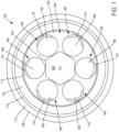
- the micro-reactor 100 can include a reactor core 102 that can house fuel, moderator channels, heat pipes and reactivity control channels (shutdown rods).
- the reactor core 102 can be similar to reactor cores described in U.S. Provisional Application Publication No. 62/984,591 and in U.S. Patent Application No. 14/773,405 .
- the reactor core 102 can include a reactor core housing, or shell 104, that can house the fuel, the plurality of heat pipes, the plurality of moderator channels and the plurality of reactivity control channels in the reactor core 102.
- the fuel can be encapsulated in the core 102 while the heat pipes, moderator channels and reactivity control channels can extend outside of the core 102 to a secondary side of the micro-reactor 100 so as to allow for extraction of heat generated by the fuel.
- the micro-reactor 100 can include an enhanced neutron reflector assembly 150 surrounding the reactor core 102.
- the reflector assembly 150 can include both a stationary reflector component 152 and a movable reflector component 154.
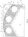
- the stationary reflector component 152 can include a graphite support structure 156 that can include a plurality of channels 158 defined therein.
- the graphite support structure 156 can be of unitary construction.
- the graphite support structure 156 can be assembled from a plurality of smaller, graphite support structure components pieced together to form the graphite support structure 156. Having the graphite support structure 156 being formed from a plurality of smaller, graphite support components can assist in the manufacturing process and can be used to provide the spacing for other components within the stationary reflector component 152, such as the movable reflector component 154, as will be described in more detail below.
- the graphite support structure 156 can be formed from a plurality of smaller, graphite support components such that the individual components are positioned to provide continuous neutronic reflection.
- the plurality of smaller, graphite support components can be positioned in both the radial and the axial direction relative to the reactor core 102 so as to provide continuous neutronic reflection.
- assembling the graphite support structure 156 from a plurality of smaller graphite support structure components allows for overlapping gaps to be left between the individual components. These gaps between the smaller graphite support components can be selected to provide a continuous neutronic reflection in case of differential thermal expansion between core 102 and reflector assembly 150, as well as support mechanical load transfer and heat removal.
- graphite support structure 156 can include a radial thickness in the range of about 0.3 meters to about 1.0 meters. Other embodiments are envisioned where the radial thickness of the graphite support structure 156 can be greater than 1.0 meters or less than 0.3 meters.
- the reflector assembly 150 can further include a plurality of beryllium oxide inclusions, pins or inserts 160, that can be removably positioned in the channels 158 defined by the graphite support structure 156.
- any type of beryllium-based or beryllium-oxide inclusion can be used.
- the graphite support structure 156 can act a support structure for supporting the beryllium oxide inclusions 160, such as in the channels 158, while also supporting neutronic reflection from the reactor core 102 and providing for mechanical and thermal load transfer.
- the micro-reactor 100 can further include a movable reflector component 154.
- the movable reflector component 154 can comprise a plurality of control drums 106 that can be rotatably positioned within the stationary reflector component 152.
- the control drums 106 can include a neutron absorber section 110 and a neutron reflector section 108.
- the control drums 106 can each be rotatable relative to the stationary reflector component 152 between a neutron reflecting position and a neutron absorbing position. In the neutron reflecting position, the neutron reflector sections 108 of the control drums 106 can face the reactor core 102, thus increasing reactivity of the reactor core 102.
- the neutron absorber sections 110 can face the reactor core 102, limiting or stopping reactivity within the reactor core 102.
- the neutron reflector sections 108 can comprise beryllium-oxide.
- the neutron reflector sections 108 can be manufactured out of graphite and include channels defined therein, similar to the graphite support structure 156.
- beryllium-oxide includes can be positioned in the channels defined in the graphite control drums.
- the neutron reflector sections 108 of the controls drums 106 can be manufactured substantially, if not entirely, out of beryllium-oxide.
- control drums 106 can be the only movable component within the reactor core 102. In one embodiment, all of the control drums 106 can rotate together such that all of control drums 106 are either in the neutron reflecting position or the neutron absorbing position. In other embodiments, the control drums 106 can be independently rotatable relative to each other. In other embodiments, the control drums 106 can be rotated to a partially rotated position where a portion of both the neutron absorber section 110 and neutron reflector section 108 are at least partially facing the reactor core, thus allowing for an intermediate level of reactivity within the reactor core 102.
- control drums 106 can automatically rotate between the neutron reflecting position and the neutron absorbing position depending on various factors, such as the temperature within the reactor core 102. In one aspect, when the temperature within the reactor core 102 meets or exceeds a threshold temperature, the control drums 106 can be automatically rotate to the neutron absorbing position. In another aspect, when the temperature within the reactor core 102 drops below a threshold temperature, the control drums 106 can automatically rotate to the neutron reflecting position. Various other embodiments are envisioned where the control drums 106 can rotate between the neutron absorbing position and the neutron reflecting position based on other measured parameters within the reactor. As one example, the control drums 106 can be rotatable between the neutron absorbing position and the neutron reflecting position based on measured neutron flex within the micro-reactor 100.
- the reactor core 102 and the enhanced neutron reflector assembly 150 can be housed within a structural container 112, a neutron absorber vessel 122, and a boron carbide, or gamma, neutron shield 114.
- an air gap 116 can be provided between the neutron absorber vessel 122 and the boron carbide shield 114 for shield cooling and gamma shielding. All these components can be placed inside of an outer structural canister 120.
- the reactor core 102 and the enhanced neutron reflector assembly 150 could also be housed in the housings described in U.S. Provisional Application Publication No. 62/984,591 , as well as in U.S. Patent Application No. 14/773,405 .
- the reactor core housing 104 can also comprise beryllium-oxide.
- the channels 158 defined in the graphite support structure 156 can be sized and positioned such that a good neutron performance of the reflector assembly 150 can be achieved with the beryllium oxide inclusions 160.
- selection of the channels 158 diameter, pitch, and spacing relative to adjacent channels 158 can be varied to optimize performance of the reflector assembly 150.
- the channels 158 can be placed in triangle or rectangle pitch as uniformly as practically possible taking into account provisions for the movable reflector component 154 and split stationary reflector parts, as well as a thermal assessment of the reactor core.
- the pitch of the channels 158 can be in the range of about 0.013 meters to about 0.07 meters.
- the diameter of the channels 158 can be in the range of about 0.005 meters to about 0.05 meters. In other embodiments, the diameter of the beryllium oxide inclusions 160 and diameter of the channels 158 can be different.
- channels 158 defined in the graphite support structure 156 can be spaced apart from adjacent channels 158 in the range of 0.001 meters to about 0.06 meters apart. In one aspect, the spacing of the channels 158 can be defined as the space between an outer edge of one channel 158 relative to an outer edge of an adjacent channel 158. In various embodiments, the above discussed parameters (diameter, pitch and channel spacing) in the graphite support structure 156 can vary from channel to channel.
- the advantages of this concept include, but are not limited to, an ability to maintain relatively small dimensions of the neutron reflector itself, an ability to maintain a relatively small amount of fuel for providing the required thermal power, an improved manufacturability and assembling of the reflector, and improved thermo-mechanical performance, and a reduced reflector cost.
- the combination of materials allow for good neutron reflection, an acceptable thermo-mechanical performance and a feasibility of manufacturing and assembling that would be very beneficial.
- Example 1 A nuclear reactor comprising a reactor core and a reflector assembly surrounding the reactor core, wherein the reflector assembly comprises a stationary reflector component comprising a graphite support structure comprising a plurality of channels defined therein and a plurality of beryllium-oxide pins positioned in the channels.
- the reflector assembly comprises a stationary reflector component comprising a graphite support structure comprising a plurality of channels defined therein and a plurality of beryllium-oxide pins positioned in the channels.
- Example 2 The nuclear reactor of Example 1, wherein the reflector assembly further comprises a movable reflector component, wherein the movable reflector component comprises a plurality of control drums rotatable relative to the stationary reflector component.
- Example 3 The nuclear reactor of Example 2, wherein each of the control drums comprises a reflector portion and an absorber portion, wherein the reflector portion comprises beryllium-oxide.
- Example 4 The nuclear reactor of any one of Examples 1-3, further comprising a reactor core housing, wherein the reactor core is positioned within the reactor core housing, and wherein the reactor core housing comprises beryllium-oxide.
- Example 5 The nuclear reactor of any one of Examples 1-4, wherein the graphite support structure comprises a radial thickness of about 0.3 meters to about 1.0 meters.
- Example 6 The nuclear reactor of any one of Examples 1-5, wherein each of the plurality of channels comprises a diameter, and wherein the diameter is about 0.005 meters to about 0.05 meters.
- Example 7 The nuclear reactor of any one of Examples 1-6, wherein each of the plurality of channels comprises a pitch, and wherein the pitch is about 0.013 meters to about 0.07 meters.
- Example 8 The nuclear reactor of any one of Examples 1-7, wherein each of the plurality of channels are spaced apart from each other by about 0.001 meters to about 0.06 meters.
- Example 9 The nuclear reactor of any one of Examples 1-8, wherein the graphite support structure is an assembly comprised of a plurality of graphite support structures positioned to provide continuous neutronic reflection.
- Example 10 A reflector assembly usable with a nuclear reactor comprising a reactor core, wherein the reflector assembly is configured to surround the reactor core, and wherein the reflector assembly comprises a graphite support structure comprising a plurality of channels defined therein and a plurality of beryllium-oxide inclusions positioned in the channels.
- Example 11 The reflector assembly of Example 10, further comprising a plurality of control drums rotatable relative to the graphite support structure.
- Example 12 The reflector assembly of Example 11, wherein each of the control drums comprises a reflector portion and an absorber portion, and wherein the reflector portion comprises beryllium-oxide.
- Example 13 The reflector assembly of any one of Examples 10-12, wherein the graphite support structure comprises a radial thickness of about 0.3 meters to about 1.0 meters.
- Example 14 The reflector assembly of any one of Examples 10-13, wherein each of the plurality of channels comprises a diameter, and wherein the diameter is about 0.005 meters to about 0.05 meters.
- Example 15 The reflector assembly of any one of Examples 10-14, wherein each of the plurality of channels comprises a pitch, and wherein the pitch is about 0.013 meters to about 0.07 meters.
- Example 16 The reflector assembly of any one of Examples 10-15, wherein each of the plurality of channels are spaced apart from each other by about 0.001 meters to about 0.06 meters.
- Example 17 The reflector assembly of any one of Examples 10-16, wherein the graphite support structure is an assembly comprised of a plurality of graphite support structures positioned to provide continuous neutronic reflection.
- Example 18 - A nuclear reactor comprising a reactor core and a reflector assembly surrounding the reactor core, wherein the reflector assembly comprises a stationary reflector portion and a movable reflector portion.
- the stationary reflector portion comprises a graphite support structure comprising a plurality of channels defined therein and a plurality of beryllium-oxide inserts positioned in the channels.
- the movable reflector portion comprises a plurality of control drums rotatable relative to the stationary reflector portion.
- Example 19 The nuclear reactor of Example 18, wherein each of the control drums comprises a reflector portion and an absorber portion, and wherein the reflector portion comprises beryllium-oxide.
- Example 20 The nuclear reactor of Examples 18 or 19, further comprising a reactor core housing, wherein the reactor core is positioned within the reactor core housing, and wherein the reactor core housing comprises beryllium-oxide.
- One or more components may be referred to herein as “configured to,” “configurable to,” “operable/operative to,” “adapted/adaptable,” “able to,” “conformable/conformed to,” etc.
- “configured to” can generally encompass active-state components and/or inactive-state components and/or standby-state components, unless context requires otherwise.
- any reference to “one aspect,” “an aspect,” “an exemplification,” “one exemplification,” and the like means that a particular feature, structure, or characteristic described in connection with the aspect is included in at least one aspect.
- appearances of the phrases “in one aspect,” “in an aspect,” “in an exemplification,” and “in one exemplification” in various places throughout the specification are not necessarily all referring to the same aspect.
- the particular features, structures or characteristics may be combined in any suitable manner in one or more aspects.
- the term “substantially”, “about”, or “approximately” as used in the present disclosure means an acceptable error for a particular value as determined by one of ordinary skill in the art, which depends in part on how the value is measured or determined. In certain embodiments, the term “substantially”, “about”, or “approximately” means within 1, 2, 3, or 4 standard deviations. In certain embodiments, the term “substantially”, “about”, or “approximately” means within 50%, 20%, 15%, 10%, 9%, 8%, 7%, 6%, 5%, 4%, 3%, 2%, 1%, 0.5%, or 0.05% of a given value or range.
Landscapes
- Physics & Mathematics (AREA)
- Engineering & Computer Science (AREA)
- Plasma & Fusion (AREA)
- General Engineering & Computer Science (AREA)
- High Energy & Nuclear Physics (AREA)
- Chemical & Material Sciences (AREA)
- Chemical Kinetics & Catalysis (AREA)
- Monitoring And Testing Of Nuclear Reactors (AREA)
- Carbon And Carbon Compounds (AREA)
Applications Claiming Priority (3)
| Application Number | Priority Date | Filing Date | Title |
|---|---|---|---|
| US17/080,241 US11830630B2 (en) | 2020-10-26 | 2020-10-26 | Enhanced graphite neutron reflector with beryllium oxide inclusions |
| PCT/US2021/072035 WO2022094552A1 (en) | 2020-10-26 | 2021-10-26 | Enhanced graphite neutron reflector with beryllium oxide inclusions |
| EP21811220.9A EP4233073B1 (de) | 2020-10-26 | 2021-10-26 | Verbesserter graphitneutronenreflektor mit berylliumoxideinschlüssen |
Related Parent Applications (1)
| Application Number | Title | Priority Date | Filing Date |
|---|---|---|---|
| EP21811220.9A Division EP4233073B1 (de) | 2020-10-26 | 2021-10-26 | Verbesserter graphitneutronenreflektor mit berylliumoxideinschlüssen |
Publications (3)
| Publication Number | Publication Date |
|---|---|
| EP4447070A2 true EP4447070A2 (de) | 2024-10-16 |
| EP4447070A3 EP4447070A3 (de) | 2024-12-11 |
| EP4447070B1 EP4447070B1 (de) | 2026-02-18 |
Family
ID=78709578
Family Applications (2)
| Application Number | Title | Priority Date | Filing Date |
|---|---|---|---|
| EP21811220.9A Active EP4233073B1 (de) | 2020-10-26 | 2021-10-26 | Verbesserter graphitneutronenreflektor mit berylliumoxideinschlüssen |
| EP24191911.7A Active EP4447070B1 (de) | 2020-10-26 | 2021-10-26 | Verbesserter graphitneutronenreflektor mit berylliumoxideinschlüssen |
Family Applications Before (1)
| Application Number | Title | Priority Date | Filing Date |
|---|---|---|---|
| EP21811220.9A Active EP4233073B1 (de) | 2020-10-26 | 2021-10-26 | Verbesserter graphitneutronenreflektor mit berylliumoxideinschlüssen |
Country Status (8)
| Country | Link |
|---|---|
| US (1) | US11830630B2 (de) |
| EP (2) | EP4233073B1 (de) |
| JP (1) | JP7733729B2 (de) |
| KR (1) | KR20230093440A (de) |
| CA (1) | CA3196663A1 (de) |
| ES (1) | ES2998744T3 (de) |
| TW (1) | TWI803029B (de) |
| WO (1) | WO2022094552A1 (de) |
Cited By (1)
| Publication number | Priority date | Publication date | Assignee | Title |
|---|---|---|---|---|
| US20240170167A1 (en) * | 2021-03-15 | 2024-05-23 | "Akme-Engineering", Joint-Stock Company | Nuclear reactor with a heavy liquid metal coolant |
Citations (2)
| Publication number | Priority date | Publication date | Assignee | Title |
|---|---|---|---|---|
| US20150357056A1 (en) | 2014-04-09 | 2015-12-10 | Colorado School Of Mines | Reactor unit control system for space and terrestrial applications |
| US20160027536A1 (en) | 2013-04-25 | 2016-01-28 | Los Alamos National Security , LLC | Mobile heat pipe cooled fast reactor system |
Family Cites Families (23)
| Publication number | Priority date | Publication date | Assignee | Title |
|---|---|---|---|---|
| US2992982A (en) * | 1957-12-10 | 1961-07-18 | Avery Robert | Coupled fast-thermal power breeder reactor |
| BE588349A (de) * | 1959-03-10 | |||
| US3296083A (en) | 1964-09-14 | 1967-01-03 | Gen Dynamics Corp | Forced circulation boiling nuclear power reactor |
| US4314883A (en) * | 1978-11-30 | 1982-02-09 | Hochtemperatur-Reaktorbau Gmbh. | Graphite block having wear zone and load bearing zone for side reflector of high temperature reactor |
| DE3009390A1 (de) * | 1980-03-12 | 1981-09-17 | GHT Gesellschaft für Hochtemperaturreaktor-Technik mbH, 5060 Bergisch Gladbach | Hochtemperaturreaktor |
| US4751043A (en) * | 1984-02-03 | 1988-06-14 | Westinghouse Electric Corp. | Radial neutron reflector |
| US4849162A (en) * | 1984-11-13 | 1989-07-18 | Westinghouse Electric Corp. | Modular radial neutron reflector |
| DE3518968A1 (de) * | 1985-05-25 | 1986-11-27 | Hochtemperatur-Reaktorbau GmbH, 4600 Dortmund | Unterirdisch in der kaverne eines zylindrischen druckbehaelters angeordneter kernreaktor niedriger leistung |
| JP2946394B2 (ja) * | 1994-10-31 | 1999-09-06 | 原子燃料工業株式会社 | 原子炉出力制御機構 |
| US20040062340A1 (en) * | 2002-09-16 | 2004-04-01 | Peterson Otis G. | Self-regulating nuclear power module |
| WO2011097493A1 (en) * | 2010-02-04 | 2011-08-11 | General Atomics | Modular nuclear fission waste conversion reactor |
| JP2011174728A (ja) * | 2010-02-23 | 2011-09-08 | Toshiba Corp | 反射体制御型原子炉 |
| RU2562617C2 (ru) * | 2010-06-04 | 2015-09-10 | Пеббл Бед Модулар Риэктор Сок Лтд | Сборка блока отражателя нейтронов, боковой отражатель ядерного реактора и ядерный реактор |
| US9093183B2 (en) * | 2012-12-20 | 2015-07-28 | Westinghouse Electric Company Llc | Heavy radial neutron reflector for pressurized water reactors |
| US20150243376A1 (en) * | 2014-02-26 | 2015-08-27 | Taylor Ramon WILSON | Molten salt fission reactor |
| KR101704658B1 (ko) | 2015-03-25 | 2017-02-08 | 세종대학교산학협력단 | 자발핵분열 중성자원을 이용한 소형 모듈화 원자로 노심 및 이를 포함하는 원자로 |
| US10522259B2 (en) * | 2015-04-02 | 2019-12-31 | Clear Inc. | Nuclear power generation system utilizing thermal expansion in metallic members to move a neutron reflector |
| EP3485496B1 (de) * | 2016-07-15 | 2020-04-15 | TerraPower, LLC | Vertikal segmentierter kernreaktor |
| EP3513409A4 (de) | 2016-09-13 | 2020-03-04 | Westinghouse Electric Company Llc | Wärmerohr-flüssigsalzschnellreaktor mit stehendem flüssigem kern |
| US10559389B2 (en) * | 2017-02-06 | 2020-02-11 | Battell Energy Alliance, LLC | Modular nuclear reactors including fuel elements and heat pipes extending through grid plates, and methods of forming the modular nuclear reactors |
| US10910116B2 (en) * | 2017-03-16 | 2021-02-02 | Battelle Energy Alliance, Llc | Nuclear reactors including heat exchangers and heat pipes extending from a core of the nuclear reactor into the heat exchanger and related methods |
| US11990248B2 (en) * | 2019-08-29 | 2024-05-21 | BWXT Advanced Technologies LLC | Robust nuclear propulsion fission reactor with tri-pitch patterned core and drum absorbers |
| WO2021055588A1 (en) * | 2019-09-17 | 2021-03-25 | Bwxt Advanced Technologies, Llc | Control drum system for use with nuclear reactors |
-
2020
- 2020-10-26 US US17/080,241 patent/US11830630B2/en active Active
-
2021
- 2021-10-26 ES ES21811220T patent/ES2998744T3/es active Active
- 2021-10-26 JP JP2023525110A patent/JP7733729B2/ja active Active
- 2021-10-26 KR KR1020237014428A patent/KR20230093440A/ko active Pending
- 2021-10-26 EP EP21811220.9A patent/EP4233073B1/de active Active
- 2021-10-26 TW TW110139687A patent/TWI803029B/zh active
- 2021-10-26 CA CA3196663A patent/CA3196663A1/en active Pending
- 2021-10-26 EP EP24191911.7A patent/EP4447070B1/de active Active
- 2021-10-26 WO PCT/US2021/072035 patent/WO2022094552A1/en not_active Ceased
Patent Citations (2)
| Publication number | Priority date | Publication date | Assignee | Title |
|---|---|---|---|---|
| US20160027536A1 (en) | 2013-04-25 | 2016-01-28 | Los Alamos National Security , LLC | Mobile heat pipe cooled fast reactor system |
| US20150357056A1 (en) | 2014-04-09 | 2015-12-10 | Colorado School Of Mines | Reactor unit control system for space and terrestrial applications |
Cited By (1)
| Publication number | Priority date | Publication date | Assignee | Title |
|---|---|---|---|---|
| US20240170167A1 (en) * | 2021-03-15 | 2024-05-23 | "Akme-Engineering", Joint-Stock Company | Nuclear reactor with a heavy liquid metal coolant |
Also Published As
| Publication number | Publication date |
|---|---|
| US11830630B2 (en) | 2023-11-28 |
| CA3196663A1 (en) | 2022-05-05 |
| EP4447070B1 (de) | 2026-02-18 |
| EP4233073A1 (de) | 2023-08-30 |
| TW202223923A (zh) | 2022-06-16 |
| US20220130561A1 (en) | 2022-04-28 |
| KR20230093440A (ko) | 2023-06-27 |
| EP4233073B1 (de) | 2024-08-21 |
| JP2023546726A (ja) | 2023-11-07 |
| TWI803029B (zh) | 2023-05-21 |
| JP7733729B2 (ja) | 2025-09-03 |
| EP4447070A3 (de) | 2024-12-11 |
| WO2022094552A1 (en) | 2022-05-05 |
| ES2998744T3 (en) | 2025-02-21 |
Similar Documents
| Publication | Publication Date | Title |
|---|---|---|
| EP4229658B1 (de) | Hochtemperatur-hydridmoderator mit kompakten und höheren leistungsdichtekernen in kernreaktoren | |
| US11075015B2 (en) | Reflectors for molten chloride fast reactors | |
| US20240312648A1 (en) | NUCLEAR FUEL RODS AND HEAT PIPES IN A GRAPHITE MODERATOR MATRIX FOR A MICRO-REACTOR, WITH THE FUEL RODS HAVING FUEL PELLETS IN A BeO SLEEVE | |
| US11417435B2 (en) | Control drum for a mobile nuclear reactor | |
| EP4447070B1 (de) | Verbesserter graphitneutronenreflektor mit berylliumoxideinschlüssen | |
| EP4697360A1 (de) | Kernstruktur eines kernkraftwerksreaktors und verarbeitungsverfahren dafür | |
| JP2024504432A (ja) | マイクロ原子炉炉心の機械的支持 | |
| Youji et al. | Development of water-cooled cylindrical blanket in JA DEMO | |
| Choi et al. | Progress in fast modular reactor conceptual design | |
| KR100901812B1 (ko) | 연료봉 안정지지 및 프레팅 마모방지를 위한 이중날개모양의 스프링을 가진 지지격자 | |
| KR20250038622A (ko) | 혼합 스펙트럼 용융염 원자로 | |
| US8335293B1 (en) | Nuclear fuel grid assembly with hydraulically balanced mixing vane pattern | |
| Hoang | Core Design of a Small Pressurized Water Reactor with AP1000 Fuel Assembly Using SRAC and COBRA‐EN Codes | |
| JP2024175507A (ja) | 原子炉および原子炉の制御方法 | |
| CN121617671A (zh) | 燃料组件及反应堆 | |
| Dabby | Fuel utilization improvements in a once-through PWR fuel cycle. Final report on Task 6 | |
| Vitti et al. | Nuclear Design and Economic Comparison of a Conventional and Bullseye Liquid-Metal Fast Breeder Reactor Core | |
| Kloosterman et al. | Innovative Gas-Cooled Reactors | |
| Bliss et al. | A utility assessment of the Modular High-Temperature Gas-Cooled Reactor (MHTGR) | |
| Durkosh | PWR radiation fields through 1982.[Westinghouse reactors] |
Legal Events
| Date | Code | Title | Description |
|---|---|---|---|
| PUAI | Public reference made under article 153(3) epc to a published international application that has entered the european phase |
Free format text: ORIGINAL CODE: 0009012 |
|
| STAA | Information on the status of an ep patent application or granted ep patent |
Free format text: STATUS: THE APPLICATION HAS BEEN PUBLISHED |
|
| AC | Divisional application: reference to earlier application |
Ref document number: 4233073 Country of ref document: EP Kind code of ref document: P |
|
| AK | Designated contracting states |
Kind code of ref document: A2 Designated state(s): AL AT BE BG CH CY CZ DE DK EE ES FI FR GB GR HR HU IE IS IT LI LT LU LV MC MK MT NL NO PL PT RO RS SE SI SK SM TR |
|
| PUAL | Search report despatched |
Free format text: ORIGINAL CODE: 0009013 |
|
| AK | Designated contracting states |
Kind code of ref document: A3 Designated state(s): AL AT BE BG CH CY CZ DE DK EE ES FI FR GB GR HR HU IE IS IT LI LT LU LV MC MK MT NL NO PL PT RO RS SE SI SK SM TR |
|
| RIC1 | Information provided on ipc code assigned before grant |
Ipc: G21C 1/06 20060101ALI20241107BHEP Ipc: G21C 7/28 20060101ALI20241107BHEP Ipc: G21C 7/103 20060101ALI20241107BHEP Ipc: G21C 11/06 20060101AFI20241107BHEP |
|
| STAA | Information on the status of an ep patent application or granted ep patent |
Free format text: STATUS: REQUEST FOR EXAMINATION WAS MADE |
|
| 17P | Request for examination filed |
Effective date: 20250523 |
|
| GRAP | Despatch of communication of intention to grant a patent |
Free format text: ORIGINAL CODE: EPIDOSNIGR1 |
|
| STAA | Information on the status of an ep patent application or granted ep patent |
Free format text: STATUS: GRANT OF PATENT IS INTENDED |
|
| INTG | Intention to grant announced |
Effective date: 20250909 |
|
| GRAS | Grant fee paid |
Free format text: ORIGINAL CODE: EPIDOSNIGR3 |
|
| GRAA | (expected) grant |
Free format text: ORIGINAL CODE: 0009210 |
|
| STAA | Information on the status of an ep patent application or granted ep patent |
Free format text: STATUS: THE PATENT HAS BEEN GRANTED |
|
| P01 | Opt-out of the competence of the unified patent court (upc) registered |
Free format text: CASE NUMBER: UPC_APP_0019627_4447070/2025 Effective date: 20251230 |
|
| AC | Divisional application: reference to earlier application |
Ref document number: 4233073 Country of ref document: EP Kind code of ref document: P |
|
| AK | Designated contracting states |
Kind code of ref document: B1 Designated state(s): AL AT BE BG CH CY CZ DE DK EE ES FI FR GB GR HR HU IE IS IT LI LT LU LV MC MK MT NL NO PL PT RO RS SE SI SK SM TR |
|
| REG | Reference to a national code |
Ref country code: CH Ref legal event code: F10 Free format text: ST27 STATUS EVENT CODE: U-0-0-F10-F00 (AS PROVIDED BY THE NATIONAL OFFICE) Effective date: 20260218 Ref country code: GB Ref legal event code: FG4D |
|
| REG | Reference to a national code |
Ref country code: IE Ref legal event code: FG4D |
|
| REG | Reference to a national code |
Ref country code: DE Ref legal event code: R096 Ref document number: 602021048508 Country of ref document: DE |