EP4446572A1 - Butterfly valve - Google Patents
Butterfly valve Download PDFInfo
- Publication number
- EP4446572A1 EP4446572A1 EP23746827.7A EP23746827A EP4446572A1 EP 4446572 A1 EP4446572 A1 EP 4446572A1 EP 23746827 A EP23746827 A EP 23746827A EP 4446572 A1 EP4446572 A1 EP 4446572A1
- Authority
- EP
- European Patent Office
- Prior art keywords
- bush
- sealing bush
- valve shaft
- valve
- exhaust pipe
- Prior art date
- Legal status (The legal status is an assumption and is not a legal conclusion. Google has not performed a legal analysis and makes no representation as to the accuracy of the status listed.)
- Pending
Links
Images




Classifications
-
- F—MECHANICAL ENGINEERING; LIGHTING; HEATING; WEAPONS; BLASTING
- F02—COMBUSTION ENGINES; HOT-GAS OR COMBUSTION-PRODUCT ENGINE PLANTS
- F02D—CONTROLLING COMBUSTION ENGINES
- F02D9/00—Controlling engines by throttling air or fuel-and-air induction conduits or exhaust conduits
- F02D9/08—Throttle valves specially adapted therefor; Arrangements of such valves in conduits
- F02D9/10—Throttle valves specially adapted therefor; Arrangements of such valves in conduits having pivotally-mounted flaps
- F02D9/1035—Details of the valve housing
- F02D9/106—Sealing of the valve shaft in the housing, e.g. details of the bearings
-
- F—MECHANICAL ENGINEERING; LIGHTING; HEATING; WEAPONS; BLASTING
- F01—MACHINES OR ENGINES IN GENERAL; ENGINE PLANTS IN GENERAL; STEAM ENGINES
- F01N—GAS-FLOW SILENCERS OR EXHAUST APPARATUS FOR MACHINES OR ENGINES IN GENERAL; GAS-FLOW SILENCERS OR EXHAUST APPARATUS FOR INTERNAL-COMBUSTION ENGINES
- F01N13/00—Exhaust or silencing apparatus characterised by constructional features
- F01N13/08—Other arrangements or adaptations of exhaust conduits
-
- F—MECHANICAL ENGINEERING; LIGHTING; HEATING; WEAPONS; BLASTING
- F02—COMBUSTION ENGINES; HOT-GAS OR COMBUSTION-PRODUCT ENGINE PLANTS
- F02D—CONTROLLING COMBUSTION ENGINES
- F02D9/00—Controlling engines by throttling air or fuel-and-air induction conduits or exhaust conduits
- F02D9/04—Controlling engines by throttling air or fuel-and-air induction conduits or exhaust conduits concerning exhaust conduits
-
- F—MECHANICAL ENGINEERING; LIGHTING; HEATING; WEAPONS; BLASTING
- F02—COMBUSTION ENGINES; HOT-GAS OR COMBUSTION-PRODUCT ENGINE PLANTS
- F02D—CONTROLLING COMBUSTION ENGINES
- F02D9/00—Controlling engines by throttling air or fuel-and-air induction conduits or exhaust conduits
- F02D9/08—Throttle valves specially adapted therefor; Arrangements of such valves in conduits
- F02D9/10—Throttle valves specially adapted therefor; Arrangements of such valves in conduits having pivotally-mounted flaps
- F02D9/1075—Materials, e.g. composites
- F02D9/1085—Non-organic materials, e.g. metals, alloys, ceramics
-
- F—MECHANICAL ENGINEERING; LIGHTING; HEATING; WEAPONS; BLASTING
- F16—ENGINEERING ELEMENTS AND UNITS; GENERAL MEASURES FOR PRODUCING AND MAINTAINING EFFECTIVE FUNCTIONING OF MACHINES OR INSTALLATIONS; THERMAL INSULATION IN GENERAL
- F16C—SHAFTS; FLEXIBLE SHAFTS; ELEMENTS OR CRANKSHAFT MECHANISMS; ROTARY BODIES OTHER THAN GEARING ELEMENTS; BEARINGS
- F16C33/00—Parts of bearings; Special methods for making bearings or parts thereof
- F16C33/72—Sealings
- F16C33/74—Sealings of sliding-contact bearings
-
- F—MECHANICAL ENGINEERING; LIGHTING; HEATING; WEAPONS; BLASTING
- F16—ENGINEERING ELEMENTS AND UNITS; GENERAL MEASURES FOR PRODUCING AND MAINTAINING EFFECTIVE FUNCTIONING OF MACHINES OR INSTALLATIONS; THERMAL INSULATION IN GENERAL
- F16J—PISTONS; CYLINDERS; SEALINGS
- F16J15/00—Sealings
- F16J15/16—Sealings between relatively-moving surfaces
- F16J15/34—Sealings between relatively-moving surfaces with slip-ring pressed against a more or less radial face on one member
- F16J15/3464—Mounting of the seal
- F16J15/3472—Means for centering or aligning the contacting faces
-
- F—MECHANICAL ENGINEERING; LIGHTING; HEATING; WEAPONS; BLASTING
- F16—ENGINEERING ELEMENTS AND UNITS; GENERAL MEASURES FOR PRODUCING AND MAINTAINING EFFECTIVE FUNCTIONING OF MACHINES OR INSTALLATIONS; THERMAL INSULATION IN GENERAL
- F16K—VALVES; TAPS; COCKS; ACTUATING-FLOATS; DEVICES FOR VENTING OR AERATING
- F16K1/00—Lift valves or globe valves, i.e. cut-off apparatus with closure members having at least a component of their opening and closing motion perpendicular to the closing faces
- F16K1/16—Lift valves or globe valves, i.e. cut-off apparatus with closure members having at least a component of their opening and closing motion perpendicular to the closing faces with pivoted closure-members
- F16K1/18—Lift valves or globe valves, i.e. cut-off apparatus with closure members having at least a component of their opening and closing motion perpendicular to the closing faces with pivoted closure-members with pivoted discs or flaps
- F16K1/22—Lift valves or globe valves, i.e. cut-off apparatus with closure members having at least a component of their opening and closing motion perpendicular to the closing faces with pivoted closure-members with pivoted discs or flaps with axis of rotation crossing the valve member, e.g. butterfly valves
- F16K1/224—Details of bearings for the axis of rotation
-
- F—MECHANICAL ENGINEERING; LIGHTING; HEATING; WEAPONS; BLASTING
- F16—ENGINEERING ELEMENTS AND UNITS; GENERAL MEASURES FOR PRODUCING AND MAINTAINING EFFECTIVE FUNCTIONING OF MACHINES OR INSTALLATIONS; THERMAL INSULATION IN GENERAL
- F16K—VALVES; TAPS; COCKS; ACTUATING-FLOATS; DEVICES FOR VENTING OR AERATING
- F16K1/00—Lift valves or globe valves, i.e. cut-off apparatus with closure members having at least a component of their opening and closing motion perpendicular to the closing faces
- F16K1/16—Lift valves or globe valves, i.e. cut-off apparatus with closure members having at least a component of their opening and closing motion perpendicular to the closing faces with pivoted closure-members
- F16K1/18—Lift valves or globe valves, i.e. cut-off apparatus with closure members having at least a component of their opening and closing motion perpendicular to the closing faces with pivoted closure-members with pivoted discs or flaps
- F16K1/22—Lift valves or globe valves, i.e. cut-off apparatus with closure members having at least a component of their opening and closing motion perpendicular to the closing faces with pivoted closure-members with pivoted discs or flaps with axis of rotation crossing the valve member, e.g. butterfly valves
- F16K1/226—Shaping or arrangements of the sealing
- F16K1/2268—Sealing means for the axis of rotation
-
- F—MECHANICAL ENGINEERING; LIGHTING; HEATING; WEAPONS; BLASTING
- F01—MACHINES OR ENGINES IN GENERAL; ENGINE PLANTS IN GENERAL; STEAM ENGINES
- F01N—GAS-FLOW SILENCERS OR EXHAUST APPARATUS FOR MACHINES OR ENGINES IN GENERAL; GAS-FLOW SILENCERS OR EXHAUST APPARATUS FOR INTERNAL-COMBUSTION ENGINES
- F01N2240/00—Combination or association of two or more different exhaust treating devices, or of at least one such device with an auxiliary device, not covered by indexing codes F01N2230/00 or F01N2250/00, one of the devices being
- F01N2240/20—Combination or association of two or more different exhaust treating devices, or of at least one such device with an auxiliary device, not covered by indexing codes F01N2230/00 or F01N2250/00, one of the devices being a flow director or deflector
-
- F—MECHANICAL ENGINEERING; LIGHTING; HEATING; WEAPONS; BLASTING
- F02—COMBUSTION ENGINES; HOT-GAS OR COMBUSTION-PRODUCT ENGINE PLANTS
- F02D—CONTROLLING COMBUSTION ENGINES
- F02D9/00—Controlling engines by throttling air or fuel-and-air induction conduits or exhaust conduits
- F02D9/04—Controlling engines by throttling air or fuel-and-air induction conduits or exhaust conduits concerning exhaust conduits
- F02D9/06—Exhaust brakes
-
- F—MECHANICAL ENGINEERING; LIGHTING; HEATING; WEAPONS; BLASTING
- F02—COMBUSTION ENGINES; HOT-GAS OR COMBUSTION-PRODUCT ENGINE PLANTS
- F02D—CONTROLLING COMBUSTION ENGINES
- F02D9/00—Controlling engines by throttling air or fuel-and-air induction conduits or exhaust conduits
- F02D9/08—Throttle valves specially adapted therefor; Arrangements of such valves in conduits
- F02D9/10—Throttle valves specially adapted therefor; Arrangements of such valves in conduits having pivotally-mounted flaps
- F02D9/1065—Mechanical control linkage between an actuator and the flap, e.g. including levers, gears, springs, clutches, limit stops of the like
-
- Y—GENERAL TAGGING OF NEW TECHNOLOGICAL DEVELOPMENTS; GENERAL TAGGING OF CROSS-SECTIONAL TECHNOLOGIES SPANNING OVER SEVERAL SECTIONS OF THE IPC; TECHNICAL SUBJECTS COVERED BY FORMER USPC CROSS-REFERENCE ART COLLECTIONS [XRACs] AND DIGESTS
- Y02—TECHNOLOGIES OR APPLICATIONS FOR MITIGATION OR ADAPTATION AGAINST CLIMATE CHANGE
- Y02T—CLIMATE CHANGE MITIGATION TECHNOLOGIES RELATED TO TRANSPORTATION
- Y02T10/00—Road transport of goods or passengers
- Y02T10/10—Internal combustion engine [ICE] based vehicles
- Y02T10/12—Improving ICE efficiencies
Definitions
- the present invention relates to a butterfly valve, and more particularly, to a butterfly valve that opens and closes an exhaust pipe communicating with an exhaust port of an engine.
- an exhaust device that controls a flow of exhaust gas in an exhaust pipe communicating with an exhaust port of an engine of an automatic two-wheeled vehicle
- an exhaust device comprising: a valve body (valve plate) arranged in the exhaust pipe; a valve shaft that is fixed to or integrated with the valve body and is arranged to cross the exhaust pipe; and a pair of bearing members that rotatably support both axial ends of the valve shaft, wherein the valve body is rotated around the valve shaft (for example, in the patent literature 1.).
- Patent Literature 1 JP 2008-169797 A (for example, see Fig. 5 )
- a butterfly valve as described above is installed in an exhaust pipe communicating with an exhaust port of an engine of an automatic four-wheeled vehicle, since the back pressure will be greater than that in an automatic two-wheeled vehicle, when the valve body closes the exhaust pipe, there is possibility that the bearing member will not be able to withstand a radial load caused by the back pressure.
- an object of the present invention is to provide a butterfly valve with which the exhaust gas is hard to leak out of the exhaust pipe even under high back pressure.
- the invention according to claim 1 is a butterfly valve that opens and closes an exhaust pipe communicating with an exhaust port of an engine, comprising: a valve plate provided in the exhaust pipe; a valve shaft that crosses the exhaust pipe and holds the valve plate; a bearing unit that has an annular sealing bush and an annular support bush, which are separate components and into which the valve shaft is inserted, and slidably supports the valve shaft; and a housing that is attached to the exhaust pipe and accommodates the bearing unit arranged outside the exhaust pipe, wherein the support bush of the bearing unit is arranged between the housing and the sealing bush of the bearing unit and is in contact with the housing on an outer peripheral surface of the support bush, and wherein the sealing bush of the bearing unit is in contact with the housing on an outer peripheral surface of the sealing bush and is in contact with a flange of the valve shaft on a valve shaft opposing surface of the sealing bush, and thereby, the problems described above are resolved.
- the invention according to claim 2 is that, in addition to the configuration of the butterfly valve according to claim 1, the sealing bush of the bearing unit is softer than the support bush of the bearing unit, and wherein an inner diameter of the sealing bush is larger than or equal to an inner diameter of the support bush, and thereby, the problems described above are resolved.
- the invention according to claim 3 is that, in addition to the configuration of the butterfly valve according to claim 1 or 2, axial length of the support bush is longer than axial length of the sealing bush, and thereby, the problems described above are resolved.
- the invention according to claim 4 is that, in addition to the configuration of the butterfly valve according to any of claims 1 to 3, the sealing bush is formed from mesh-like metal aggregate woven with metal wires and graphite filled in the metal aggregate, and wherein the metal aggregate is repeatedly bent in the axial direction of the sealing bush, and thereby, the problems described above are resolved.
- the sealing bush of the bearing unit is in contact with the housing on an outer peripheral surface of the sealing bush and is in contact with a flange of the valve shaft on a valve shaft opposing surface of the sealing bush.
- the support bush of the bearing unit is arranged between the housing and the sealing bush of the bearing unit and is in contact with the housing on an outer peripheral surface of the support bush.
- the sealing bush of the bearing unit is softer than the support bush of the bearing unit.
- an inner diameter of the sealing bush is larger than or equal to an inner diameter of the support bush.
- axial length of the support bush is longer than axial length of the sealing bush.
- the sealing bush is formed from mesh-like metal aggregate woven with metal wires and graphite filled in the metal aggregate, and the metal aggregate is repeatedly bent in the axial direction of the sealing bush.
- the butterfly valve in the present invention is provided in an exhaust pipe communicating with the exhaust port of an engine of an automatic four-wheeled vehicle.
- the butterfly valve of the present invention may be provided not only in an automatic four-wheeled vehicle but also in an automatic two-wheeled vehicle, and the automatic four-wheeled vehicle may be a gasoline vehicle or a diesel vehicle.
- the engine with which the exhaust pipe communicates may be a gasoline engine or a diesel engine.
- diesel engines used in trucks generally have higher back pressure than gasoline engines used in passenger cars.
- the butterfly valve according to the present invention can sufficiently suppress leakage of exhaust gas out of the exhaust pipe.
- Fig. 1 is a perspective view of an exhaust pipe incorporating a butterfly valve according to the first example of the present invention.
- the butterfly valve 100 of the present example opens and closes an exhaust pipe EP communicating with an exhaust port (not shown) of a diesel engine of an automatic four-wheeled vehicle, and is arranged in the middle of the cylindrical exhaust pipe EP as shown in Fig. 1 .
- Fig. 2 is a longitudinal cross-sectional view of Fig. 1
- Fig. 3 is an enlarged view of part III in Fig. 2
- Fig. 4 is an enlarged view of part IV in Fig. 3 .
- the butterfly valve 100 includes a disk-shaped valve plate 110 provided in the exhaust pipe EP, a valve shaft 120 that crosses the exhaust pipe EP and holds the valve plate 110, a connecting bolt 130 that connects the valve plate 110 and the valve shaft 120, a bearing unit 140 that slidably supports the valve shaft 120, and a housing 150 that is attached to the exhaust pipe E and accommodates the bearing unit 140 arranged outside the exhaust pipe EP.
- the valve plate 110 is provided on the upstream side of the valve shaft 120, as shown in Fig. 2 .
- valve plate 110 is pressed against the valve shaft 120, so that the valve plate 110 is hard to detach from the valve shaft 120.
- flanges 121 are formed at both ends of the valve shaft 120 and protrude in the radial direction.
- a diameter cpF of the flange 121 is smaller than a diameter cpP of a shaft insertion hole EP1 formed in the exhaust pipe EP.
- the diameter of the valve shaft 120 outward from the flange 121 is constant up to the end.
- a male thread is formed at one end (upper end in Fig. 2 ) of the valve shaft 120.
- the bearing unit 140 consists of an annular sealing bush 141 and an annular support bush 142, into which the valve shaft 120 is inserted.
- the sealing bush 141 is a separate component from the support bush 142 and is softer than the support bush 142 (for example, the Young's modulus of the sealing bush 141 is 0.15 to 0.5 GPa or more, Poisson's ratio is approximately 0.2 to 0.3, and compressive strength is 46 MPa or less).
- the sealing bush 141 is in pressure contact with the housing 150 on an outer peripheral surface 141A and is in contact with the flange 121 of the valve shaft 120 on a valve shaft opposing surface 141B.
- the space between the sealing bush 141 and the housing 150 is sealed, and the space between the sealing bush 141 and the flange 121 of the valve shaft 120 is also sealed.
- an inner diameter cps of the sealing bush 141 is slightly larger than an inner diameter cpb of the support bush 142.
- the inner diameter cps of the sealing bush 141 may be equal to the inner diameter cpb of the support bush 142.
- the sealing bush 141 is formed from mesh-like metal aggregate 141a woven with metal wires (stainless wires in the present example) and graphite 141b filled in the metal aggregate 141a.
- the metal aggregate 141a is repeatedly bent in the axial direction of the sealing bush 141 (that is, the direction in which the valve shaft 120 extends; the upper-lower direction in Fig. 4 ).
- the graphite 141b is expanded graphite in order to easily enter gaps in the metal aggregate 141a.
- the support bush 142 is made of stainless steel as the housing 150 is, and has substantially the same linear expansion coefficient as the housing 150.
- the support bush 142 when the butterfly valve 100 becomes high temperature due to exhaust gas or the like, the support bush 142 also expands as well as the housing 150, so that the space between the support bush 142 and the housing 150 can be kept sealed.
- an axial length Lb of the support bush 142 is longer than an axial length Ls of the sealing bush 141.
- the housing 150 is a component that covers the shaft insertion hole EP1 of the exhaust pipe EP, and as shown in Fig. 2 , consists of a cylindrical fixed side housing 151 with a flange and a bottom, which is attached to the lower side of the exhaust pipe EP, and a cylindrical detachable side housing 152 with a flange and a bottom, which is attached to the upper side of the exhaust pipe EP.
- the detachable side housing 152 is in contact with the exhaust pipe EP, and as shown in Fig. 3 , a through hole 152a through which the valve shaft 120 is inserted is formed in the bottom surface.
- a diameter cph of the through hole 152a is slightly larger than a diameter cpd of the valve shaft 120.
- the inner diameter of the housing 150 (that is, the inner diameter of the fixed side housing 151 and the inner diameter of the detachable side housing 152) ⁇ i is slightly larger than the diameter cpF of the flange 121 of the valve shaft 120 and is smaller than the diameter ⁇ P of the shaft insertion hole EP1 of the exhaust pipe EP.
- the butterfly valve 100 includes a coiled pressing spring 160 that presses the detachable side housing 152 against the exhaust pipe EP, and a valve shaft rotation mechanism 170 that rotates the valve shaft 120.
- the pressing spring 160 is a torsion coil spring, is arranged between the detachable side housing 152 and the valve shaft rotation mechanism 170, and biases the detachable side housing 152 toward the exhaust pipe EP.
- the detachable side housing 152 is in contact with the exhaust pipe EP so that the exhaust gas EG does not leak from the space between the detachable side housing 152 and the exhaust pipe EP.
- the valve shaft rotation mechanism 170 includes an annular rotary plate 171 that is in contact with the other end of the pressing spring 160, a fixing nut 172 that fixes the rotary plate 171 to the valve shaft 120, and a stopper 173 that bends up from the exhaust pipe EP and stops rotation of the rotary plate 171 and a valve shaft drive actuator (not shown) that rotates the valve shaft 120.
- the valve plate 110 when the pressing spring 160 is not twisted, that is, when the valve shaft drive actuator is not operating, the valve plate 110 does not close the exhaust pipe EP, and the exhaust gas EG can freely flow through the exhaust pipe EP.
- the rotary plate 171 rotates together with the valve shaft 120, and as shown in Fig.1 , includes a spring suppressing portion 171a, which bends down from the rotary plate 171 and is in contact with a tip portion on one end side of the pressing spring 160, and two arm portions 171b that come into contact with the stopper 173.
- the spring suppressing portion 171a is L-shaped, and is in contact with the tip portion of one end of the pressing spring 160 on two sides.
- the valve shaft 120 (that is, the valve plate 110) is rotatable within an angular range between the two arm portions 171b.
- a female thread is formed on the inner surface of the fixing nut 172 and is screwed by a male thread formed on the valve shaft 120.
- the stopper 173 is in contact with not only the arm portion 171b of the rotary plate 171 but also the tip portion of the other end of the pressing spring 160.
- the sealing bush 141 which is a separate component from the support bush 142 of the bearing unit 140, is contact with the housing 150 (fixed side housing 151, detachable side housing 152) on the outer peripheral surface 141A of the sealing bush 141 and is in contact with the flange 121 of the valve shaft 120 at the valve shaft opposing surface 141B of the sealing bush 141.
- the support bush 142 of the bearing unit 140 is arranged between the housing 150 and the sealing bush 141 of the bearing unit 140 and is in contact with the housing 150 on the outer peripheral surface 142A of the support bush 142.
- load-bearing performance and sealing performance can be both achieved.
- the sealing bush 141 seals the space between the exhaust pipe EP and the housing 150. Thereby, since condensed water in the exhaust pipe EP is less likely to enter the support bush 142, the support bush 142 is less likely to rust.
- the sealing bush 141 of the bearing unit 140 is softer than the support bush 142 of the bearing unit 140. Thereby, compared to the case where the sealing bush 141 is harder than the support bush 142, the sealing bush 141 easily deforms by following the shape of the housing 150 or the flange 121 of the valve shaft 120.
- the inner diameter cps of the sealing bush 141 is larger than or equal to the inner diameter cpb of the support bush 142. Therefore, the valve shaft 120 comes into contact with the inner peripheral surface of the support bush 142 that is harder than the sealing bush 141 before coming into contact with the inner peripheral surface of the sealing bush 141.
- the axial length Lb of the support bush 142 is longer than the axial length Ls of the sealing bush 141. Therefore, compared to the case where the axial length Lb of the support bush 142 is shorter than the axial length Ls of the sealing bush 141, since the surface pressure applied to the support bush 142 is reduced when a high load is applied to the valve plate 110 in a state where the valve plate 110 closes the exhaust pipe EP, it is possible to further improve the radial load resistance performance of the bearing unit 140.
- the sealing bush 141 is formed from the mesh-like metal aggregate 141a woven with metal wires (stainless steel wires) and the graphite 141b filled in the metal aggregate 141a, and the metal aggregate 141a is repeatedly bent in the axial direction of the sealing bush 141.
- the sealing bush 141 expands more easily in the axial direction than in the radial direction and the cushioning properties of the sealing bush 141 in the axial direction are improved, it is possible to further improve the sealing performance between the sealing bush 141 and the flange 121 of the valve shaft 120.
- the graphite 141b which has a smaller friction coefficient than the metal aggregate 141a, is exposed on the surface of the sealing bush 141. Thereby, the torque for rotating the valve shaft 120 is reduced, and it is possible to downsize the shaft drive actuator.
- the metal aggregate 141a is woven with stainless steel wires. Therefore, since the sealing bush 141 has cushioning properties, the sealing bush 141 is less likely to be shaved when the sealing bush 141 is press-fitted into the housing 150, and even if the valve shaft 120 is slightly tilted, the valve shaft 120 can be stably supported and vertical vibrations can be absorbed when the automatic four-wheeled vehicle is running.
- a butterfly valve 200 according to the second example of the present invention will be described based on Fig. 5 , which is an enlarged sectional view of a main part of a butterfly valve according to the second example of the present invention.
- the butterfly valve 200 in the second example is a butterfly valve in which the shape of the bearing unit 140 in the butterfly valve 100 in the first example is modified, and has many components in common with the butterfly valve 100 in the first example. Thus, detailed explanation of common components will be omitted, and only 200-series signs with the same last two digits will be given.
- a support bush opposing surface 241C of a sealing bush 241 is inclined in the direction toward a central axis C of a valve shaft 220 and in the direction toward a flange 221 of the valve shaft 220.
- the support bush opposing surface 241C may be inclined in the direction toward the central axis C of the valve shaft 220 and in the direction away from the flange 221 of the valve shaft 220.
- a sealing bush opposing surface 242C of a support bush 242 is also inclined toward the central axis C of the valve shaft 220 in correspondence with the support bush opposing surface 241C of the sealing bush 241.
- the butterfly valve 200 formed in this way in the second example has the structure in which the support bush opposing surface 241C of the sealing bush 241 and the sealing bush opposing surface 242C of the support bush 242 are inclined in correspondence with each other. Thereby, since the sealing bush 241 and the support bush 242 can be easily positioned in the radial direction, it is possible to efficiently assemble the bearing unit 240.
- a butterfly valve 300 according to the third example of the present invention will be described based on Fig. 6 , which is an enlarged sectional view of a main part of a butterfly valve according to the third example of the present invention.
- the butterfly valve 300 in the third example is a butterfly valve in which the shapes of the valve shaft 120 and the bearing unit 140 in the butterfly valve 100 in the first example are modified, and has many components in common with the butterfly valve 100 in the first example. Thus, detailed explanation of common components will be omitted, and only 300-series signs with the same last two digits will be given.
- a sealing bush contact surface 321A of a flange 321 of a valve shaft 320 in the third example is inclined in the direction toward the central axis C of the valve shaft 320 and in the direction away from the exhaust pipe EP.
- the sealing bush contact surface 321A may be inclined in the direction toward the valve shaft 320 and in the direction approaching to the exhaust pipe EP.
- a valve shaft opposing surface 341B of a sealing bush 341 is also inclined toward the central axis C of the valve shaft 320 in correspondence with the sealing bush contact surface 321A of the valve shaft 320.
- the butterfly valve 300 formed in this way in the third example has the structure in which the sealing bush contact surface 321A of the valve shaft 320 and the valve shaft opposing surface 341B of the sealing bush 341 are inclined in correspondence with each other. Thereby, since the valve shaft 320 is positioned relative to a bearing unit 340, it is possible to reliably seal the space between the valve shaft 320 and the bearing unit 340 and reliably support the valve shaft 320.
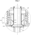
- a butterfly valve 400 according to the fourth example of the present invention will be described based on Fig. 7 , which is an enlarged sectional view of a main part of a butterfly valve according to the fourth example of the present invention.
- the butterfly valve 400 in the fourth example is a butterfly valve in which the shapes of the valve shaft 120 and the bearing unit 140 in the butterfly valve 100 in the first example are modified, and has many components in common with the butterfly valve 100 in the first example. Thus, detailed explanation of common components will be omitted, and only 400-series signs with the same last two digits will be given.
- a sealing bush contact surface 421A of a flange 421 of a valve shaft 420 in the fourth example is inclined in the direction toward the central axis C of the valve shaft 420 and in the direction away from the exhaust pipe EP.
- a valve shaft opposing surface 441B of a sealing bush 441 is also inclined toward the central axis C of the valve shaft 420 in correspondence with the sealing bush contact surface 421A of the valve shaft 420.
- a support bush opposing surface 441C of the sealing bush 441 is inclined in the direction toward the central axis C of the valve shaft 420 and in the direction toward the flange 421 of the valve shaft 420.
- the inclination angle of the valve shaft opposing surface 441B of the sealing bush 441 is equal to the inclination angle of the support bush opposing surface 441C of the sealing bush 441.
- a sealing bush opposing surface 442C of a support bush 442 is also inclined toward the central axis C of the valve shaft 420 in correspondence with the support bush opposing surface 441C of the sealing bush 441.
- the sealing bush contact surface 421A of the valve shaft 420 may be inclined in the direction toward the valve shaft 420 and in the direction approaching to the exhaust pipe EP.
- the support bush opposing surface 441C of the sealing bush 441 may be inclined in the direction toward the central axis C of the valve shaft 420 and in the direction away from the flange 421 of the valve shaft 420.
- the butterfly valve 400 formed in this way in the fourth example has the structure in which the support bush opposing surface 441C of the sealing bush 441 and the sealing bush opposing surface 442C of the support bush 442 are inclined in correspondence with each other. Thereby, since the sealing bush 441 and the support bush 442 can be easily positioned in the radial direction, it is possible to efficiently assemble the bearing unit 440.
- sealing bush contact surface 421A of the valve shaft 420 and the valve shaft opposing surface 441B of the sealing bush 441 are inclined in correspondence with each other.
- the inclination angle of the valve shaft opposing surface 441B of the sealing bush 441 is equal to the inclination angle of the support bush opposing surface 441C of the sealing bush 441.
- a butterfly valve 500 according to the fifth example of the present invention will be described based on Figs. 8A and 8B .
- Fig. 8A is an enlarged sectional view of a main part of a butterfly valve according to the fifth example of the present invention
- Fig. 8B is an enlarged view of part VIIIB in Fig. 8A .
- the butterfly valve 500 in the fifth example is a butterfly valve in which the shape of the bearing unit 140 in the butterfly valve 100 in the first example is modified, and has many components in common with the butterfly valve 100 in the first example. Thus, detailed explanation of common components will be omitted, and only 500-series signs with the same last two digits will be given.
- a support bush 542 is inserted into a sealing bush 541.
- the sealing bush 541 is formed from a cylindrical base 541c and a cylindrical protrusion 541d that protrudes from the base 541c in the axial direction.
- an outer peripheral surface 541d1 of the protrusion 541d is flush with an outer peripheral surface 541c1 of the base 541c.
- an inner diameter ⁇ s1 of the protrusion 541d is larger than the inner diameter cps of the base 541c.
- an axial length Ls1 of the protrusion 541d is longer than the axial length Ls of the base 541c.
- metal aggregate 541a is partially exposed on the inner diameter side as shown in Fig. 8B .
- the support bush 542 inserted into the sealing bush 541 engages with the metal aggregate 541a of the sealing bush 541.
- the support bush 542 is formed from a cylindrical base 542a and a cylindrical protrusion 542b that protrudes from the base 542a in the axial direction.
- An inner peripheral surface 542b1 of the protrusion 542b is flush with an inner peripheral surface 542a1 of the base 542a.
- the inner diameter ⁇ b of the protrusion 542b is equal to the inner diameter of the base 542a and is slightly smaller than the inner diameter cps of the sealing bush 541.
- an outer diameter ⁇ bo1 of the protrusion 542b is smaller than an outer diameter ⁇ bo of the base 542a.
- the outer diameter ⁇ bo1 of the protrusion 542b is approximately equal to the inner diameter ⁇ s1 of the protrusion 541d of the sealing bush 541.
- an axial length Lb1 of the protrusion 542b is longer than the axial length Lb2 of the base 542a.
- the axial length Lb1 of the protrusion 542b is approximately equal to the axial length Ls1 of the protrusion 541d of the sealing bush 541.
- the protrusion 542b of the support bush 542 is located closer to a valve shaft 520 than the protrusion 541d of the sealing bush 541, but the protrusion 541d of the sealing bush 541 may be located closer to the valve shaft 520 than the protrusion 542b of the support bush 542.
- the butterfly valve 500 formed in this way in the fifth example has the structure in which the support bush 542 is inserted into the sealing bush 541. Thereby, since the bearing unit 540 can be easily handled as an integral member, it is possible to efficiently assemble the butterfly valve 500.
- a butterfly valve 600 according to the sixth example of the present invention will be described based on Figs. 9A and 9B .
- Fig. 9A is an exploded perspective view of a bearing unit in a butterfly valve according to the sixth example of the present invention
- Fig. 9B is an enlarged sectional view of a main part of the butterfly valve taken along the IXB-IXB cross section in Fig. 9A .
- the butterfly valve 600 in the sixth example is a butterfly valve in which the shape of the bearing unit 540 in the butterfly valve 500 in the fifth example is modified, and has many components in common with the butterfly valve 500 in the fifth example. Thus, detailed explanation of common components will be omitted, and only 600-series signs with the same last two digits will be given.
- protrusions 641d2 are provided to protrude from the inner peripheral surface of a protrusion 641d of a sealing bush 641.
- the protrusion 641d2 is formed on the sealing bush 641.
- the protrusion 641d2 serves as an insertion guide when inserting the support bush 642 into the sealing bush 641, it is possible to improve the assemblability of a bearing unit 640, and even if the sealing bush 641 is stuck to a flange 621 of the valve shaft 620, since the sealing bush 641 to which the valve shaft 620 is stuck slides relative to the support bush 642, it is possible to maintain the function of the butterfly valve for a long period of time.
- butterfly valves according to the examples of the present invention have been described above, the butterfly valve in the present invention is not limited to the butterfly valves of the examples described above.
- the metal aggregate is woven with stainless steel wires, but the metal aggregate may be woven with any metal wires as long as they are metal wires.
- the metal aggregate is woven with metal wires having the linear expansion coefficient comparable to that of the material of the housing.
- valve plate is provided on the upstream side of the valve shaft.
- the position of the valve plate is not limited to there, and the valve plate may be provided on the downstream side of the valve shaft.
- the support bush is made of stainless steel as the housing is.
- the material of the support bush is not limited to this material, and may be made of, for example, hard carbon or ceramics.
Landscapes
- Engineering & Computer Science (AREA)
- General Engineering & Computer Science (AREA)
- Mechanical Engineering (AREA)
- Chemical & Material Sciences (AREA)
- Combustion & Propulsion (AREA)
- Ceramic Engineering (AREA)
- Control Of Throttle Valves Provided In The Intake System Or In The Exhaust System (AREA)
- Lift Valve (AREA)
- Exhaust Silencers (AREA)
Abstract
Description
- The present invention relates to a butterfly valve, and more particularly, to a butterfly valve that opens and closes an exhaust pipe communicating with an exhaust port of an engine.
- Conventionally, as an exhaust device (butterfly valve) that controls a flow of exhaust gas in an exhaust pipe communicating with an exhaust port of an engine of an automatic two-wheeled vehicle, there is known an exhaust device comprising: a valve body (valve plate) arranged in the exhaust pipe; a valve shaft that is fixed to or integrated with the valve body and is arranged to cross the exhaust pipe; and a pair of bearing members that rotatably support both axial ends of the valve shaft, wherein the valve body is rotated around the valve shaft (for example, in the
patent literature 1.). - [Patent Literature 1]
JP 2008-169797 A Fig. 5 ) - If a butterfly valve as described above is installed in an exhaust pipe communicating with an exhaust port of an engine of an automatic four-wheeled vehicle, since the back pressure will be greater than that in an automatic two-wheeled vehicle, when the valve body closes the exhaust pipe, there is possibility that the bearing member will not be able to withstand a radial load caused by the back pressure.
- Then, if the bearing member is changed to a hard material in order to withstand the back pressure from the engine of the automatic four-wheeled vehicle, there is possibility that the sealing performance of the bearing member will deteriorate so that exhaust gas will leak from the gap between the bearing member and the valve shaft and exhaust soot may accumulate between the bearing member and the valve shaft.
- This problem of accumulation of exhaust soot becomes even more serious in a case where the engine fuel is biodiesel fuel, as exhaust soot is more likely to be generated than in a case where conventional petroleum fuel is used.
- Therefore, the present invention solves the problems of the prior art as described above, and an object of the present invention is to provide a butterfly valve with which the exhaust gas is hard to leak out of the exhaust pipe even under high back pressure.
- The invention according to
claim 1 is a butterfly valve that opens and closes an exhaust pipe communicating with an exhaust port of an engine, comprising: a valve plate provided in the exhaust pipe; a valve shaft that crosses the exhaust pipe and holds the valve plate; a bearing unit that has an annular sealing bush and an annular support bush, which are separate components and into which the valve shaft is inserted, and slidably supports the valve shaft; and a housing that is attached to the exhaust pipe and accommodates the bearing unit arranged outside the exhaust pipe, wherein the support bush of the bearing unit is arranged between the housing and the sealing bush of the bearing unit and is in contact with the housing on an outer peripheral surface of the support bush, and wherein the sealing bush of the bearing unit is in contact with the housing on an outer peripheral surface of the sealing bush and is in contact with a flange of the valve shaft on a valve shaft opposing surface of the sealing bush, and thereby, the problems described above are resolved. - The invention according to claim 2 is that, in addition to the configuration of the butterfly valve according to
claim 1, the sealing bush of the bearing unit is softer than the support bush of the bearing unit, and wherein an inner diameter of the sealing bush is larger than or equal to an inner diameter of the support bush, and thereby, the problems described above are resolved. - The invention according to claim 3 is that, in addition to the configuration of the butterfly valve according to
claim 1 or 2, axial length of the support bush is longer than axial length of the sealing bush, and thereby, the problems described above are resolved. - The invention according to claim 4 is that, in addition to the configuration of the butterfly valve according to any of
claims 1 to 3, the sealing bush is formed from mesh-like metal aggregate woven with metal wires and graphite filled in the metal aggregate, and wherein the metal aggregate is repeatedly bent in the axial direction of the sealing bush, and thereby, the problems described above are resolved. - According to the butterfly valve in the invention according to
claim 1, the sealing bush of the bearing unit is in contact with the housing on an outer peripheral surface of the sealing bush and is in contact with a flange of the valve shaft on a valve shaft opposing surface of the sealing bush. Thereby, since the space between the housing and the bearing unit is sealed and the space between the valve shaft and the bearing unit is also sealed, it is possible to prevent the exhaust gas flowing inside the exhaust pipe from leaking out of the exhaust pipe via the housing. - Further, the support bush of the bearing unit is arranged between the housing and the sealing bush of the bearing unit and is in contact with the housing on an outer peripheral surface of the support bush. Thereby, since the support bush supports the radial load on the valve plate caused by the exhaust gas flowing in the exhaust pipe, even if a high load is applied to the valve plate when the valve plate closes the exhaust pipe, it is possible to prevent deformation, abnormal friction and the like of the sealing bush.
- Therefore, even under high back pressure, it is possible to prevent the exhaust gas from leaking out of the exhaust pipe.
- According to the butterfly valve in the invention according to claim 2, the sealing bush of the bearing unit is softer than the support bush of the bearing unit. Thereby, compared to the case where the sealing bush is harder than the support bush, since the sealing bush easily deforms by following the shape of the housing or the flange of the valve shaft, in addition to the effect of the invention according to
claim 1, it is possible to reliably seal not only between the housing and the bearing unit but also between the valve shaft and the bearing unit. - Further, an inner diameter of the sealing bush is larger than or equal to an inner diameter of the support bush. Thereby, since the valve shaft comes into contact with the inner peripheral surface of the support bush that is harder than the sealing bush before coming into contact with the inner peripheral surface of the sealing bush, even if a high load is applied to the valve plate when the valve plate closes the exhaust pipe, it is possible to reliably support the valve shaft with the support bush.
- Therefore, even under high back pressure, it is possible to reliably prevent the exhaust gas from leaking out of the exhaust pipe.
- According to the butterfly valve in the invention according to claim 3, axial length of the support bush is longer than axial length of the sealing bush. Thereby, compared to the case where the axial length of the support bush is shorter than the axial length of the sealing bush, since the surface pressure applied to the support bush is reduced when a high load is applied to the valve plate in a state where the valve plate closes the exhaust pipe, in addition to the effect of the invention according to
claim 1 or 2, it is possible to further improve the radial load resistance performance of the bearing unit. - According to the butterfly valve in the invention according to claim 4, the sealing bush is formed from mesh-like metal aggregate woven with metal wires and graphite filled in the metal aggregate, and the metal aggregate is repeatedly bent in the axial direction of the sealing bush. Thereby, since the sealing bush expands more easily in the axial direction than in the radial direction and the cushioning properties of the sealing bush in the axial direction are improved, in addition to the effect of the invention according to any of
claims 1 to 3, it is possible to further improve the sealing performance between the sealing bush and the flange of the valve shaft. -
-
Fig. 1 is a perspective view of an exhaust pipe incorporating a butterfly valve according to the first example of the present invention. -
Fig. 2 is a longitudinal cross-sectional view ofFig. 1 . -
Fig. 3 is an enlarged view of part III inFig. 2 . -
Fig. 4 is an enlarged view of part IV inFig. 3 . -
Fig. 5 is an enlarged sectional view of a main part of a butterfly valve according to the second example of the present invention. -
Fig. 6 is an enlarged sectional view of a main part of a butterfly valve according to the third example of the present invention. -
Fig. 7 is an enlarged sectional view of a main part of a butterfly valve according to the fourth example of the present invention. -
Fig. 8A is an enlarged sectional view of a main part of a butterfly valve according to the fifth example of the present invention. -
Fig. 8B is an enlarged view of part VIIIB inFig. 8A . -
Fig. 9A is an exploded perspective view of a bearing unit in a butterfly valve according to the sixth example of the present invention. -
Fig. 9B is an enlarged sectional view of a main part of the butterfly valve taken along the IXB-IXB cross section inFig. 9A . - The specific embodiment of a butterfly valve in the present invention may be arbitrary as long as a butterfly valve that opens and closes an exhaust pipe communicating with an exhaust port of an engine comprises: a valve plate provided in the exhaust pipe; a valve shaft that crosses the exhaust pipe and holds the valve plate; a bearing unit that has an annular sealing bush and an annular support bush, which are separate components and into which the valve shaft is inserted, and slidably supports the valve shaft; and a housing that is attached to the exhaust pipe and accommodates the bearing unit arranged outside the exhaust pipe, wherein the support bush of the bearing unit is arranged between the housing and the sealing bush of the bearing unit and is in contact with the housing on an outer peripheral surface of the support bush, and wherein the sealing bush of the bearing unit is in contact with the housing on an outer peripheral surface of the sealing bush and is in contact with a flange of the valve shaft on a valve shaft opposing surface of the sealing bush, and thereby, with this butterfly valve, exhaust gas is hard to leak out of the exhaust pipe even under high back pressure.
- For example, the butterfly valve in the present invention is provided in an exhaust pipe communicating with the exhaust port of an engine of an automatic four-wheeled vehicle. However, the butterfly valve of the present invention may be provided not only in an automatic four-wheeled vehicle but also in an automatic two-wheeled vehicle, and the automatic four-wheeled vehicle may be a gasoline vehicle or a diesel vehicle.
- That is, the engine with which the exhaust pipe communicates may be a gasoline engine or a diesel engine.
- Here, diesel engines used in trucks generally have higher back pressure than gasoline engines used in passenger cars. However, the butterfly valve according to the present invention can sufficiently suppress leakage of exhaust gas out of the exhaust pipe.
- Hereinafter, a
butterfly valve 100 according to the first example of the present invention will be described below based onFigs. 1 to 4 . - First, the environment in which the
butterfly valve 100 is installed will be described based onFig. 1 , which is a perspective view of an exhaust pipe incorporating a butterfly valve according to the first example of the present invention. - The
butterfly valve 100 of the present example opens and closes an exhaust pipe EP communicating with an exhaust port (not shown) of a diesel engine of an automatic four-wheeled vehicle, and is arranged in the middle of the cylindrical exhaust pipe EP as shown inFig. 1 . - Next, the structure of the
butterfly valve 100 will be described based onFigs. 1 to 4 . -
Fig. 2 is a longitudinal cross-sectional view ofFig. 1 ,Fig. 3 is an enlarged view of part III inFig. 2 , andFig. 4 is an enlarged view of part IV inFig. 3 . - As shown in
Figs. 1 and2 , thebutterfly valve 100 includes a disk-shapedvalve plate 110 provided in the exhaust pipe EP, avalve shaft 120 that crosses the exhaust pipe EP and holds thevalve plate 110, a connectingbolt 130 that connects thevalve plate 110 and thevalve shaft 120, abearing unit 140 that slidably supports thevalve shaft 120, and ahousing 150 that is attached to the exhaust pipe E and accommodates thebearing unit 140 arranged outside the exhaust pipe EP. - The
valve plate 110 is provided on the upstream side of thevalve shaft 120, as shown inFig. 2 . - Thereby, even if the back pressure of exhaust gas EG is applied to the
valve plate 110, thevalve plate 110 is pressed against thevalve shaft 120, so that thevalve plate 110 is hard to detach from thevalve shaft 120. - As shown in
Fig. 2 ,flanges 121 are formed at both ends of thevalve shaft 120 and protrude in the radial direction. - As shown in
Fig. 3 , a diameter cpF of theflange 121 is smaller than a diameter cpP of a shaft insertion hole EP1 formed in the exhaust pipe EP. - Further, as shown in
Fig. 3 , the diameter of thevalve shaft 120 outward from theflange 121 is constant up to the end. - Furthermore, a male thread is formed at one end (upper end in
Fig. 2 ) of thevalve shaft 120. - As shown in
Fig. 2 , thebearing unit 140 consists of anannular sealing bush 141 and anannular support bush 142, into which thevalve shaft 120 is inserted. - As shown in
Figs. 2 and3 , the sealingbush 141 is a separate component from thesupport bush 142 and is softer than the support bush 142 (for example, the Young's modulus of the sealingbush 141 is 0.15 to 0.5 GPa or more, Poisson's ratio is approximately 0.2 to 0.3, and compressive strength is 46 MPa or less). - The sealing
bush 141 is in pressure contact with thehousing 150 on an outerperipheral surface 141A and is in contact with theflange 121 of thevalve shaft 120 on a valveshaft opposing surface 141B. - Therefore, the space between the sealing
bush 141 and thehousing 150 is sealed, and the space between the sealingbush 141 and theflange 121 of thevalve shaft 120 is also sealed. - Further, an inner diameter cps of the sealing
bush 141 is slightly larger than an inner diameter cpb of thesupport bush 142. - Here, the inner diameter cps of the sealing
bush 141 may be equal to the inner diameter cpb of thesupport bush 142. - As shown in
Fig. 4 , the sealingbush 141 is formed from mesh-like metal aggregate 141a woven with metal wires (stainless wires in the present example) andgraphite 141b filled in themetal aggregate 141a. - The
metal aggregate 141a is repeatedly bent in the axial direction of the sealing bush 141 (that is, the direction in which thevalve shaft 120 extends; the upper-lower direction inFig. 4 ). - Therefore, the
metal aggregate 141a easily expands in the axial direction. - The
graphite 141b is expanded graphite in order to easily enter gaps in themetal aggregate 141a. - In the present example, the
support bush 142 is made of stainless steel as thehousing 150 is, and has substantially the same linear expansion coefficient as thehousing 150. - Thereby, when the
butterfly valve 100 becomes high temperature due to exhaust gas or the like, thesupport bush 142 also expands as well as thehousing 150, so that the space between thesupport bush 142 and thehousing 150 can be kept sealed. - As shown in
Figs. 2 and3 , thesupport bush 142 is arranged between thehousing 150 and the sealingbush 141 and is in pressure contact with thehousing 150 on an outerperipheral surface 142A. - Further, an axial length Lb of the
support bush 142 is longer than an axial length Ls of the sealingbush 141. - The
housing 150 is a component that covers the shaft insertion hole EP1 of the exhaust pipe EP, and as shown inFig. 2 , consists of a cylindrical fixedside housing 151 with a flange and a bottom, which is attached to the lower side of the exhaust pipe EP, and a cylindricaldetachable side housing 152 with a flange and a bottom, which is attached to the upper side of the exhaust pipe EP. - The fixed
side housing 151 is integrated with the exhaust pipe EP by welding or the like so that the exhaust gas EG does not leak from the space between the fixedside housing 151 and the exhaust pipe EP. - The
detachable side housing 152 is in contact with the exhaust pipe EP, and as shown inFig. 3 , a throughhole 152a through which thevalve shaft 120 is inserted is formed in the bottom surface. - As shown in
Fig. 3 , a diameter cph of the throughhole 152a is slightly larger than a diameter cpd of thevalve shaft 120. - Further, as shown in
Fig. 3 , the inner diameter of the housing 150 (that is, the inner diameter of the fixedside housing 151 and the inner diameter of the detachable side housing 152) ϕi is slightly larger than the diameter cpF of theflange 121 of thevalve shaft 120 and is smaller than the diameter ϕP of the shaft insertion hole EP1 of the exhaust pipe EP. - Further, the
butterfly valve 100 includes a coiledpressing spring 160 that presses thedetachable side housing 152 against the exhaust pipe EP, and a valveshaft rotation mechanism 170 that rotates thevalve shaft 120. - As shown in
Fig. 2 , thepressing spring 160 is a torsion coil spring, is arranged between thedetachable side housing 152 and the valveshaft rotation mechanism 170, and biases thedetachable side housing 152 toward the exhaust pipe EP. - Due to this
pressing spring 160, thedetachable side housing 152 is in contact with the exhaust pipe EP so that the exhaust gas EG does not leak from the space between thedetachable side housing 152 and the exhaust pipe EP. - As shown in
Fig. 1 , the valveshaft rotation mechanism 170 includes an annularrotary plate 171 that is in contact with the other end of thepressing spring 160, a fixingnut 172 that fixes therotary plate 171 to thevalve shaft 120, and astopper 173 that bends up from the exhaust pipe EP and stops rotation of therotary plate 171 and a valve shaft drive actuator (not shown) that rotates thevalve shaft 120. - Here, when the
valve plate 110 closes the exhaust pipe EP as shown inFig. 1 , thepressing spring 160 is being twisted by the valve shaft drive actuator. - In other words, when the
pressing spring 160 is not twisted, that is, when the valve shaft drive actuator is not operating, thevalve plate 110 does not close the exhaust pipe EP, and the exhaust gas EG can freely flow through the exhaust pipe EP. - The
rotary plate 171 rotates together with thevalve shaft 120, and as shown inFig.1 , includes aspring suppressing portion 171a, which bends down from therotary plate 171 and is in contact with a tip portion on one end side of thepressing spring 160, and twoarm portions 171b that come into contact with thestopper 173. - The
spring suppressing portion 171a is L-shaped, and is in contact with the tip portion of one end of thepressing spring 160 on two sides. - The
arm portion 171b is formed of a horizontal portion that extends in the horizontal direction and a bending-down portion that bends down from the tip of the horizontal portion and comes into contact with thestopper 173. - Here, since the two
arm portions 171b are formed, the valve shaft 120 (that is, the valve plate 110) is rotatable within an angular range between the twoarm portions 171b. - A female thread is formed on the inner surface of the fixing
nut 172 and is screwed by a male thread formed on thevalve shaft 120. - Thereby, by screwing the fixing
nut 172 onto thevalve shaft 120 in a state where thevalve shaft 120 is inserted into therotary plate 171, thepressing spring 160 is compressed and thedetachable side housing 152 is pressed against the exhaust pipe EP. - As shown in
Fig. 1 , thestopper 173 is in contact with not only thearm portion 171b of therotary plate 171 but also the tip portion of the other end of thepressing spring 160. - According to the
butterfly valve 100 of the present example described above, the sealingbush 141, which is a separate component from thesupport bush 142 of thebearing unit 140, is contact with the housing 150 (fixedside housing 151, detachable side housing 152) on the outerperipheral surface 141A of the sealingbush 141 and is in contact with theflange 121 of thevalve shaft 120 at the valveshaft opposing surface 141B of the sealingbush 141. Thereby, since the space between thehousing 150 and thebearing unit 140 is sealed and the space between thevalve shaft 120 and thebearing unit 140 is also sealed, it is possible to prevent the exhaust gas EG flowing inside the exhaust pipe EP from leaking out of the exhaust pipe EP via thehousing 150. - Further, the
support bush 142 of thebearing unit 140 is arranged between thehousing 150 and the sealingbush 141 of thebearing unit 140 and is in contact with thehousing 150 on the outerperipheral surface 142A of thesupport bush 142. Thereby, since thesupport bush 142 supports the radial load on thevalve plate 110 caused by the exhaust gas EG flowing in the exhaust pipe EP, even if a high load is applied to thevalve plate 110 when thevalve plate 110 closes the exhaust pipe EP, it is possible to prevent deformation, abnormal friction and the like of the sealingbush 141. - Therefore, even under high back pressure, it is possible to prevent the exhaust gas EG from leaking out of the exhaust pipe EP.
- That is, although there is generally a trade-off relationship between load-bearing performance and sealing performance, by adopting the configuration in which the
bearing unit 140 is consisted of two components as in thebutterfly valve 100 of the present example, load-bearing performance and sealing performance can be both achieved. - Further, even if the sealing
bush 141 and theflange 121 of thevalve shaft 120 are stuck together due to rust or the like, since the outerperipheral surface 141A of the sealingbush 141 and thehousing 150 slide while the sealingbush 141 and thesupport bush 142 slide, this butterfly valve can continue to function. - Further, the sealing
bush 141 seals the space between the exhaust pipe EP and thehousing 150. Thereby, since condensed water in the exhaust pipe EP is less likely to enter thesupport bush 142, thesupport bush 142 is less likely to rust. - Further, the sealing
bush 141 of thebearing unit 140 is softer than thesupport bush 142 of thebearing unit 140. Thereby, compared to the case where the sealingbush 141 is harder than thesupport bush 142, the sealingbush 141 easily deforms by following the shape of thehousing 150 or theflange 121 of thevalve shaft 120. - Further, the inner diameter cps of the sealing
bush 141 is larger than or equal to the inner diameter cpb of thesupport bush 142. Thereby, thevalve shaft 120 comes into contact with the inner peripheral surface of thesupport bush 142 that is harder than the sealingbush 141 before coming into contact with the inner peripheral surface of the sealingbush 141. - Therefore, even under high back pressure, it is possible to reliably prevent the exhaust gas EG from leaking out of the exhaust pipe EP.
- Further, the axial length Lb of the
support bush 142 is longer than the axial length Ls of the sealingbush 141. Thereby, compared to the case where the axial length Lb of thesupport bush 142 is shorter than the axial length Ls of the sealingbush 141, since the surface pressure applied to thesupport bush 142 is reduced when a high load is applied to thevalve plate 110 in a state where thevalve plate 110 closes the exhaust pipe EP, it is possible to further improve the radial load resistance performance of thebearing unit 140. - Further, the sealing
bush 141 is formed from the mesh-like metal aggregate 141a woven with metal wires (stainless steel wires) and thegraphite 141b filled in themetal aggregate 141a, and themetal aggregate 141a is repeatedly bent in the axial direction of the sealingbush 141. Thereby, since the sealingbush 141 expands more easily in the axial direction than in the radial direction and the cushioning properties of the sealingbush 141 in the axial direction are improved, it is possible to further improve the sealing performance between the sealingbush 141 and theflange 121 of thevalve shaft 120. - Further, as shown in
Fig. 4 , thegraphite 141b, which has a smaller friction coefficient than themetal aggregate 141a, is exposed on the surface of the sealingbush 141. Thereby, the torque for rotating thevalve shaft 120 is reduced, and it is possible to downsize the shaft drive actuator. - Further, the
metal aggregate 141a is woven with stainless steel wires. Thereby, since the sealingbush 141 has cushioning properties, the sealingbush 141 is less likely to be shaved when the sealingbush 141 is press-fitted into thehousing 150, and even if thevalve shaft 120 is slightly tilted, thevalve shaft 120 can be stably supported and vertical vibrations can be absorbed when the automatic four-wheeled vehicle is running. - Next, a
butterfly valve 200 according to the second example of the present invention will be described based onFig. 5 , which is an enlarged sectional view of a main part of a butterfly valve according to the second example of the present invention. - Here, the
butterfly valve 200 in the second example is a butterfly valve in which the shape of thebearing unit 140 in thebutterfly valve 100 in the first example is modified, and has many components in common with thebutterfly valve 100 in the first example. Thus, detailed explanation of common components will be omitted, and only 200-series signs with the same last two digits will be given. - As shown in
Fig. 5 , in abearing unit 240 in the second example, a supportbush opposing surface 241C of a sealingbush 241 is inclined in the direction toward a central axis C of avalve shaft 220 and in the direction toward aflange 221 of thevalve shaft 220. - Here, the support
bush opposing surface 241C may be inclined in the direction toward the central axis C of thevalve shaft 220 and in the direction away from theflange 221 of thevalve shaft 220. - A sealing
bush opposing surface 242C of asupport bush 242 is also inclined toward the central axis C of thevalve shaft 220 in correspondence with the supportbush opposing surface 241C of the sealingbush 241. - The
butterfly valve 200 formed in this way in the second example has the structure in which the supportbush opposing surface 241C of the sealingbush 241 and the sealingbush opposing surface 242C of thesupport bush 242 are inclined in correspondence with each other. Thereby, since the sealingbush 241 and thesupport bush 242 can be easily positioned in the radial direction, it is possible to efficiently assemble thebearing unit 240. - Next, a
butterfly valve 300 according to the third example of the present invention will be described based onFig. 6 , which is an enlarged sectional view of a main part of a butterfly valve according to the third example of the present invention. - Here, the
butterfly valve 300 in the third example is a butterfly valve in which the shapes of thevalve shaft 120 and thebearing unit 140 in thebutterfly valve 100 in the first example are modified, and has many components in common with thebutterfly valve 100 in the first example. Thus, detailed explanation of common components will be omitted, and only 300-series signs with the same last two digits will be given. - As shown in
Fig. 6 , a sealingbush contact surface 321A of aflange 321 of avalve shaft 320 in the third example is inclined in the direction toward the central axis C of thevalve shaft 320 and in the direction away from the exhaust pipe EP. - Here, the sealing
bush contact surface 321A may be inclined in the direction toward thevalve shaft 320 and in the direction approaching to the exhaust pipe EP. - A valve
shaft opposing surface 341B of a sealingbush 341 is also inclined toward the central axis C of thevalve shaft 320 in correspondence with the sealingbush contact surface 321A of thevalve shaft 320. - The
butterfly valve 300 formed in this way in the third example has the structure in which the sealingbush contact surface 321A of thevalve shaft 320 and the valveshaft opposing surface 341B of the sealingbush 341 are inclined in correspondence with each other. Thereby, since thevalve shaft 320 is positioned relative to abearing unit 340, it is possible to reliably seal the space between thevalve shaft 320 and thebearing unit 340 and reliably support thevalve shaft 320. - Next, a
butterfly valve 400 according to the fourth example of the present invention will be described based onFig. 7 , which is an enlarged sectional view of a main part of a butterfly valve according to the fourth example of the present invention. - Here, the
butterfly valve 400 in the fourth example is a butterfly valve in which the shapes of thevalve shaft 120 and thebearing unit 140 in thebutterfly valve 100 in the first example are modified, and has many components in common with thebutterfly valve 100 in the first example. Thus, detailed explanation of common components will be omitted, and only 400-series signs with the same last two digits will be given. - As shown in
Fig. 7 , a sealingbush contact surface 421A of aflange 421 of avalve shaft 420 in the fourth example is inclined in the direction toward the central axis C of thevalve shaft 420 and in the direction away from the exhaust pipe EP. - A valve
shaft opposing surface 441B of a sealingbush 441 is also inclined toward the central axis C of thevalve shaft 420 in correspondence with the sealingbush contact surface 421A of thevalve shaft 420. - Further, a support bush opposing surface 441C of the sealing
bush 441 is inclined in the direction toward the central axis C of thevalve shaft 420 and in the direction toward theflange 421 of thevalve shaft 420. - Here, the inclination angle of the valve
shaft opposing surface 441B of the sealingbush 441 is equal to the inclination angle of the support bush opposing surface 441C of the sealingbush 441. - A sealing
bush opposing surface 442C of asupport bush 442 is also inclined toward the central axis C of thevalve shaft 420 in correspondence with the support bush opposing surface 441C of the sealingbush 441. - Here, the sealing
bush contact surface 421A of thevalve shaft 420 may be inclined in the direction toward thevalve shaft 420 and in the direction approaching to the exhaust pipe EP. - Further, the support bush opposing surface 441C of the sealing
bush 441 may be inclined in the direction toward the central axis C of thevalve shaft 420 and in the direction away from theflange 421 of thevalve shaft 420. - The
butterfly valve 400 formed in this way in the fourth example has the structure in which the support bush opposing surface 441C of the sealingbush 441 and the sealingbush opposing surface 442C of thesupport bush 442 are inclined in correspondence with each other. Thereby, since the sealingbush 441 and thesupport bush 442 can be easily positioned in the radial direction, it is possible to efficiently assemble thebearing unit 440. - Further, the sealing
bush contact surface 421A of thevalve shaft 420 and the valveshaft opposing surface 441B of the sealingbush 441 are inclined in correspondence with each other. Thereby, since thevalve shaft 420 is positioned relative to abearing unit 440, it is possible to reliably seal the space between thevalve shaft 420 and thebearing unit 440 and reliably support thevalve shaft 420. - Further, the inclination angle of the valve
shaft opposing surface 441B of the sealingbush 441 is equal to the inclination angle of the support bush opposing surface 441C of the sealingbush 441. Thereby, since the axial directionality of the sealingbush 441 is eliminated, it is possible to suppress incorrect assembly of the sealingbush 441. - Next, a
butterfly valve 500 according to the fifth example of the present invention will be described based onFigs. 8A and 8B . -
Fig. 8A is an enlarged sectional view of a main part of a butterfly valve according to the fifth example of the present invention, andFig. 8B is an enlarged view of part VIIIB inFig. 8A . - Here, the
butterfly valve 500 in the fifth example is a butterfly valve in which the shape of thebearing unit 140 in thebutterfly valve 100 in the first example is modified, and has many components in common with thebutterfly valve 100 in the first example. Thus, detailed explanation of common components will be omitted, and only 500-series signs with the same last two digits will be given. - As shown in
Fig. 8A , in abearing unit 540 in the fifth example, asupport bush 542 is inserted into a sealingbush 541. - The sealing
bush 541 is formed from acylindrical base 541c and acylindrical protrusion 541d that protrudes from thebase 541c in the axial direction. - As shown in
Fig. 8A , an outer peripheral surface 541d1 of theprotrusion 541d is flush with an outer peripheral surface 541c1 of thebase 541c. - Further, as shown in
Fig. 8A , an inner diameter ϕs1 of theprotrusion 541d is larger than the inner diameter cps of thebase 541c. - Further, as shown in
Fig. 8A , an axial length Ls1 of theprotrusion 541d is longer than the axial length Ls of thebase 541c. - Further, in the sealing
bush 541 in the present example,metal aggregate 541a is partially exposed on the inner diameter side as shown inFig. 8B . - Therefore, the
support bush 542 inserted into the sealingbush 541 engages with themetal aggregate 541a of the sealingbush 541. - The
support bush 542 is formed from acylindrical base 542a and acylindrical protrusion 542b that protrudes from thebase 542a in the axial direction. - An inner peripheral surface 542b1 of the
protrusion 542b is flush with an inner peripheral surface 542a1 of thebase 542a. - That is, as shown in
Fig. 8A , the inner diameter ϕb of theprotrusion 542b is equal to the inner diameter of thebase 542a and is slightly smaller than the inner diameter cps of the sealingbush 541. - As shown in
Fig. 8A , an outer diameter ϕbo1 of theprotrusion 542b is smaller than an outer diameter ϕbo of thebase 542a. - Further, as shown in
Fig. 8A , the outer diameter ϕbo1 of theprotrusion 542b is approximately equal to the inner diameter ϕs1 of theprotrusion 541d of the sealingbush 541. - As shown in
Fig. 8A , an axial length Lb1 of theprotrusion 542b is longer than the axial length Lb2 of thebase 542a. - Further, as shown in
Fig. 8A , the axial length Lb1 of theprotrusion 542b is approximately equal to the axial length Ls1 of theprotrusion 541d of the sealingbush 541. - In the present example, the
protrusion 542b of thesupport bush 542 is located closer to avalve shaft 520 than theprotrusion 541d of the sealingbush 541, but theprotrusion 541d of the sealingbush 541 may be located closer to thevalve shaft 520 than theprotrusion 542b of thesupport bush 542. - The
butterfly valve 500 formed in this way in the fifth example has the structure in which thesupport bush 542 is inserted into the sealingbush 541. Thereby, since thebearing unit 540 can be easily handled as an integral member, it is possible to efficiently assemble thebutterfly valve 500. - Next, a
butterfly valve 600 according to the sixth example of the present invention will be described based onFigs. 9A and 9B . -
Fig. 9A is an exploded perspective view of a bearing unit in a butterfly valve according to the sixth example of the present invention, andFig. 9B is an enlarged sectional view of a main part of the butterfly valve taken along the IXB-IXB cross section inFig. 9A . - Here, the
butterfly valve 600 in the sixth example is a butterfly valve in which the shape of thebearing unit 540 in thebutterfly valve 500 in the fifth example is modified, and has many components in common with thebutterfly valve 500 in the fifth example. Thus, detailed explanation of common components will be omitted, and only 600-series signs with the same last two digits will be given. - As shown in
Fig. 9A , in abearing unit 640 in the sixth example, protrusions 641d2 are provided to protrude from the inner peripheral surface of aprotrusion 641d of a sealingbush 641. - When inserting a
support bush 642 into the sealingbush 641, since the sealingbush 641 is softer than thesupport bush 642, as shown inFig. 9B , the protrusion 641d2 of the sealingbush 641 is crushed, and thesupport bush 642 comes into contact with a part of the sealingbush 641. - In the
butterfly valve 600 formed in this way in the sixth example, the protrusion 641d2 is formed on the sealingbush 641. Thereby, since the protrusion 641d2 serves as an insertion guide when inserting thesupport bush 642 into the sealingbush 641, it is possible to improve the assemblability of abearing unit 640, and even if the sealingbush 641 is stuck to aflange 621 of thevalve shaft 620, since the sealingbush 641 to which thevalve shaft 620 is stuck slides relative to thesupport bush 642, it is possible to maintain the function of the butterfly valve for a long period of time. - Although the butterfly valves according to the examples of the present invention have been described above, the butterfly valve in the present invention is not limited to the butterfly valves of the examples described above.
- For example, in the examples described above, the metal aggregate is woven with stainless steel wires, but the metal aggregate may be woven with any metal wires as long as they are metal wires. However, in order to reliably seal the space between the housing and the sealing bush, it is preferable that the metal aggregate is woven with metal wires having the linear expansion coefficient comparable to that of the material of the housing.
- For example, in the examples described above, the valve plate is provided on the upstream side of the valve shaft. However, the position of the valve plate is not limited to there, and the valve plate may be provided on the downstream side of the valve shaft.
- For example, in the examples described above, the support bush is made of stainless steel as the housing is. However, the material of the support bush is not limited to this material, and may be made of, for example, hard carbon or ceramics.
-
- 100, 200, 300, 400, 500, 600
- butterfly valve
- 110
- valve plate
- 120, 220, 320, 420, 520
- valve shaft
- 121, 321, 421
- flange
- 321A, 421A
- sealing bush contact surface
- 130
- connecting bolt
- 140, 240, 340, 440, 540
- bearing unit
- 141, 241, 341, 441, 541, 641
- sealing bush
- 141A
- outer peripheral surface
- 141B, 341B, 441B
- valve shaft opposing surface
- 241C, 441C
- support bush opposing surface
- 141a, 541a
- metal aggregate
- 141b, 541b
- graphite
- 541c
- base
- 541c1
- outer peripheral surface
- 541d, 641d
- protrusion
- 541d1
- outer peripheral surface
- 641d2
- protrusion
- 142, 242, 342, 442, 542, 642
- support bush
- 142A
- outer peripheral surface
- 242C, 442C
- sealing bush opposing surface
- 542a
- base
- 542a1
- inner peripheral surface
- 542b
- protrusion
- 542b1
- inner peripheral surface
- 150
- housing
- 151
- fixed side housing
- 152
- detachable side housing
- 160
- pressing spring
- 170
- valve shaft rotation mechanism
- 171
- rotary plate
- 171a
- spring suppressing portion
- 171b
- arm portion
- 172
- fixing nut
- 173
- stopper
- EP1
- shaft insertion hole
- EP
- exhaust pipe
- EG
- exhaust gas
- C
- central axis of valve shaft
- cpF
- diameter of flange
- ϕi
- inner diameter of housing
- ϕP
- diameter of shaft insertion hole of exhaust
- pipe cps
- inner diameter of sealing bush (base)
- ϕs1
- inner diameter of protrusion of sealing bush
- cpb
- inner diameter of support bush (protrusion)
- ϕbo
- outer diameter of support bush (base)
- ϕbo1
- outer diameter of protrusion of support bush
- cph
- diameter of through hole of detachable side
- housing ϕd
- diameter of valve shaft
- Ls
- axial length of sealing bush (base)
- Ls1
- axial length of sealing bush (protrusion)
- Lb
- axial length of support bush
- Lb1
- axial length of sealing bush (protrusion)
- Ls2
- axial length of sealing bush (base)
Claims (4)
- A butterfly valve that opens and closes an exhaust pipe communicating with an exhaust port of an engine, comprising:a valve plate provided in the exhaust pipe;a valve shaft that crosses the exhaust pipe and holds the valve plate;a bearing unit that has an annular sealing bush and an annular support bush, which are separate components and into which the valve shaft is inserted, and slidably supports the valve shaft; anda housing that is attached to the exhaust pipe and accommodates the bearing unit arranged outside the exhaust pipe, whereinthe support bush of the bearing unit is arranged between the housing and the sealing bush of the bearing unit and is in contact with the housing on an outer peripheral surface of the support bush, and whereinthe sealing bush of the bearing unit is in contact with the housing on an outer peripheral surface of the sealing bush and is in contact with a flange of the valve shaft on a valve shaft opposing surface of the sealing bush.
- The butterfly valve according to claim 1, wherein the sealing bush of the bearing unit is softer than the support bush of the bearing unit, and wherein
an inner diameter of the sealing bush is larger than or equal to an inner diameter of the support bush. - The butterfly valve according to claim 1 or 2, wherein axial length of the support bush is longer than axial length of the sealing bush.
- The butterfly valve according to any of claims 1 to 3, wherein the sealing bush is formed from mesh-like metal aggregate woven with metal wires and graphite filled in the metal aggregate, and wherein
the metal aggregate is repeatedly bent in the axial direction of the sealing bush.
Applications Claiming Priority (2)
| Application Number | Priority Date | Filing Date | Title |
|---|---|---|---|
| JP2022011067A JP7083432B1 (en) | 2022-01-27 | 2022-01-27 | Butterfly valve |
| PCT/JP2023/001584 WO2023145614A1 (en) | 2022-01-27 | 2023-01-19 | Butterfly valve |
Publications (3)
| Publication Number | Publication Date |
|---|---|
| EP4446572A1 true EP4446572A1 (en) | 2024-10-16 |
| EP4446572A9 EP4446572A9 (en) | 2024-12-18 |
| EP4446572A4 EP4446572A4 (en) | 2025-12-03 |
Family
ID=81972123
Family Applications (1)
| Application Number | Title | Priority Date | Filing Date |
|---|---|---|---|
| EP23746827.7A Pending EP4446572A4 (en) | 2022-01-27 | 2023-01-19 | FLAP VALVE |
Country Status (5)
| Country | Link |
|---|---|
| US (1) | US20250101924A1 (en) |
| EP (1) | EP4446572A4 (en) |
| JP (1) | JP7083432B1 (en) |
| CN (1) | CN118510985A (en) |
| WO (1) | WO2023145614A1 (en) |
Families Citing this family (1)
| Publication number | Priority date | Publication date | Assignee | Title |
|---|---|---|---|---|
| JP7577175B1 (en) | 2023-08-30 | 2024-11-01 | 三恵技研工業株式会社 | Exhaust valves and mufflers for automobiles |
Family Cites Families (21)
| Publication number | Priority date | Publication date | Assignee | Title |
|---|---|---|---|---|
| JPS5129263B2 (en) * | 1972-09-19 | 1976-08-24 | ||
| JPS54122209U (en) * | 1978-02-16 | 1979-08-27 | ||
| JPS54168424U (en) * | 1978-05-18 | 1979-11-28 | ||
| FR2455699B1 (en) * | 1979-05-04 | 1985-10-25 | Gachot Jean | BUTTERFLY VALVE AND MANUFACTURING METHOD THEREFOR |
| JPH0128371Y2 (en) * | 1984-10-31 | 1989-08-29 | ||
| US5018548A (en) * | 1990-01-12 | 1991-05-28 | Victaulic Company Of America | Segmented coupling for pipes |
| JPH07208217A (en) * | 1994-01-20 | 1995-08-08 | Fuji Oozx Inc | Exhaust brake butterfly valve device |
| US6016826A (en) * | 1995-09-26 | 2000-01-25 | M&Fc Holding Company, Inc. | Automatic center cavity equalizing valve |
| JPH1047489A (en) * | 1996-07-30 | 1998-02-20 | Nippon Leakless Corp | Soft seal ring |
| US6111928A (en) * | 1997-09-29 | 2000-08-29 | Combustion Engineering, Inc. | Top mount canopy seal clamp assembly |
| DE10329336A1 (en) * | 2003-06-30 | 2005-01-20 | Friedrich Boysen Gmbh & Co. Kg | flap valve |
| DE102004032856A1 (en) * | 2004-07-07 | 2006-02-02 | Faurecia Abgastechnik Gmbh | Flap valve for the exhaust system of a motor vehicle |
| JP4842203B2 (en) * | 2007-05-07 | 2011-12-21 | 株式会社ミクニ | Exhaust valve seal structure |
| DE102009052423B4 (en) * | 2009-11-10 | 2011-07-28 | Heinrich Gillet GmbH, 67480 | Valve assembly |
| DE102011089080B4 (en) * | 2011-12-19 | 2013-10-10 | Continental Automotive Gmbh | valve device |
| DE102012103926B4 (en) * | 2012-05-04 | 2015-01-08 | Pierburg Gmbh | Valve bearing system for a flap shaft in a motor vehicle |
| JP2015169280A (en) * | 2014-03-07 | 2015-09-28 | 大豊工業株式会社 | Valve assembly |
| CN110621859B (en) * | 2017-03-20 | 2022-04-05 | 富尔西亚排气系统公司 | Valve with heat-insulating coupling and exhaust line with such a valve |
| CN210769043U (en) * | 2017-04-11 | 2020-06-16 | 富尔西亚排气系统公司 | Valve and exhaust gas line having such valve |
| JP7127560B2 (en) * | 2019-01-30 | 2022-08-30 | 株式会社デンソー | butterfly valve |
| DE102020103420A1 (en) * | 2020-02-11 | 2021-08-12 | Friedrich Boysen GmbH & Co KG. | Flap device |
-
2022
- 2022-01-27 JP JP2022011067A patent/JP7083432B1/en active Active
-
2023
- 2023-01-19 WO PCT/JP2023/001584 patent/WO2023145614A1/en not_active Ceased
- 2023-01-19 EP EP23746827.7A patent/EP4446572A4/en active Pending
- 2023-01-19 US US18/728,215 patent/US20250101924A1/en active Pending
- 2023-01-19 CN CN202380016037.0A patent/CN118510985A/en active Pending
Also Published As
| Publication number | Publication date |
|---|---|
| JP7083432B1 (en) | 2022-06-10 |
| CN118510985A (en) | 2024-08-16 |
| WO2023145614A1 (en) | 2023-08-03 |
| JP2023109667A (en) | 2023-08-08 |
| EP4446572A9 (en) | 2024-12-18 |
| EP4446572A4 (en) | 2025-12-03 |
| US20250101924A1 (en) | 2025-03-27 |
| JP2023109514A (en) | 2023-08-08 |
Similar Documents
| Publication | Publication Date | Title |
|---|---|---|
| US8469336B2 (en) | Valve assembly | |
| EP2706273B1 (en) | Lip type seal | |
| JP5345708B2 (en) | Valve shaft leakage reduction structure | |
| CN101646888B (en) | Exhaust valve with multifunctional spring | |
| EP4446572A1 (en) | Butterfly valve | |
| CN102207017A (en) | Exhaust gas pipe for a motor vehicle and exhaust gas unit | |
| CN108027072B (en) | Valve seat ring for butterfly valve, fixing structure thereof, and eccentric butterfly valve | |
| CN101558223B (en) | Clamping flange arrangement for connecting an exhaust system to an internal combustion engine | |
| CN109312669B (en) | Exhaust gas flap arrangement for an internal combustion engine | |
| KR101306828B1 (en) | Lip type seal | |
| US5865422A (en) | Bi-directional valve seal mechanism | |
| CN115854060A (en) | High-performance metal sealing ball valve | |
| CN109707502A (en) | Turbocharger Turbo Wastegate Assembly | |
| JP7854858B2 (en) | Butterfly valve | |
| JPH11148563A (en) | Eccentric valve | |
| US20210222775A1 (en) | Component Assembly for a Motor Vehicle | |
| JP4933333B2 (en) | Eccentric butterfly valve | |
| WO2013008268A1 (en) | Shaft seal structure for valve | |
| CN208519218U (en) | Ball valve | |
| EP1391609A1 (en) | Metering device with hydraulic bushing element | |
| Hansmann | Mechanical seal with compact external quench supply | |
| JP2000035144A (en) | Injectable seat structure | |
| WO2025143200A1 (en) | Lining-type butterfly valve and manufacturing method thereof | |
| CN121719930A (en) | Butterfly valve sealing element | |
| JP2005170105A (en) | Fuel check-valve |
Legal Events
| Date | Code | Title | Description |
|---|---|---|---|
| STAA | Information on the status of an ep patent application or granted ep patent |
Free format text: STATUS: THE INTERNATIONAL PUBLICATION HAS BEEN MADE |
|
| PUAI | Public reference made under article 153(3) epc to a published international application that has entered the european phase |
Free format text: ORIGINAL CODE: 0009012 |
|
| STAA | Information on the status of an ep patent application or granted ep patent |
Free format text: STATUS: REQUEST FOR EXAMINATION WAS MADE |
|
| 17P | Request for examination filed |
Effective date: 20240709 |
|
| AK | Designated contracting states |
Kind code of ref document: A1 Designated state(s): AL AT BE BG CH CY CZ DE DK EE ES FI FR GB GR HR HU IE IS IT LI LT LU LV MC ME MK MT NL NO PL PT RO RS SE SI SK SM TR |
|
| DAV | Request for validation of the european patent (deleted) | ||
| DAX | Request for extension of the european patent (deleted) | ||
| REG | Reference to a national code |
Ref country code: DE Ref legal event code: R079 Free format text: PREVIOUS MAIN CLASS: F01N0001060000 Ipc: F02D0009040000 |
|
| A4 | Supplementary search report drawn up and despatched |
Effective date: 20251030 |
|
| RIC1 | Information provided on ipc code assigned before grant |
Ipc: F02D 9/04 20060101AFI20251024BHEP Ipc: F02D 9/10 20060101ALI20251024BHEP Ipc: F16K 1/226 20060101ALI20251024BHEP Ipc: F16J 15/30 20060101ALI20251024BHEP |