EP4446455A1 - Metal mask - Google Patents
Metal mask Download PDFInfo
- Publication number
- EP4446455A1 EP4446455A1 EP22904062.1A EP22904062A EP4446455A1 EP 4446455 A1 EP4446455 A1 EP 4446455A1 EP 22904062 A EP22904062 A EP 22904062A EP 4446455 A1 EP4446455 A1 EP 4446455A1
- Authority
- EP
- European Patent Office
- Prior art keywords
- metal mask
- workpiece
- eave portion
- film
- eave
- Prior art date
- Legal status (The legal status is an assumption and is not a legal conclusion. Google has not performed a legal analysis and makes no representation as to the accuracy of the status listed.)
- Pending
Links
Images






Classifications
-
- C—CHEMISTRY; METALLURGY
- C23—COATING METALLIC MATERIAL; COATING MATERIAL WITH METALLIC MATERIAL; CHEMICAL SURFACE TREATMENT; DIFFUSION TREATMENT OF METALLIC MATERIAL; COATING BY VACUUM EVAPORATION, BY SPUTTERING, BY ION IMPLANTATION OR BY CHEMICAL VAPOUR DEPOSITION, IN GENERAL; INHIBITING CORROSION OF METALLIC MATERIAL OR INCRUSTATION IN GENERAL
- C23C—COATING METALLIC MATERIAL; COATING MATERIAL WITH METALLIC MATERIAL; SURFACE TREATMENT OF METALLIC MATERIAL BY DIFFUSION INTO THE SURFACE, BY CHEMICAL CONVERSION OR SUBSTITUTION; COATING BY VACUUM EVAPORATION, BY SPUTTERING, BY ION IMPLANTATION OR BY CHEMICAL VAPOUR DEPOSITION, IN GENERAL
- C23C4/00—Coating by spraying the coating material in the molten state, e.g. by flame, plasma or electric discharge
- C23C4/02—Pretreatment of the material to be coated, e.g. for coating on selected surface areas
-
- C—CHEMISTRY; METALLURGY
- C23—COATING METALLIC MATERIAL; COATING MATERIAL WITH METALLIC MATERIAL; CHEMICAL SURFACE TREATMENT; DIFFUSION TREATMENT OF METALLIC MATERIAL; COATING BY VACUUM EVAPORATION, BY SPUTTERING, BY ION IMPLANTATION OR BY CHEMICAL VAPOUR DEPOSITION, IN GENERAL; INHIBITING CORROSION OF METALLIC MATERIAL OR INCRUSTATION IN GENERAL
- C23C—COATING METALLIC MATERIAL; COATING MATERIAL WITH METALLIC MATERIAL; SURFACE TREATMENT OF METALLIC MATERIAL BY DIFFUSION INTO THE SURFACE, BY CHEMICAL CONVERSION OR SUBSTITUTION; COATING BY VACUUM EVAPORATION, BY SPUTTERING, BY ION IMPLANTATION OR BY CHEMICAL VAPOUR DEPOSITION, IN GENERAL
- C23C14/00—Coating by vacuum evaporation, by sputtering or by ion implantation of the coating forming material
- C23C14/04—Coating on selected surface areas, e.g. using masks
-
- C—CHEMISTRY; METALLURGY
- C23—COATING METALLIC MATERIAL; COATING MATERIAL WITH METALLIC MATERIAL; CHEMICAL SURFACE TREATMENT; DIFFUSION TREATMENT OF METALLIC MATERIAL; COATING BY VACUUM EVAPORATION, BY SPUTTERING, BY ION IMPLANTATION OR BY CHEMICAL VAPOUR DEPOSITION, IN GENERAL; INHIBITING CORROSION OF METALLIC MATERIAL OR INCRUSTATION IN GENERAL
- C23C—COATING METALLIC MATERIAL; COATING MATERIAL WITH METALLIC MATERIAL; SURFACE TREATMENT OF METALLIC MATERIAL BY DIFFUSION INTO THE SURFACE, BY CHEMICAL CONVERSION OR SUBSTITUTION; COATING BY VACUUM EVAPORATION, BY SPUTTERING, BY ION IMPLANTATION OR BY CHEMICAL VAPOUR DEPOSITION, IN GENERAL
- C23C4/00—Coating by spraying the coating material in the molten state, e.g. by flame, plasma or electric discharge
- C23C4/01—Selective coating, e.g. pattern coating, without pre-treatment of the material to be coated
-
- H—ELECTRICITY
- H10—SEMICONDUCTOR DEVICES; ELECTRIC SOLID-STATE DEVICES NOT OTHERWISE PROVIDED FOR
- H10P—GENERIC PROCESSES OR APPARATUS FOR THE MANUFACTURE OR TREATMENT OF DEVICES COVERED BY CLASS H10
- H10P14/00—Formation of materials, e.g. in the shape of layers or pillars
- H10P14/60—Formation of materials, e.g. in the shape of layers or pillars of insulating materials
- H10P14/61—Formation of materials, e.g. in the shape of layers or pillars of insulating materials using masks
-
- C—CHEMISTRY; METALLURGY
- C23—COATING METALLIC MATERIAL; COATING MATERIAL WITH METALLIC MATERIAL; CHEMICAL SURFACE TREATMENT; DIFFUSION TREATMENT OF METALLIC MATERIAL; COATING BY VACUUM EVAPORATION, BY SPUTTERING, BY ION IMPLANTATION OR BY CHEMICAL VAPOUR DEPOSITION, IN GENERAL; INHIBITING CORROSION OF METALLIC MATERIAL OR INCRUSTATION IN GENERAL
- C23C—COATING METALLIC MATERIAL; COATING MATERIAL WITH METALLIC MATERIAL; SURFACE TREATMENT OF METALLIC MATERIAL BY DIFFUSION INTO THE SURFACE, BY CHEMICAL CONVERSION OR SUBSTITUTION; COATING BY VACUUM EVAPORATION, BY SPUTTERING, BY ION IMPLANTATION OR BY CHEMICAL VAPOUR DEPOSITION, IN GENERAL
- C23C14/00—Coating by vacuum evaporation, by sputtering or by ion implantation of the coating forming material
- C23C14/04—Coating on selected surface areas, e.g. using masks
- C23C14/042—Coating on selected surface areas, e.g. using masks using masks
Definitions
- the present disclosure relates to the structure of a metal mask that can be used for thermal spraying on a workpiece.
- a technology for spraying a ceramic insulating film onto a metal workpiece (also called “base material” or “component”) in order to provide a high voltage and heat resistance (for example, Patent Literature 1).
- Patent Literature 1 Japanese Unexamined Patent Application Publication No. 2014-013874
- masking materials such as masking tape are provided to prevent thermal spray coatings from being deposited on a part of the surface of the workpiece.
- the film deposited by the thermal spraying process is continuously deposited not only on the surface of the workpiece but also on the masking material, which causes cracks in the film when the masking material is removed, and also causes peeling at the boundary with the mask.
- the purpose of the present disclosure is to provide a fixture that enables easy masking when forming a film on the surface of a workpiece by thermal spraying and that does not cause damage to the film deposited on the workpiece.
- a metal mask in an embodiment according to the present invention includes a body having a first surface in contact with a surface of a workpiece, a second surface opposite the first surface and a third surface between the first surface and the second surface, and an eave portion continuous from the body and projecting externally from the first surface. The eave portion is arranged away from the surface of the workpiece.
- the third surface (side surface) pertaining to the body of the metal mask may have a stepped portion arranged to form an eave portion.
- the third surface (side surface) of the body may have a structure in which the eave portion is arranged above a sloping surface, with the sloping surface widening from the first surface to the second surface.
- the metal mask according to an embodiment of the present disclosure may have the body and the eave portion made of metal, the body and the eave portion made of resin, or the body and the eave portion made of metal and the surface masked with resin.
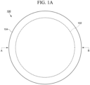
- FIG. 1 shows the structure of a metal mask 100 according to an embodiment of the present disclosure.
- FIG. 1A shows a plan view of the metal mask 100 and
- FIG. 1B shows a cross-sectional view corresponding to A-B shown in the plan view.
- the metal mask 100 shown in FIG. 1A and FIG. 1B is a fixture used in a thermal spraying process to mask the part of a workpiece that does not form a film when a film is formed on the surface of the workpiece by thermal spraying.
- the metal mask 100 has a flat (or disc-shaped) appearance and has a first surface S11 in contact with the workpiece, a second surface S12 opposite the first surface S11 and a third surface S13 between the first surface S11 and the second surface S12.
- the first surface S11 of the metal mask 100 corresponds to the bottom surface
- the second surface S12 corresponds to the top surface
- the third surface S13 corresponds to the side surface.
- the metal mask 100 can be divided into configuration elements: the body 102, which mainly forms the first surface S11 and the second surface S12, and the third surface S13 (side surface), and an eave portion 104, which is arranged above the body 102 and protrudes in the width direction.
- the first surface S11 of the body 102 is the part in direct contact with the workpiece.
- a step portion 106 is arranged on the third surface S13 (side surface), and the step portion 106 may be regarded as forming the eave portion 104.
- FIG. 1B shows a single step shape, but the step portion 106 may be formed by a plurality of steps.
- the metal mask 100 having such an appearance is provided as an integrally molded part.
- the metal mask 100 may have a structure in which the body 102 and the part forming the eave portion 104 are provided as separate parts, and both parts are assembled to form a single unit.
- the body 102 is a portion in direct contact with the workpiece and is also the main portion that masks the workpiece with a surface to prevent the formation of a film during thermal spraying.
- the first surface S11 of the body 102 has a shape that enables the entire surface of the body 102 to be in contact with the workpiece. For example, when the masked surface of the workpiece is flat, the first surface S11 of the body 102 also has a flat shape.
- the first surface S11 of the body 102 has a step structure formed to fit into the step of the masked surface.
- the eave portion 104 has the function of adjusting a range of film deposition so that the film does not form directly on the sides of the body 102. Therefore, the eave portion 104 is preferably arranged over the entire circumference of the body 102.
- the eave portion 104 has a function as a handle when the operator attaches or removes the metal mask 100 to or from the workpiece or carries it in their hand.
- the eave portion 104 on the metal mask 100 facilitates attachment and removal of the metal mask 100 and prevents direct contact with the surface of the workpiece and the deposited film.
- FIG. 1A and FIG. 1B show that the body 102 and the eave portion 104 configuring the metal mask 100 have different outer diameters. Specifically, an external diameter D2 of the eave portion 104 is larger than an external diameter D1 of the body 102. Due to this dimensional relationship, the metal mask 100 has a shape where the eave portion 104 protrudes from the body 102. A length P1 of the eave portion 104 protruding from the body 102 may be constant over the entire circumference or may vary in parts.
- the external diameter D1 of the body 102 and the external diameter D2 of the eave portion 104 are set appropriately to suit the size of the workpiece, which is the masking object. As the eave portion 104 is projected outwards in relation to the body 102, the external diameter D1 and the external diameter D2 have the relationship D1 ⁇ D2. On the other hand, a height H1 of the body 102 and the length P1 of the protruding eave portion 104 are adjusted as appropriate, taking into account the thickness of the film to be deposited, the shape of the workpiece and the region where the film is to be formed, the conditions of the thermal spraying, and other factors.
- the molten or softened material sprayed during thermal spraying is ideally sprayed from a direction that is perpendicular to the surface of the metal mask 100.
- the area under the eave portion 104 is shaded and the sprayed molten or softened material acts to prevent a film from being deposited, although the film is formed with some thickness even in the shaded area of the eave portion 104 due to the run-off of the sprayed thermal spray material.
- the film can be prevented from being deposited on the sides of the body 102.
- the thickness of the film formed under the eave portion 104 by the thermal spraying process can be adjusted according to the length P1 of the protruding eave portion 104 and the height H1 of the body 102.
- the height H1 of the body 102 when the height H1 of the body 102 is changed while the length P1 of the eave portion 104 is kept constant, a larger height H1 can increase the depth to which the thermal spraying material can come around, while a smaller height H1 can relatively shorten the depth to which the thermal spraying material can come around.
- the height H1 of the body 102 needs to be larger than the film thickness of the film so that it is not embedded in the film deposited by the thermal spray process. Specifically, the height of the body 102 is to be 0.5 mm to 1.0 mm thicker than the film thickness of the film to be deposited.
- the length P1 of the protruding eave portion 104 is 0.5 mm to 10 mm, preferably 1 mm to 3 mm, taking into account the wraparound of the thermal spraying material.
- the external diameter D2 of the eave portion 104 can be changed independently of the external diameter D1 of the body 102, the length P1 of the protruding eave portion 104 can be freely adjusted.
- the height H1 of the body 102 can also be set independently.
- the size and shape of the metal mask 100 may be changed according to various shapes of the workpiece. Since the metal mask 100 shown in FIG. 1A and FIG. 1B has a disk-like shape, it may be applied when the masking portion of the workpiece is circular. When the masking area for the workpiece is rectangular, the shape of the metal mask 100 in a plan view can be changed accordingly.
- the metal mask 100 may be applied to various thermal spraying materials. Metals, alloys, cermet, and ceramics are examples of thermal spray materials. In the thermal spray process, the thermal spray material is sprayed onto the workpiece, including the area to which the metal mask 100 is attached. The film formed on the surface of the workpiece by the thermal spray process is preferably firmly adhered, but it is preferable that the thermal spray material does not adhere to the surface of the metal mask 100 (it is difficult to adhere) or can be easily removed even if it does adhere to the surface of the metal mask 100. The metal mask 100 should have a heat resistance temperature that can withstand the temperature during thermal spraying.
- the body 102 and the eave portion 104 are made of metal, the body 102 and the eave portion 104 are formed of a resin material, or the body 102 and the eave portion 104 are made of metal and the surface is coated with a resin material.
- the resin material is preferably a fluoroplastic due to its heat resistance and the ease of removing the film formed by the thermal spraying process, for example, polytetrafluoroethylene (PTFE).
- FIG. 2A and FIG. 2B show the metal mask 100 attached to a workpiece 200.
- FIG. 2A shows a cross-sectional view of the metal mask 100 and the workpiece 200
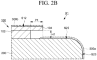
- FIG. 2B shows an enlarged view of the region X1 shown in FIG. 2A .
- the workpiece 200 shown in FIG. 2A and FIG. 2B represents a substrate stage that supports a semiconductor substrate or glass substrate in a semiconductor manufacturing apparatus
- the metal mask 100 is attached to a second surface S22 of the workpiece 200
- a film 300a formed by thermal spraying is shown in dotted lines that covers a first surface S21, a third surface S23, and the periphery of the second surface S22.
- the shape of the workpiece 200 which is illustrated is an example, and the workpiece to which the metal mask 100 of the present disclosure is applied is not limited to this shape.
- the workpiece 200 is not limited in shape as long as the metal mask 100 is attached to the area where the film is formed by thermal spraying.
- the metal mask 100 is attached to the second surface S22 of the workpiece 200 on which the film is formed by thermal spraying.
- the metal mask 100 has the same shape as shown in FIG. 1A and FIG. 1B and is attached so that the inner portion of the second surface S22 of the workpiece 200 is masked and the periphery is exposed.
- the workpiece 200 is set in a rotating machine and the thermal spraying process is performed while rotating the workpiece 200.
- the metal mask 100 may be fixed by a vacuum chuck using the structure of the workpiece 200 or may be fastened by screws or other components.
- the metal mask 100 may also be attached to the workpiece 200 and a center of the metal mask 100 may be held from the top by a rotating mounting fixture.
- the film 300a formed by the thermal spraying process is formed from the third surface S23 to the periphery of the second surface S22 of the workpiece 200, as shown by the dotted line.
- the film 300a is also formed on the top surface of the metal mask 100.
- the metal mask 100 is arranged in contact with the second surface S22 of the workpiece 200, and the eave portion 104 protrudes from the body 102 with the length P1 in the direction of the periphery of the workpiece 200.
- the molten or softened thermal spray material sprayed in the thermal spray process is not deposited directly on the underside of the eave portion 104 because it is shaded, but a film 300a is formed to the inside of the eave portion 104 by a portion which comes around.
- a film 300b is also deposited on the top surface of the metal mask 100 (second surface S12).
- the film 300a on the side of the workpiece 200 and the film 300b on the side of the metal mask 100 are discontinuous because the eave portion 104 is lifted off the workpiece 200 by the height H1 of the body 102 of the metal mask 100.
- the film 300a and the film 300b are discontinuous due to the eave portion 104 protruding at the length P1.
- the film 300a deposited under the eave portion 104 extends from the region overlapping an edge of the eave portion 104 to the region below the eave portion 300, but the length of the eave portion 104 is preferably set so that the film 300a does not reach the body 102.
- the film 300a deposited under the eave portion 104 may have a constant thickness, it is preferred that the thickness of the film 300a gradually decreases from the region overlapping the edge of the eave portion 104 towards the inside, as shown schematically in FIG. 2A and FIG. 2B .
- the gradual thinning of the film thickness of the film 300a at the edges can prevent peeling at the boundaries of the masking.
- the film thickness of the film 300a formed by the thermal spraying process is around 100 ⁇ m to 1500 ⁇ m. It is preferable that the metal mask 100 attached to the surface of the workpiece 200 is sufficiently thicker than the film thickness of the film 300, as it becomes difficult to remove the metal mask 100 if it is embedded by the film 300 (300a, 300b).
- the shape of the eave portion 104 of the metal mask 100 is not limited to the shapes shown in FIG. 1A and FIG. 1B .
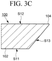
- the third surface S13 of the metal mask 100 (side of the body 102) may have an inclined surface (tapered shape) that widens from the first surface S11 to the second surface S12.
- the inclined surface of the body 102 is discontinuously connected to the eave portion 104 to form the step portion 106 and to form a structure in which the eave portion 104 protrudes. It is possible to stabilize the shape of the eave portion 104 by the sloping surface of the body 102, thereby preventing deformation.
- the inclined surface of the body 102 may be formed with a curved surface.
- the sloping surface of the third surface S13 of the body 102 may be continuous from the first surface S11 to the second surface S12.
- the eave portion 104 may be formed by an edge of the second surface S12 protruding outwards with respect to an edge of the first surface S11.
- the inclined surface may have a curved surface shape.
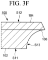
- FIG. 3E and FIG. 3F have the same shape as FIG. 3A and FIG. 3B , but differ in that the sides of the eave portion 104 have a tapered shape that tapers inwards. It is possible to prevent the deposition of the sprayed film on the sides of the eave portion 104 while keeping the strength of the metal mask 100 during the thermal spraying process by having such a tapered shape of the edge of the eave portion 104.
- the thermal spray gun is not only directed from above the metal mask 100, but also from the side of the workpiece 200.
- the eave portion 104 of the metal mask 100 has a tapered shape, it is possible to prevent the film from being deposited on the side surface, and even if there is deposition on the side surface, the amount of the film can be reduced.
- the metal mask 100 with the shape shown in FIG. 3A to FIG. 3F has an inclined portion in the body 102 and the eave portion 104 above this inclined portion, so that the film 300b deposited on the workpiece 200 and the film 300a deposited on the metal mask 100 are discontinuous.
- the metal mask 100 has the eave portion 104, so that the film 300a deposited on the workpiece 200 by the thermal spraying process and the film 300b deposited on the metal mask 100 can be discontinuous. Thereby, it is possible to avoid damaging the film 300a when the metal mask 100 is removed after the thermal spraying process. Therefore, cracks in the film 300a formed on the workpiece 200 and delamination at the boundary with the metal mask 100 can be prevented. It is thus possible to improve the quality of the workpiece 200 to which the thermal spraying treatment is applied.
Landscapes
- Chemical & Material Sciences (AREA)
- Engineering & Computer Science (AREA)
- Organic Chemistry (AREA)
- Materials Engineering (AREA)
- Mechanical Engineering (AREA)
- Metallurgy (AREA)
- Chemical Kinetics & Catalysis (AREA)
- Physics & Mathematics (AREA)
- Plasma & Fusion (AREA)
- Coating By Spraying Or Casting (AREA)
- Details Or Accessories Of Spraying Plant Or Apparatus (AREA)
- Physical Vapour Deposition (AREA)
- Container, Conveyance, Adherence, Positioning, Of Wafer (AREA)
Abstract
Description
- The present disclosure relates to the structure of a metal mask that can be used for thermal spraying on a workpiece.
- A technology is disclosed for spraying a ceramic insulating film onto a metal workpiece (also called "base material" or "component") in order to provide a high voltage and heat resistance (for example, Patent Literature 1).
- Patent Literature 1:
Japanese Unexamined Patent Application Publication No. 2014-013874 - Since the formation of a film by thermal spraying involves melting a material such as metal or ceramics using a heat source and injecting the molten particles into a workpiece to form a film, it is difficult to accurately separate the areas where a film is deposited from areas where no film is deposited. Therefore, it is necessary to mask the areas on the workpiece where the film is not to be deposited beforehand.
- For example, masking materials such as masking tape are provided to prevent thermal spray coatings from being deposited on a part of the surface of the workpiece. However, the film deposited by the thermal spraying process is continuously deposited not only on the surface of the workpiece but also on the masking material, which causes cracks in the film when the masking material is removed, and also causes peeling at the boundary with the mask.
- In view of these problems, the purpose of the present disclosure is to provide a fixture that enables easy masking when forming a film on the surface of a workpiece by thermal spraying and that does not cause damage to the film deposited on the workpiece.
- A metal mask in an embodiment according to the present invention includes a body having a first surface in contact with a surface of a workpiece, a second surface opposite the first surface and a third surface between the first surface and the second surface, and an eave portion continuous from the body and projecting externally from the first surface. The eave portion is arranged away from the surface of the workpiece.
- In an embodiment of the present disclosure, the third surface (side surface) pertaining to the body of the metal mask may have a stepped portion arranged to form an eave portion. The third surface (side surface) of the body may have a structure in which the eave portion is arranged above a sloping surface, with the sloping surface widening from the first surface to the second surface.
- The metal mask according to an embodiment of the present disclosure may have the body and the eave portion made of metal, the body and the eave portion made of resin, or the body and the eave portion made of metal and the surface masked with resin.
- According to an embodiment of the present disclosure, it is possible to prevent damage to the film formed by thermal spraying when the metal mask is removed from the workpiece, by providing the metal mask with an eave portion arranged away from the surface of the workpiece and not in direct contact with it.
-
-
FIG. 1A is a plan view of a metal mask according to an embodiment of the present disclosure. -
FIG. 1B is a cross-sectional view of a metal mask according to an embodiment of the present disclosure. -
FIG. 2A is a plan view showing a metal mask attached to a workpiece according to an embodiment of the present disclosure. -
FIG. 2B is an illustration of a metal mask attached to a workpiece according to an embodiment of the present disclosure and shows an enlarged view of the region X1 shown inFIG. 2A . -
FIG. 3A is a cross-sectional view of a body and an eave portion of a metal mask according to an embodiment of the present disclosure. -
FIG. 3B is a cross-sectional view of a body and an eave portion of a metal mask according to an embodiment of the present disclosure. -
FIG. 3C is a cross-sectional view of a body and an eave portion of a metal mask according to an embodiment of the present disclosure. -
FIG. 3D is a cross-sectional view of a body and an eave portion of a metal mask according to an embodiment of the present disclosure. -
FIG. 3E is a cross-sectional view of a body and an eave portion of a metal mask according to an embodiment of the present disclosure. -
FIG. 3F is a cross-sectional view of a body and an eave portion of a metal mask according to an embodiment of the present disclosure. - Hereinafter, each embodiment of the present disclosure will be described with reference to drawings and the like. However, the present disclosure may be implemented in various ways to the extent that it does not deviate from the gist thereof and shall not be construed as being limited to the description of the embodiments illustrated below.
- The drawings may be represented schematically with respect to the width, thickness, shape, and the like of each portion in comparison with the actual embodiment in order to make the description clearer, but they are examples only and do not limit the interpretation of the present disclosure. In this description and the drawings, elements having functions similar to those described with reference to existing drawings may be denoted by the same reference numerals and duplicate descriptions may be omitted.
-
FIG. 1 shows the structure of ametal mask 100 according to an embodiment of the present disclosure.FIG. 1A shows a plan view of themetal mask 100 andFIG. 1B shows a cross-sectional view corresponding to A-B shown in the plan view. Themetal mask 100 shown inFIG. 1A andFIG. 1B is a fixture used in a thermal spraying process to mask the part of a workpiece that does not form a film when a film is formed on the surface of the workpiece by thermal spraying. - The
metal mask 100 has a flat (or disc-shaped) appearance and has a first surface S11 in contact with the workpiece, a second surface S12 opposite the first surface S11 and a third surface S13 between the first surface S11 and the second surface S12. The first surface S11 of themetal mask 100 corresponds to the bottom surface, the second surface S12 corresponds to the top surface and the third surface S13 corresponds to the side surface. - The
metal mask 100 can be divided into configuration elements: thebody 102, which mainly forms the first surface S11 and the second surface S12, and the third surface S13 (side surface), and aneave portion 104, which is arranged above thebody 102 and protrudes in the width direction. The first surface S11 of thebody 102 is the part in direct contact with the workpiece. - As shown in
FIG. 1B , when themetal mask 100 is viewed in a cross-section, astep portion 106 is arranged on the third surface S13 (side surface), and thestep portion 106 may be regarded as forming theeave portion 104.FIG. 1B shows a single step shape, but thestep portion 106 may be formed by a plurality of steps. - The
metal mask 100 having such an appearance is provided as an integrally molded part. Themetal mask 100 may have a structure in which thebody 102 and the part forming theeave portion 104 are provided as separate parts, and both parts are assembled to form a single unit. - The
body 102 and theeave portion 104, which configure themetal mask 100, each have a different function. Thebody 102 is a portion in direct contact with the workpiece and is also the main portion that masks the workpiece with a surface to prevent the formation of a film during thermal spraying. To enable themetal mask 100 to be attached stably to the workpiece, the first surface S11 of thebody 102 has a shape that enables the entire surface of thebody 102 to be in contact with the workpiece. For example, when the masked surface of the workpiece is flat, the first surface S11 of thebody 102 also has a flat shape. When the masked surface of the workpiece includes a step, the first surface S11 of thebody 102 has a step structure formed to fit into the step of the masked surface. - The
eave portion 104 has the function of adjusting a range of film deposition so that the film does not form directly on the sides of thebody 102. Therefore, theeave portion 104 is preferably arranged over the entire circumference of thebody 102. Theeave portion 104 has a function as a handle when the operator attaches or removes themetal mask 100 to or from the workpiece or carries it in their hand. Theeave portion 104 on themetal mask 100 facilitates attachment and removal of themetal mask 100 and prevents direct contact with the surface of the workpiece and the deposited film. -
FIG. 1A andFIG. 1B show that thebody 102 and theeave portion 104 configuring themetal mask 100 have different outer diameters. Specifically, an external diameter D2 of theeave portion 104 is larger than an external diameter D1 of thebody 102. Due to this dimensional relationship, themetal mask 100 has a shape where theeave portion 104 protrudes from thebody 102. A length P1 of theeave portion 104 protruding from thebody 102 may be constant over the entire circumference or may vary in parts. - The external diameter D1 of the
body 102 and the external diameter D2 of theeave portion 104 are set appropriately to suit the size of the workpiece, which is the masking object. As theeave portion 104 is projected outwards in relation to thebody 102, the external diameter D1 and the external diameter D2 have the relationship D1 < D2. On the other hand, a height H1 of thebody 102 and the length P1 of the protrudingeave portion 104 are adjusted as appropriate, taking into account the thickness of the film to be deposited, the shape of the workpiece and the region where the film is to be formed, the conditions of the thermal spraying, and other factors. - The molten or softened material sprayed during thermal spraying is ideally sprayed from a direction that is perpendicular to the surface of the
metal mask 100. When themetal mask 100 is attached to the workpiece, the area under theeave portion 104 is shaded and the sprayed molten or softened material acts to prevent a film from being deposited, although the film is formed with some thickness even in the shaded area of theeave portion 104 due to the run-off of the sprayed thermal spray material. When the length P1 of theeave portion 104 is sufficiently long, that is, when the protruding length P1 of theeave portion 104 is longer than the distance that the sprayed thermal spray material comes around the underside of theeave portion 104, the film can be prevented from being deposited on the sides of thebody 102. In other words, the thickness of the film formed under theeave portion 104 by the thermal spraying process can be adjusted according to the length P1 of the protrudingeave portion 104 and the height H1 of thebody 102. For example, when the height H1 of thebody 102 is changed while the length P1 of theeave portion 104 is kept constant, a larger height H1 can increase the depth to which the thermal spraying material can come around, while a smaller height H1 can relatively shorten the depth to which the thermal spraying material can come around. The height H1 of thebody 102 needs to be larger than the film thickness of the film so that it is not embedded in the film deposited by the thermal spray process. Specifically, the height of thebody 102 is to be 0.5 mm to 1.0 mm thicker than the film thickness of the film to be deposited. The length P1 of the protrudingeave portion 104 is 0.5 mm to 10 mm, preferably 1 mm to 3 mm, taking into account the wraparound of the thermal spraying material. - The length P1 of the
eave portion 104 protruding from thebody 102 has the relationship P1 = 1/2 (D2 - D1). As the external diameter D2 of theeave portion 104 can be changed independently of the external diameter D1 of thebody 102, the length P1 of the protrudingeave portion 104 can be freely adjusted. As is apparent from the structure shown inFIG. 1B , the height H1 of thebody 102 can also be set independently. - The size and shape of the
metal mask 100 may be changed according to various shapes of the workpiece. Since themetal mask 100 shown inFIG. 1A andFIG. 1B has a disk-like shape, it may be applied when the masking portion of the workpiece is circular. When the masking area for the workpiece is rectangular, the shape of themetal mask 100 in a plan view can be changed accordingly. - The
metal mask 100 may be applied to various thermal spraying materials. Metals, alloys, cermet, and ceramics are examples of thermal spray materials. In the thermal spray process, the thermal spray material is sprayed onto the workpiece, including the area to which themetal mask 100 is attached. The film formed on the surface of the workpiece by the thermal spray process is preferably firmly adhered, but it is preferable that the thermal spray material does not adhere to the surface of the metal mask 100 (it is difficult to adhere) or can be easily removed even if it does adhere to the surface of themetal mask 100. Themetal mask 100 should have a heat resistance temperature that can withstand the temperature during thermal spraying. - In order for the
metal mask 100 to meet these conditions, it is preferable that thebody 102 and theeave portion 104 are made of metal, thebody 102 and theeave portion 104 are formed of a resin material, or thebody 102 and theeave portion 104 are made of metal and the surface is coated with a resin material. The resin material is preferably a fluoroplastic due to its heat resistance and the ease of removing the film formed by the thermal spraying process, for example, polytetrafluoroethylene (PTFE). -
FIG. 2A andFIG. 2B show themetal mask 100 attached to aworkpiece 200.FIG. 2A shows a cross-sectional view of themetal mask 100 and theworkpiece 200, andFIG. 2B shows an enlarged view of the region X1 shown inFIG. 2A . Theworkpiece 200 shown inFIG. 2A andFIG. 2B represents a substrate stage that supports a semiconductor substrate or glass substrate in a semiconductor manufacturing apparatus, themetal mask 100 is attached to a second surface S22 of theworkpiece 200, and afilm 300a formed by thermal spraying is shown in dotted lines that covers a first surface S21, a third surface S23, and the periphery of the second surface S22. - The shape of the
workpiece 200 which is illustrated is an example, and the workpiece to which themetal mask 100 of the present disclosure is applied is not limited to this shape. Theworkpiece 200 is not limited in shape as long as themetal mask 100 is attached to the area where the film is formed by thermal spraying. - As shown in
FIG. 2A , themetal mask 100 is attached to the second surface S22 of theworkpiece 200 on which the film is formed by thermal spraying. Themetal mask 100 has the same shape as shown inFIG. 1A andFIG. 1B and is attached so that the inner portion of the second surface S22 of theworkpiece 200 is masked and the periphery is exposed. Theworkpiece 200 is set in a rotating machine and the thermal spraying process is performed while rotating theworkpiece 200. Themetal mask 100 may be fixed by a vacuum chuck using the structure of theworkpiece 200 or may be fastened by screws or other components. Themetal mask 100 may also be attached to theworkpiece 200 and a center of themetal mask 100 may be held from the top by a rotating mounting fixture. - As shown in the enlarged view in
FIG. 2B , thefilm 300a formed by the thermal spraying process is formed from the third surface S23 to the periphery of the second surface S22 of theworkpiece 200, as shown by the dotted line. Thefilm 300a is also formed on the top surface of themetal mask 100. Themetal mask 100 is arranged in contact with the second surface S22 of theworkpiece 200, and theeave portion 104 protrudes from thebody 102 with the length P1 in the direction of the periphery of theworkpiece 200. The molten or softened thermal spray material sprayed in the thermal spray process is not deposited directly on the underside of theeave portion 104 because it is shaded, but afilm 300a is formed to the inside of theeave portion 104 by a portion which comes around. Afilm 300b is also deposited on the top surface of the metal mask 100 (second surface S12). However, thefilm 300a on the side of theworkpiece 200 and thefilm 300b on the side of themetal mask 100 are discontinuous because theeave portion 104 is lifted off theworkpiece 200 by the height H1 of thebody 102 of themetal mask 100. Thefilm 300a and thefilm 300b are discontinuous due to theeave portion 104 protruding at the length P1. - The
film 300a deposited under theeave portion 104 extends from the region overlapping an edge of theeave portion 104 to the region below the eave portion 300, but the length of theeave portion 104 is preferably set so that thefilm 300a does not reach thebody 102. Although thefilm 300a deposited under theeave portion 104 may have a constant thickness, it is preferred that the thickness of thefilm 300a gradually decreases from the region overlapping the edge of theeave portion 104 towards the inside, as shown schematically inFIG. 2A andFIG. 2B . The gradual thinning of the film thickness of thefilm 300a at the edges can prevent peeling at the boundaries of the masking. - The film thickness of the
film 300a formed by the thermal spraying process is around 100 µm to 1500 µm. It is preferable that themetal mask 100 attached to the surface of theworkpiece 200 is sufficiently thicker than the film thickness of the film 300, as it becomes difficult to remove themetal mask 100 if it is embedded by the film 300 (300a, 300b). - The shape of the
eave portion 104 of themetal mask 100 is not limited to the shapes shown inFIG. 1A andFIG. 1B . For example, as shown inFIG. 3A , the third surface S13 of the metal mask 100 (side of the body 102) may have an inclined surface (tapered shape) that widens from the first surface S11 to the second surface S12. The inclined surface of thebody 102 is discontinuously connected to theeave portion 104 to form thestep portion 106 and to form a structure in which theeave portion 104 protrudes. It is possible to stabilize the shape of theeave portion 104 by the sloping surface of thebody 102, thereby preventing deformation. As shown inFIG. 3B , the inclined surface of thebody 102 may be formed with a curved surface. - Furthermore, as shown in
FIG. 3C , the sloping surface of the third surface S13 of thebody 102 may be continuous from the first surface S11 to the second surface S12. Theeave portion 104 may be formed by an edge of the second surface S12 protruding outwards with respect to an edge of the first surface S11. As shown inFIG. 3D , the inclined surface may have a curved surface shape. -
FIG. 3E andFIG. 3F have the same shape asFIG. 3A andFIG. 3B , but differ in that the sides of theeave portion 104 have a tapered shape that tapers inwards. It is possible to prevent the deposition of the sprayed film on the sides of theeave portion 104 while keeping the strength of themetal mask 100 during the thermal spraying process by having such a tapered shape of the edge of theeave portion 104. In the thermal spraying process, the thermal spray gun is not only directed from above themetal mask 100, but also from the side of theworkpiece 200. In such a case, since theeave portion 104 of themetal mask 100 has a tapered shape, it is possible to prevent the film from being deposited on the side surface, and even if there is deposition on the side surface, the amount of the film can be reduced. - The
metal mask 100 with the shape shown inFIG. 3A to FIG. 3F has an inclined portion in thebody 102 and theeave portion 104 above this inclined portion, so that thefilm 300b deposited on theworkpiece 200 and thefilm 300a deposited on themetal mask 100 are discontinuous. - As explained above, the
metal mask 100 according to the present disclosure has theeave portion 104, so that thefilm 300a deposited on theworkpiece 200 by the thermal spraying process and thefilm 300b deposited on themetal mask 100 can be discontinuous. Thereby, it is possible to avoid damaging thefilm 300a when themetal mask 100 is removed after the thermal spraying process. Therefore, cracks in thefilm 300a formed on theworkpiece 200 and delamination at the boundary with themetal mask 100 can be prevented. It is thus possible to improve the quality of theworkpiece 200 to which the thermal spraying treatment is applied. -
- 100:
- metal mask,
- 102:
- body,
- 104:
- eave portion,
- 106:
- step portion,
- 200:
- workpiece,
- 300:
- film
Claims (4)
- A metal mask, comprising:a body having a first surface in contact with a surface of a workpiece, a second surface opposite the first surface and a third surface between the first surface and the second surface; andan eave portion continuous from the body and projecting externally from the first surface,wherein the eave portion is arranged away from the surface of the workpiece.
- The metal mask according to claim 1, wherein the third surface includes a step portion forming the eave portion.
- The metal mask according to claim 1, wherein the third surface has a sloping surface extending from the first surface towards the second surface, and the eave portion is arranged above the sloping surface.
- The metal mask according to any one of claims 1 to 3, wherein the body and the eave portion are made of metal, the body and the eave portion are made of resin, or the body and the eave portion are made of metal and covered with resin on the surface.
Applications Claiming Priority (2)
| Application Number | Priority Date | Filing Date | Title |
|---|---|---|---|
| JP2021004723U JP3236293U (en) | 2021-12-10 | 2021-12-10 | Metal mask |
| PCT/JP2022/043571 WO2023106131A1 (en) | 2021-12-10 | 2022-11-25 | Metal mask |
Publications (2)
| Publication Number | Publication Date |
|---|---|
| EP4446455A1 true EP4446455A1 (en) | 2024-10-16 |
| EP4446455A4 EP4446455A4 (en) | 2025-08-06 |
Family
ID=80159122
Family Applications (1)
| Application Number | Title | Priority Date | Filing Date |
|---|---|---|---|
| EP22904062.1A Pending EP4446455A4 (en) | 2021-12-10 | 2022-11-25 | METAL MASK |
Country Status (7)
| Country | Link |
|---|---|
| US (1) | US20240327967A1 (en) |
| EP (1) | EP4446455A4 (en) |
| JP (1) | JP3236293U (en) |
| KR (1) | KR20240110623A (en) |
| CN (1) | CN118369457A (en) |
| TW (1) | TWI837995B (en) |
| WO (1) | WO2023106131A1 (en) |
Family Cites Families (7)
| Publication number | Priority date | Publication date | Assignee | Title |
|---|---|---|---|---|
| JPS59160569A (en) * | 1983-03-03 | 1984-09-11 | Sumitomo Metal Ind Ltd | Partial melt-spraying method |
| JPH0593254A (en) * | 1991-09-30 | 1993-04-16 | Sumitomo Metal Ind Ltd | Metal joining method |
| JP4066329B2 (en) * | 2002-09-05 | 2008-03-26 | 太平洋セメント株式会社 | Electrostatic chuck manufacturing method and electrostatic chuck obtained using the same |
| JP4326874B2 (en) * | 2003-08-07 | 2009-09-09 | 太平洋セメント株式会社 | Electrostatic chuck and manufacturing method thereof |
| US10276410B2 (en) | 2011-11-25 | 2019-04-30 | Nhk Spring Co., Ltd. | Substrate support device |
| TWI763818B (en) * | 2017-03-31 | 2022-05-11 | 日商大日本印刷股份有限公司 | Vapor deposition mask, vapor deposition mask with frame, vapor deposition mask preparation body, vapor deposition pattern forming method, and manufacturing method of organic semiconductor element |
| JP3236603U (en) * | 2021-12-29 | 2022-03-02 | 日本発條株式会社 | Masking jig |
-
2021
- 2021-12-10 JP JP2021004723U patent/JP3236293U/en active Active
-
2022
- 2022-11-25 WO PCT/JP2022/043571 patent/WO2023106131A1/en not_active Ceased
- 2022-11-25 KR KR1020247019755A patent/KR20240110623A/en active Pending
- 2022-11-25 EP EP22904062.1A patent/EP4446455A4/en active Pending
- 2022-11-25 CN CN202280077351.5A patent/CN118369457A/en active Pending
- 2022-12-07 TW TW111146984A patent/TWI837995B/en active
-
2024
- 2024-06-10 US US18/738,218 patent/US20240327967A1/en active Pending
Also Published As
| Publication number | Publication date |
|---|---|
| US20240327967A1 (en) | 2024-10-03 |
| EP4446455A4 (en) | 2025-08-06 |
| TW202328469A (en) | 2023-07-16 |
| JP3236293U (en) | 2022-02-09 |
| KR20240110623A (en) | 2024-07-15 |
| TWI837995B (en) | 2024-04-01 |
| CN118369457A (en) | 2024-07-19 |
| WO2023106131A1 (en) | 2023-06-15 |
Similar Documents
| Publication | Publication Date | Title |
|---|---|---|
| CN100523276C (en) | Design of hardware features to facilitate arc-spray coating applications and functions | |
| TWI537409B (en) | Masking ring for modifying wafer edge and bevel deposition and method of making the same | |
| KR102311487B1 (en) | Method of manufacturing semiconductor package | |
| JP2004523350A5 (en) | ||
| US20240342740A1 (en) | Masking fixture | |
| US7717058B2 (en) | Method of preparing turbine blades for spray coating and mounting for fixing such a turbine blade | |
| US20240327967A1 (en) | Metal mask | |
| JP4796430B2 (en) | How to apply protective tape | |
| KR100591433B1 (en) | Shielding and coating method for titanium nitride sputtering process | |
| US6495205B1 (en) | Linear extrusion coating system and method | |
| CN107245693A (en) | Mask assembly, vacuum coater and its application method | |
| CN108603274A (en) | For cover should with thermal jet coating the method for the component of coating | |
| JPH1030174A (en) | Sputtering device and method for working backing plate used for the same device | |
| CN117867439B (en) | Process for manufacturing coating on surface of product | |
| CN223705692U (en) | A semiconductor Cover Ring melt protection device | |
| US20240136159A1 (en) | Metallic Shield For Stable Tape-Frame Substrate Processing | |
| JP2020090710A (en) | Thermal spraying member and manufacturing method thereof | |
| KR102741639B1 (en) | Substrate assembly and substrate bonding method | |
| JP2541844Y2 (en) | Jig for holding hollow cylindrical endless belt | |
| KR200194583Y1 (en) | Gas distribution plate of process chamber | |
| JP2004097896A (en) | Ring coating method and its coating head | |
| JPH0453225A (en) | Resist coater | |
| JPS6146028A (en) | Resist coater | |
| JPS60189937A (en) | Applicator of resist | |
| JPS6235568A (en) | Semiconductor device |
Legal Events
| Date | Code | Title | Description |
|---|---|---|---|
| STAA | Information on the status of an ep patent application or granted ep patent |
Free format text: STATUS: THE INTERNATIONAL PUBLICATION HAS BEEN MADE |
|
| PUAI | Public reference made under article 153(3) epc to a published international application that has entered the european phase |
Free format text: ORIGINAL CODE: 0009012 |
|
| STAA | Information on the status of an ep patent application or granted ep patent |
Free format text: STATUS: REQUEST FOR EXAMINATION WAS MADE |
|
| 17P | Request for examination filed |
Effective date: 20240607 |
|
| AK | Designated contracting states |
Kind code of ref document: A1 Designated state(s): AL AT BE BG CH CY CZ DE DK EE ES FI FR GB GR HR HU IE IS IT LI LT LU LV MC ME MK MT NL NO PL PT RO RS SE SI SK SM TR |
|
| DAV | Request for validation of the european patent (deleted) | ||
| DAX | Request for extension of the european patent (deleted) | ||
| REG | Reference to a national code |
Ref country code: DE Ref legal event code: R079 Free format text: PREVIOUS MAIN CLASS: C23C0004020000 Ipc: C23C0004010000 |
|
| A4 | Supplementary search report drawn up and despatched |
Effective date: 20250708 |
|
| RIC1 | Information provided on ipc code assigned before grant |
Ipc: C23C 4/01 20160101AFI20250702BHEP Ipc: C23C 4/02 20060101ALI20250702BHEP Ipc: C23C 14/04 20060101ALI20250702BHEP Ipc: B05D 1/32 20060101ALI20250702BHEP |