EP4446273A1 - Method for operating a crane, indicator element and a system - Google Patents
Method for operating a crane, indicator element and a system Download PDFInfo
- Publication number
- EP4446273A1 EP4446273A1 EP23167822.8A EP23167822A EP4446273A1 EP 4446273 A1 EP4446273 A1 EP 4446273A1 EP 23167822 A EP23167822 A EP 23167822A EP 4446273 A1 EP4446273 A1 EP 4446273A1
- Authority
- EP
- European Patent Office
- Prior art keywords
- crane
- indicator element
- jib
- indicator
- movement
- Prior art date
- Legal status (The legal status is an assumption and is not a legal conclusion. Google has not performed a legal analysis and makes no representation as to the accuracy of the status listed.)
- Pending
Links
Images

Classifications
-
- B—PERFORMING OPERATIONS; TRANSPORTING
- B66—HOISTING; LIFTING; HAULING
- B66C—CRANES; LOAD-ENGAGING ELEMENTS OR DEVICES FOR CRANES, CAPSTANS, WINCHES, OR TACKLES
- B66C13/00—Other constructional features or details
- B66C13/18—Control systems or devices
- B66C13/46—Position indicators for suspended loads or for crane elements
-
- B—PERFORMING OPERATIONS; TRANSPORTING
- B66—HOISTING; LIFTING; HAULING
- B66C—CRANES; LOAD-ENGAGING ELEMENTS OR DEVICES FOR CRANES, CAPSTANS, WINCHES, OR TACKLES
- B66C13/00—Other constructional features or details
- B66C13/18—Control systems or devices
- B66C13/48—Automatic control of crane drives for producing a single or repeated working cycle; Program control
-
- B—PERFORMING OPERATIONS; TRANSPORTING
- B66—HOISTING; LIFTING; HAULING
- B66C—CRANES; LOAD-ENGAGING ELEMENTS OR DEVICES FOR CRANES, CAPSTANS, WINCHES, OR TACKLES
- B66C13/00—Other constructional features or details
- B66C13/04—Auxiliary devices for controlling movements of suspended loads, or preventing cable slack
- B66C13/06—Auxiliary devices for controlling movements of suspended loads, or preventing cable slack for minimising or preventing longitudinal or transverse swinging of loads
- B66C13/063—Auxiliary devices for controlling movements of suspended loads, or preventing cable slack for minimising or preventing longitudinal or transverse swinging of loads electrical
-
- B—PERFORMING OPERATIONS; TRANSPORTING
- B66—HOISTING; LIFTING; HAULING
- B66C—CRANES; LOAD-ENGAGING ELEMENTS OR DEVICES FOR CRANES, CAPSTANS, WINCHES, OR TACKLES
- B66C13/00—Other constructional features or details
- B66C13/16—Applications of indicating, registering, or weighing devices
-
- B—PERFORMING OPERATIONS; TRANSPORTING
- B66—HOISTING; LIFTING; HAULING
- B66C—CRANES; LOAD-ENGAGING ELEMENTS OR DEVICES FOR CRANES, CAPSTANS, WINCHES, OR TACKLES
- B66C23/00—Cranes comprising essentially a beam, boom, or triangular structure acting as a cantilever and mounted for translatory of swinging movements in vertical or horizontal planes or a combination of such movements, e.g. jib-cranes, derricks, tower cranes
- B66C23/58—Cranes comprising essentially a beam, boom, or triangular structure acting as a cantilever and mounted for translatory of swinging movements in vertical or horizontal planes or a combination of such movements, e.g. jib-cranes, derricks, tower cranes arranged to carry out a desired sequence of operations automatically, e.g. hoisting followed by luffing and slewing
-
- B—PERFORMING OPERATIONS; TRANSPORTING
- B66—HOISTING; LIFTING; HAULING
- B66C—CRANES; LOAD-ENGAGING ELEMENTS OR DEVICES FOR CRANES, CAPSTANS, WINCHES, OR TACKLES
- B66C23/00—Cranes comprising essentially a beam, boom, or triangular structure acting as a cantilever and mounted for translatory of swinging movements in vertical or horizontal planes or a combination of such movements, e.g. jib-cranes, derricks, tower cranes
- B66C23/62—Constructional features or details
- B66C23/64—Jibs
- B66C23/66—Outer or upper end constructions
Definitions
- the present invention relates to a method for operating a crane.
- the present invention further relates to an indicator element, a system with a tower crane or an overhead crane using said method and/or indicator element.
- Cranes are relatively compliant mechanical structures. Especially when moving or when operating a crane in manual or any remote mode configuration, for example when rotating a jib element, this can result in notable oscillations if a human operator directly controls the speed of the motion with an input device.
- an object of the present invention to provide a method for operating a crane. It is further an object of the invention to provide an indicator element, a system with a tower crane or an overhead crane using such a method.
- a method for operating a crane comprising the following steps: providing a crane with a jib element and an indicator element, wherein the jib element and the indicator element are arranged in a first position. Moving the indicator element from the first position to a second position. Moving the jib element from the first position to the second position, in particular after the indicator element is arranged in the second position.
- the crane may be of any type of cranes.
- the crane may be for example a construction/tower crane, indoor EOT overhead crane or harbor crane type cranes.
- the jib element may be any element, that needs to be aligned or moved to transport or transfer an object or a mass from the first position to the second position.
- the jib element is at least indirectly connected to the object or mass to be transported or to be transferred.
- the jib element may be for example a crane jib, an arm or a movable trolley.
- the movable trolley may be arranged on a crane jib or may be part of an overhead crane.
- the indicator element may be a visual help to indicate the second position or desired end position of the jib element.
- the indicator element may also be parameter data, like a distance or an angle to a reference point.
- the method according to the present invention allows the operator to control the indicator element. Once the indicator element has been positioned as desired, i.e. in the second position or the end position, the jib element moves to the second position in a control mode, with tailored controls making sure no oscillations occur. Thereby, cycle time reductions can be achieved, and the crane may be controlled easier by the operator. It may be possible that the jib element starts moving even though the indicator element is not yet in the second position.
- the method according to the present invention may be an assistive function. This means, the operator stays completely in charge of the crane motion. This means the method does not target any autonomous operation, hence perception and/or safety aspects are no concern.
- the method may speed up gross positioning of the crane, since optimized trajectory generation and position control may move faster without inducing oscillations compared to human operators, while still giving the operator control for manual fine positioning.
- the movement of the jib element from the first position to the second position is triggered manually or automatically. Additionally or alternatively, the movement of the indicator element from the first position to the second position is triggered manually or automatically.
- the jib element may be controlled directly by the operator. Meaning the operator starts the movement of the jib element by manipulating for example a joystick or a similar control device.
- the jib element and the indicator element preferably move simultaneously at least in partial areas of the movement. This allows the operator to see the second position or stop/end position of the jib element during its movement.
- the indicator element moves ahead of the jib element to the second position. More precisely, the indicator element may run ahead and the jib element may run behind.
- the second position of the indicator element is the position where the jib element would come to a standstill if the operator were to interrupt the movement at that time, for example by letting go of the joystick or set the speed reference to zero.
- the second position may also be described as dynamic second position. Due to the input filtering, the jib may not come to a stop immediately but may gently ramp down the speed.
- the operator manually triggers the movement of the jib element, after the indicator element is in the second position.
- the jib element may be controlled by the operator in a manual mode.
- a graphical display may be employed to visualize the ideal input.
- the graphical display may be for example shown on a monitor. This provides an assistive tool to the operator, as the operator is provided with an ideal trajectory to track.
- the jib element may be moved automatically based on a calculated motion profile, which may be generated after the indicator element is in the second position.
- the automatic movement may trigger automatically or manually by the operator after the indicator element is in the second position.
- the second position may also be a dynamic position. This means, the jib element may start moving although the indicator element has not yet stopped.
- an acoustic or haptic feedback may be provided while moving the jib element.
- an acoustic signal or haptic feedback via the joystick can be triggered once the operator is moving towards the target and the crane has reached the position from which the crane will converge to the desired target if the user lets go off the input device at the respective time instant.
- haptic queues in a force-feedback joystick may be employed, indicating if the operator is following the best possible input trajectory.
- the indicator element is part of the crane or connected to the crane.
- the indicator element is movable, for example linear or rotatable, connected or arranged at the crane.
- the indicator element may be a constructive part.
- the indicator element may be a protruding element, for example a web element or a similar hardware element.
- the indicator element may also be described as a marker element or a pointer element.
- the indicator element is preferably identifiable or visible when operating the crane. At standstill, the indicator element is parallel to the jib element. While in motion, the indicator element moves ahead or away from the jib element. The indicator element will immediately come to a stop if the operator stops providing input. Next, the jib element follows the movement of the indicator element.
- the indicator element is a digital and/or virtual indicator element.
- the indicator element may be a graphic element, displayed on a monitor, for example of a tablet, or an augmented reality device.
- a graphical display can show the same as the hardware indicator but as a virtual arrow pointing into the corresponding direction.
- the indicator element is provided as a virtual overlay on a graphical display, the position of the real crane may be illustrated with an overlay showing the position of the crane at the predicted stop position.
- the indicator element may also be provided as a numerical display. This could be for example a simple textual display which may show the predicted extra distance for example in degrees.
- the indicator element is configured to be seen with an augmented reality device.
- the operator may use augmented reality glasses with an augmented reality overlay or a similar device to move the indicator device into the second position. More precisely, an operator wearing AR glasses, a virtual overlay of the crane at the predicted stopping position may be superimposed to the real-world view of the actual crane.
- the automatic movement of the jib element is a controlled movement.
- the movement of the jib element comprises an anti-sway control and/or filtering, in particular notch-filtering and/or input shaping.
- Anti-sway typically refers to load sway.
- the position of the crane at the end of the prediction is obtained. This corresponds to the stop position, i.e. second position.
- the computation of the stop distance is computationally slim, it may be run online. If real-time execution requires, the sampling time of the simulation may be increased. This further speeds up computations at the cost of some loss of precision in the prediction.
- the calculation of the final indicator stop position may also be done with a dynamic model which describes the dynamics of a speed-controlled ideally stiff tower crane. Hence, no structural compliances and no load sway are respected at all.
- This dynamic model is then fed with the unfiltered user input of the operator. Since the ideally stiff tower crane is speed-controlled and controller dynamics are much faster than tower crane dynamics, the actual slew and trolley positions match instantaneously with the corresponding manual speed references.
- the movement of the indicator element is a linear or a circular movement.
- the jib element may be of a tower crane or an overhead crane.
- a further aspect of the present invention relates to an indicator element, configured for a use with a crane device, wherein the indicator element is configured to indicate the end position of a movement of a jib element.
- a further aspect of the present invention relates to a system with tower crane or an overhead crane, using the method according to one of the embodiments above.
- Figure 1 shows an embodiment of a method for operating a crane.
- a crane 10 with a jib element 11 and an indicator element 12 is provided in a first step S1.
- the jib element 11 and the indicator element 12 are arranged in a first position.
- the first position may also be described as a start position.
- the indicator element 11 is moved manually from the first position to a second position.
- the second position may also be described as end position.
- next step S3 a movement of the jib element 11 from the first position to the second position is triggered after the indicator element 12 is arranged in the second position.
- the different steps may be executed in this order several times afterwards.
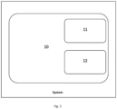
- FIG. 2 illustrates a system.
- the system comprises a crane 10.
- the crane has a jib element 11 and an indicator element 12.
- jib element 11 may be understood broadly. For example a jib element 11 may be moved in a linear or rotational manner. The jib element 11 which is connected to the object or mass to be transported or transferred.
- the indicator element 12 may be designed as an indicator element 12 according to any of the embodiments described above.
- the system may be configured to execute the method described beforehand or any other embodiment or combinations of embodiments described and disclosed in this application.
Landscapes
- Engineering & Computer Science (AREA)
- Mechanical Engineering (AREA)
- Automation & Control Theory (AREA)
- Control And Safety Of Cranes (AREA)
Abstract
A method for operating a crane, comprising the following steps: providing a crane (10) with a jib element (11) and an indicator element (12), wherein the jib element (11) and the indicator element (12) are arranged in a first position; moving the indicator element (12) manually from the first position to a second position; triggering a movement of the jib element (11) from the first position to the second position after the indicator element (12) is arranged in the second position.
Description
- The present invention relates to a method for operating a crane. The present invention further relates to an indicator element, a system with a tower crane or an overhead crane using said method and/or indicator element.
- Cranes are relatively compliant mechanical structures. Especially when moving or when operating a crane in manual or any remote mode configuration, for example when rotating a jib element, this can result in notable oscillations if a human operator directly controls the speed of the motion with an input device. Several techniques exist to filter the user input of the operator such that the flexible modes of the crane are not excited. While this mitigates oscillations, the filtering can introduce significant delay to the user input, which makes the control system unintuitive and difficult to the operator. As a solution, the operator had to anticipate those input delays and had to adapt according to those input delays.
- It has now become apparent, that there is a further need to provide a method for operating a crane.
- In view of the above, it is an object of the present invention to provide a method for operating a crane. It is further an object of the invention to provide an indicator element, a system with a tower crane or an overhead crane using such a method.
- These and other objects, which become apparent upon reading the following description, are solved by the subject matter of the independent claims. The dependent claims refer to preferred embodiments of the invention.
- According to a first aspect of the present disclosure, a method for operating a crane is provided, comprising the following steps: providing a crane with a jib element and an indicator element, wherein the jib element and the indicator element are arranged in a first position. Moving the indicator element from the first position to a second position. Moving the jib element from the first position to the second position, in particular after the indicator element is arranged in the second position.
- The crane may be of any type of cranes. The crane may be for example a construction/tower crane, indoor EOT overhead crane or harbor crane type cranes.
- The jib element may be any element, that needs to be aligned or moved to transport or transfer an object or a mass from the first position to the second position. The jib element is at least indirectly connected to the object or mass to be transported or to be transferred. The jib element may be for example a crane jib, an arm or a movable trolley. The movable trolley may be arranged on a crane jib or may be part of an overhead crane.
- The indicator element may be a visual help to indicate the second position or desired end position of the jib element. The indicator element may also be parameter data, like a distance or an angle to a reference point.
- The method according to the present invention allows the operator to control the indicator element. Once the indicator element has been positioned as desired, i.e. in the second position or the end position, the jib element moves to the second position in a control mode, with tailored controls making sure no oscillations occur. Thereby, cycle time reductions can be achieved, and the crane may be controlled easier by the operator. It may be possible that the jib element starts moving even though the indicator element is not yet in the second position.
- Due to structural compliance, tower cranes can exhibit notable oscillations when rotating the jib element (slew motion). Even if an operator tries to gently ramp up the speed reference using an analog input device (e.g. a joystick), oscillations may occur. It needs a lot of skill and practice for an operator to implicitly learn the compliance of a crane and adapt the input to minimize oscillations. Therefore, the raw user input may be filtered. While such filtering can mitigate the excitation of flexible modes, it inevitably induces delay. Controlling a system with delays may be difficult. If you let go off the input device, it is naturally expected the crane to stop immediately. However, due to the filtering, the crane will keep moving for a while. Again, this unintuitive behavior needs time and practice to get used to. In a way, the problem is shifted from the operator implicitly having to learn the compliant mechanics of the crane to learning the time delays induced by the filtering. While the latter is considered easier, it still requires practice and results in a loss of performance because operators have to act conservatively (e.g. slowly approaching target position to prevent overshoot).
- The method according to the present invention may be an assistive function. This means, the operator stays completely in charge of the crane motion. This means the method does not target any autonomous operation, hence perception and/or safety aspects are no concern. The method may speed up gross positioning of the crane, since optimized trajectory generation and position control may move faster without inducing oscillations compared to human operators, while still giving the operator control for manual fine positioning.
- In an embodiment, the movement of the jib element from the first position to the second position is triggered manually or automatically. Additionally or alternatively, the movement of the indicator element from the first position to the second position is triggered manually or automatically.
- In other words, the jib element may be controlled directly by the operator. Meaning the operator starts the movement of the jib element by manipulating for example a joystick or a similar control device. When manually triggering the movement of the jib element, the jib element and the indicator element preferably move simultaneously at least in partial areas of the movement. This allows the operator to see the second position or stop/end position of the jib element during its movement. The indicator element moves ahead of the jib element to the second position. More precisely, the indicator element may run ahead and the jib element may run behind. The second position of the indicator element is the position where the jib element would come to a standstill if the operator were to interrupt the movement at that time, for example by letting go of the joystick or set the speed reference to zero. In this case, the second position may also be described as dynamic second position. Due to the input filtering, the jib may not come to a stop immediately but may gently ramp down the speed.
- Alternatively, the operator manually triggers the movement of the jib element, after the indicator element is in the second position. Additionally or alternatively, the jib element may be controlled by the operator in a manual mode. Based on a calculated motion profile, which may be generated after the indicator element is in the second position, a graphical display may be employed to visualize the ideal input. The graphical display may be for example shown on a monitor. This provides an assistive tool to the operator, as the operator is provided with an ideal trajectory to track.
- Alternatively, the jib element may be moved automatically based on a calculated motion profile, which may be generated after the indicator element is in the second position. The automatic movement may trigger automatically or manually by the operator after the indicator element is in the second position. The second position may also be a dynamic position. This means, the jib element may start moving although the indicator element has not yet stopped.
- In an embodiment, an acoustic or haptic feedback may be provided while moving the jib element. For a pre-programmed target position, an acoustic signal or haptic feedback via the joystick can be triggered once the operator is moving towards the target and the crane has reached the position from which the crane will converge to the desired target if the user lets go off the input device at the respective time instant. Furthermore, haptic queues in a force-feedback joystick may be employed, indicating if the operator is following the best possible input trajectory.
- In an embodiment, the indicator element is part of the crane or connected to the crane. Preferably, the indicator element is movable, for example linear or rotatable, connected or arranged at the crane. The indicator element may be a constructive part. The indicator element may be a protruding element, for example a web element or a similar hardware element. The indicator element may also be described as a marker element or a pointer element. The indicator element is preferably identifiable or visible when operating the crane. At standstill, the indicator element is parallel to the jib element. While in motion, the indicator element moves ahead or away from the jib element. The indicator element will immediately come to a stop if the operator stops providing input. Next, the jib element follows the movement of the indicator element.
- In an embodiment, the indicator element is a digital and/or virtual indicator element. In other words, the indicator element may be a graphic element, displayed on a monitor, for example of a tablet, or an augmented reality device. For example, a graphical display can show the same as the hardware indicator but as a virtual arrow pointing into the corresponding direction. When the indicator element is provided as a virtual overlay on a graphical display, the position of the real crane may be illustrated with an overlay showing the position of the crane at the predicted stop position. The indicator element may also be provided as a numerical display. This could be for example a simple textual display which may show the predicted extra distance for example in degrees.
- In an embodiment, the indicator element is configured to be seen with an augmented reality device. The operator may use augmented reality glasses with an augmented reality overlay or a similar device to move the indicator device into the second position. More precisely, an operator wearing AR glasses, a virtual overlay of the crane at the predicted stopping position may be superimposed to the real-world view of the actual crane.
- In an embodiment, the automatic movement of the jib element is a controlled movement. In an embodiment, the movement of the jib element comprises an anti-sway control and/or filtering, in particular notch-filtering and/or input shaping. Anti-sway typically refers to load sway. The other aspect is to prevent exciting oscillations of the mechanical structure of the crane. While filtering the input signals, a history of the user inputs is kept track of.. Based on this, the idea is to pre-calculate at every time step where the crane would come to a rest, if the user would let go of the joystick, i.e. produce u(t ≥ Ti ) = 0..
- In case of an abrupt change of speed reference to zero, position remains constant in an unfiltered case. However, such a speed reference profile is prone to significantly excite slew oscillations. The speed does not abruptly change to zero, but the speed references do so in ramped steps, which results in much less slew oscillations being excited. However, this results in unexpected extra travel distance.
- For the special case of switching from maximum/constant speed to zero speed abruptly, the extra travel distance can easily be calculated analytically. In the general case (arbitrary user input, additional rate limiters, etc.), a solution can still be obtained by numerical integration. To this end, a simulation is run at each time step during runtime, piping the history of user inputs from the operator through the input filters and setting all future inputs to zero. The simulation runs until the predicted speed reference becomes zeros (this terminal or final time is known in advance if the filters have a finite time delay, which is the case for input filtering). This way, generic input filtering may be taken into account, including input shapers, notch filters, rate limiters, low-pass filters, etc. By numerical integration of the predicted filtered speed reference, the position of the crane at the end of the prediction is obtained. This corresponds to the stop position, i.e. second position. As the computation of the stop distance is computationally slim, it may be run online. If real-time execution requires, the sampling time of the simulation may be increased. This further speeds up computations at the cost of some loss of precision in the prediction.
- Alternatively, the calculation of the final indicator stop position may also be done with a dynamic model which describes the dynamics of a speed-controlled ideally stiff tower crane. Hence, no structural compliances and no load sway are respected at all. This dynamic model is then fed with the unfiltered user input of the operator. Since the ideally stiff tower crane is speed-controlled and controller dynamics are much faster than tower crane dynamics, the actual slew and trolley positions match instantaneously with the corresponding manual speed references.
- In an embodiment, the movement of the indicator element is a linear or a circular movement. For example the jib element may be of a tower crane or an overhead crane.
- A further aspect of the present invention relates to an indicator element, configured for a use with a crane device, wherein the indicator element is configured to indicate the end position of a movement of a jib element.
- A further aspect of the present invention relates to a system with tower crane or an overhead crane, using the method according to one of the embodiments above.
- The accompanying drawings, which are included to provide a further understanding of the invention and are incorporated in and constitute a part of this application, illustrate an embodiment of the invention and together with the description serve to explain the principle of the invention. The drawings display:
- Figure 1
- a schematic flow diagram of an embodiment of a method; and
- Figure 2
- a schematic illustration of a system.
-
Figure 1 shows an embodiment of a method for operating a crane. In a first step S1, acrane 10 with ajib element 11 and anindicator element 12 is provided. Thejib element 11 and theindicator element 12 are arranged in a first position. The first position may also be described as a start position. - In the next step S2, the
indicator element 11 is moved manually from the first position to a second position. The second position may also be described as end position. - In the next step S3, a movement of the
jib element 11 from the first position to the second position is triggered after theindicator element 12 is arranged in the second position. The different steps may be executed in this order several times afterwards. -
Figure 2 illustrates a system. In the system, a method according to an embodiment of the present invention may be used. The system comprises acrane 10. The crane has ajib element 11 and anindicator element 12. - The term jib element 11may be understood broadly. For example a
jib element 11 may be moved in a linear or rotational manner. Thejib element 11 which is connected to the object or mass to be transported or transferred. - The
indicator element 12 may be designed as anindicator element 12 according to any of the embodiments described above. - The system may be configured to execute the method described beforehand or any other embodiment or combinations of embodiments described and disclosed in this application.
- Any disclosure and embodiments described herein relate to the method for operating a crane and the system, lined out above or below and vice versa. The benefits provided by any of the embodiments and examples equally apply to all other embodiments and examples and vice versa.
- It shall be noted that all embodiments of the present disclosure concerning the method might be carried out with the order of the steps as described. The herein presented method may be carried out with another order of the disclosed steps without departing from the respective method, unless explicitly mentioned to the contrary hereinafter. Furthermore, the features of the independent claims as well as their dependent claims may be combined with each other.
- Other variations to the disclosed embodiments can be understood and effected by those skilled in the art in practicing the claimed invention, from the study of the drawings, the disclosure, and the appended claims. In the claims, the word "comprising" does not exclude other elements or steps and the indefinite article "a" or "an" does not exclude a plurality. The mere fact that certain measures are recited in mutually different dependent claims does not indicate that a combination of these measures cannot be used to advantage. Any reference signs in the claims should not be construed as limiting the scope of the claims.
-
- 10
- crane
- 11
- jib element
- 12
- indicator element
Claims (12)
- A method for operating a crane, comprising the following steps:- providing a crane (10) with a jib element (11) and an indicator element (12), wherein the jib element (11) and the indicator element (12) are arranged in a first position;- moving the indicator element (12) from the first position to a second position;- moving the jib element (11) from the first position to the second position after the indicator element (12) is arranged in the second position.
- The method according to claim 1, wherein the movement of the jib element (11) from the first position to the second position is triggered manually or automatically.
- The method according to claim 1 or 2, wherein the movement of the indicator element from the first position to the second position (12) is triggered manually or automatically.
- The method according to any one of the preceding claims, wherein an acoustic or haptic feedback may be provided while moving the jib element (11) and/or the indicator element (12).
- The method according any one of the preceding claims, wherein the indicator element (12) is part of the crane (10) and/or connected to the crane (10).
- The method according any one of the preceding claims, wherein the indicator element (12) is a digital and/or virtual indicator element (12).
- The method according to any one of the preceding claims, wherein the indicator element (12) is configured to be seen with an augmented reality device.
- The method according to any one of the preceding claims, wherein the movement of the jib element (11) is a controlled movement.
- The method according to any one of the preceding claims, wherein the movement of the jib element (11) comprises an anti-sway control and/or filtering.
- The method according to any one of the preceding claims, wherein the movement of the indicator element (12) is a linear or a circular movement.
- An indicator element, configured for a use with a crane device, wherein the indicator element (12) is configured to indicate an end position of a movement of a jib element (11).
- A system comprising a tower crane or overhead crane, using the method according to anyone of the claims 1 to 10 and/or an indicator element according to claim 11.
Priority Applications (3)
| Application Number | Priority Date | Filing Date | Title |
|---|---|---|---|
| EP23167822.8A EP4446273A1 (en) | 2023-04-13 | 2023-04-13 | Method for operating a crane, indicator element and a system |
| CN202410413628.8A CN118790890A (en) | 2023-04-13 | 2024-04-08 | Method, indicator element and system for operating a crane |
| US18/630,116 US20240343528A1 (en) | 2023-04-13 | 2024-04-09 | Method for Operating a Crane, Indicator Element and a System |
Applications Claiming Priority (1)
| Application Number | Priority Date | Filing Date | Title |
|---|---|---|---|
| EP23167822.8A EP4446273A1 (en) | 2023-04-13 | 2023-04-13 | Method for operating a crane, indicator element and a system |
Publications (1)
| Publication Number | Publication Date |
|---|---|
| EP4446273A1 true EP4446273A1 (en) | 2024-10-16 |
Family
ID=86007673
Family Applications (1)
| Application Number | Title | Priority Date | Filing Date |
|---|---|---|---|
| EP23167822.8A Pending EP4446273A1 (en) | 2023-04-13 | 2023-04-13 | Method for operating a crane, indicator element and a system |
Country Status (3)
| Country | Link |
|---|---|
| US (1) | US20240343528A1 (en) |
| EP (1) | EP4446273A1 (en) |
| CN (1) | CN118790890A (en) |
Citations (4)
| Publication number | Priority date | Publication date | Assignee | Title |
|---|---|---|---|---|
| WO2017032922A1 (en) * | 2015-08-21 | 2017-03-02 | Konecranes Global Oy | Controlling of lifting device |
| WO2019229751A1 (en) * | 2018-05-30 | 2019-12-05 | Syracuse Ltd. | System and method for transporting a swaying hoisted load |
| DE102018218728A1 (en) * | 2018-10-31 | 2020-04-30 | Brendel Holding Gmbh & Co. Kg | System for controlling a machine with a "wearable display" |
| EP3660231A1 (en) * | 2018-11-08 | 2020-06-03 | Intsite Ltd | System and method for autonomous operation of heavy machinery |
-
2023
- 2023-04-13 EP EP23167822.8A patent/EP4446273A1/en active Pending
-
2024
- 2024-04-08 CN CN202410413628.8A patent/CN118790890A/en active Pending
- 2024-04-09 US US18/630,116 patent/US20240343528A1/en active Pending
Patent Citations (4)
| Publication number | Priority date | Publication date | Assignee | Title |
|---|---|---|---|---|
| WO2017032922A1 (en) * | 2015-08-21 | 2017-03-02 | Konecranes Global Oy | Controlling of lifting device |
| WO2019229751A1 (en) * | 2018-05-30 | 2019-12-05 | Syracuse Ltd. | System and method for transporting a swaying hoisted load |
| DE102018218728A1 (en) * | 2018-10-31 | 2020-04-30 | Brendel Holding Gmbh & Co. Kg | System for controlling a machine with a "wearable display" |
| EP3660231A1 (en) * | 2018-11-08 | 2020-06-03 | Intsite Ltd | System and method for autonomous operation of heavy machinery |
Also Published As
| Publication number | Publication date |
|---|---|
| US20240343528A1 (en) | 2024-10-17 |
| CN118790890A (en) | 2024-10-18 |
Similar Documents
| Publication | Publication Date | Title |
|---|---|---|
| US10252424B2 (en) | Systems and methods for control of robotic manipulation | |
| CN108025896B (en) | Control of a lifting device | |
| JP6684442B2 (en) | Control method and control device for suspension crane | |
| CN104176242B (en) | Flight control and control method | |
| CN101384974B (en) | Method and system for assisting in piloting an aircraft | |
| JP6038189B2 (en) | Synchronous control device | |
| CN112943751B (en) | Auxiliary job control method, device, electronic equipment and storage medium | |
| CN117864959A (en) | A hoisting posture control system and control method | |
| EP3804919B1 (en) | Robot system and robot control method | |
| TWI632768B (en) | Motor control device | |
| WO2021131136A1 (en) | Remote control system for construction machine | |
| EP4446273A1 (en) | Method for operating a crane, indicator element and a system | |
| KR20180070491A (en) | A flight control method for rotorcraft, and a rotorcraft | |
| JPWO2021177052A5 (en) | ||
| CN104261257B (en) | Speed regulation method, device and system for tower crane | |
| JPH08504543A (en) | Camera control method and apparatus | |
| KR20080040624A (en) | Shaping controller with combined feedback and command for multi-state control applied to improve positioning in cranes and reduce cable shake | |
| CN107553485A (en) | The generation method of dynamic virtual fixture in a kind of interactive process | |
| US10289074B2 (en) | Controller including means for confirmation in preparation of synchronous operation teaching data | |
| JPH03292987A (en) | Stage setting controller | |
| CN112518777A (en) | Robot control device | |
| Chakraborty et al. | Saving time by tip control & automation of knuckle and boom hydraulic crane | |
| JPH02185379A (en) | Manipulator device | |
| JP2019101893A (en) | Drive control device, drive device, and assist control device | |
| JPS63312432A (en) | Controller for braking of slewing body |
Legal Events
| Date | Code | Title | Description |
|---|---|---|---|
| PUAI | Public reference made under article 153(3) epc to a published international application that has entered the european phase |
Free format text: ORIGINAL CODE: 0009012 |
|
| STAA | Information on the status of an ep patent application or granted ep patent |
Free format text: STATUS: THE APPLICATION HAS BEEN PUBLISHED |
|
| AK | Designated contracting states |
Kind code of ref document: A1 Designated state(s): AL AT BE BG CH CY CZ DE DK EE ES FI FR GB GR HR HU IE IS IT LI LT LU LV MC ME MK MT NL NO PL PT RO RS SE SI SK SM TR |
|
| STAA | Information on the status of an ep patent application or granted ep patent |
Free format text: STATUS: REQUEST FOR EXAMINATION WAS MADE |
|
| 17P | Request for examination filed |
Effective date: 20250217 |