EP4446266A1 - Conveyor and image forming apparatus - Google Patents
Conveyor and image forming apparatus Download PDFInfo
- Publication number
- EP4446266A1 EP4446266A1 EP24167129.6A EP24167129A EP4446266A1 EP 4446266 A1 EP4446266 A1 EP 4446266A1 EP 24167129 A EP24167129 A EP 24167129A EP 4446266 A1 EP4446266 A1 EP 4446266A1
- Authority
- EP
- European Patent Office
- Prior art keywords
- roller
- rollers
- sheet
- conveying rollers
- conveyance direction
- Prior art date
- Legal status (The legal status is an assumption and is not a legal conclusion. Google has not performed a legal analysis and makes no representation as to the accuracy of the status listed.)
- Pending
Links
- 239000007788 liquid Substances 0.000 claims description 4
- 238000007639 printing Methods 0.000 description 15
- 238000005299 abrasion Methods 0.000 description 13
- 238000011144 upstream manufacturing Methods 0.000 description 11
- 238000007641 inkjet printing Methods 0.000 description 9
- 230000006866 deterioration Effects 0.000 description 5
- 210000000078 claw Anatomy 0.000 description 4
- 230000015572 biosynthetic process Effects 0.000 description 3
- 230000000052 comparative effect Effects 0.000 description 3
- 238000000034 method Methods 0.000 description 3
- 230000004323 axial length Effects 0.000 description 2
- 238000012986 modification Methods 0.000 description 2
- 230000004048 modification Effects 0.000 description 2
- 238000003491 array Methods 0.000 description 1
- 239000003086 colorant Substances 0.000 description 1
- 230000000694 effects Effects 0.000 description 1
- 230000002093 peripheral effect Effects 0.000 description 1
- 230000001360 synchronised effect Effects 0.000 description 1
Images




Classifications
-
- B—PERFORMING OPERATIONS; TRANSPORTING
- B65—CONVEYING; PACKING; STORING; HANDLING THIN OR FILAMENTARY MATERIAL
- B65H—HANDLING THIN OR FILAMENTARY MATERIAL, e.g. SHEETS, WEBS, CABLES
- B65H5/00—Feeding articles separated from piles; Feeding articles to machines
- B65H5/06—Feeding articles separated from piles; Feeding articles to machines by rollers or balls, e.g. between rollers
- B65H5/062—Feeding articles separated from piles; Feeding articles to machines by rollers or balls, e.g. between rollers between rollers or balls
-
- B—PERFORMING OPERATIONS; TRANSPORTING
- B65—CONVEYING; PACKING; STORING; HANDLING THIN OR FILAMENTARY MATERIAL
- B65H—HANDLING THIN OR FILAMENTARY MATERIAL, e.g. SHEETS, WEBS, CABLES
- B65H5/00—Feeding articles separated from piles; Feeding articles to machines
- B65H5/06—Feeding articles separated from piles; Feeding articles to machines by rollers or balls, e.g. between rollers
- B65H5/068—Feeding articles separated from piles; Feeding articles to machines by rollers or balls, e.g. between rollers between one or more rollers or balls and stationary pressing, supporting or guiding elements
-
- B—PERFORMING OPERATIONS; TRANSPORTING
- B41—PRINTING; LINING MACHINES; TYPEWRITERS; STAMPS
- B41J—TYPEWRITERS; SELECTIVE PRINTING MECHANISMS, i.e. MECHANISMS PRINTING OTHERWISE THAN FROM A FORME; CORRECTION OF TYPOGRAPHICAL ERRORS
- B41J13/00—Devices or arrangements of selective printing mechanisms, e.g. ink-jet printers or thermal printers, specially adapted for supporting or handling copy material in short lengths, e.g. sheets
- B41J13/02—Rollers
- B41J13/03—Rollers driven, e.g. feed rollers separate from platen
-
- B—PERFORMING OPERATIONS; TRANSPORTING
- B41—PRINTING; LINING MACHINES; TYPEWRITERS; STAMPS
- B41J—TYPEWRITERS; SELECTIVE PRINTING MECHANISMS, i.e. MECHANISMS PRINTING OTHERWISE THAN FROM A FORME; CORRECTION OF TYPOGRAPHICAL ERRORS
- B41J13/00—Devices or arrangements of selective printing mechanisms, e.g. ink-jet printers or thermal printers, specially adapted for supporting or handling copy material in short lengths, e.g. sheets
- B41J13/02—Rollers
- B41J13/076—Construction of rollers; Bearings therefor
-
- B—PERFORMING OPERATIONS; TRANSPORTING
- B65—CONVEYING; PACKING; STORING; HANDLING THIN OR FILAMENTARY MATERIAL
- B65H—HANDLING THIN OR FILAMENTARY MATERIAL, e.g. SHEETS, WEBS, CABLES
- B65H2404/00—Parts for transporting or guiding the handled material
- B65H2404/10—Rollers
- B65H2404/11—Details of cross-section or profile
- B65H2404/114—Built-up elements
-
- B—PERFORMING OPERATIONS; TRANSPORTING
- B65—CONVEYING; PACKING; STORING; HANDLING THIN OR FILAMENTARY MATERIAL
- B65H—HANDLING THIN OR FILAMENTARY MATERIAL, e.g. SHEETS, WEBS, CABLES
- B65H2404/00—Parts for transporting or guiding the handled material
- B65H2404/10—Rollers
- B65H2404/15—Roller assembly, particular roller arrangement
- B65H2404/154—Rollers conveyor
- B65H2404/1542—Details of pattern of rollers
-
- B—PERFORMING OPERATIONS; TRANSPORTING
- B65—CONVEYING; PACKING; STORING; HANDLING THIN OR FILAMENTARY MATERIAL
- B65H—HANDLING THIN OR FILAMENTARY MATERIAL, e.g. SHEETS, WEBS, CABLES
- B65H2404/00—Parts for transporting or guiding the handled material
- B65H2404/10—Rollers
- B65H2404/19—Other features of rollers
-
- B—PERFORMING OPERATIONS; TRANSPORTING
- B65—CONVEYING; PACKING; STORING; HANDLING THIN OR FILAMENTARY MATERIAL
- B65H—HANDLING THIN OR FILAMENTARY MATERIAL, e.g. SHEETS, WEBS, CABLES
- B65H2404/00—Parts for transporting or guiding the handled material
- B65H2404/50—Surface of the elements in contact with the forwarded or guided material
- B65H2404/53—Surface of the elements in contact with the forwarded or guided material with particular mechanical, physical properties
- B65H2404/532—Surface of the elements in contact with the forwarded or guided material with particular mechanical, physical properties with particular durometer
- B65H2404/5322—Surface of the elements in contact with the forwarded or guided material with particular mechanical, physical properties with particular durometer surface with different hardness
-
- B—PERFORMING OPERATIONS; TRANSPORTING
- B65—CONVEYING; PACKING; STORING; HANDLING THIN OR FILAMENTARY MATERIAL
- B65H—HANDLING THIN OR FILAMENTARY MATERIAL, e.g. SHEETS, WEBS, CABLES
- B65H2601/00—Problem to be solved or advantage achieved
- B65H2601/20—Avoiding or preventing undesirable effects
- B65H2601/25—Damages to handled material
- B65H2601/251—Smearing
-
- B—PERFORMING OPERATIONS; TRANSPORTING
- B65—CONVEYING; PACKING; STORING; HANDLING THIN OR FILAMENTARY MATERIAL
- B65H—HANDLING THIN OR FILAMENTARY MATERIAL, e.g. SHEETS, WEBS, CABLES
- B65H2601/00—Problem to be solved or advantage achieved
- B65H2601/20—Avoiding or preventing undesirable effects
- B65H2601/25—Damages to handled material
- B65H2601/254—Permanent deformation
-
- B—PERFORMING OPERATIONS; TRANSPORTING
- B65—CONVEYING; PACKING; STORING; HANDLING THIN OR FILAMENTARY MATERIAL
- B65H—HANDLING THIN OR FILAMENTARY MATERIAL, e.g. SHEETS, WEBS, CABLES
- B65H2801/00—Application field
- B65H2801/03—Image reproduction devices
- B65H2801/06—Office-type machines, e.g. photocopiers
Definitions
- the present embodiment relates to a recording medium conveyor and an image forming apparatus and particularly relates to a recording medium conveyor including multiple rollers disposed dispersive to inhibit the surface of a sheet-shaped medium from having roller abrasions and an image forming apparatus including the recording medium conveyor.
- an inkjet image forming apparatus that includes a recording head serving as a liquid discharge head that discharges droplets of recording liquid and causes, while conveying a sheet-shaped recording medium, droplets of recording liquid to be adhered to the recording medium to perform printing.
- a recording head serving as a liquid discharge head that discharges droplets of recording liquid and causes, while conveying a sheet-shaped recording medium, droplets of recording liquid to be adhered to the recording medium to perform printing.
- Such an image forming apparatus includes multiple rollers for flat conveyance or curved conveyance of a sheet-shaped recording medium.
- Such multiple rollers is disposed in multiple lines along a conveyance direction, such as flat conveyance and curved conveyance.
- a conveyance direction such as flat conveyance and curved conveyance.
- a recording medium in response to slipping of the multiple rollers on the same straight line, a recording medium has belt-like overlaid abrasions thereon. If a recording medium has its surface abraded, as a disadvantage, an image formed on the surface by inkjetting on the downstream side in the conveyance direction is low in quality (belt-like unusual image).
- a conveyor includes multiple conveying rollers to convey a sheet in a conveyance direction, and the multiple conveying rollers: arranged in the conveyance direction; and shifted with each other in a width direction orthogonal to the conveyance direction.
- FIG. 1 is a schematic view of an inkjet printing machine, to which an inkjet printing method is applied, according to an embodiment of the present embodiment.
- An inkjet printer 1 as an inkjet printing machine includes a sheet feeder 2 that houses sheets (recording sheets) P, a manual sheet feeder 3, a sheet ejection tray 4, and a duplex printing unit 5.
- a feeding roller 10 separates a sheet P from the sheets P housed in the sheet feeder 2 to convey the sheet P upward in FIG. 1 .
- the sheet P stops temporarily at the position of a registration sensor 9, and a registration roller 18 aligns the leading end (upper end) of the sheet P. Then, the registration roller 18 starts to feed the sheet P at a predetermined timing synchronized with the timing of output of image data.
- the sheet P After reaching a conveying belt 13, the sheet P is further conveyed leftward in FIG. 1 by the conveying belt 13 in a conveyance direction. Then, heads 6 respectively provided with colors of: cyan, yellow, magenta, and black to perform printing on the sheet P on a flat portion (flat conveyance path) of the conveying belt 13.
- a switching claw 8 makes a switch between a path to the sheet ejection tray 4 and a path to the duplex printing unit 5.
- the switching claw 8 is set to the solid-line side, so that the sheet P is fed to ejecting rollers 15 and then is ejected to the sheet ejection tray 4 in an inverted manner.
- the switching claw 8 is set to the broken-line side.
- the sheet P After fed to inverting rollers 16, the sheet P returns to invert. Furthermore, the sheet P travels on the path, through duplex feeding rollers 17 and a vertically conveying roller 12, inside the duplex printing unit 5 and then is fed upward in FIG. 1 by the registration roller 18, again. Then, an image is formed on the back face of the sheet P in accordance with a procedure similar to the procedure of formation of the image on the front face.
- the switching claw 8 After formation of the image on the back face of the sheet P, the switching claw 8 is set to the solid-line side, so that the sheet P is fed to the ejecting rollers 15 and then is ejected to the sheet ejection tray 4.
- a manual feeding roller 11 a large-capacity ink cartridge 20, and a sub-tank 21 are provided. Ink is fed from the large-capacity ink cartridge 20 to the sub-tank 21 by an ink supply pump.
- FIG. 2A is a schematic perspective view of a recording medium conveyor according to the present embodiment.
- FIG. 2B is a schematic perspective view of a recording medium conveyor according to a comparative example.
- FIGS. 2A and 2B each illustrate a state of conveyance of a sheet P as a sheet-shaped recording medium from right to left by multiple roller shafts S1 to S5.
- roller shafts S1 to S5 are disposed at substantially regular intervals in this order from the upstream side in a conveyance direction.
- the roller shafts S1 to S5 each have its axis orthogonal to the conveyance direction of the sheet P and parallel to the width direction of the sheet P.
- the roller shafts S1 to S5 are each driven by a drive including a motor and gears such that the roller shafts S1 to S5 rotate in the same direction.
- the roller shafts S1 to S5 each have multiple rollers R as conveying rollers attached thereto.
- the multiple rollers R can be made identical in diameter and in size (axial length) or can be made different in diameter and in axial length.
- a left roller R11 and a right roller R12 are attached as a lateral pair to the most upstream roller shaft S1.
- the left roller R11 and the right roller R12 are bilaterally symmetrical about the central line CL of the sheet P.
- a left roller R21 and a right roller R22 are attached as a lateral pair to the roller shaft S2 downstream of the roller shaft S1.
- the left roller R21 and the right roller R22 are bilaterally symmetrical about the central line of the sheet P.
- the rollers R21 and R22 are located, in terms of axial direction, adjacently to the rollers R11 and R12 inside the rollers R11 and R12 upstream of and closest to the rollers R21 and R22, respectively.
- a left roller R31 and a right roller R32 are attached as a lateral pair to the roller shaft S3 downstream of the roller shaft S2 (intermediate in the conveyance direction).
- the left roller R31 and the right roller R32 are bilaterally symmetrical about the central line of the sheet P.
- the rollers R31 and R32 are located, in terms of axial direction, adjacently to the rollers R21 and R22 inside the rollers R21 and R22 upstream of and closest to the rollers R31 and R32, respectively.
- Left rollers R41 and R42 and right rollers R43 and R44 are attached as a lateral pair to the roller shaft S4 downstream of the roller shaft S3.
- the left rollers R41 and R42 and the right rollers R43 and R44 are bilaterally symmetrical about the central line of the sheet P.
- the inner rollers R42 and R43 are located adjacently to the rollers R31 and R32 inside the rollers R31 and R32 upstream of and closest to the rollers R42 and R43, respectively.
- the outer rollers R41 and R44 are spaced by one roller outside the most upstream rollers R11 and R12, respectively.
- Left rollers R51 and R52 and right rollers R53 and R54 are attached as a lateral pair to the most downstream roller shaft S5.
- the left rollers R51 and R52 and the right rollers R53 and R54 are bilaterally symmetrical about the central line of the sheet P.
- the inner rollers R52 and R53 are located adjacently to the rollers R42 and R43 inside the rollers R42 and R43 upstream of and closest to the rollers R52 and R53, respectively.
- the outer roller R51 is located in a space for one roller between the rollers R11 and R41, and the outer roller R54 is located in a space for one roller between the rollers R12 and R44.
- the rollers R11 to R54 as the rollers R in FIG. 2A are each located on any of the multiple roller shafts S1 to S5 such that the locations of the rollers R11 to R54 are different in terms of axial direction. Therefore, even if the sheet P has abrasions t due to the rollers R11 to R54, the abrasions t are distributed in the width direction of the sheet P without mutual overlapping (mutual overlaying). Thus, in a case where an image is formed, by inkjetting, on the sheet P downstream of the rollers R11 to R54, the image has no deterioration in quality (no belt-shaped unusual image) even with the abrasions t.
- the recording medium conveyor in FIG. 2B according to the comparative example includes five left rollers R11, R21, R31, R41, and R51 as a straight roller array in the conveyance direction and five right rollers R12, R22, R32, R42, and R52 as a straight roller array in the conveyance direction.
- respective abrasions due to the rollers in each of the left and right roller arrays tend to be overlapped (overlaid), leading to formation of a severe roller abrasion T on the sheet P.
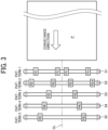
- FIG. 3 illustrates a recording medium conveyor according to an embodiment of the present embodiment.
- Five roller shafts S1 to S5 disposed in this order from the upstream side in the conveyance direction have respective different roller arrangement patterns 1 to 5.
- roller arrangement patterns 1 to 5 are not necessarily provided all together. Provided may be a conveyor with any two, any three, or any four of the roller arrangement patterns 1 to 5.
- Upper rollers R12, R22, R31, R41, and R51 are disposed like steps gradually away from the central line CL of a sheet P.
- Lower rollers R13, R23, R32, R42, and R52 are disposed like steps gradually away from the central line CL of the sheet P.
- rollers R11 and R21 are disposed like steps gradually away from the central line CL of the sheet P
- lower rollers R14 and R24 are disposed like steps gradually away from the central line CL of the sheet P. That is, such rollers R are disposed without any overlapping when viewed in the conveyance direction. Therefore, in a case where an image is formed, by inkjetting, on the sheet P downstream of the rollers R11 to R52, the image has a minimum deterioration in quality even with any roller abrasion (minimum belt-shaped unusual image).
- roller arrangement patterns 1 to 5 are not necessarily limited to the order in FIG. 3 .
- the patterns 1 to 5 may be disposed in this order from the downstream side or may be disposed in the order of the patterns 3, 4, 5, 1, and 2 from the upstream side. Alternatively, the patterns 1 to 5 may be disposed in any order.
- the conveyor includes multiple conveying rollers (R) to convey a sheet in a conveyance direction, and the multiple conveying rollers: arranged in the conveyance direction; and shifted with each other in a width direction orthogonal to the conveyance direction.
- the conveyor includes multiple roller shafts (S1 to S5): arrayed in the conveyance direction; and each having axis extending in the width direction, wherein the multiple roller shafts (S1 to S5) respectively support the multiple conveying rollers (R) arranged on the multiple roller shafts (S1 to S5) with different arrangement patterns of the multiple conveying rollers (R) on the multiple roller shafts (S1 to S5).
- the conveyor includes multiple roller shafts (S1 to S5): arrayed in the conveyance direction; and each having axis extending in the width direction, wherein the multiple roller shafts (S1 to S5) respectively support the multiple conveying rollers (R) arranged on the multiple roller shafts (S1 to S5) with different arrangement patterns of the multiple conveying rollers (R) on the multiple roller shafts (S1 to S5).
- Each of the multiple roller shafts (S1 to S5) has two or more conveying rollers (R), and a distance between the two or more rollers are gradually increased in the conveyance direction.
- FIG. 4A is a schematic plan view of a recording medium conveyor according to an embodiment for flat conveyance.
- FIG. 4B is a schematic cross-sectional view of the recording medium conveyor.
- the roller arrangement pattern in FIG. 4A is similar to the roller arrangement pattern in FIG. 3 .
- the flat conveyance in FIGS. 4A and 4B corresponds, for example, to flat conveyance due to the vertically conveying roller 12 in FIG. 1 .
- guides G1 and G2 are disposed, respectively, on the upper side and lower side of a sheet P.
- the guides G1 and G2 each have a cutout through which a conveying roller protrudes inward.
- the guides G1 and G2 form a flat conveyance path along which the sheet P is conveyed in the flat conveyance.
- a hard roller Rh and a soft roller Rs are provided, respectively, as the upper conveying roller (conveying roller on the printing side) and the lower conveying roller.
- the sheet P receives more severe abrasion damage from the soft roller Rs than from the hard roller Rh.
- the soft roller Rs is disposed on the non-printing side (lower side) to inhibit a deterioration in the quality of an image (belt-shaped unusual image).
- Each of the multiple conveying rollers includes a pair of: a first roller (hard roller Rh) having a first hardness; and a second roller (soft roller Rs) having a second hardness softer than the first hardness.
- the first roller faces a first face of the sheet facing the head 6, and the second roller faces a second face opposite to the first face of the sheet P.
- FIG. 5A is a schematic plan view of a recording medium conveyor according to an embodiment for curved conveyance.
- FIG. 5B is a schematic cross-sectional view of the recording medium conveyor.
- the roller arrangement pattern in FIG. 5A includes the patterns 1 and 2 in FIG. 3 .
- a gradually broadened roller arrangement based on the patterns 1 and 2 enables obtainment of a function of stretching a sheet P in its width direction (in the up-down direction in FIG. 5A ).
- Such stretching the sheet P in its wide direction as above enables an improvement in the quality of image forming by inkjetting.
- the curved conveyance in FIGS. 5A and 5B corresponds, for example, to curved conveyance due to a duplex feeding roller 17 in FIG. 1 .
- guides G1 and G2 are disposed inside and outside the sheet P having a curvature.
- the guides G1 and G2 each have a cutout through which a conveying roller protrudes to the sheet P.
- the guides G1 and G2 form a curved conveyance path along which the sheet P is conveyed in the curved conveyance.
- a hard roller Rh and a soft roller Rs are provided, respectively, as the inner conveying roller (conveying roller on the printing side) and the outer conveying roller.
- the sheet P receives more severe abrasion damage from the soft roller Rs than from the hard roller Rh.
- the soft roller Rs is disposed on the non-printing side (outer side) to inhibit a deterioration in the quality of an image (belt-shaped unusual image).
- Such a conveying roller arrangement pattern as described above can be achieved with at least three rollers.
- such a conveying roller arrangement pattern as described above can be achieved with three rollers R that are two rollers on the upstream side in the conveyance direction and a single roller on the downstream side in the conveyance direction.
- Such a conveying roller arrangement pattern as described above can be achieved with three rollers R that are a single roller on the upstream side in the conveyance direction and two rollers on the downstream side in the conveyance direction. Then, the two rollers are disposed on both sides in the width direction of a recording medium.
- additional rollers may be appropriately provided to the roller shafts thereof or a roller shaft different from the roller shafts.
- the present embodiment is not limited to an inkjet image forming apparatus and thus can be applied to an electrophotographic image forming apparatus or a recording medium conveyor therefor.
- the conveyor may include a flat conveyance path, and the multiple conveying rollers include three or more rollers to convey the sheet along the flat conveyance path.
- the conveyor may include a curved conveyance path, and the multiple conveying rollers include three or more conveying rollers to convey the sheet along the curved conveyance path.
- a recording medium can be inhibited from having overlaid roller abrasions for an improvement in the quality of an image.
- a recording medium conveyor includes multiple conveying rollers disposed in a conveyance direction of a sheet-shaped recording medium, the multiple conveying rollers not overlapping each other in the conveyance direction of the sheet-shaped recording medium.
- the recording medium conveyor of Aspect 1 further includes multiple roller shafts disposed in the conveyance direction, the multiple roller shafts having respective axes extending in a width direction of the sheet-shaped recording medium orthogonal to the conveyance direction, in which the multiple conveying rollers is supported by the multiple roller shafts in different arrangement patterns.
- the multiple conveying rollers includes a pair of a hard roller and a soft roller different in hardness.
- the hard roller is disposed on a side of location of a face for printing of the sheet-shaped recording medium and the soft roller is disposed on a side of location of a face for non-printing of the sheet-shaped recording medium.
- the multiple conveying rollers includes three conveying rollers configured to bring the sheet-shaped recording medium in flat conveyance.
- the multiple conveying rollers includes three conveying rollers configured to bring the sheet-shaped recording medium in curved conveyance.
- an image forming apparatus includes the recording medium conveyor of any one of Aspects 1 to 6.
Landscapes
- Engineering & Computer Science (AREA)
- Mechanical Engineering (AREA)
- Delivering By Means Of Belts And Rollers (AREA)
Abstract
A conveyor includes multiple conveying rollers (R) to convey a sheet in a conveyance direction, and the multiple conveying rollers: arranged in the conveyance direction; and shifted with each other in a width direction orthogonal to the conveyance direction.
Description
- The present embodiment relates to a recording medium conveyor and an image forming apparatus and particularly relates to a recording medium conveyor including multiple rollers disposed dispersive to inhibit the surface of a sheet-shaped medium from having roller abrasions and an image forming apparatus including the recording medium conveyor.
- As an exemplary image forming apparatus, such as a printer, a facsimile machine, a copier, or a multifunction peripheral, there is an inkjet image forming apparatus that includes a recording head serving as a liquid discharge head that discharges droplets of recording liquid and causes, while conveying a sheet-shaped recording medium, droplets of recording liquid to be adhered to the recording medium to perform printing. Such an image forming apparatus includes multiple rollers for flat conveyance or curved conveyance of a sheet-shaped recording medium.
- Such multiple rollers is disposed in multiple lines along a conveyance direction, such as flat conveyance and curved conveyance. In a case where multiple rollers is located on the same straight line in the conveyance direction, in response to slipping of the multiple rollers on the same straight line, a recording medium has belt-like overlaid abrasions thereon. If a recording medium has its surface abraded, as a disadvantage, an image formed on the surface by inkjetting on the downstream side in the conveyance direction is low in quality (belt-like unusual image).
- In an aspect of the present disclosure, a conveyor includes multiple conveying rollers to convey a sheet in a conveyance direction, and the multiple conveying rollers: arranged in the conveyance direction; and shifted with each other in a width direction orthogonal to the conveyance direction.
- A more complete appreciation of embodiments of the present disclosure and many of the attendant advantages and features thereof can be readily obtained and understood from the following detailed description with reference to the accompanying drawings, wherein:
-
FIG. 1 is a schematic view of the configuration of an inkjet image forming apparatus according to an embodiment of the present embodiment; -
FIG. 2A is a schematic perspective view of a recording medium conveyor according to the present embodiment; -
FIG. 2B is a schematic perspective view of a recording medium conveyor according to a comparative example; -
FIG. 3 is a schematic plan view of a recording medium conveyor according to an embodiment of the present embodiment; -
FIG. 4A is a schematic plan view of a recording medium conveyor according to an embodiment for flat conveyance; -
FIG. 4B is a schematic cross-sectional view of the recording medium conveyor; -
FIG. 5A is a schematic plan view of a recording medium conveyor according to an embodiment for curved conveyance; and -
FIG. 5B is a schematic cross-sectional view of the recording medium conveyor. - The accompanying drawings are intended to depict embodiments of the present disclosure and should not be interpreted to limit the scope thereof. The accompanying drawings are not to be considered as drawn to scale unless explicitly noted. Also, identical or similar reference numerals designate identical or similar components throughout the several views.
- In describing embodiments illustrated in the drawings, specific terminology is employed for the sake of clarity. However, the disclosure of this specification is not intended to be limited to the specific terminology so selected and it is to be understood that each specific element includes all technical equivalents that have a similar function, operate in a similar manner, and achieve a similar result.
- Referring now to the drawings, embodiments of the present disclosure are described below. As used herein, the singular forms "a," "an," and "the" are intended to include the plural forms as well, unless the context clearly indicates otherwise.
- Embodiments of the present embodiment will be described below with reference to the drawings.
FIG. 1 is a schematic view of an inkjet printing machine, to which an inkjet printing method is applied, according to an embodiment of the present embodiment. Aninkjet printer 1 as an inkjet printing machine includes asheet feeder 2 that houses sheets (recording sheets) P, amanual sheet feeder 3, asheet ejection tray 4, and aduplex printing unit 5. In response to a printing request from an external personal computer (PC) connected through a network, afeeding roller 10 separates a sheet P from the sheets P housed in thesheet feeder 2 to convey the sheet P upward inFIG. 1 . - The sheet P stops temporarily at the position of a
registration sensor 9, and aregistration roller 18 aligns the leading end (upper end) of the sheet P. Then, theregistration roller 18 starts to feed the sheet P at a predetermined timing synchronized with the timing of output of image data. After reaching aconveying belt 13, the sheet P is further conveyed leftward inFIG. 1 by theconveying belt 13 in a conveyance direction. Then,heads 6 respectively provided with colors of: cyan, yellow, magenta, and black to perform printing on the sheet P on a flat portion (flat conveyance path) of theconveying belt 13. - The sheet P after printing is conveyed by
spur gears 14a and horizontally conveyingrollers 14b in the conveyance direction. After the elapse of time necessary to dry the ink, a switchingclaw 8 makes a switch between a path to thesheet ejection tray 4 and a path to theduplex printing unit 5. For single-sided printing, theswitching claw 8 is set to the solid-line side, so that the sheet P is fed to ejectingrollers 15 and then is ejected to thesheet ejection tray 4 in an inverted manner. - For double-sided printing, the switching
claw 8 is set to the broken-line side. Thus, after fed to invertingrollers 16, the sheet P returns to invert. Furthermore, the sheet P travels on the path, throughduplex feeding rollers 17 and a vertically conveyingroller 12, inside theduplex printing unit 5 and then is fed upward inFIG. 1 by theregistration roller 18, again. Then, an image is formed on the back face of the sheet P in accordance with a procedure similar to the procedure of formation of the image on the front face. - After formation of the image on the back face of the sheet P, the
switching claw 8 is set to the solid-line side, so that the sheet P is fed to theejecting rollers 15 and then is ejected to thesheet ejection tray 4. Note that, referring toFIG. 1 , amanual feeding roller 11, a large-capacity ink cartridge 20, and asub-tank 21 are provided. Ink is fed from the large-capacity ink cartridge 20 to thesub-tank 21 by an ink supply pump. -
FIG. 2A is a schematic perspective view of a recording medium conveyor according to the present embodiment.FIG. 2B is a schematic perspective view of a recording medium conveyor according to a comparative example.FIGS. 2A and 2B each illustrate a state of conveyance of a sheet P as a sheet-shaped recording medium from right to left by multiple roller shafts S1 to S5. - The roller shafts S1 to S5 are disposed at substantially regular intervals in this order from the upstream side in a conveyance direction.
- The roller shafts S1 to S5 each have its axis orthogonal to the conveyance direction of the sheet P and parallel to the width direction of the sheet P. The roller shafts S1 to S5 are each driven by a drive including a motor and gears such that the roller shafts S1 to S5 rotate in the same direction.
- The roller shafts S1 to S5 each have multiple rollers R as conveying rollers attached thereto. The multiple rollers R can be made identical in diameter and in size (axial length) or can be made different in diameter and in axial length.
- A left roller R11 and a right roller R12 are attached as a lateral pair to the most upstream roller shaft S1. The left roller R11 and the right roller R12 are bilaterally symmetrical about the central line CL of the sheet P.
- A left roller R21 and a right roller R22 are attached as a lateral pair to the roller shaft S2 downstream of the roller shaft S1. The left roller R21 and the right roller R22 are bilaterally symmetrical about the central line of the sheet P. The rollers R21 and R22 are located, in terms of axial direction, adjacently to the rollers R11 and R12 inside the rollers R11 and R12 upstream of and closest to the rollers R21 and R22, respectively.
- A left roller R31 and a right roller R32 are attached as a lateral pair to the roller shaft S3 downstream of the roller shaft S2 (intermediate in the conveyance direction). The left roller R31 and the right roller R32 are bilaterally symmetrical about the central line of the sheet P. The rollers R31 and R32 are located, in terms of axial direction, adjacently to the rollers R21 and R22 inside the rollers R21 and R22 upstream of and closest to the rollers R31 and R32, respectively.
- Left rollers R41 and R42 and right rollers R43 and R44 are attached as a lateral pair to the roller shaft S4 downstream of the roller shaft S3. The left rollers R41 and R42 and the right rollers R43 and R44 are bilaterally symmetrical about the central line of the sheet P.
- The inner rollers R42 and R43 are located adjacently to the rollers R31 and R32 inside the rollers R31 and R32 upstream of and closest to the rollers R42 and R43, respectively. The outer rollers R41 and R44 are spaced by one roller outside the most upstream rollers R11 and R12, respectively.
- Left rollers R51 and R52 and right rollers R53 and R54 are attached as a lateral pair to the most downstream roller shaft S5. The left rollers R51 and R52 and the right rollers R53 and R54 are bilaterally symmetrical about the central line of the sheet P.
- The inner rollers R52 and R53 are located adjacently to the rollers R42 and R43 inside the rollers R42 and R43 upstream of and closest to the rollers R52 and R53, respectively. The outer roller R51 is located in a space for one roller between the rollers R11 and R41, and the outer roller R54 is located in a space for one roller between the rollers R12 and R44.
- As described above, the rollers R11 to R54 as the rollers R in
FIG. 2A are each located on any of the multiple roller shafts S1 to S5 such that the locations of the rollers R11 to R54 are different in terms of axial direction. Therefore, even if the sheet P has abrasions t due to the rollers R11 to R54, the abrasions t are distributed in the width direction of the sheet P without mutual overlapping (mutual overlaying). Thus, in a case where an image is formed, by inkjetting, on the sheet P downstream of the rollers R11 to R54, the image has no deterioration in quality (no belt-shaped unusual image) even with the abrasions t. - In contrast to this, the recording medium conveyor in
FIG. 2B according to the comparative example includes five left rollers R11, R21, R31, R41, and R51 as a straight roller array in the conveyance direction and five right rollers R12, R22, R32, R42, and R52 as a straight roller array in the conveyance direction. Thus, respective abrasions due to the rollers in each of the left and right roller arrays tend to be overlapped (overlaid), leading to formation of a severe roller abrasion T on the sheet P. Therefore, in a case where an image is formed, by inkjetting, onto the sheet P downstream of the rollers R11 to R52, the image is likely to have a large deterioration in quality (belt-shaped unusual image) due to the roller abrasions T. -
FIG. 3 illustrates a recording medium conveyor according to an embodiment of the present embodiment. Five roller shafts S1 to S5 disposed in this order from the upstream side in the conveyance direction have respective differentroller arrangement patterns 1 to 5. - The
roller arrangement patterns 1 to 5 are not necessarily provided all together. Provided may be a conveyor with any two, any three, or any four of theroller arrangement patterns 1 to 5. - Upper rollers R12, R22, R31, R41, and R51 are disposed like steps gradually away from the central line CL of a sheet P. Lower rollers R13, R23, R32, R42, and R52 are disposed like steps gradually away from the central line CL of the sheet P.
- In addition, upper rollers R11 and R21 are disposed like steps gradually away from the central line CL of the sheet P, and lower rollers R14 and R24 are disposed like steps gradually away from the central line CL of the sheet P. That is, such rollers R are disposed without any overlapping when viewed in the conveyance direction. Therefore, in a case where an image is formed, by inkjetting, on the sheet P downstream of the rollers R11 to R52, the image has a minimum deterioration in quality even with any roller abrasion (minimum belt-shaped unusual image).
- Note that the
roller arrangement patterns 1 to 5 are not necessarily limited to the order inFIG. 3 . Thepatterns 1 to 5 may be disposed in this order from the downstream side or may be disposed in the order of thepatterns patterns 1 to 5 may be disposed in any order. - However, adoption of a gradually broadened roller arrangement pattern as in
FIG. 3 enables obtainment of a function of stretching the sheet P in its width direction (in the up-down direction inFIG. 3 ), in addition to an effect of distributing roller abrasions. Such stretching the sheet P in its wide direction as above enables an improvement in the quality of image forming by inkjetting. - The conveyor includes multiple conveying rollers (R) to convey a sheet in a conveyance direction, and the multiple conveying rollers: arranged in the conveyance direction; and shifted with each other in a width direction orthogonal to the conveyance direction.
- The conveyor includes multiple roller shafts (S1 to S5): arrayed in the conveyance direction; and each having axis extending in the width direction, wherein the multiple roller shafts (S1 to S5) respectively support the multiple conveying rollers (R) arranged on the multiple roller shafts (S1 to S5) with different arrangement patterns of the multiple conveying rollers (R) on the multiple roller shafts (S1 to S5).
- The conveyor includes multiple roller shafts (S1 to S5): arrayed in the conveyance direction; and each having axis extending in the width direction, wherein the multiple roller shafts (S1 to S5) respectively support the multiple conveying rollers (R) arranged on the multiple roller shafts (S1 to S5) with different arrangement patterns of the multiple conveying rollers (R) on the multiple roller shafts (S1 to S5).
- Each of the multiple roller shafts (S1 to S5) has two or more conveying rollers (R), and a distance between the two or more rollers are gradually increased in the conveyance direction.
-
FIG. 4A is a schematic plan view of a recording medium conveyor according to an embodiment for flat conveyance.FIG. 4B is a schematic cross-sectional view of the recording medium conveyor. The roller arrangement pattern inFIG. 4A is similar to the roller arrangement pattern inFIG. 3 . The flat conveyance inFIGS. 4A and 4B corresponds, for example, to flat conveyance due to the vertically conveyingroller 12 inFIG. 1 . - As illustrated in
FIG. 4B , guides G1 and G2 are disposed, respectively, on the upper side and lower side of a sheet P. The guides G1 and G2 each have a cutout through which a conveying roller protrudes inward. The guides G1 and G2 form a flat conveyance path along which the sheet P is conveyed in the flat conveyance. - In this case, desirably, a hard roller Rh and a soft roller Rs are provided, respectively, as the upper conveying roller (conveying roller on the printing side) and the lower conveying roller. The sheet P receives more severe abrasion damage from the soft roller Rs than from the hard roller Rh. Thus, the soft roller Rs is disposed on the non-printing side (lower side) to inhibit a deterioration in the quality of an image (belt-shaped unusual image).
- Each of the multiple conveying rollers includes a pair of: a first roller (hard roller Rh) having a first hardness; and a second roller (soft roller Rs) having a second hardness softer than the first hardness.
- The first roller faces a first face of the sheet facing the
head 6, and the second roller faces a second face opposite to the first face of the sheet P. -
FIG. 5A is a schematic plan view of a recording medium conveyor according to an embodiment for curved conveyance.FIG. 5B is a schematic cross-sectional view of the recording medium conveyor. The roller arrangement pattern inFIG. 5A includes thepatterns FIG. 3 . - A gradually broadened roller arrangement based on the
patterns FIG. 5A ). Such stretching the sheet P in its wide direction as above enables an improvement in the quality of image forming by inkjetting. - The curved conveyance in
FIGS. 5A and 5B corresponds, for example, to curved conveyance due to aduplex feeding roller 17 inFIG. 1 . As illustrated inFIG. 5B , guides G1 and G2 are disposed inside and outside the sheet P having a curvature. The guides G1 and G2 each have a cutout through which a conveying roller protrudes to the sheet P. - The guides G1 and G2 form a curved conveyance path along which the sheet P is conveyed in the curved conveyance.
- In this case, desirably, a hard roller Rh and a soft roller Rs are provided, respectively, as the inner conveying roller (conveying roller on the printing side) and the outer conveying roller. The sheet P receives more severe abrasion damage from the soft roller Rs than from the hard roller Rh. Thus, the soft roller Rs is disposed on the non-printing side (outer side) to inhibit a deterioration in the quality of an image (belt-shaped unusual image).
- The present embodiment has been specifically described above with some embodiments. However, the present embodiment is not limited to the above embodiments and thus various modifications can be made without departing from the scope of the technical idea in the claims. For example, such a conveying roller arrangement pattern as described above can be achieved with at least three rollers. For example, such a conveying roller arrangement pattern as described above can be achieved with three rollers R that are two rollers on the upstream side in the conveyance direction and a single roller on the downstream side in the conveyance direction.
- Alternatively, such a conveying roller arrangement pattern as described above can be achieved with three rollers R that are a single roller on the upstream side in the conveyance direction and two rollers on the downstream side in the conveyance direction. Then, the two rollers are disposed on both sides in the width direction of a recording medium. In addition to the three rollers, additional rollers may be appropriately provided to the roller shafts thereof or a roller shaft different from the roller shafts. The present embodiment is not limited to an inkjet image forming apparatus and thus can be applied to an electrophotographic image forming apparatus or a recording medium conveyor therefor.
- The conveyor may include a flat conveyance path, and the multiple conveying rollers include three or more rollers to convey the sheet along the flat conveyance path.
- The conveyor may include a curved conveyance path, and the multiple conveying rollers include three or more conveying rollers to convey the sheet along the curved conveyance path.
- According to the present embodiment, a recording medium can be inhibited from having overlaid roller abrasions for an improvement in the quality of an image.
- Supplementary notes of preferred aspects of the present embodiment will be given below.
- According to
Aspect 1, a recording medium conveyor includes multiple conveying rollers disposed in a conveyance direction of a sheet-shaped recording medium, the multiple conveying rollers not overlapping each other in the conveyance direction of the sheet-shaped recording medium. - According to
Aspect 2, the recording medium conveyor ofAspect 1 further includes multiple roller shafts disposed in the conveyance direction, the multiple roller shafts having respective axes extending in a width direction of the sheet-shaped recording medium orthogonal to the conveyance direction, in which the multiple conveying rollers is supported by the multiple roller shafts in different arrangement patterns. - According to
Aspect 3, in the recording medium conveyor ofAspect - According to
Aspect 4, in the recording medium conveyor ofAspect 3, the hard roller is disposed on a side of location of a face for printing of the sheet-shaped recording medium and the soft roller is disposed on a side of location of a face for non-printing of the sheet-shaped recording medium. - According to
Aspect 5, in the recording medium conveyor of any one ofAspects 1 to 4, the multiple conveying rollers includes three conveying rollers configured to bring the sheet-shaped recording medium in flat conveyance. - According to
Aspect 6, in the recording medium conveyor of any one ofAspects 1 to 4, the multiple conveying rollers includes three conveying rollers configured to bring the sheet-shaped recording medium in curved conveyance. - According to Aspect 7, an image forming apparatus includes the recording medium conveyor of any one of
Aspects 1 to 6. - The above-described embodiments are illustrative and do not limit the present invention. Thus, numerous additional modifications and variations are possible in light of the above teachings. For example, elements and/or features of different illustrative embodiments may be combined with each other and/or substituted for each other within the scope of the present invention.
Claims (9)
- A conveyor comprising:multiple conveying rollers (R) to convey a sheet in a conveyance direction, andthe multiple conveying rollers (R):arranged in the conveyance direction; andshifted with each other in a width direction orthogonal to the conveyance direction.
- The conveyor according to claim 1, further comprising multiple roller shafts (S1 to S5):arrayed in the conveyance direction; andeach having axis extending in the width direction,wherein the multiple roller shafts (S1 to S5) respectively support the multiple conveying rollers (R) arranged on the multiple roller shafts (S1 to S5) with different arrangement patterns of the multiple conveying rollers (R) on the multiple roller shafts (S1 to S5).
- The conveyor according to claim 2,wherein each of the multiple roller shafts (S1 to S5) has two or more conveying rollers (R), anda distance between the two or more rollers (R) are gradually increased in the conveyance direction.
- The conveyor according to claim 2,wherein each of the multiple roller shafts (S1 to S5) has two or more conveying rollers (R), andthe two or more rollers (R) are gradually disposed away from a central line of the sheet in the conveyance direction.
- The conveyor according to claim 2,
wherein each of the multiple conveying rollers (R) includes a pair of:a first roller (Rh) having a first hardness; anda second roller (Rs) having a second hardness softer than the first hardness. - The conveyor according to claim 5,wherein the first roller (Rh) faces a first face of the sheet facing a head, andthe second roller (Rs) faces a second face opposite to the first face of the sheet (P).
- The conveyor according to claim 1, further comprising a flat conveyance path,
wherein the multiple conveying rollers (R) include three or more rollers (R) to convey the sheet (P) along the flat conveyance path. - The conveyor according to claim 1, further comprising a curved conveyance path,
wherein the multiple conveying rollers (R) include three or more conveying rollers (R) to convey the sheet along the curved conveyance path. - An image forming apparatus comprising:the conveyor according to any one of claims 1 to 8 anda head (6) to discharge a liquid on the sheet (P) conveyed by the conveyor.
Applications Claiming Priority (1)
| Application Number | Priority Date | Filing Date | Title |
|---|---|---|---|
| JP2023065675A JP2024151887A (en) | 2023-04-13 | 2023-04-13 | Recording medium conveying device and image forming device |
Publications (1)
| Publication Number | Publication Date |
|---|---|
| EP4446266A1 true EP4446266A1 (en) | 2024-10-16 |
Family
ID=90544646
Family Applications (1)
| Application Number | Title | Priority Date | Filing Date |
|---|---|---|---|
| EP24167129.6A Pending EP4446266A1 (en) | 2023-04-13 | 2024-03-28 | Conveyor and image forming apparatus |
Country Status (3)
| Country | Link |
|---|---|
| US (1) | US20240343513A1 (en) |
| EP (1) | EP4446266A1 (en) |
| JP (1) | JP2024151887A (en) |
Citations (3)
| Publication number | Priority date | Publication date | Assignee | Title |
|---|---|---|---|---|
| US20130050380A1 (en) * | 2011-08-31 | 2013-02-28 | Brother Kogyo Kabushiki Kaisha | Liquid ejecting apparatus |
| US10308046B2 (en) * | 2017-01-17 | 2019-06-04 | Brother Kogyo Kabushiki Kaisha | Liquid ejection apparatus |
| US20220281706A1 (en) * | 2021-03-08 | 2022-09-08 | Ippei Kimura | Conveyance device, liquid discharging apparatus, image forming apparatus, and post-processing apparatus |
Family Cites Families (3)
| Publication number | Priority date | Publication date | Assignee | Title |
|---|---|---|---|---|
| JP6052255B2 (en) * | 2014-09-16 | 2016-12-27 | コニカミノルタ株式会社 | Image forming apparatus |
| JP6922245B2 (en) * | 2017-02-17 | 2021-08-18 | 富士フイルムビジネスイノベーション株式会社 | Paper transfer device and image forming device |
| JP2020128280A (en) * | 2019-02-08 | 2020-08-27 | 京セラドキュメントソリューションズ株式会社 | Sheet transport device and image forming apparatus including the same |
-
2023
- 2023-04-13 JP JP2023065675A patent/JP2024151887A/en active Pending
-
2024
- 2024-03-28 EP EP24167129.6A patent/EP4446266A1/en active Pending
- 2024-04-12 US US18/633,599 patent/US20240343513A1/en active Pending
Patent Citations (3)
| Publication number | Priority date | Publication date | Assignee | Title |
|---|---|---|---|---|
| US20130050380A1 (en) * | 2011-08-31 | 2013-02-28 | Brother Kogyo Kabushiki Kaisha | Liquid ejecting apparatus |
| US10308046B2 (en) * | 2017-01-17 | 2019-06-04 | Brother Kogyo Kabushiki Kaisha | Liquid ejection apparatus |
| US20220281706A1 (en) * | 2021-03-08 | 2022-09-08 | Ippei Kimura | Conveyance device, liquid discharging apparatus, image forming apparatus, and post-processing apparatus |
Also Published As
| Publication number | Publication date |
|---|---|
| JP2024151887A (en) | 2024-10-25 |
| US20240343513A1 (en) | 2024-10-17 |
Similar Documents
| Publication | Publication Date | Title |
|---|---|---|
| EP1572566B1 (en) | Stably operable image-forming apparatus with improved paper conveying and ejecting mechanism | |
| US9580261B2 (en) | Conveying apparatus, image forming apparatus, and conveying control method | |
| US20100014884A1 (en) | Printer | |
| CN101279548A (en) | image recording device | |
| JP2007108657A (en) | Image forming apparatus | |
| CN100545068C (en) | imaging device | |
| US6459868B1 (en) | Image forming apparatus having a plurality of image forming units with positioning feature and assembling method therefor | |
| US20240343513A1 (en) | Conveyor and image forming apparatus | |
| US9427977B2 (en) | Ink-jet recording apparatus that ensures accurate position detection of widthwise end portion of recording medium | |
| US20060256178A1 (en) | Inkjet printer | |
| US11137710B2 (en) | Image forming apparatus and image forming method | |
| US12090762B2 (en) | Ink-jet recording apparatus | |
| JP7395121B2 (en) | Conveyance device, liquid ejection device, image forming device, and post-processing device | |
| JP5672996B2 (en) | Image forming apparatus | |
| JP5953945B2 (en) | Print medium conveying apparatus and image forming apparatus | |
| JP2023013556A (en) | Ink jet recording device | |
| EP1925990B1 (en) | Image Forming Apparatus Capable of Forming a Duplex Image on One Sheet | |
| US12384642B2 (en) | Medium conveying apparatus and image forming apparatus | |
| US20250313426A1 (en) | Sheet discharging apparatus and image forming apparatus | |
| US20240002183A1 (en) | Image forming apparatus | |
| US8565666B2 (en) | Image forming apparatus | |
| US12428253B2 (en) | Medium conveying device and image forming apparatus | |
| JP2000229747A (en) | Ink jet recording device | |
| US20250237988A1 (en) | Image forming apparatus and image forming system | |
| JP2020033122A (en) | Printing device |
Legal Events
| Date | Code | Title | Description |
|---|---|---|---|
| PUAI | Public reference made under article 153(3) epc to a published international application that has entered the european phase |
Free format text: ORIGINAL CODE: 0009012 |
|
| STAA | Information on the status of an ep patent application or granted ep patent |
Free format text: STATUS: REQUEST FOR EXAMINATION WAS MADE |
|
| 17P | Request for examination filed |
Effective date: 20240328 |
|
| AK | Designated contracting states |
Kind code of ref document: A1 Designated state(s): AL AT BE BG CH CY CZ DE DK EE ES FI FR GB GR HR HU IE IS IT LI LT LU LV MC ME MK MT NL NO PL PT RO RS SE SI SK SM TR |