EP4446265A1 - Machine for separating a load supported by a pallet - Google Patents
Machine for separating a load supported by a pallet Download PDFInfo
- Publication number
- EP4446265A1 EP4446265A1 EP24163050.8A EP24163050A EP4446265A1 EP 4446265 A1 EP4446265 A1 EP 4446265A1 EP 24163050 A EP24163050 A EP 24163050A EP 4446265 A1 EP4446265 A1 EP 4446265A1
- Authority
- EP
- European Patent Office
- Prior art keywords
- rotation
- slide wall
- base
- wall member
- machine according
- Prior art date
- Legal status (The legal status is an assumption and is not a legal conclusion. Google has not performed a legal analysis and makes no representation as to the accuracy of the status listed.)
- Granted
Links
Images




Classifications
-
- B—PERFORMING OPERATIONS; TRANSPORTING
- B65—CONVEYING; PACKING; STORING; HANDLING THIN OR FILAMENTARY MATERIAL
- B65G—TRANSPORT OR STORAGE DEVICES, e.g. CONVEYORS FOR LOADING OR TIPPING, SHOP CONVEYOR SYSTEMS OR PNEUMATIC TUBE CONVEYORS
- B65G65/00—Loading or unloading
- B65G65/23—Devices for tilting and emptying of containers
-
- B—PERFORMING OPERATIONS; TRANSPORTING
- B65—CONVEYING; PACKING; STORING; HANDLING THIN OR FILAMENTARY MATERIAL
- B65G—TRANSPORT OR STORAGE DEVICES, e.g. CONVEYORS FOR LOADING OR TIPPING, SHOP CONVEYOR SYSTEMS OR PNEUMATIC TUBE CONVEYORS
- B65G61/00—Use of pick-up or transfer devices or of manipulators for stacking or de-stacking articles not otherwise provided for
-
- B—PERFORMING OPERATIONS; TRANSPORTING
- B65—CONVEYING; PACKING; STORING; HANDLING THIN OR FILAMENTARY MATERIAL
- B65G—TRANSPORT OR STORAGE DEVICES, e.g. CONVEYORS FOR LOADING OR TIPPING, SHOP CONVEYOR SYSTEMS OR PNEUMATIC TUBE CONVEYORS
- B65G39/00—Rollers, e.g. drive rollers, or arrangements thereof incorporated in roller-ways or other types of mechanical conveyors
- B65G39/10—Arrangements of rollers
- B65G39/12—Arrangements of rollers mounted on framework
-
- B—PERFORMING OPERATIONS; TRANSPORTING
- B65—CONVEYING; PACKING; STORING; HANDLING THIN OR FILAMENTARY MATERIAL
- B65G—TRANSPORT OR STORAGE DEVICES, e.g. CONVEYORS FOR LOADING OR TIPPING, SHOP CONVEYOR SYSTEMS OR PNEUMATIC TUBE CONVEYORS
- B65G59/00—De-stacking of articles
- B65G59/08—De-stacking after preliminary tilting of the stack
-
- B—PERFORMING OPERATIONS; TRANSPORTING
- B65—CONVEYING; PACKING; STORING; HANDLING THIN OR FILAMENTARY MATERIAL
- B65G—TRANSPORT OR STORAGE DEVICES, e.g. CONVEYORS FOR LOADING OR TIPPING, SHOP CONVEYOR SYSTEMS OR PNEUMATIC TUBE CONVEYORS
- B65G7/00—Devices for assisting manual moving or tilting heavy loads
- B65G7/02—Devices adapted to be interposed between loads and the ground or floor, e.g. crowbars with means for assisting conveyance of loads
- B65G7/08—Devices adapted to be interposed between loads and the ground or floor, e.g. crowbars with means for assisting conveyance of loads for tilting the loads
-
- B—PERFORMING OPERATIONS; TRANSPORTING
- B65—CONVEYING; PACKING; STORING; HANDLING THIN OR FILAMENTARY MATERIAL
- B65G—TRANSPORT OR STORAGE DEVICES, e.g. CONVEYORS FOR LOADING OR TIPPING, SHOP CONVEYOR SYSTEMS OR PNEUMATIC TUBE CONVEYORS
- B65G2201/00—Indexing codes relating to handling devices, e.g. conveyors, characterised by the type of product or load being conveyed or handled
- B65G2201/02—Articles
- B65G2201/0267—Pallets
-
- Y—GENERAL TAGGING OF NEW TECHNOLOGICAL DEVELOPMENTS; GENERAL TAGGING OF CROSS-SECTIONAL TECHNOLOGIES SPANNING OVER SEVERAL SECTIONS OF THE IPC; TECHNICAL SUBJECTS COVERED BY FORMER USPC CROSS-REFERENCE ART COLLECTIONS [XRACs] AND DIGESTS
- Y10—TECHNICAL SUBJECTS COVERED BY FORMER USPC
- Y10S—TECHNICAL SUBJECTS COVERED BY FORMER USPC CROSS-REFERENCE ART COLLECTIONS [XRACs] AND DIGESTS
- Y10S414/00—Material or article handling
- Y10S414/10—Associated with forming or dispersing groups of intersupporting articles, e.g. stacking patterns
- Y10S414/106—Associated with forming or dispersing groups of intersupporting articles, e.g. stacking patterns including means for supplying pallet or separator to group
-
- Y—GENERAL TAGGING OF NEW TECHNOLOGICAL DEVELOPMENTS; GENERAL TAGGING OF CROSS-SECTIONAL TECHNOLOGIES SPANNING OVER SEVERAL SECTIONS OF THE IPC; TECHNICAL SUBJECTS COVERED BY FORMER USPC CROSS-REFERENCE ART COLLECTIONS [XRACs] AND DIGESTS
- Y10—TECHNICAL SUBJECTS COVERED BY FORMER USPC
- Y10S—TECHNICAL SUBJECTS COVERED BY FORMER USPC CROSS-REFERENCE ART COLLECTIONS [XRACs] AND DIGESTS
- Y10S414/00—Material or article handling
- Y10S414/10—Associated with forming or dispersing groups of intersupporting articles, e.g. stacking patterns
- Y10S414/106—Associated with forming or dispersing groups of intersupporting articles, e.g. stacking patterns including means for supplying pallet or separator to group
- Y10S414/107—Recirculates emptied pallet or separator
-
- Y—GENERAL TAGGING OF NEW TECHNOLOGICAL DEVELOPMENTS; GENERAL TAGGING OF CROSS-SECTIONAL TECHNOLOGIES SPANNING OVER SEVERAL SECTIONS OF THE IPC; TECHNICAL SUBJECTS COVERED BY FORMER USPC CROSS-REFERENCE ART COLLECTIONS [XRACs] AND DIGESTS
- Y10—TECHNICAL SUBJECTS COVERED BY FORMER USPC
- Y10S—TECHNICAL SUBJECTS COVERED BY FORMER USPC CROSS-REFERENCE ART COLLECTIONS [XRACs] AND DIGESTS
- Y10S414/00—Material or article handling
- Y10S414/10—Associated with forming or dispersing groups of intersupporting articles, e.g. stacking patterns
- Y10S414/108—Associated with forming or dispersing groups of intersupporting articles, e.g. stacking patterns including means for collecting emptied pallet or separator
Definitions
- the present invention relates to the field concerning logistics and management of boxes and packages generally assembled to form a load supported by a pallet, or the like, and in particular it refers to a machine for separating a load supported by a pallet.
- a pallet with a load made up of 12 superimposed layers of packages may be too high or difficult to manage or to store or to insert into a container and therefore it may be necessary to take 9 layers of packages and distribute them equally on three further pallets obtaining a total of four pallets each with three layers of packages.
- Such type of operation is generally carried out, in a known way, by hand lifting the packages and appropriately placing them on further pallets whose loads may be the same or different.
- a disadvantage of such known method of separating a load is that it requires expensive manpower.
- Another disadvantage consists in the fact that the manual operation, even if possibly facilitated by mechanical lifting aids, is not free from risks for the operators who may suffer injuries or wounds, for example in the event of falling packages, and for the packages themselves which can be damaged.
- a purpose of the present invention is to propose a machine for separating a load supported by a pallet and/or to allow the load to be separated to place one or more pallets between two or more separated portions of said load.
- Another purpose is to propose a machine with a totally motorized drive or a partially gravitational drive.
- a further purpose is to propose a relatively simple and economical machine that is reliable and capable of reducing the risks of injuries and damages to people and things.
- numeral 1 indicates the machine for separating a load C consisting of several superimposed layers of packages B and supported by a pallet P, object of the present invention.
- the basic embodiment of the machine 1 comprises at least:
- the tilt actuator 15 is assigned to rotate and tilt the base member 7 together with the slide wall member 9 around the pivot pin 14 between a first extreme condition in which the base member 7 and the slide wall member 9 are respectively horizontal and vertical and a second extreme condition in which such elements are rotated by an angle equal to approximately 90° or greater, and in particular the slide wall member 9 is horizontal or inclined downwards in the opposite direction to the pivot pin 14. It is also provided that the rotation can be slightly less than 90° to prevent the load from moving away, due to gravity, from the base member 7.
- the rotation member 21 is assigned to move part of the load away from the base member 7 and from the pallet respectively to create a space between the predetermined load layers to insert a load subdivision pallet.
- the rotation member 21 can move the entire load, away from the base member 7 and from the pallet, possibly to remove the original pallet and possibly to replace it with another; the base member 7 can be eventually provided with optional hooks or clamps to block and to release the pallet.
- Such machine 1 in its preferred embodiment, in addition to the base element 3, the base member 7, the slide wall 9, the set of rolling elements 10, the pivot pin 14, the tilt actuator 15 and the rotation member 21, comprises:
- the base element 3 for example, can be of the frame or truss type made of steel beams and of a predominantly two-dimensional shape and it 3 is provided with attachments or fixings for blocking such base element to a horizontal or almost horizontal floor or plane or to a wall.
- the base element 3 is also provided with or connected to seats or supports for the pivot pin 14.
- the base member 7, for example, can comprise a rectangular platform having dimensions equal to or slightly greater than the maximum dimensions of the footprint of the pallets P whose possible use and it 7 is assigned to meet with the face of the pallet P opposite to the load C.
- the slide wall member 9 for example, can be of an almost flat rectangular shape having dimensions equal to or greater than the maximum dimensions of a face, such as the largest one, of the assembly consisting of each pallet P with the respective load C of which it is possible the use.
- This slide wall member 9 is assigned to abut with a lateral face of the load C of the pallet P where this abutment is slidable or movable to allow the translation of at least a portion of the load C.
- the rolling elements 10 are made up of rollers which, as seen previously, are parallel to the pivot pin 14 and tangential to the defined plane.
- adjacent subsets or groups for example of one or more rollers 10, preferably of three rollers 10, are selectively driven by the rotation member 21 or each of them 10 is driven, individually or in groups, by respective motors of the rotation member 21.
- the base member 7, the slide wall member 9 and the side wall member 11 define respective mutually perpendicular geometric planes and are preferably mutually fixed to a frame or structure which also carries seats or housings for the pivot pin 14.
- An edge of the housing element 5 adjacent to corresponding sides of the base member 7 and of the slide wall member 9 is connected to the base member 3 by means of the pivot pin 14 parallel to such base 7 and slide wall 9 members.
- the tilt actuator 15, for example consisting of a linear actuator of the electric type or of the hydraulic type with respective pump, or of another type, can have the ends fixed respectively to the base element 3 and to the frame or to the fixing structure of the base 7, slide wall 9, side wall 11 members or to one of these three latter 7, 9, 11.
- the operation of the tilt actuator 15 causes the rotation of the entire housing element 5 around the pivot pin 14 between the first extreme condition in which at least the slide wall member 9 and the base member 7 are respectively vertical and horizontal and the second extreme condition in which the housing element 5 is rotated by an angle between approximately 80° and 90°, preferably by approximately 90°, or by an angle greater than 90°, compared to the first extreme condition.
- the stopping of the sliding of the load, and its compaction with the load subdivision pallet can be carried out by the compacting plane member 13 and therefore a specific rotation condition of the housing element 5 at an angle slightly less than 90° is not necessary because the compacting plane member 13 stops the load.
- the slide wall member 9 is respectively horizontal or inclined downwards in the direction opposite to the pivot pin 14.
- the rotation member 21 is movable and lockable along one side of the slide wall member 9.
- the machine 1 is provided with at least one rail member 25 and at least one rack member 27 parallel and adjacent to or fixed to a side perpendicular to the pivot pin 14 of the slide wall member 9 and the rotation member 21 is slidably movable along the rail member 25 and it 21 is provided with a respective blocking lever that can be operated to disengage and engage, with its own tooth, one of the recesses of the rack member 27 to release and block the sliding of the rotation member 21 itself by engaging it with a corresponding subset of rolling elements 10.
- the positioning of the rotation member 21 along the slide wall 9 can be achieved by means of guide and/or motorized rack and pinion and/or motorized male and female screw actuators or by means of other linear actuators.
- the position of the rotation member 21 along the side of the slide wall member 9 determines which rollers are connected to the rotation member 21 itself.
- the rotation member 21 is provided with a motor or gearmotor 16 having a drive pinion 18 for an annular belt or chain 20 engaged on respective free tensioning pinions 22 and on rotation pinions 24 of two or more adjacent rollers 10 of the slide wall 9.
- rollers 10 when not engaged by the rotation member 21 or by a possible stop member 19 which will be described below, are idle.
- the rolling elements 10 of the slide wall 9 may consist of rollers each of which, or each subset of which, is provided with a motor or gearmotor of the rotation member 21 to drive its rotation where such motors or gearmotors can be operated individually or in groups.
- the machine 1 may further comprise at least one optional stop member 19 which can block and release a corresponding subset of rolling elements 10.
- the stop member 19 is fixed to a side of the slide wall member 9 or it 19 can be moved and locked along the slide wall member 9.
- the stop member 19 is fixed to a frame of the slide wall member 9; in the second case the stop member 19 slides along said rail member 25 and/or to said rack member 27 or along a respective rail member and/or a respective rack member.
- the stop member 19 is provided with an operating lever acting on a blocking element thereof. If the stop member 19 is fixed, the operating lever acting and the respective blocking element are assigned to release and to block at least one rolling element 10 at a time. If the stop member 19 is sliding along the slide wall member 9 frame, the operating lever and the respective blocking element are assigned to release and to block at the same time one or more rolling elements 10 and the sliding of the stop member 19 itself.
- the rotation member 21 allows to separate the layers of packages B to be separated from those blocked by the stop member 19 even when the housing element 5 in the second extreme condition is inclined by an angle between 80° and 90° or approximately 90°. This allows, for example, to separate layers of packages containing products that cannot be inclined beyond 80° or 90°.
- the roller conveyor can be of the type with totally idle or motorized rollers that can be operated individually or in groups. It is provided as a further alternative that possible electrically lockable and rotatable rollers can replace both the stop member 19 and the rotation member 21 as above described.
- a side perpendicular to the pivot pin 14 of the slide wall member 9 is provided with the rail member 25 of the balls circulation type which extends along such side perpendicular to the rotation axes of the rollers and of the pivot pin 14 and parallel to the side wall member 11.
- the stop member 19 is provided with its own carriage slidingly movable along the rail member 25 and is furthermore provided with said operating lever for its blocking elements assigned to release and block at least one roller at a time, blocking the roller itself and the sliding of the stop member 19 itself were such blocking element can act directly on the ends of the rollers or on their pinions, (if they are provided with them) and is complementary shaped in respect to said ends or pinions.
- the rotation member 21 is provided with a respective carriage slidably movable along the rail member 25 and its respective blocking lever is provided with one or more tooth shaped complementarily to the recesses of the rack member 27 to release and block the sliding of the rotation member 21 itself, positioning it where necessary and allowing it to impart the necessary force, or torque, to the rollers engaged to it without excessive clearance.
- the side of the slide wall member 9 provided with the rail 25 and rack 27 members is also provided with a rotatable covering member 31, around hinge pins parallel to the rail member 25, between a working condition, in which does not interfere with the stop 19, rotation 21 and rail 25 members, and a rest condition in which it partially covers the rail member 25 and locks the stop member 19 and rotation member 21 in a position opposite the pivot pin 14 preventing them from sliding at least in the first extreme condition.
- the covering element will be placed in the non-interference condition before positioning the stop 19 and rotation 21 members.
- the side wall member 11 is provided with at least one guide, preferably two, perpendicular to the geometric plane of the base member 7 and parallel to the geometric plane of the slide wall member 9 for the translation of one or more support brackets of the compacting plane member 13.
- the side wall member 11 is furthermore provided with a linear actuator, for example of a linear type with a hydraulic cylinder operated by a respective electric pump or, by means of a hydraulic control unit, by the same pump of the tilt actuator 15, with direction of action parallel to the at least one guide and connected to one or more support brackets for the translation of the compacting plane member 13.
- the machine 1 can comprise at least position sensors of the compacting plane members 13, of the stop 19 and rotation 21 members, sensors of the status of the covering element 31, of the possible hydraulic control unit, of the levers of the stop 19 and rotation 21 members and it 1 can further comprise at least one rotation angle detector of the housing element 5, height and/or dimensions detectors of the load with and/or without a pallet. Such sensors and detectors can be used to provide data on the status of the machine to an operator.
- the machine 1 can furthermore comprise a control means of the programmable digital type connected to the sensors and detectors and assigned to operate or enable the manual operation of the motors, gearmotors and actuators of the machine 1.
- the separation of layers of the load can be utilized not only for the insertion of pallets but also for other purposes such as, for example, to insert sheets or other elements for stabilizing and strengthening the load, to insert separators or other additional packages.
Landscapes
- Engineering & Computer Science (AREA)
- Mechanical Engineering (AREA)
- Rollers For Roller Conveyors For Transfer (AREA)
- Warehouses Or Storage Devices (AREA)
Abstract
Description
- The present invention relates to the field concerning logistics and management of boxes and packages generally assembled to form a load supported by a pallet, or the like, and in particular it refers to a machine for separating a load supported by a pallet.
- In warehouses, depots and logistic centers there is a need to distribute the packages of the load supported by a pallet onto multiple pallets. For example, a pallet with a load made up of 12 superimposed layers of packages may be too high or difficult to manage or to store or to insert into a container and therefore it may be necessary to take 9 layers of packages and distribute them equally on three further pallets obtaining a total of four pallets each with three layers of packages. Such type of operation is generally carried out, in a known way, by hand lifting the packages and appropriately placing them on further pallets whose loads may be the same or different.
- A disadvantage of such known method of separating a load is that it requires expensive manpower.
- Another disadvantage consists in the fact that the manual operation, even if possibly facilitated by mechanical lifting aids, is not free from risks for the operators who may suffer injuries or wounds, for example in the event of falling packages, and for the packages themselves which can be damaged.
- A purpose of the present invention is to propose a machine for separating a load supported by a pallet and/or to allow the load to be separated to place one or more pallets between two or more separated portions of said load.
- Another purpose is to propose a machine with a totally motorized drive or a partially gravitational drive.
- A further purpose is to propose a relatively simple and economical machine that is reliable and capable of reducing the risks of injuries and damages to people and things.
- The characteristics of the invention are highlighted below with reference to the attached drawings in which:
-
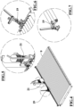
figure 1 illustrates an axonometric view of the machine for separating a load supported by a pallet which is the object of the present invention; -
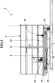
figures 2 and3 illustrate side views of the machine offigure 1 in respective conditions; -
figure 4 illustrates an axonometric view of some interconnected details offigure 1 ; -
figure 5 illustrates an enlarged view of a detail offigure 4 ; -
figures 6 and 7 illustrate an enlarged view of a further detail offigure 4 in respective operating conditions; -
figures 8-13 illustrate schematic views of the machine infigure 1 associated with a load consisting of several layers of packages and one or two pallets in a first possible operating sequence in which the movement of some layers of packages occurs by gravity; -
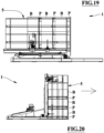
figures 14-20 illustrate schematic views of the machine infigure 1 associated with a load consisting of several layers of packages and with one or two pallets in a second possible operating sequence in which the movement of some layers of packages are operated by motorized means. - With reference to
figures 1-7 ,numeral 1 indicates the machine for separating a load C consisting of several superimposed layers of packages B and supported by a pallet P, object of the present invention. - The basic embodiment of the
machine 1 comprises at least: - a
base element 3 assigned to be placed on, or fixed to, a floor, a surface or a wall; - a
base member 7 defining a respective plane assigned to meet with the face of the pallet P opposite to the load C; - a
slide wall member 9 provided with a set of rolling elements 10, comprising at least one between rollers, wheels, discs, belts and the like, with respective rotation axes perpendicular to the sliding direction and parallel to thepivot pin 14; the rolling elements 10 define a respective tangent geometric plane assigned to match in a slidable way with a lateral face of the load C of the pallet P; where such sliding direction and plane are perpendicular to thebase member 7; - a
pivot pin 14 perpendicular to said sliding direction, parallel to thebase member 7 andslide wall member 9 and placed between them 7, 9 and thebase element 3 for the rotation of saidbase member 7 andslide wall member 9; - a
tilt actuator 15 interconnected between thebase element 3 and saidbase member 7 andslide wall member 9; - a
rotation member 21 associated with theslide wall 9 and provided with at least one motor or at least one gearmotor for the motorized rotation of at least one subset of the rolling elements. - The
tilt actuator 15 is assigned to rotate and tilt thebase member 7 together with theslide wall member 9 around thepivot pin 14 between a first extreme condition in which thebase member 7 and theslide wall member 9 are respectively horizontal and vertical and a second extreme condition in which such elements are rotated by an angle equal to approximately 90° or greater, and in particular theslide wall member 9 is horizontal or inclined downwards in the opposite direction to thepivot pin 14. It is also provided that the rotation can be slightly less than 90° to prevent the load from moving away, due to gravity, from thebase member 7. - The
rotation member 21 is assigned to move part of the load away from thebase member 7 and from the pallet respectively to create a space between the predetermined load layers to insert a load subdivision pallet. - It is optionally provided that the
rotation member 21 can move the entire load, away from thebase member 7 and from the pallet, possibly to remove the original pallet and possibly to replace it with another; thebase member 7 can be eventually provided with optional hooks or clamps to block and to release the pallet. -
Such machine 1, in its preferred embodiment, in addition to thebase element 3, thebase member 7, theslide wall 9, the set of rolling elements 10, thepivot pin 14, thetilt actuator 15 and therotation member 21, comprises: - a
side wall member 11, for example of an almost flat rectangular shape or made up of coplanar longitudinal elements, having dimensions equal to, or greater than, the maximum dimensions of a face, such as the smaller one, of the assembly consisting of each pallet P with the respective load C and suchside wall member 11 is assigned to meet with, or to be adjacent to, such lateral face of the load C of the pallet P; - a compacting
plane member 13 slidably operated along theside wall member 11 towards and away from thebase member 7 to which it is parallel; - a
housing element 5 connected to thebase element 3 and delimited by the latter 3, by theslide wall 9, by theside wall member 11 and by the compactingplane member 13 wheresuch housing element 5 assigned to house the pallet P with the load C to be divided. - The
base element 3, for example, can be of the frame or truss type made of steel beams and of a predominantly two-dimensional shape and it 3 is provided with attachments or fixings for blocking such base element to a horizontal or almost horizontal floor or plane or to a wall. Thebase element 3 is also provided with or connected to seats or supports for thepivot pin 14. - The
base member 7, for example, can comprise a rectangular platform having dimensions equal to or slightly greater than the maximum dimensions of the footprint of the pallets P whose possible use and it 7 is assigned to meet with the face of the pallet P opposite to the load C. - The
slide wall member 9, for example, can be of an almost flat rectangular shape having dimensions equal to or greater than the maximum dimensions of a face, such as the largest one, of the assembly consisting of each pallet P with the respective load C of which it is possible the use. - This
slide wall member 9 is assigned to abut with a lateral face of the load C of the pallet P where this abutment is slidable or movable to allow the translation of at least a portion of the load C. - Preferably the rolling elements 10 are made up of rollers which, as seen previously, are parallel to the
pivot pin 14 and tangential to the defined plane. As clarified below, adjacent subsets or groups, for example of one or more rollers 10, preferably of three rollers 10, are selectively driven by therotation member 21 or each of them 10 is driven, individually or in groups, by respective motors of therotation member 21. - The
base member 7, theslide wall member 9 and theside wall member 11 define respective mutually perpendicular geometric planes and are preferably mutually fixed to a frame or structure which also carries seats or housings for thepivot pin 14. - An edge of the
housing element 5 adjacent to corresponding sides of thebase member 7 and of theslide wall member 9 is connected to thebase member 3 by means of thepivot pin 14 parallel tosuch base 7 andslide wall 9 members. - The
tilt actuator 15, for example consisting of a linear actuator of the electric type or of the hydraulic type with respective pump, or of another type, can have the ends fixed respectively to thebase element 3 and to the frame or to the fixing structure of thebase 7,slide wall 9,side wall 11 members or to one of these three latter 7, 9, 11. - In this way the operation of the
tilt actuator 15 causes the rotation of theentire housing element 5 around thepivot pin 14 between the first extreme condition in which at least theslide wall member 9 and thebase member 7 are respectively vertical and horizontal and the second extreme condition in which thehousing element 5 is rotated by an angle between approximately 80° and 90°, preferably by approximately 90°, or by an angle greater than 90°, compared to the first extreme condition. In this more complete embodiment, the stopping of the sliding of the load, and its compaction with the load subdivision pallet, can be carried out by the compactingplane member 13 and therefore a specific rotation condition of thehousing element 5 at an angle slightly less than 90° is not necessary because the compactingplane member 13 stops the load. - In these second extreme conditions of rotation at 90° or rotation greater than 90°, the
slide wall member 9 is respectively horizontal or inclined downwards in the direction opposite to thepivot pin 14. - In order to operate the rotation of any subset of the rolling means 10, consisting of rollers or the like, the
rotation member 21 is movable and lockable along one side of theslide wall member 9. For this purpose, themachine 1 is provided with at least onerail member 25 and at least onerack member 27 parallel and adjacent to or fixed to a side perpendicular to thepivot pin 14 of theslide wall member 9 and therotation member 21 is slidably movable along therail member 25 and it 21 is provided with a respective blocking lever that can be operated to disengage and engage, with its own tooth, one of the recesses of therack member 27 to release and block the sliding of therotation member 21 itself by engaging it with a corresponding subset of rolling elements 10. - Alternatively, the positioning of the
rotation member 21 along theslide wall 9 can be achieved by means of guide and/or motorized rack and pinion and/or motorized male and female screw actuators or by means of other linear actuators. - The position of the
rotation member 21 along the side of theslide wall member 9 determines which rollers are connected to therotation member 21 itself. - The
rotation member 21 is provided with a motor or gearmotor 16 having a drive pinion 18 for an annular belt or chain 20 engaged on respective free tensioning pinions 22 and on rotation pinions 24 of two or more adjacent rollers 10 of theslide wall 9. - In this case the rollers 10, when not engaged by the
rotation member 21 or by apossible stop member 19 which will be described below, are idle. - Obviously, the transmission of the rotary motion of the
rotation member 21 to the subset of rolling elements can be achieved by means of other transmissions. - Alternatively, the rolling elements 10 of the
slide wall 9 may consist of rollers each of which, or each subset of which, is provided with a motor or gearmotor of therotation member 21 to drive its rotation where such motors or gearmotors can be operated individually or in groups. - The possibility of rotating the
housing element 5, and in particular theslide wall 9, by an angle greater than 90° (as illustrated infigures 8-13 ) provides, for instance, an aid to the translation of the load part to be separated which helps the rotation member in some cases, for example when the surface of the load packages is smooth or slippery and the operable rolling means 10 of therotation member 21 can slip on them. - The
machine 1 may further comprise at least oneoptional stop member 19 which can block and release a corresponding subset of rolling elements 10. - The
stop member 19 is fixed to a side of theslide wall member 9 or it 19 can be moved and locked along theslide wall member 9. - In the first case, the
stop member 19 is fixed to a frame of theslide wall member 9; in the second case thestop member 19 slides along saidrail member 25 and/or to saidrack member 27 or along a respective rail member and/or a respective rack member.
thestop member 19 is provided with an operating lever acting on a blocking element thereof. If thestop member 19 is fixed, the operating lever acting and the respective blocking element are assigned to release and to block at least one rolling element 10 at a time. If thestop member 19 is sliding along theslide wall member 9 frame, the operating lever and the respective blocking element are assigned to release and to block at the same time one or more rolling elements 10 and the sliding of thestop member 19 itself. - As illustrated in the schematic
figures 14-20 which represent a possible operating sequence of the machine also comprising theoptional stop member 19, therotation member 21 allows to separate the layers of packages B to be separated from those blocked by thestop member 19 even when thehousing element 5 in the second extreme condition is inclined by an angle between 80° and 90° or approximately 90°. This allows, for example, to separate layers of packages containing products that cannot be inclined beyond 80° or 90°. - Alternatively, and as seen, the roller conveyor can be of the type with totally idle or motorized rollers that can be operated individually or in groups. It is provided as a further alternative that possible electrically lockable and rotatable rollers can replace both the
stop member 19 and therotation member 21 as above described. - For an easy positioning of the
stop member 19 and/or of therotation member 21, a side perpendicular to thepivot pin 14 of theslide wall member 9 is provided with therail member 25 of the balls circulation type which extends along such side perpendicular to the rotation axes of the rollers and of thepivot pin 14 and parallel to theside wall member 11. Thestop member 19 is provided with its own carriage slidingly movable along therail member 25 and is furthermore provided with said operating lever for its blocking elements assigned to release and block at least one roller at a time, blocking the roller itself and the sliding of thestop member 19 itself were such blocking element can act directly on the ends of the rollers or on their pinions, (if they are provided with them) and is complementary shaped in respect to said ends or pinions. - The
rotation member 21 is provided with a respective carriage slidably movable along therail member 25 and its respective blocking lever is provided with one or more tooth shaped complementarily to the recesses of therack member 27 to release and block the sliding of therotation member 21 itself, positioning it where necessary and allowing it to impart the necessary force, or torque, to the rollers engaged to it without excessive clearance. - The side of the
slide wall member 9 provided with therail 25 and rack 27 members is also provided with arotatable covering member 31, around hinge pins parallel to therail member 25, between a working condition, in which does not interfere with thestop 19,rotation 21 andrail 25 members, and a rest condition in which it partially covers therail member 25 and locks thestop member 19 androtation member 21 in a position opposite thepivot pin 14 preventing them from sliding at least in the first extreme condition. The covering element will be placed in the non-interference condition before positioning thestop 19 androtation 21 members. - The
side wall member 11 is provided with at least one guide, preferably two, perpendicular to the geometric plane of thebase member 7 and parallel to the geometric plane of theslide wall member 9 for the translation of one or more support brackets of the compactingplane member 13. Theside wall member 11 is furthermore provided with a linear actuator, for example of a linear type with a hydraulic cylinder operated by a respective electric pump or, by means of a hydraulic control unit, by the same pump of thetilt actuator 15, with direction of action parallel to the at least one guide and connected to one or more support brackets for the translation of the compactingplane member 13. - The
machine 1 can comprise at least position sensors of the compactingplane members 13, of thestop 19 androtation 21 members, sensors of the status of the coveringelement 31, of the possible hydraulic control unit, of the levers of thestop 19 androtation 21 members and it 1 can further comprise at least one rotation angle detector of thehousing element 5, height and/or dimensions detectors of the load with and/or without a pallet. Such sensors and detectors can be used to provide data on the status of the machine to an operator. - The
machine 1 can furthermore comprise a control means of the programmable digital type connected to the sensors and detectors and assigned to operate or enable the manual operation of the motors, gearmotors and actuators of themachine 1. - It is noted that the separation of layers of the load can be utilized not only for the insertion of pallets but also for other purposes such as, for example, to insert sheets or other elements for stabilizing and strengthening the load, to insert separators or other additional packages.
Claims (14)
- Machine for separating a load (C) made up of several superimposed layers of packages (B) and supported by a pallet (P); said machine (1) comprises at least:- a base element (3) assigned to be placed on, or fixed to, a floor, surface or wall;- a base member (7) defining a respective plane assigned to meet with the face of the pallet (P) opposite to the load (C);- a slide wall member (9) provided with a set of rolling elements (10) with respective rotation axes perpendicular to a sliding direction and defining a respective plane assigned to match in a slidable way with a lateral face of the load (C); where such sliding direction and plane are perpendicular to the base member (7);- a pivot pin (14) perpendicular to said sliding direction, parallel to the base member (7) and to the slide wall member (9) and placed between them (7, 9) and the base element (3) for the rotation of said base member (7) and slide wall member (9);- a tilt actuator (15) interconnected between the base element (3) and said base member (7) and slide wall member (9) to rotate the latter (7, 9) around the pivot pin (14);said machine (1) is characterized in that the slide wall member (9) comprises at least one rotation member (21) provided with at least one motor or at least one gearmotor for the motorized rotation of at least a subset of the rolling elements.
- Machine according to claim 1 characterized in that the rotation member (21) is movable and lockable along one side of the slide wall member (9) for the rotation of a subset of rolling elements (10).
- Machine according to claim 2 characterized in that the rolling elements (10) of the slide wall (9) consist of rollers and in that the rotation member (21) is provided with a motor or gearmotor (16) having a drive pinion (18) for an annular belt or chain (20) engaged on respective free pinions (22) and on rotation pinions (24) of two or more adjacent rollers (10) of the slide wall (9).
- Machine according to claim 1 characterized in that the rolling elements (10) of the slide wall (9) consist of rollers each of which, or each subset of which, is provided with a motor or gearmotor of the rotation member (21) to operate its rotation, where such motors or gearmotors can be operated individually or in groups.
- Machine according to any one of the preceding claims characterized in that it further comprises a side wall member (11) defining a respective plane perpendicular to the base member (7) and to the slide wall member (9) and fixed laterally to said slide wall member (9).
- Machine according to claim 5 characterized in that it further comprises a compacting plane member (13) defining a respective plane parallel to the base member (7) and slidably operated along the side wall member (11) towards and away from the base member (7).
- Machine according to claim 6 characterized in that the base member (7), the slide wall member (9), the side wall member (11) and the compacting plane member (13) delimit a housing element (5) at least for the pallet (P) and its load (C).
- Machine according to any of claims 1-3 or 5-7 characterized in that the slide wall member (9) is provided with at least one rail member (25) and at least one rack member (27) parallel and adjacent or fixed to a side perpendicular to the pivot pin (14) of the slide wall member (9), where the rotation member (21) is slidably movable along the rail member (25) and it is provided with a respective locking lever having a tooth, said locking lever can be operated to disengage and engage the tooth with one of the recesses of the rack member (27) to release and block the sliding of the rotation member (21) itself and to engage it with a corresponding subset of rolling elements (10).
- Machine according to any of the preceding claims characterized in that it comprises at least one stop member (19) which can block and release a corresponding subset of rolling elements (10), where said stop member (19) is fixed to a side of the slide wall member (9), or said stop member (19) can be moved and locked along the slide wall member (9).
- Machine according to claims 9 or 8 and 9 characterized in that the stop member (19) is provided with an operating lever for a blocking element thereof assigned to release and to block at least one rolling element (10) at a time; the stop member is fixed to the slide wall member (9) or it slides along said rail member (25) and/or along said rack member (27) or along a respective rail member and/or a respective rack member.
- Machine according to claims 8 and 9 characterized in that the side of the slide wall member (9) provided with the rail (25) and rack (27) members is also provided with a covering element (31) rotating between a working condition, in which it does not interfere with the stop (19), rotation (21) and rail (25) members, and a rest condition in which it partially covers the rail member (25) and blocks the stop (19) and rotation (21) members in a position opposite to the pivot pin (14).
- Machine according to claims 5 and 6 characterized in that the side wall member (11) is provided with at least one guide perpendicular to the geometric plane of the base member (7) for the sliding of one or more support brackets of the compacting plane member (13) and is further provided with a linear actuator with direction of action parallel to the at least one guide and connected to one or more support brackets for the translation of the compacting plane member (13).
- Machine according to claims 6, 7, 9 and 11 characterized in that it comprises at least position sensors of the compacting plane member (13), of the stop (19) and rotation (21) members, of the status of the covering element (31) of the levers of the stop (19) and rotation (21) members and in that it comprises at least one rotation angle detector of the housing element (5) and/or detectors of the height of the load.
- Machine according to claim 13 characterized in that it comprises control means of the programmable digital type connected to the sensors and detectors and assigned to operate or enable the manual operation of the motors, gearmotors and actuators of the machine (1).
Applications Claiming Priority (1)
| Application Number | Priority Date | Filing Date | Title |
|---|---|---|---|
| IT102023000000336A IT202300000336A1 (en) | 2023-03-17 | 2023-03-17 | MACHINE FOR DIVIDING A LOAD SUPPORTED BY A PALLET |
Publications (3)
| Publication Number | Publication Date |
|---|---|
| EP4446265A1 true EP4446265A1 (en) | 2024-10-16 |
| EP4446265C0 EP4446265C0 (en) | 2025-09-17 |
| EP4446265B1 EP4446265B1 (en) | 2025-09-17 |
Family
ID=87514098
Family Applications (1)
| Application Number | Title | Priority Date | Filing Date |
|---|---|---|---|
| EP24163050.8A Active EP4446265B1 (en) | 2023-03-17 | 2024-03-12 | Machine for separating a load supported by a pallet |
Country Status (3)
| Country | Link |
|---|---|
| US (1) | US12358738B2 (en) |
| EP (1) | EP4446265B1 (en) |
| IT (1) | IT202300000336A1 (en) |
Family Cites Families (12)
| Publication number | Priority date | Publication date | Assignee | Title |
|---|---|---|---|---|
| US2278140A (en) * | 1939-08-24 | 1942-03-31 | United Eng Foundry Co | Pack handling apparatus |
| NO119357B (en) * | 1966-06-11 | 1970-05-11 | G Ruud | |
| DE2707191A1 (en) * | 1976-03-04 | 1977-09-08 | Stobb Inc | DEVICE AND METHOD FOR HANDLING STRAPS FORMED FROM SHEETS, IN PARTICULAR IN THE GRAPHICAL INDUSTRY |
| SE412891B (en) * | 1979-06-20 | 1980-03-24 | Frigoscandia Ab | DEVICE FOR HANDLING OF LOW STACKED PALLASTATE GOODS |
| US4696614A (en) * | 1983-03-23 | 1987-09-29 | Moen Lenard E | Apparatus for recubing boxes |
| FR2543928B1 (en) * | 1983-04-08 | 1986-01-17 | Martin Sa | METHOD AND DEVICE FOR AUTOMATICALLY FEEDING A PLATE PRODUCTS PROCESSING MACHINE |
| DE69321318D1 (en) * | 1992-05-13 | 1998-11-05 | Kao Corp | METHOD AND DEVICE FOR CORRECTING PACKAGING UNITS AND DEVICE USING THIS FOR STACKING PACKAGING IN AUTOMATIC WAREHOUSES |
| NL1008203C2 (en) * | 1998-02-05 | 1999-08-06 | Demcon Product Dev Engineering | Machine for separating layers of objects from stack of trays on pallet |
| WO2004045993A1 (en) * | 2002-11-15 | 2004-06-03 | Gebhardt Transport- Und Lagersysteme Gmbh | Method and device for exchanging transport elements |
| US9150394B2 (en) * | 2008-06-04 | 2015-10-06 | Laitram, L.L.C. | Apparatus and methods for helping unload a pallet |
| DK201670377A1 (en) * | 2016-05-30 | 2017-12-11 | Schur Packaging Systems Ab | Pile Preparation Unit with Pile Turner |
| KR102189542B1 (en) * | 2016-07-22 | 2020-12-11 | 한국전자통신연구원 | Auto loading tipper, apparatus and method for controlling of auto loading tipper |
-
2023
- 2023-03-17 IT IT102023000000336A patent/IT202300000336A1/en unknown
-
2024
- 2024-03-12 EP EP24163050.8A patent/EP4446265B1/en active Active
- 2024-03-16 US US18/607,441 patent/US12358738B2/en active Active
Non-Patent Citations (2)
| Title |
|---|
| AIRFLOW SPACERS LTD: "AIRFLOW SR2.wmv", 10 June 2013 (2013-06-10), XP093092737, Retrieved from the Internet <URL:https://www.youtube.com/watch?v=-pvmrMAQy_A> [retrieved on 20231018] * |
| TOPPY PALLET CHANGER: "Pallet changer "L-Shape Tilter 95�" (insert & remove freezer spacers)", 17 July 2020 (2020-07-17), XP093092744, Retrieved from the Internet <URL:https://www.youtube.com/watch?app=desktop&v=fE9hSdVknAE> [retrieved on 20231018] * |
Also Published As
| Publication number | Publication date |
|---|---|
| EP4446265C0 (en) | 2025-09-17 |
| US20240308789A1 (en) | 2024-09-19 |
| EP4446265B1 (en) | 2025-09-17 |
| US12358738B2 (en) | 2025-07-15 |
| IT202300000336A1 (en) | 2024-09-17 |
Similar Documents
| Publication | Publication Date | Title |
|---|---|---|
| EP0726867B1 (en) | High speed storage system | |
| US20210101535A1 (en) | Rail system for vehicle shelving and canopies | |
| US10518916B2 (en) | Material processing system | |
| CA3177997A1 (en) | Container handling vehicle which can load and/or unload itself | |
| WO2017144055A1 (en) | Telescopic drive, stacker crane comprising same and operating method and use therefor | |
| EP3810529B1 (en) | Automated system and method for the storage and movement of heavy material | |
| CA2880976C (en) | Moving floor system | |
| DK180533B1 (en) | Pallestabler | |
| KR101569468B1 (en) | Automatic stacking apparatus for pallet | |
| EP1932779A1 (en) | Tray transfer mechanism and article storing apparatus using same | |
| CN102341872A (en) | Method and device for stacking | |
| EP0807482B1 (en) | Combination tool changer and storage device for die cutter | |
| KR102275918B1 (en) | Apparatus for removing lump ore for belt conveyor | |
| US20220073291A1 (en) | Device for replacing pallet supporting a load | |
| EP4446265B1 (en) | Machine for separating a load supported by a pallet | |
| US11427415B2 (en) | Automatic loading and unloading device | |
| CN109775392B (en) | Loading system and loading method | |
| US6886386B1 (en) | Press brake punch transfer carriage | |
| EP1119509A1 (en) | Device for transporting goods from one conveyor device to at least one other conveyor device | |
| US20240262639A1 (en) | Device for replacing a pallet carrying a load with a replacement pallet | |
| EP0721889B1 (en) | Gripper for at least one object carrier | |
| CN119100101A (en) | A disc encoder | |
| EP1342867B1 (en) | Automated parking system with movable plattforms for supporting and transporting motor vehicles on previously selected parking positions | |
| CN109677835A (en) | A kind of transplanting mechanism and lifting transplanter | |
| CN215319259U (en) | Plank hot pressing system |
Legal Events
| Date | Code | Title | Description |
|---|---|---|---|
| PUAI | Public reference made under article 153(3) epc to a published international application that has entered the european phase |
Free format text: ORIGINAL CODE: 0009012 |
|
| STAA | Information on the status of an ep patent application or granted ep patent |
Free format text: STATUS: THE APPLICATION HAS BEEN PUBLISHED |
|
| AK | Designated contracting states |
Kind code of ref document: A1 Designated state(s): AL AT BE BG CH CY CZ DE DK EE ES FI FR GB GR HR HU IE IS IT LI LT LU LV MC ME MK MT NL NO PL PT RO RS SE SI SK SM TR |
|
| STAA | Information on the status of an ep patent application or granted ep patent |
Free format text: STATUS: REQUEST FOR EXAMINATION WAS MADE |
|
| 17P | Request for examination filed |
Effective date: 20250228 |
|
| REG | Reference to a national code |
Ref country code: DE Ref legal event code: R079 Free format text: PREVIOUS MAIN CLASS: B65G0060000000 Ipc: B65G0059080000 Ref document number: 602024000674 Country of ref document: DE |
|
| GRAP | Despatch of communication of intention to grant a patent |
Free format text: ORIGINAL CODE: EPIDOSNIGR1 |
|
| STAA | Information on the status of an ep patent application or granted ep patent |
Free format text: STATUS: GRANT OF PATENT IS INTENDED |
|
| RIC1 | Information provided on ipc code assigned before grant |
Ipc: B65G 65/23 20060101ALI20250510BHEP Ipc: B65G 7/08 20060101ALI20250510BHEP Ipc: B65G 59/08 20060101AFI20250510BHEP |
|
| INTG | Intention to grant announced |
Effective date: 20250530 |
|
| RIN1 | Information on inventor provided before grant (corrected) |
Inventor name: PIANI, DANIELE |
|
| GRAS | Grant fee paid |
Free format text: ORIGINAL CODE: EPIDOSNIGR3 |
|
| GRAA | (expected) grant |
Free format text: ORIGINAL CODE: 0009210 |
|
| STAA | Information on the status of an ep patent application or granted ep patent |
Free format text: STATUS: THE PATENT HAS BEEN GRANTED |
|
| AK | Designated contracting states |
Kind code of ref document: B1 Designated state(s): AL AT BE BG CH CY CZ DE DK EE ES FI FR GB GR HR HU IE IS IT LI LT LU LV MC ME MK MT NL NO PL PT RO RS SE SI SK SM TR |
|
| REG | Reference to a national code |
Ref country code: GB Ref legal event code: FG4D |
|
| REG | Reference to a national code |
Ref country code: CH Ref legal event code: EP |
|
| REG | Reference to a national code |
Ref country code: IE Ref legal event code: FG4D |
|
| REG | Reference to a national code |
Ref country code: DE Ref legal event code: R096 Ref document number: 602024000674 Country of ref document: DE |
|
| U01 | Request for unitary effect filed |
Effective date: 20251014 |
|
| U07 | Unitary effect registered |
Designated state(s): AT BE BG DE DK EE FI FR IT LT LU LV MT NL PT RO SE SI Effective date: 20251020 |
|
| PG25 | Lapsed in a contracting state [announced via postgrant information from national office to epo] |
Ref country code: NO Free format text: LAPSE BECAUSE OF FAILURE TO SUBMIT A TRANSLATION OF THE DESCRIPTION OR TO PAY THE FEE WITHIN THE PRESCRIBED TIME-LIMIT Effective date: 20251217 |
|
| PG25 | Lapsed in a contracting state [announced via postgrant information from national office to epo] |
Ref country code: HR Free format text: LAPSE BECAUSE OF FAILURE TO SUBMIT A TRANSLATION OF THE DESCRIPTION OR TO PAY THE FEE WITHIN THE PRESCRIBED TIME-LIMIT Effective date: 20250917 |
|
| PG25 | Lapsed in a contracting state [announced via postgrant information from national office to epo] |
Ref country code: GR Free format text: LAPSE BECAUSE OF FAILURE TO SUBMIT A TRANSLATION OF THE DESCRIPTION OR TO PAY THE FEE WITHIN THE PRESCRIBED TIME-LIMIT Effective date: 20251218 |
|
| PG25 | Lapsed in a contracting state [announced via postgrant information from national office to epo] |
Ref country code: RS Free format text: LAPSE BECAUSE OF FAILURE TO SUBMIT A TRANSLATION OF THE DESCRIPTION OR TO PAY THE FEE WITHIN THE PRESCRIBED TIME-LIMIT Effective date: 20251217 |
|
| PG25 | Lapsed in a contracting state [announced via postgrant information from national office to epo] |
Ref country code: SM Free format text: LAPSE BECAUSE OF FAILURE TO SUBMIT A TRANSLATION OF THE DESCRIPTION OR TO PAY THE FEE WITHIN THE PRESCRIBED TIME-LIMIT Effective date: 20250917 |
|
| PG25 | Lapsed in a contracting state [announced via postgrant information from national office to epo] |
Ref country code: ES Free format text: LAPSE BECAUSE OF FAILURE TO SUBMIT A TRANSLATION OF THE DESCRIPTION OR TO PAY THE FEE WITHIN THE PRESCRIBED TIME-LIMIT Effective date: 20250917 |
|
| PG25 | Lapsed in a contracting state [announced via postgrant information from national office to epo] |
Ref country code: IS Free format text: LAPSE BECAUSE OF FAILURE TO SUBMIT A TRANSLATION OF THE DESCRIPTION OR TO PAY THE FEE WITHIN THE PRESCRIBED TIME-LIMIT Effective date: 20260117 |
|
| PG25 | Lapsed in a contracting state [announced via postgrant information from national office to epo] |
Ref country code: CZ Free format text: LAPSE BECAUSE OF FAILURE TO SUBMIT A TRANSLATION OF THE DESCRIPTION OR TO PAY THE FEE WITHIN THE PRESCRIBED TIME-LIMIT Effective date: 20250917 |
|
| PG25 | Lapsed in a contracting state [announced via postgrant information from national office to epo] |
Ref country code: PL Free format text: LAPSE BECAUSE OF FAILURE TO SUBMIT A TRANSLATION OF THE DESCRIPTION OR TO PAY THE FEE WITHIN THE PRESCRIBED TIME-LIMIT Effective date: 20250917 |
|
| PG25 | Lapsed in a contracting state [announced via postgrant information from national office to epo] |
Ref country code: SK Free format text: LAPSE BECAUSE OF FAILURE TO SUBMIT A TRANSLATION OF THE DESCRIPTION OR TO PAY THE FEE WITHIN THE PRESCRIBED TIME-LIMIT Effective date: 20250917 |
|
| U20 | Renewal fee for the european patent with unitary effect paid |
Year of fee payment: 3 Effective date: 20260331 |