EP4446258A1 - Elastisches transportband, transportsystem mit dem transportband, verfahren zur herstellung des transportbandes - Google Patents
Elastisches transportband, transportsystem mit dem transportband, verfahren zur herstellung des transportbandes Download PDFInfo
- Publication number
- EP4446258A1 EP4446258A1 EP24169368.8A EP24169368A EP4446258A1 EP 4446258 A1 EP4446258 A1 EP 4446258A1 EP 24169368 A EP24169368 A EP 24169368A EP 4446258 A1 EP4446258 A1 EP 4446258A1
- Authority
- EP
- European Patent Office
- Prior art keywords
- conveyor belt
- guide
- transport direction
- width
- groove
- Prior art date
- Legal status (The legal status is an assumption and is not a legal conclusion. Google has not performed a legal analysis and makes no representation as to the accuracy of the status listed.)
- Granted
Links
Images
Classifications
-
- B—PERFORMING OPERATIONS; TRANSPORTING
- B65—CONVEYING; PACKING; STORING; HANDLING THIN OR FILAMENTARY MATERIAL
- B65G—TRANSPORT OR STORAGE DEVICES, e.g. CONVEYORS FOR LOADING OR TIPPING, SHOP CONVEYOR SYSTEMS OR PNEUMATIC TUBE CONVEYORS
- B65G15/00—Conveyors having endless load-conveying surfaces, i.e. belts and like continuous members, to which tractive effort is transmitted by means other than endless driving elements of similar configuration
- B65G15/60—Arrangements for supporting or guiding belts, e.g. by fluid jets
- B65G15/64—Arrangements for supporting or guiding belts, e.g. by fluid jets for automatically maintaining the position of the belts
-
- B—PERFORMING OPERATIONS; TRANSPORTING
- B65—CONVEYING; PACKING; STORING; HANDLING THIN OR FILAMENTARY MATERIAL
- B65G—TRANSPORT OR STORAGE DEVICES, e.g. CONVEYORS FOR LOADING OR TIPPING, SHOP CONVEYOR SYSTEMS OR PNEUMATIC TUBE CONVEYORS
- B65G15/00—Conveyors having endless load-conveying surfaces, i.e. belts and like continuous members, to which tractive effort is transmitted by means other than endless driving elements of similar configuration
- B65G15/30—Belts or like endless load-carriers
- B65G15/32—Belts or like endless load-carriers made of rubber or plastics
-
- B—PERFORMING OPERATIONS; TRANSPORTING
- B65—CONVEYING; PACKING; STORING; HANDLING THIN OR FILAMENTARY MATERIAL
- B65G—TRANSPORT OR STORAGE DEVICES, e.g. CONVEYORS FOR LOADING OR TIPPING, SHOP CONVEYOR SYSTEMS OR PNEUMATIC TUBE CONVEYORS
- B65G15/00—Conveyors having endless load-conveying surfaces, i.e. belts and like continuous members, to which tractive effort is transmitted by means other than endless driving elements of similar configuration
- B65G15/30—Belts or like endless load-carriers
- B65G15/32—Belts or like endless load-carriers made of rubber or plastics
- B65G15/42—Belts or like endless load-carriers made of rubber or plastics having ribs, ridges, or other surface projections
-
- B—PERFORMING OPERATIONS; TRANSPORTING
- B65—CONVEYING; PACKING; STORING; HANDLING THIN OR FILAMENTARY MATERIAL
- B65G—TRANSPORT OR STORAGE DEVICES, e.g. CONVEYORS FOR LOADING OR TIPPING, SHOP CONVEYOR SYSTEMS OR PNEUMATIC TUBE CONVEYORS
- B65G15/00—Conveyors having endless load-conveying surfaces, i.e. belts and like continuous members, to which tractive effort is transmitted by means other than endless driving elements of similar configuration
- B65G15/60—Arrangements for supporting or guiding belts, e.g. by fluid jets
- B65G15/62—Guides for sliding belts
Definitions
- the invention relates to an elastic conveyor belt for transporting goods on the conveyor belt in a transport direction in a transport system.
- the conveyor belt has a guide surface, wherein at least two guide grooves running along the transport direction are introduced into the guide surface for guiding the conveyor belt along the transport direction, wherein the guide grooves are arranged transversely to the transport direction with a groove center distance from one another.
- the transport system comprises at least two guide elements which are designed to engage in the guide grooves for guiding the conveyor belt along the transport direction, wherein the guide elements are arranged transversely to the transport direction with an element center distance from one another.
- the invention further relates to a transport system with the conveyor belt and a manufacturing method for the conveyor belt.
- the object of the invention is to create an elastic conveyor belt as well as a transport system therewith and a manufacturing method therefor, which enable a precise, reliable and low-friction guidance of the conveyor belt.
- the present invention provides an elastic conveyor belt according to claim 1, which solves the technical problem.
- the problem is also solved by a transport system according to claim 10 and a method for producing the conveyor belt according to claim 11.
- Advantageous embodiments are the subject of the dependent claims.
- the elastic conveyor belt according to the invention is designed for transporting goods on the conveyor belt in a transport direction in a transport system.
- the conveyor belt preferably has a supporting surface for carrying the goods.
- the conveyor belt has a guide surface which is opposite the support surface, for example.
- At least two, for example 5 to 20, in particular 10 to 15, guide grooves running along the transport direction are introduced into the guide surface for guiding the conveyor belt along the transport direction.
- the guide grooves are arranged transversely to the transport direction with a groove center distance from each other.
- the groove center distance is the distance between the center lines of adjacent grooves.
- the transport system comprises at least two guide elements which are designed to engage in the guide grooves to guide the conveyor belt along the transport direction.
- the guide elements comprise, for example, guide bolts or guide webs.
- the guide elements are, for example, mounted on a lateral surface of a Guide roller of the transport system around which the conveyor belt is guided.
- the guide elements are arranged transversely to the transport direction with an element center distance from each other.
- the element center distance is the distance between the center lines of adjacent guide elements.
- the groove center distance in an unloaded resting state of the conveyor belt is selected to be one additional center distance larger than the element center distance.
- the conveyor belt is elastic, so that it deforms reversibly in an operating state in which the conveyor belt is used in the transport system to transport goods.
- a belt length of the conveyor belt along the transport direction can, for example, be stretched in the operating state relative to the rest state, for example by 0.5% to 10%, in particular by 1% to 5%, preferably by 2%.
- the stretching of the length of the conveyor belt can lead to a contraction of a belt width of the conveyor belt parallel to the guide surface and transverse to the transport direction in an area of the conveyor belt weakened by the guide grooves.
- the contraction of the belt width in the area of the guide grooves means that the guide grooves are closer together when the conveyor belt is in operation than when the conveyor belt is at rest. If the groove center distance in the rest state corresponded to the element center distance, as is the case with known conveyor belts, the guide elements would not fit precisely into the guide grooves in the operating state due to the contraction of the belt width, resulting in increased friction and increased wear.
- the groove centre distance in the resting state is chosen to be larger than the element centre distance by the additional centre distance, ensures that the guide elements in the operating state, they fit precisely into the guide grooves and thus ensure reliable, precise, low-friction and low-wear guidance.
- the additional center distance is preferably from 0.05% to 5%, preferably from 0.1% to 2.5%, particularly preferably 1% of the element center distance. Such an additional center distance is particularly effective for typical conveyor belts. For an element center distance of 10.0 mm, the additional center distance can be 0.1 mm, for example.
- a belt thickness of the conveyor belt orthogonal to the guide surface is preferably from 0.1 mm to 20 mm, preferably from 1 mm to 10 mm, particularly preferably 2 mm.
- a contraction of the belt width in the area of the guide grooves occurs in particular in conveyor belts with a low belt thickness, such as the belt thickness mentioned. Therefore, the additional center distance is particularly effective in such conveyor belts.
- the guide grooves preferably have a groove depth orthogonal to the guide surface and a groove width parallel to the guide surface and orthogonal to the transport direction, the groove depth and/or the groove width being from 0.25 mm to 5 mm, preferably from 0.5 mm to 2.5 mm, particularly preferably 1 mm.
- a contraction of the strip width in the area of the guide grooves occurs in particular in guide grooves with a large groove depth and/or groove width, such as the groove depth and/or groove width mentioned. The additional center distance is therefore particularly effective in such guide grooves.
- the guide grooves preferably have a groove depth orthogonal to the guide surface and a groove width parallel to the guide surface and orthogonal to the transport direction, wherein the groove depth and/or the groove width is from 25% to 75%, preferably from 40% to 60%, particularly preferably 50%, of a belt thickness of the conveyor belt orthogonal to the guide surface.
- a contraction of the belt width in the area of the guide grooves occurs in particular in guide grooves with relative to the Strip thickness with a large groove depth and/or groove width, such as the groove depth and/or groove width mentioned. Therefore, the additional center distance is particularly effective for such guide grooves.
- the guide grooves preferably have a groove width parallel to the guide surface and orthogonal to the transport direction, wherein the guide elements have an element width parallel to the guide surface and transverse to the transport direction, wherein the groove width in the resting state of the conveyor belt is selected to be larger than the element width by an additional groove width.
- the additional groove width is, for example, a proportion of the additional center distance, wherein the proportion of the additional center distance corresponds, for example, to the proportion of the groove width to the groove center distance.
- the groove width is selected to be larger than the element width by the additional groove width ensures that the guide element fits into the guide groove even if the belt width of the conveyor belt is smaller in the operating state than in the resting state, so that the conveyor belt is guided reliably, precisely, with low friction and low wear.
- the conveyor belt preferably has a web on the guide surface between the guide grooves, the web having a web width parallel to the guide surface and orthogonal to the transport direction.
- the transport system preferably has a gap between the guide elements, the gap having a gap width parallel to the guide surface and transverse to the transport direction.
- the web width when the conveyor belt is at rest is preferably selected to be one additional web width larger than the gap width.
- the web width is selected to be larger than the gap width by the additional web width ensures that the guide elements are arranged to match the guide grooves even if the belt width of the conveyor belt is smaller in the operating state than in the resting state, so that the conveyor belt is guided reliably, precisely, with low friction and low wear.
- the additional web width is, for example, a proportion of the additional center distance, whereby the proportion of the additional center distance corresponds, for example, to the proportion of the web width to the groove center distance.
- the additional web width corresponds, for example, to the additional center distance, so that the web width relative to the gap width is provided with the additional web width, but the groove width relative to the element width has no additional groove width.
- the additional center distance can be adjusted particularly easily, precisely and flexibly because only the distance between the tools used to create the guide grooves in the guide surface, but not the type or shape of the tools, needs to be adjusted in order to adjust the web width and thus the additional center distance.
- the guide grooves preferably have an opening width parallel to the guide surface and orthogonal to the transport direction in a plane with the guide surface and a base width in a plane spaced from the guide surface by a groove depth of the guide groove, the opening width being greater than the base width.
- the guide grooves therefore widen towards the guide elements so that the guide elements automatically center themselves in the guide grooves. This enables reliable, precise, low-friction and low-wear guidance even when a groove width of the guide grooves does not exactly correspond to an element width of the guide elements, for example due to a contraction of the belt width of the conveyor belt.
- This design is therefore particularly advantageously combined with the design in which the additional web width of the web between the guide grooves corresponds to the additional center distance.
- the widening guide grooves have a cross-sectional area orthogonal to the transport direction, which is trough-shaped with a flat bottom and concavely curved flanks or trapezoidal with a flat bottom and flat flanks.
- the base width is preferably zero, with the guide grooves having, for example, a cross-sectional area orthogonal to the transport direction that is V-shaped, U-shaped, parabolic or circular segment-shaped. Guide grooves with a vanishing base width are particularly easy to produce.
- the conveyor belt is, for example, monolithic and preferably consists of a thermoplastic or an elastomer, preferably a polyurethane.
- Elastomers, especially polyurethanes have particularly advantageous properties for a conveyor belt in terms of elasticity, durability, load-bearing capacity and cleanability.
- Polyurethane has particularly advantageous properties for use in the food industry.
- the transport system according to the invention comprises a conveyor belt according to the invention for transporting goods on the conveyor belt in a transport direction.
- the transport system comprises at least two guide elements which are designed to engage in the guide grooves of the conveyor belt in order to guide the conveyor belt along the transport direction, wherein the guide elements are arranged transversely to the transport direction with an element center distance from one another.
- the method according to the invention for producing the elastic conveyor belt according to the invention for transporting goods on the conveyor belt in a transport direction in a transport system according to the invention comprises introducing the guide grooves into the guide surface of the unloaded conveyor belt.
- the guide grooves are introduced into the guide surface with a groove center distance transverse to the transport direction, wherein the groove center distance is selected to be larger by the additional center distance than the element center distance of the guide elements of the transport system.
- the introduction of the guide grooves comprises, for example, machining, in particular milling and/or grinding, of the guide surface of the conveyor belt.
- the conveyor belt is made of polyurethane and has a belt thickness of 2 mm.
- the conveyor belt In the operating state in the associated transport system, the conveyor belt is stretched by 2% along the transport direction relative to the unloaded rest state.
- the guide elements of the transport system have an element center distance of 10.0 mm.
- the additional center distance is 0.1 mm, resulting in a groove center distance of the guide grooves of the conveyor belt in the rest state of 10.1 mm.
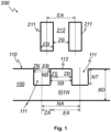
- Figure 1 shows schematically a transport system 200 according to the invention as a cross-section orthogonal to the transport direction TR of the conveyor belt 100 of the transport system 200.
- the conveyor belt 100 has a flat guide surface 110, wherein at least two guide grooves 111 running along the transport direction TR are introduced into the guide surface 110 for guiding the conveyor belt 100 along the transport direction TR.
- the guide grooves 111 are arranged transversely to the transport direction TR with a groove center distance NA from one another.
- the transport system 200 comprises at least two guide elements 211, for example guide webs, which are designed to engage in the guide grooves 111 for guiding the conveyor belt 100 along the transport direction TR.
- the guide elements 211 are arranged transversely to the Transport direction TR with an element center distance EA from each other.
- the groove center distance NA in the shown unloaded resting state of the conveyor belt 100 is selected to be larger than the element center distance EA by an additional center distance ZA.
- the guide grooves 111 have a groove depth NT orthogonal to the guide surface 110 and a groove width NB parallel to the guide surface 110 and orthogonal to the transport direction TR.
- the groove depth NT and/or the groove width NB in the resting state is, for example, from 25% to 75% of a belt thickness BD of the conveyor belt 100 orthogonal to the guide surface 110.
- the guide elements 211 have an element width EB parallel to the guide surface 110 and transverse to the transport direction TR.
- the groove width NB in the resting state is, for example, selected to be larger than the element width EB by an additional groove width ZN.
- the conveyor belt 100 has a web 112 on the guide surface 110 between the guide grooves 111, the web 112 having a web width SB parallel to the guide surface 110 and orthogonal to the transport direction TR.
- the transport system 200 has a gap 212 between the guide elements 211, the gap 212 having a gap width ZB parallel to the guide surface 110 and transverse to the transport direction TR.
- the web width SB in the rest state is selected to be larger than the gap width ZB by an additional web width ZS, for example.
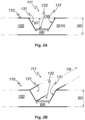
- Figure 2 shows schematically a guide groove 111 in the guide surface 110 of a conveyor belt 100 according to the invention as a cross section orthogonal to the transport direction TR of the conveyor belt 100 ( Fig.2A ) and as a perspective representation ( Fig.2B ).
- the guide groove 111 shown has an opening width OB in a plane parallel to the guide surface 110 and orthogonal to the transport direction TR with the guide surface 110 and a base width BB in a plane spaced from the guide surface 110 by a groove depth NT of the guide groove 111, wherein the opening width OB is greater than the base width BB.
- the guide groove 111 has, for example, a flat base surface 132 parallel to the guide surface 110 and two flat flank surfaces 131 aligned at an angle to the guide surface 110, which connect the base surface 132 to the guide surface 110.
- the guide groove 111 has a trapezoidal cross-sectional area orthogonal to the transport direction TR. If the base width BB were zero with the flank surfaces 131 aligned at an angle to the guide surface 110, the guide groove 111 would have a V-shaped cross-sectional area.
- conveyor belt EB element width 110 guide surface N/A groove center distance 111 guide groove NB groove width 112 web NT groove depth 131 flank surface WHETHER opening width 132 floor area SB bridge width 200 transport system TR transport direction 211 guide element ZA additional center distance 212 space between ZB gap width BB floor width ZN additional groove width BD strip thickness ZS additional web width EA element center distance
Landscapes
- Engineering & Computer Science (AREA)
- Mechanical Engineering (AREA)
- Belt Conveyors (AREA)
- Structure Of Belt Conveyors (AREA)
Abstract
Description
- Die Erfindung betrifft ein elastisches Transportband zum Transport von Gütern auf dem Transportband in eine Transportrichtung in einem Transportsystem. Das Transportband weist eine Führungsfläche auf, wobei in die Führungsfläche mindestens zwei entlang der Transportrichtung verlaufende Führungsnuten zur Führung des Transportbandes entlang der Transportrichtung eingebracht sind, wobei die Führungsnuten quer zur Transportrichtung mit einem Nutmittenabstand voneinander angeordnet sind. Das Transportsystem umfasst mindestens zwei Führungselemente, die dazu eingerichtet sind, zur Führung des Transportbandes entlang der Transportrichtung in die Führungsnuten einzugreifen, wobei die Führungselemente quer zur Transportrichtung mit einem Elementmittenabstand voneinander angeordnet sind.
- Die Erfindung betrifft ferner ein Transportsystem mit dem Transportband und ein Herstellungsverfahren für das Transportband.
- Gattungsgemäße elastische Transportbänder sind beispielsweise aus den Druckschriften
EP 2 679 522 A1 ,EP 3 590 694 A1 undEP 3 623 321 A1 bekannt. Solche Transportbänder werden entlang der Transportrichtung geführt, indem ein oder mehrere Führungselemente in Führungsnuten der Transportbänder eingreifen. Für eine präzise und zuverlässige Führung ist in der Regel eine Vielzahl von Führungselemente und Führungsnuten vorgesehen. Dadurch kommt es jedoch zu einer erhöhten Reibung und einem erhöhten Verschleiß zwischen dem Transportband und den Führungselementen. - Die Aufgabe der Erfindung ist es, ein elastisches Transportband sowie ein Transportsystem damit und ein Herstellungsverfahren dafür zu schaffen, die eine präzise, zuverlässige und reibungsarme Führung des Transportbandes ermöglichen.
- Die vorliegende Erfindung stellt ein elastisches Transportband gemäß Anspruch 1 bereit, das die technische Aufgabe löst. Ebenso wird die Aufgabe durch ein Transportsystem gemäß Anspruch 10 und ein Verfahren zur Herstellung des Transportbandes gemäß Anspruch 11 gelöst. Vorteilhafte Ausgestaltungen sind Gegenstand der abhängigen Ansprüche.
- Das erfindungsgemäße elastische Transportband ist zum Transport von Gütern auf dem Transportband in eine Transportrichtung in einem Transportsystem ausgelegt. Dazu weist das Transportband vorzugsweise eine Tragfläche zum Tragen der Güter auf.
- Das Transportband weist eine Führungsfläche auf, die beispielsweise der Tragfläche gegenüberliegt.
- In die Führungsfläche sind mindestens zwei, beispielsweise 5 bis 20, insbesondere 10 bis 15, entlang der Transportrichtung verlaufende Führungsnuten zur Führung des Transportbandes entlang der Transportrichtung eingebracht.
- Die Führungsnuten sind quer zur Transportrichtung mit einem Nutmittenabstand voneinander angeordnet. Als Nutmittenabstand wird der Abstand der Mittellinien voneinander benachbarter Nuten bezeichnet.
- Das Transportsystem umfasst mindestens zwei Führungselemente, die dazu eingerichtet sind, zur Führung des Transportbandes entlang der Transportrichtung in die Führungsnuten einzugreifen. Die Führungselemente umfassen beispielsweise Führungsbolzen oder Führungsstege. Die Führungselement sind beispielsweise auf einer Mantelfläche einer Führungsrolle des Transportsystems, um die das Transportband geführt ist, angeordnet.
- Die Führungselemente sind quer zur Transportrichtung mit einem Elementmittenabstand voneinander angeordnet. Als Elementmittenabstand wird der Abstand der Mittellinien voneinander benachbarter Führungselemente bezeichnet.
- Der Nutmittenabstand in einem unbelasteten Ruhezustand des Transportbandes ist um einen Zusatzmittenabstand größer gewählt als der Elementmittenabstand.
- Das Transportband ist elastisch, sodass es sich in einem Betriebszustand, in dem das Transportband in dem Transportsystem zum Transport der Güter verwendet wird, reversibel verformt. Eine Bandlänge des Transportbandes entlang der Transportrichtung kann beispielsweise in dem Betriebszustand relativ zu dem Ruhezustand gedehnt sein, beispielsweise um 0,5 % bis 10 %, insbesondere um 1 % bis 5 %, vorzugsweise um 2 %. Durch die Dehnung der Länge des Transportbandes kann es in einem durch die Führungsnuten geschwächten Bereich des Transportbandes zu einer Kontraktion einer Bandbreite des Transportbandes parallel zur Führungsfläche und quer zur Transportrichtung kommen.
- Die Kontraktion der Bandbreite im Bereich der Führungsnuten führt dazu, die Führungsnuten in dem Betriebszustand des Transportbandes näher beieinander liegen als in dem Ruhezustand des Transportbandes. Wenn der Nutmittenabstand in dem Ruhezustand wie bei bekannten Transportbändern dem Elementmittenabstand entspräche, würden die Führungselemente im Betriebszustand aufgrund der Kontraktion der Bandbreite nicht passgenau in die Führungsnuten eingreifen, sodass eine erhöhte Reibung und ein erhöhter Verschleiß entstünden.
- Die Tatsache, dass der Nutmittenabstand im Ruhezustand erfindungsgemäß um den Zusatzmittenabstand größer gewählt ist als der Elementmittenabstand, stellt sicher, dass die Führungselemente im Betriebszustand passgenau in die Führungsnuten eingreifen und somit eine zuverlässige, präzise, reibungsarme und verschleißarme Führung gewährleisten.
- Der Zusatzmittenabstand beträgt vorzugsweise von 0,05 % bis 5 %, bevorzugt von 0,1 % bis 2,5 %, besonders bevorzugt 1 %, des Elementmittenabstands. Ein solcher Zusatzmittenabstand ist für typische Transportbänder besonders wirksam. Bei einem Elementmittenabstand von 10,0 mm kann der Zusatzmittenabstand beispielsweise 0,1 mm betragen.
- Eine Banddicke des Transportbandes orthogonal zur Führungsfläche beträgt vorzugsweise von 0,1 mm bis 20 mm, bevorzugt von 1 mm bis 10 mm, besonders bevorzugt 2 mm. Eine Kontraktion der Bandbreite im Bereich der Führungsnuten tritt insbesondere bei Transportbändern mit geringer Banddicke, wie beispielsweise der genannten Banddicke, auf. Daher ist der Zusatzmittenabstand bei solchen Transportbändern besonders wirksam.
- Die Führungsnuten weisen vorzugsweise eine Nuttiefe orthogonal zur Führungsfläche und eine Nutbreite parallel zur Führungsfläche und orthogonal zur Transportrichtung auf, wobei die Nuttiefe und/oder die Nutbreite von 0,25 mm bis 5 mm, bevorzugt von 0,5 mm bis 2,5 mm, besonders bevorzugt 1 mm, beträgt. Eine Kontraktion der Bandbreite im Bereich der Führungsnuten tritt insbesondere bei Führungsnuten mit großer Nuttiefe und/oder Nutbreite, wie beispielsweise der genannten Nuttiefe und/oder Nutbreite, auf. Daher ist der Zusatzmittenabstand bei solchen Führungsnuten besonders wirksam.
- Die Führungsnuten weisen vorzugsweise eine Nuttiefe orthogonal zur Führungsfläche und eine Nutbreite parallel zur Führungsfläche und orthogonal zur Transportrichtung auf, wobei die Nuttiefe und/oder die Nutbreite von 25 % bis 75 %, bevorzugt von 40 % bis 60 %, besonders bevorzugt 50 %, einer Banddicke des Transportbandes orthogonal zur Führungsfläche beträgt. Eine Kontraktion der Bandbreite im Bereich der Führungsnuten tritt insbesondere bei Führungsnuten mit relativ zur Banddicke großer Nuttiefe und/oder Nutbreite, wie beispielsweise der genannten Nuttiefe und/oder Nutbreite, auf. Daher ist der Zusatzmittenabstand bei solchen Führungsnuten besonders wirksam.
- Die Führungsnuten weisen vorzugsweise eine Nutbreite parallel zur Führungsfläche und orthogonal zur Transportrichtung auf, wobei die Führungselemente eine Elementbreite parallel zur Führungsfläche und quer zur Transportrichtung aufweisen, wobei die Nutbreite im Ruhezustand des Transportbandes um eine Zusatznutbreite größer gewählt ist als die Elementbreite. Dabei beträgt die Zusatznutbreite beispielsweise einen Anteil des Zusatzmittenabstands, wobei der Anteil des Zusatzmittenabstands beispielsweise dem Anteil der Nutbreite an dem Nutmittenabstand entspricht.
- Dadurch, dass die Nutbreite um die Zusatznutbreite größer gewählt ist als die Elementbreite, wird sichergestellt, dass das Führungselement auch dann in die Führungsnut passt, wenn die Bandbreite des Transportbands in dem Betriebszustand geringer als in dem Ruhezustand ist, sodass das Transportband zuverlässig, präzise, reibungsarm und verschleißarm geführt wird.
- Das Transportband weist vorzugsweise an der Führungsfläche zwischen den Führungsnuten einen Steg auf, wobei der Steg eine Stegbreite parallel zur Führungsfläche und orthogonal zur Transportrichtung aufweist. Das Transportsystem weist vorzugsweise zwischen den Führungselementen einen Zwischenraum auf, wobei der Zwischenraum eine Zwischenraum breite parallel zur Führungsfläche und quer zur Transportrichtung aufweist. Die Stegbreite im Ruhezustand des Transportbandes ist vorzugsweise um eine Zusatzstegbreite größer gewählt als die Zwischenraumbreite.
- Dadurch, dass die Stegbreite um die Zusatzstegbreite größer gewählt ist als die Zwischenraum breite, wird sichergestellt, dass die Führungselemente auch dann passend zu den Führungsnuten angeordnet sind, wenn die Bandbreite des Transportbands im Betriebszustand geringer als im Ruhezustand ist, sodass das Transportband zuverlässig, präzise, reibungsarm und verschleißarm geführt wird.
- Die Zusatzstegbreite beträgt beispielsweise einen Anteil des Zusatzmittenabstands, wobei der Anteil des Zusatzmittenabstands beispielsweise dem Anteil der Stegbreite an dem Nutmittenabstand entspricht.
- Die Zusatzstegbreite entspricht beispielsweise dem Zusatzmittenabstand, sodass die Stegbreite relativ zur Zwischenraum breite mit der Zusatzstegbreite versehen ist, aber die Nutbreite relativ zur Elementbreite keine Zusatznutbreite aufweist. In dieser Ausgestaltung lässt sich der Zusatzmittenabstand besonders einfach, präzise und flexibel einstellen, weil nur der Abstand der Werkzeuge, mit denen die Führungsnuten in die Führungsfläche eingebracht werden, zueinander aber nicht die Art oder Form der Werkzeuge eingestellte werden muss, um die Stegbreite und somit den Zusatzmittenabstand einzustellen.
- Die Führungsnuten weisen vorzugsweise parallel zur Führungsfläche und orthogonal zur Transportrichtung eine Öffnungsbreite in einer Ebene mit der Führungsfläche und eine Bodenbreite in einer um eine Nuttiefe der Führungsnut von der Führungsfläche beabstandeten Ebene auf, wobei die Öffnungsbreite größer ist als die Bodenbreite. Die Führungsnuten erweitern sich also auf die Führungselemente zu, sodass sich die Führungselemente selbsttätig in den Führungsnuten zentrieren. Dadurch ist auch dann eine zuverlässige, präzise, reibungsarme und verschleißarme Führung möglich, wenn eine Nutbreite der Führungsnuten, beispielsweise durch eine Kontraktion der Bandbreite des Transportbandes, nicht exakt einer Elementbreite der Führungselemente entspricht. Daher wird diese Ausgestaltung besonders vorteilhaft mit der Ausgestaltung kombiniert, in der die Zusatzstegbreite des Steges zwischen den Führungsnuten dem Zusatzmittenabstand entspricht.
- Die sich erweiternden Führungsnuten haben beispielsweise eine Querschnittsfläche orthogonal zur Transportrichtung, die wannenförmig mit einem planen Boden und konkav gewölbten Flanken oder trapezförmig mit einem planen Boden und planen Flanken ist.
- Die Bodenbreite ist bevorzugt null, wobei die Führungsnuten beispielsweise eine Querschnittsfläche orthogonal zur Transportrichtung haben, die v-förmig, u-förmig, parabelförmig oder kreissegmentförmig ist. Führungsnuten mit verschwindender Bodenbreite sind besonders einfach herstellbar.
- Das Transportband ist beispielsweise monolithisch und besteht vorzugsweise aus einem Thermoplast oder aus einem Elastomer, bevorzugt aus einem Polyurethan. Elastomere, insbesondere Polyurethane, haben bezüglich Elastizität, Haltbarkeit, Tragfähigkeit und Reinigungsfähigkeit besonders vorteilhafte Eigenschaften für ein Transportband. Polyurethan hat besonders vorteilhafte Eigenschaften für den Einsatz in der Lebensmittelindustrie.
- Das erfindungsgemäße Transportsystem umfasst ein erfindungsgemäßes Transportband zum Transport von Gütern auf dem Transportband in einer Transportrichtung.
- Das Transportsystem umfasst mindestens zwei Führungselemente, die dazu eingerichtet sind, zur Führung des Transportbandes entlang der Transportrichtung in die Führungsnuten des Transportbandes einzugreifen, wobei die Führungselemente quer zur Transportrichtung mit einem Elementmittenabstand voneinander angeordnet sind.
- Das erfindungsgemäße Verfahren zur Herstellung des erfindungsgemäßen elastischen Transportbandes zum Transport von Gütern auf dem Transportband in eine Transportrichtung in einem erfindungsgemäßen Transportsystem umfasst ein Einbringen der Führungsnuten in die Führungsfläche des unbelasteten Transportbandes. Die Führungsnuten werden mit einem Nutmittenabstand quer zur Transportrichtung voneinander in die Führungsfläche eingebracht, wobei der Nutmittenabstand um den Zusatzmittenabstand größer gewählt wird als der Elementmittenabstand der Führungselemente des Transportsystems.
- Das Einbringen der Führungsnuten umfasst beispielsweise eine spanende Bearbeitung, insbesondere ein Fräsen und/oder ein Schleifen, der Führungsfläche des Transportbandes.
- In einer beispielhaften Ausgestaltung besteht das Transportband aus Polyurethan und hat eine Banddicke von 2 mm. Das Transportband wird im Betriebszustand in dem zugehörigen Transportsystem relativ zum unbelasteten Ruhezustand entlang der Transportrichtung um 2 % gedehnt. Die Führungselemente des Transportsystems haben einen Elementmittenabstand von 10,0 mm. Der Zusatzmittenabstand beträgt 0,1 mm, sodass sich ein Nutmittenabstand der Führungsnuten des Transportbandes im Ruhezustand von 10,1 mm ergibt.
- Weitere Vorteile, Ziele und Eigenschaften der Erfindung werden anhand nachfolgender Beschreibung und anliegender Zeichnungen erläutert, in welchen beispielhaft erfindungsgemäße Gegenstände dargestellt sind.
-
Figur 1 zeigt schematisch ein erfindungsgemäßes Transportsystem. -
Figur 2 zeigt schematisch eine Führungsnut eines erfindungsgemäßen Transportbandes. -
Figur 1 zeigt schematisch ein erfindungsgemäßes Transportsystem 200 als Querschnitt orthogonal zur Transportrichtung TR des Transportbandes 100 des Transportsystems 200. - Das Transportband weist 100 eine flächige Führungsfläche 110 auf, wobei in die Führungsfläche 110 mindestens zwei entlang der Transportrichtung TR verlaufende Führungsnuten 111 zur Führung des Transportbandes 100 entlang der Transportrichtung TR eingebracht sind. Die Führungsnuten 111 sind quer zur Transportrichtung TR mit einem Nutmittenabstand NA voneinander angeordnet.
- Das Transportsystem 200 umfasst mindestens zwei Führungselemente 211, beispielsweise Führungsstege, die dazu eingerichtet sind, zur Führung des Transportbandes 100 entlang der Transportrichtung TR in die Führungsnuten 111 einzugreifen. Die Führungselemente 211 sind quer zur Transportrichtung TR mit einem Elementmittenabstand EA voneinander angeordnet.
- Der Nutmittenabstand NA in dem gezeigten unbelasteten Ruhezustand des Transportbandes 100 ist um einen Zusatzmittenabstand ZA größer gewählt als der Elementmittenabstand EA.
- Die Führungsnuten 111 weisen eine Nuttiefe NT orthogonal zur Führungsfläche 110 und eine Nutbreite NB parallel zur Führungsfläche 110 und orthogonal zur Transportrichtung TR auf. Die Nuttiefe NT und/oder die Nutbreite NB beträgt im Ruhezustand beispielsweise von 25 % bis 75 % einer Banddicke BD des Transportbandes 100 orthogonal zur Führungsfläche 110.
- Die Führungselemente 211 weisen eine Elementbreite EB parallel zur Führungsfläche 110 und quer zur Transportrichtung TR auf. Die Nutbreite NB im Ruhezustand ist beispielsweise um eine Zusatznutbreite ZN größer gewählt als die Elementbreite EB.
- Das Transportband 100 weist an der Führungsfläche 110 zwischen den Führungsnuten 111 einen Steg 112 auf, wobei der Steg 112 eine Stegbreite SB parallel zur Führungsfläche 110 und orthogonal zur Transportrichtung TR aufweist. Das Transportsystem 200 weist zwischen den Führungselementen 211 einen Zwischenraum 212 auf, wobei der Zwischenraum 212 eine Zwischenraumbreite ZB parallel zur Führungsfläche 110 und quer zur Transportrichtung TR aufweist. Die Stegbreite SB im Ruhezustand ist beispielsweise um eine Zusatzstegbreite ZS größer gewählt als die Zwischenraumbreite ZB.
-
Figur 2 zeigt schematisch eine Führungsnut 111 in der Führungsfläche 110 eines erfindungsgemäßen Transportbandes 100 als Querschnitt orthogonal zur Transportrichtung TR des Transportbandes 100 (Fig.2A ) und als Perspektivdarstellung (Fig.2B ). - Die gezeigte Führungsnut 111 weist parallel zur Führungsfläche 110 und orthogonal zur Transportrichtung TR eine Öffnungsbreite OB in einer Ebene mit der Führungsfläche 110 und eine Bodenbreite BB in einer um eine Nuttiefe NT der Führungsnut 111 von der Führungsfläche 110 beabstandeten Ebene auf, wobei die Öffnungsbreite OB größer ist als die Bodenbreite BB.
- Die Führungsnut 111 hat beispielsweise eine plane und zur Führungsfläche 110 parallele Bodenfläche 132 und zwei plane und schräg zur Führungsfläche 110 ausgerichtete Flankenflächen 131, die die Bodenfläche 132 mit der Führungsfläche 110 verbinden. Dadurch hat die Führungsnut 111 eine trapezförmige Querschnittsfläche orthogonal zur Transportrichtung TR. Wenn die Bodenbreite BB bei planen und schräg zur Führungsfläche 110 ausgerichteten Flankenflächen 131 null wäre, hätte die Führungsnut 111 eine v-förmige Querschnittsfläche.
-
100 Transportband EB Elementbreite 110 Führungsfläche NA Nutmittenabstand 111 Führungsnut NB Nutbreite 112 Steg NT Nuttiefe 131 Flankenfläche OB Öffnungsbreite 132 Bodenfläche SB Stegbreite 200 Transportsystem TR Transportrichtung 211 Führungselement ZA Zusatzmittenabstand 212 Zwischenraum ZB Zwischenraumbreite BB Bodenbreite ZN Zusatznutbreite BD Banddicke ZS Zusatzstegbreite EA Elementmittenabstand
Claims (11)
- Elastisches Transportband (100) zum Transport von Gütern auf dem Transportband (100) in eine Transportrichtung (TR) in einem Transportsystem (200),a. wobei das Transportband (100) eine Führungsfläche (110) aufweist,b. wobei in die Führungsfläche (110) mindestens zwei entlang der Transportrichtung (TR) verlaufende Führungsnuten (111) zur Führung des Transportbandes (100) entlang der Transportrichtung (TR) eingebracht sind,c. wobei die mindestens zwei Führungsnuten (111) quer zur Transportrichtung (TR) mit einem Nutmittenabstand (NA) voneinander angeordnet sind,d. wobei das Transportsystem (200) mindestens zwei Führungselemente (211) umfasst, die dazu eingerichtet sind, zur Führung des Transportbandes (100) entlang der Transportrichtung (TR) in die mindestens zwei Führungsnuten (111) einzugreifen,e. wobei die mindestens zwei Führungselemente (211) quer zur Transportrichtung (TR) mit einem Elementmittenabstand (EA) voneinander angeordnet sind,f. wobei der Nutmittenabstand (NA) in einem unbelasteten Ruhezustand des Transportbandes (100) um einen Zusatzmittenabstand (ZA) größer gewählt ist als der Elementmittenabstand (EA),g. wobei das Transportband (100) an der Führungsfläche (110) zwischen den mindestens zwei Führungsnuten (111) einen Steg (112) aufweist,h. wobei der Steg (112) eine Stegbreite (SB) parallel zur Führungsfläche (110) und orthogonal zur Transportrichtung (TR) aufweist,i. wobei das Transportsystem (200) zwischen den mindestens zwei Führungselementen (211) einen Zwischenraum (212) aufweist,j. wobei der Zwischenraum (212) eine Zwischenraumbreite (ZB) parallel zur Führungsfläche (110) und quer zur Transportrichtung (TR) aufweist, dadurch gekennzeichnet, dassk. die Stegbreite (SB) im Ruhezustand des Transportbandes (100) um eine Zusatzstegbreite (ZS) größer gewählt ist als die Zwischenraum breite (ZB).
- Elastisches Transportband (100) nach Anspruch 1,
wobei der Zusatzmittenabstand (ZA) von 0,05 % bis 5 % des Elementmittenabstands (EA) beträgt. - Elastisches Transportband (100) nach einem der Ansprüche 1 bis 2, wobei eine Banddicke (BD) des Transportbandes (100) orthogonal zur Führungsfläche (110) von 0,1 mm bis 20 mm beträgt.
- Elastisches Transportband (100) nach einem der Ansprüche 1 bis 3,a. wobei die mindestens zwei Führungsnuten (111) eine Nuttiefe (NT) orthogonal zur Führungsfläche (110) und eine Nutbreite (NB) parallel zur Führungsfläche (110) und orthogonal zur Transportrichtung (TR) aufweisen,b. wobei die Nuttiefe (NT) und/oder die Nutbreite (NB) von 0,25 mm bis 5 mm beträgt.
- Elastisches Transportband (100) nach einem der Ansprüche 1 bis 4,a. wobei die mindestens zwei Führungsnuten (111) eine Nuttiefe (NT) orthogonal zur Führungsfläche (110) und eine Nutbreite (NB) parallel zur Führungsfläche (110) und orthogonal zur Transportrichtung (TR) aufweisen,b. wobei die Nuttiefe (NT) und/oder die Nutbreite (NB) im Ruhezustand des Transportbandes (100) von 25 % bis 75 % einer Banddicke (BD) des Transportbandes (100) orthogonal zur Führungsfläche (110) beträgt.
- Elastisches Transportband (100) nach einem der Ansprüche 1 bis 5,a. wobei die mindestens zwei Führungsnuten (111) eine Nutbreite (NB) parallel zur Führungsfläche (110) und orthogonal zur Transportrichtung (TR) aufweisen,b. wobei die mindestens zwei Führungselemente (211) eine Elementbreite (EB) parallel zur Führungsfläche (110) und quer zur Transportrichtung (TR) aufweisen,c. wobei die Nutbreite (NB) im Ruhezustand des Transportbandes (100) um eine Zusatznutbreite (ZN) größer gewählt ist als die Elementbreite (EB).
- Elastisches Transportband (100) nach einem der Ansprüche 1 bis 6, wobei die Zusatzstegbreite (ZS) dem Zusatzmittenabstand (ZA) entspricht.
- Elastisches Transportband (100) nach einem der Ansprüche 1 bis 7,a. wobei die mindestens zwei Führungsnuten (111) parallel zur Führungsfläche (110) und orthogonal zur Transportrichtung (TR) eine Öffnungsbreite (OB) in einer Ebene mit der Führungsfläche (110) und eine Bodenbreite (BB) in einer um eine Nuttiefe (NT) der Führungsnut (111) von der Führungsfläche (110) beabstandeten Ebene aufweist,b. wobei die Öffnungsbreite (OB) größer ist als die Bodenbreite (BB).
- Elastisches Transportband (100) nach einem der Ansprüche 1 bis 8, wobei das Transportband (100) aus einem Thermoplast oder aus einem Elastomer besteht.
- Transportsystem (200)a. umfassend ein Transportband (100) nach einem der Ansprüche 1 bis 9 zum Transport von Gütern auf dem Transportband (100) in einer Transportrichtung (TR),b. wobei das Transportsystem (200) die mindestens zwei Führungselemente (211) umfasst, die dazu eingerichtet sind, zur Führung des Transportbandes (100) entlang der Transportrichtung (TR) in die mindestens zwei Führungsnuten (111) des Transportbandes (100) einzugreifen,c. wobei die mindestens zwei Führungselemente (211) quer zur Transportrichtung (TR) mit dem Elementmittenabstand (EA) voneinander angeordnet sind.
- Verfahren zur Herstellung eines elastischen Transportbandes (100) nach einem der Ansprüche 1 bis 9 zum Transport von Gütern auf dem Transportband (100) in eine Transportrichtung (TR) in einem Transportsystem (200) nach Anspruch 10, das Verfahren umfassend folgende Schritte:a. Einbringen der mindestens zwei Führungsnuten (111) in die Führungsfläche (110) des unbelasteten Transportbandes (100),b. wobei die mindestens zwei Führungsnuten (111) mit einem Nutmittenabstand (NA) quer zur Transportrichtung (TR) voneinander in die Führungsfläche (110) eingebracht werden,c. wobei der Nutmittenabstand (NA) um den Zusatzmittenabstand (ZA) größer gewählt wird als der Elementmittenabstand (EA) der mindestens zwei Führungselemente (211) des Transportsystems (200).
Applications Claiming Priority (1)
| Application Number | Priority Date | Filing Date | Title |
|---|---|---|---|
| DE102023109087.9A DE102023109087A1 (de) | 2023-04-11 | 2023-04-11 | Elastisches Transportband, Transportsystem mit dem Transportband, Verfahren zur Herstellung des Transportbandes |
Publications (3)
| Publication Number | Publication Date |
|---|---|
| EP4446258A1 true EP4446258A1 (de) | 2024-10-16 |
| EP4446258B1 EP4446258B1 (de) | 2026-02-25 |
| EP4446258C0 EP4446258C0 (de) | 2026-02-25 |
Family
ID=92799933
Family Applications (1)
| Application Number | Title | Priority Date | Filing Date |
|---|---|---|---|
| EP24169368.8A Active EP4446258B1 (de) | 2023-04-11 | 2024-04-10 | Transportsystem umfassend ein elastisches transportband |
Country Status (3)
| Country | Link |
|---|---|
| EP (1) | EP4446258B1 (de) |
| DE (1) | DE102023109087A1 (de) |
| ES (1) | ES3066706T3 (de) |
Citations (4)
| Publication number | Priority date | Publication date | Assignee | Title |
|---|---|---|---|---|
| EP2679522A1 (de) | 2012-06-27 | 2014-01-01 | Knopp-Fördertechnik | Transportbandelement zum Transportieren von Gütern, Verfahren zum Führen eines Transportbandelements und Anordnung aus einem Transportbandelement und einer Umlenk- und/oder Antriebswalzenvorrichtung |
| EP3590694A1 (de) | 2018-07-05 | 2020-01-08 | Wallroth F & E UG | Elastisches transportband und herstellungsverfahren |
| EP3623321A1 (de) | 2018-09-13 | 2020-03-18 | Wallroth F & E UG | Transportsystem, verfahren zur herstellung des transportsystems |
| DE102021127421A1 (de) * | 2021-07-05 | 2023-01-05 | Weber Maschinenbau Gmbh Breidenbach | Transporteinrichtung |
Family Cites Families (1)
| Publication number | Priority date | Publication date | Assignee | Title |
|---|---|---|---|---|
| AT396673B (de) * | 1989-11-06 | 1993-11-25 | Andritz Ag Maschf | Verfahren und vorrichtung zur herstellung eines förderbandgurtes |
-
2023
- 2023-04-11 DE DE102023109087.9A patent/DE102023109087A1/de active Pending
-
2024
- 2024-04-10 EP EP24169368.8A patent/EP4446258B1/de active Active
- 2024-04-10 ES ES24169368T patent/ES3066706T3/es active Active
Patent Citations (4)
| Publication number | Priority date | Publication date | Assignee | Title |
|---|---|---|---|---|
| EP2679522A1 (de) | 2012-06-27 | 2014-01-01 | Knopp-Fördertechnik | Transportbandelement zum Transportieren von Gütern, Verfahren zum Führen eines Transportbandelements und Anordnung aus einem Transportbandelement und einer Umlenk- und/oder Antriebswalzenvorrichtung |
| EP3590694A1 (de) | 2018-07-05 | 2020-01-08 | Wallroth F & E UG | Elastisches transportband und herstellungsverfahren |
| EP3623321A1 (de) | 2018-09-13 | 2020-03-18 | Wallroth F & E UG | Transportsystem, verfahren zur herstellung des transportsystems |
| DE102021127421A1 (de) * | 2021-07-05 | 2023-01-05 | Weber Maschinenbau Gmbh Breidenbach | Transporteinrichtung |
Also Published As
| Publication number | Publication date |
|---|---|
| ES3066706T3 (en) | 2026-05-14 |
| EP4446258B1 (de) | 2026-02-25 |
| DE102023109087A1 (de) | 2024-10-17 |
| EP4446258C0 (de) | 2026-02-25 |
Similar Documents
| Publication | Publication Date | Title |
|---|---|---|
| EP2480801B1 (de) | Stahlseilfördergurt mit einem verbindungsscharnier zum koppeln zweier gurtenden | |
| EP3147239B1 (de) | Zahnriemen mit integrierten stützrollen | |
| DE102008058112A1 (de) | Plattenfördervorrichtung | |
| DE60210644T2 (de) | Aufzugsriemen mit geräuschreduzierender nutenanordnung | |
| WO2016177546A1 (de) | Lager zum dämpfen von schwingungen in führungsschienen einer aufzugsanlage | |
| DE112012003767B4 (de) | Bewegungsführungsvorrichtung | |
| DE102018122451A1 (de) | Elastisches Transportband für ein Transportsystem, Antriebswalze zum Antrieb des Transportbandes, Transportsystem, Verfahren zur Herstellung der Antriebswalze | |
| EP3115642B1 (de) | Gurt oder gurtsegment | |
| DE102014224291A1 (de) | Fördergurt | |
| EP4446258B1 (de) | Transportsystem umfassend ein elastisches transportband | |
| DE4214985A1 (de) | Entspannte linearbewegungseinheit | |
| EP3320225A1 (de) | Gurt oder gurtsegment | |
| EP0631359B1 (de) | Kabelmuffe aus Kunststoff, bestehend aus einem geschlitzten Muffenrohr und stirnseitigen Dichtungskörpern | |
| EP0222416A1 (de) | Einspannlagerbuchse | |
| DE69201569T2 (de) | Gurtförderer. | |
| EP3517461B1 (de) | Magnetfördereinrichtung | |
| EP2454111B1 (de) | Halteleiste zum halten und positionieren einer dichtung | |
| EP3390859A1 (de) | Gurt oder gurtsegment | |
| EP4283160B1 (de) | Gurt oder gurtsegment | |
| DE3517391C2 (de) | Riemenscheibe für einen Riementrieb | |
| EP4102100B1 (de) | Verbindung | |
| EP4416409B1 (de) | Linearantrieb | |
| DE102018116347A1 (de) | Elastisches Transportband und Transportsystem | |
| DE102024204806A1 (de) | Riemen mit besonderer Eignung im Tieftemperaturbereich und Verfahren zu dessen Herstellung | |
| DE19820876A1 (de) | Formschlüssige und selbstführende Antriebsanordnung |
Legal Events
| Date | Code | Title | Description |
|---|---|---|---|
| PUAI | Public reference made under article 153(3) epc to a published international application that has entered the european phase |
Free format text: ORIGINAL CODE: 0009012 |
|
| STAA | Information on the status of an ep patent application or granted ep patent |
Free format text: STATUS: REQUEST FOR EXAMINATION WAS MADE |
|
| 17P | Request for examination filed |
Effective date: 20240829 |
|
| AK | Designated contracting states |
Kind code of ref document: A1 Designated state(s): AL AT BE BG CH CY CZ DE DK EE ES FI FR GB GR HR HU IE IS IT LI LT LU LV MC ME MK MT NL NO PL PT RO RS SE SI SK SM TR |
|
| GRAP | Despatch of communication of intention to grant a patent |
Free format text: ORIGINAL CODE: EPIDOSNIGR1 |
|
| STAA | Information on the status of an ep patent application or granted ep patent |
Free format text: STATUS: GRANT OF PATENT IS INTENDED |
|
| INTG | Intention to grant announced |
Effective date: 20251117 |
|
| GRAS | Grant fee paid |
Free format text: ORIGINAL CODE: EPIDOSNIGR3 |
|
| GRAA | (expected) grant |
Free format text: ORIGINAL CODE: 0009210 |
|
| STAA | Information on the status of an ep patent application or granted ep patent |
Free format text: STATUS: THE PATENT HAS BEEN GRANTED |
|
| AK | Designated contracting states |
Kind code of ref document: B1 Designated state(s): AL AT BE BG CH CY CZ DE DK EE ES FI FR GB GR HR HU IE IS IT LI LT LU LV MC ME MK MT NL NO PL PT RO RS SE SI SK SM TR |
|
| REG | Reference to a national code |
Ref country code: CH Ref legal event code: F10 Free format text: ST27 STATUS EVENT CODE: U-0-0-F10-F00 (AS PROVIDED BY THE NATIONAL OFFICE) Effective date: 20260225 Ref country code: GB Ref legal event code: FG4D Free format text: NOT ENGLISH |
|
| REG | Reference to a national code |
Ref country code: DE Ref legal event code: R096 Ref document number: 502024000773 Country of ref document: DE |
|
| REG | Reference to a national code |
Ref country code: CH Ref legal event code: R17 Free format text: ST27 STATUS EVENT CODE: U-0-0-R10-R17 (AS PROVIDED BY THE NATIONAL OFFICE) Effective date: 20260318 |
|
| REG | Reference to a national code |
Ref country code: IE Ref legal event code: FG4D Free format text: LANGUAGE OF EP DOCUMENT: GERMAN |
|
| U01 | Request for unitary effect filed |
Effective date: 20260312 |
|
| U07 | Unitary effect registered |
Designated state(s): AT BE BG DE DK EE FI FR IT LT LU LV MT NL PT RO SE SI Effective date: 20260318 |
|
| REG | Reference to a national code |
Ref country code: ES Ref legal event code: FG2A Ref document number: 3066706 Country of ref document: ES Kind code of ref document: T3 Effective date: 20260514 |
|
| U20 | Renewal fee for the european patent with unitary effect paid |
Year of fee payment: 3 Effective date: 20260416 |
|
| PG25 | Lapsed in a contracting state [announced via postgrant information from national office to epo] |
Ref country code: RS Free format text: LAPSE BECAUSE OF FAILURE TO SUBMIT A TRANSLATION OF THE DESCRIPTION OR TO PAY THE FEE WITHIN THE PRESCRIBED TIME-LIMIT Effective date: 20260525 |
|
| PGFP | Annual fee paid to national office [announced via postgrant information from national office to epo] |
Ref country code: ES Payment date: 20260520 Year of fee payment: 3 |
|
| PG25 | Lapsed in a contracting state [announced via postgrant information from national office to epo] |
Ref country code: PL Free format text: LAPSE BECAUSE OF FAILURE TO SUBMIT A TRANSLATION OF THE DESCRIPTION OR TO PAY THE FEE WITHIN THE PRESCRIBED TIME-LIMIT Effective date: 20260225 |
|
| PG25 | Lapsed in a contracting state [announced via postgrant information from national office to epo] |
Ref country code: GR Free format text: LAPSE BECAUSE OF FAILURE TO SUBMIT A TRANSLATION OF THE DESCRIPTION OR TO PAY THE FEE WITHIN THE PRESCRIBED TIME-LIMIT Effective date: 20260526 |
|
| PG25 | Lapsed in a contracting state [announced via postgrant information from national office to epo] |
Ref country code: NO Free format text: LAPSE BECAUSE OF FAILURE TO SUBMIT A TRANSLATION OF THE DESCRIPTION OR TO PAY THE FEE WITHIN THE PRESCRIBED TIME-LIMIT Effective date: 20260525 |
|
| PG25 | Lapsed in a contracting state [announced via postgrant information from national office to epo] |
Ref country code: HR Free format text: LAPSE BECAUSE OF FAILURE TO SUBMIT A TRANSLATION OF THE DESCRIPTION OR TO PAY THE FEE WITHIN THE PRESCRIBED TIME-LIMIT Effective date: 20260225 |
|
| PG25 | Lapsed in a contracting state [announced via postgrant information from national office to epo] |
Ref country code: IS Free format text: LAPSE BECAUSE OF FAILURE TO SUBMIT A TRANSLATION OF THE DESCRIPTION OR TO PAY THE FEE WITHIN THE PRESCRIBED TIME-LIMIT Effective date: 20260625 |