EP4446232A1 - Verfahren zur steuerung eines mehrmotorigen drehflügelflugzeugs mit reduziertem bodenverbrauch - Google Patents
Verfahren zur steuerung eines mehrmotorigen drehflügelflugzeugs mit reduziertem bodenverbrauch Download PDFInfo
- Publication number
- EP4446232A1 EP4446232A1 EP24153732.3A EP24153732A EP4446232A1 EP 4446232 A1 EP4446232 A1 EP 4446232A1 EP 24153732 A EP24153732 A EP 24153732A EP 4446232 A1 EP4446232 A1 EP 4446232A1
- Authority
- EP
- European Patent Office
- Prior art keywords
- engine
- phase
- period
- active
- power
- Prior art date
- Legal status (The legal status is an assumption and is not a legal conclusion. Google has not performed a legal analysis and makes no representation as to the accuracy of the status listed.)
- Granted
Links
Images


Classifications
-
- B—PERFORMING OPERATIONS; TRANSPORTING
- B64—AIRCRAFT; AVIATION; COSMONAUTICS
- B64D—EQUIPMENT FOR FITTING IN OR TO AIRCRAFT; FLIGHT SUITS; PARACHUTES; ARRANGEMENT OR MOUNTING OF POWER PLANTS OR PROPULSION TRANSMISSIONS IN AIRCRAFT
- B64D31/00—Power plant control systems; Arrangement of power plant control systems in aircraft
- B64D31/02—Initiating means
- B64D31/04—Initiating means actuated personally
-
- B—PERFORMING OPERATIONS; TRANSPORTING
- B64—AIRCRAFT; AVIATION; COSMONAUTICS
- B64D—EQUIPMENT FOR FITTING IN OR TO AIRCRAFT; FLIGHT SUITS; PARACHUTES; ARRANGEMENT OR MOUNTING OF POWER PLANTS OR PROPULSION TRANSMISSIONS IN AIRCRAFT
- B64D31/00—Power plant control systems; Arrangement of power plant control systems in aircraft
- B64D31/02—Initiating means
- B64D31/06—Initiating means actuated automatically
-
- B—PERFORMING OPERATIONS; TRANSPORTING
- B64—AIRCRAFT; AVIATION; COSMONAUTICS
- B64C—AEROPLANES; HELICOPTERS
- B64C27/00—Rotorcraft; Rotors peculiar thereto
- B64C27/04—Helicopters
- B64C27/12—Rotor drives
-
- B—PERFORMING OPERATIONS; TRANSPORTING
- B64—AIRCRAFT; AVIATION; COSMONAUTICS
- B64D—EQUIPMENT FOR FITTING IN OR TO AIRCRAFT; FLIGHT SUITS; PARACHUTES; ARRANGEMENT OR MOUNTING OF POWER PLANTS OR PROPULSION TRANSMISSIONS IN AIRCRAFT
- B64D35/00—Transmitting power from power plants to propellers or rotors; Arrangements of transmissions
- B64D35/08—Transmitting power from power plants to propellers or rotors; Arrangements of transmissions characterised by the transmission being driven by a plurality of power plants
-
- F—MECHANICAL ENGINEERING; LIGHTING; HEATING; WEAPONS; BLASTING
- F02—COMBUSTION ENGINES; HOT-GAS OR COMBUSTION-PRODUCT ENGINE PLANTS
- F02C—GAS-TURBINE PLANTS; AIR INTAKES FOR JET-PROPULSION PLANTS; CONTROLLING FUEL SUPPLY IN AIR-BREATHING JET-PROPULSION PLANTS
- F02C6/00—Plural gas-turbine plants; Combinations of gas-turbine plants with other apparatus; Adaptations of gas-turbine plants for special use
- F02C6/02—Plural gas-turbine plants having a common power output
-
- F—MECHANICAL ENGINEERING; LIGHTING; HEATING; WEAPONS; BLASTING
- F05—INDEXING SCHEMES RELATING TO ENGINES OR PUMPS IN VARIOUS SUBCLASSES OF CLASSES F01-F04
- F05D—INDEXING SCHEME FOR ASPECTS RELATING TO NON-POSITIVE-DISPLACEMENT MACHINES OR ENGINES, GAS-TURBINES OR JET-PROPULSION PLANTS
- F05D2220/00—Application
- F05D2220/30—Application in turbines
- F05D2220/32—Application in turbines in gas turbines
- F05D2220/329—Application in turbines in gas turbines in helicopters
-
- F—MECHANICAL ENGINEERING; LIGHTING; HEATING; WEAPONS; BLASTING
- F05—INDEXING SCHEMES RELATING TO ENGINES OR PUMPS IN VARIOUS SUBCLASSES OF CLASSES F01-F04
- F05D—INDEXING SCHEME FOR ASPECTS RELATING TO NON-POSITIVE-DISPLACEMENT MACHINES OR ENGINES, GAS-TURBINES OR JET-PROPULSION PLANTS
- F05D2270/00—Control
- F05D2270/01—Purpose of the control system
- F05D2270/07—Purpose of the control system to improve fuel economy
- F05D2270/071—Purpose of the control system to improve fuel economy in particular at idling speed
-
- F—MECHANICAL ENGINEERING; LIGHTING; HEATING; WEAPONS; BLASTING
- F05—INDEXING SCHEMES RELATING TO ENGINES OR PUMPS IN VARIOUS SUBCLASSES OF CLASSES F01-F04
- F05D—INDEXING SCHEME FOR ASPECTS RELATING TO NON-POSITIVE-DISPLACEMENT MACHINES OR ENGINES, GAS-TURBINES OR JET-PROPULSION PLANTS
- F05D2270/00—Control
- F05D2270/01—Purpose of the control system
- F05D2270/13—Purpose of the control system to control two or more engines simultaneously
-
- F—MECHANICAL ENGINEERING; LIGHTING; HEATING; WEAPONS; BLASTING
- F05—INDEXING SCHEMES RELATING TO ENGINES OR PUMPS IN VARIOUS SUBCLASSES OF CLASSES F01-F04
- F05D—INDEXING SCHEME FOR ASPECTS RELATING TO NON-POSITIVE-DISPLACEMENT MACHINES OR ENGINES, GAS-TURBINES OR JET-PROPULSION PLANTS
- F05D2270/00—Control
- F05D2270/30—Control parameters, e.g. input parameters
- F05D2270/304—Spool rotational speed
Definitions
- the present invention relates to a method for piloting a multi-engine rotary wing aircraft with reduced fuel consumption on the ground, and an aircraft implementing this method.
- a rotary wing aircraft may include multiple engines operating with fuel to drive a rotary wing and accessories.
- a rotorcraft may thus include multiple free turbine engines to drive a power transmission chain, this power transmission chain in particular driving at least one rotary wing into rotation.
- a free turbine engine comprises a gas generator provided with a compressor, a combustion chamber and a high-pressure expansion assembly connected to the compressor.
- the compressor may be provided with one or more compression stages.
- the expansion assembly may comprise one or more expansion turbines.
- the free turbine engine comprises at least one low-pressure working turbine referred to as "free”, namely independent in rotation of the compressor of the high-pressure expansion assembly.
- a control system is known by the acronym FADEC associated with the English expression "Full Authority Digital Engine Control”.
- FADEC Full Authority Digital Engine Control
- a control system usually includes a computer connected to various sensors and a fuel metering device. The fuel metering device then allows the control system to control the fuel flow transmitted to the turboshaft engine.
- the control system typically includes a selector, called a "control selector" for convenience.
- a selector called a "control selector" for convenience.
- the control selector has three positions.
- the turbo engine When the control selector is in a first position, for example called the “STOP position”, the turbo engine is switched off.
- the turboshaft engine When the control selector is in a second position, for example called the "FLIGHT position", the turboshaft engine is in nominal operation. The turboshaft engine can then operate using a plurality of normal flight regimes.
- flight regimes include a takeoff regime during which an engine can develop maximum takeoff power PMD for a limited duration of use, and a maximum continuous regime during which an engine can develop maximum continuous power PMC without duration limitation.
- Twin-engine aircraft may include emergency regimes usable in the event of an engine failure, such as: (i) a first emergency regime allowing for example to develop a super emergency power OEI30' of approximately 112% to 120% of the PMD, usable possibly for a maximum of thirty consecutive seconds, and this three times during a flight, (ii) a second emergency regime OEI2" allowing for example to develop a maximum emergency power of approximately 105% to 110% of the PMD, possibly for two consecutive minutes, (iii) a third emergency regime OEICont allowing for example to develop an intermediate emergency power equal to or greater than the PMD continuously for the remainder of the flight after the failure of the turbine engine.
- emergency regimes usable in the event of an engine failure, such as: (i) a first emergency regime allowing for example to develop
- control selector includes an intermediate position called, for example, the “IDLE position”.
- IDLE position When the control selector is positioned in this IDLE position, the turboshaft engine operates at an idle speed. When the idle speed is applied, an engine develops a non-zero idle power lower than the powers developed when the flight speeds are applied.
- the start-up procedure requires the pilot to start both engines sequentially. Then, to perform the various operations required on the ground, and in particular to move the aircraft from its parking area to a take-off area during a phase of movement of the aircraft on the ground, usually called "taxiing" in English, the selectors must be placed in the FLIGHT position.
- the engines are stopped at the end of a flight when the aircraft is stationary, or after a phase of movement on the ground.
- twin-engine power plant The use of a twin-engine power plant is interesting. However, the aircraft's fuel consumption is in fact impacted on the ground by the operation of several engines. However, a rotary-wing aircraft has specific features compared to an airplane, being likely to land during a mission, without the possibility of refueling. Fuel consumption on the ground is therefore a parameter that should not be neglected.
- a rotary wing aircraft is likely to land in an area where the emission of noise and/or fine particles is sensitive.
- the operation of several engines can have an impact on the emission of noise and/or fine particles
- the patent FR2967132 B1 describes a method for optimizing the specific consumption of a helicopter having two turboshaft engines.
- the two turboshaft engines provide significantly different powers.
- one of the turboshaft engines can operate in continuous mode by developing a power close to its maximum take-off power, but less than or equal to its maximum continuous power, while the other turboshaft engine is put on standby at zero power and the combustion chamber is extinguished.
- restart can be achieved by emergency assistance through an additional firing of the combustion chamber.
- the patent FR2967133 B1 describes a method for optimizing the specific consumption of a helicopter having two turboshaft engines. According to this method, one of the turboshaft engines can operate, in flight, in continuous mode while the other turboshaft engine operates at a super-idle mode at zero power. In the event of failure of a conventional restart, a restart of the turboshaft engine at super-idle mode can be carried out by emergency assistance produced by autonomous energy and dedicated to this restart.
- each turboshaft engine can operate alone in continuous flight mode, the other turboshaft engine then being in so-called super-idle mode at zero power.
- the super-idle mode is obtained with the combustion chamber of the gas generator ignited and assistance by the mechanical rotational drive of a shaft of the gas generator.
- the document FR3001525 A1 describes a reduced-power super-idle regime, implemented by supplying fuel to starting injectors, and interrupting supply to main injectors.
- the document FR2871138 describes a transmission mechanism between at least one accessory and drive motor members of a rotor of a rotorcraft, selectively, separately or jointly.
- the present invention therefore aims to propose a method for an innovative multi-engine rotary wing aircraft, in particular to reduce its fuel consumption.
- the invention thus aims at a method of piloting a rotary wing aircraft, said aircraft having a power plant comprising at least two engines burning fuel and a transmission chain connected to the rotary wing, each engine having a power shaft connected to the transmission chain.
- This method comprises on the ground an energy-saving phase applicable on the ground and comprising at least one economic period.
- This economic period comprises a regulation at an active speed, with a regulation system, of an active engine among the at least two engines to ensure the rotation of the rotary wing, the active engine developing during the active speed and with its power shaft a non-zero active driving power.
- the economic period comprises, together with the regulation of the active engine at the active speed, a stop with the regulation system or a regulation with the regulation system at a rest speed of each non-active engine among the at least two engines which is not the active engine, the non-active engine at the rest speed developing with its power shaft a non-zero power lower than the active driving power or a zero power with possibly a gas generator in motion.
- on the ground refers to an aircraft resting on a surface, for example on an earthen or other ground, a building, a ship, a platform...
- active engine means one of the engines developing a driving power during an economic period, this active engine being able for example to develop an active driving power greater than or equal to an idling power.
- each engine may, for example, operate in particular at an idling speed, making it possible to develop a non-zero idling power with its power shaft, and at least at one flight speed making it possible to develop a flight power with its power shaft.
- the flight power is then greater than the idling power. Therefore, the active speed may be the idling speed, or even the flight speed. Using a flight speed as the active speed makes it possible to optimize the stability of the aircraft, while using the idling speed as the active speed reduces fuel consumption more significantly.
- active engine refers to the engine(s) being switched off or placed at rest, in particular to reduce fuel consumption.
- an engine is said to be “stopped” or “off” when the engine has no moving parts.
- the engines of a state-of-the-art twin-engine rotary wing aircraft are all operating on the ground, i.e. by implementing a flight regime.
- a phase of movement of the aircraft on the ground is thus carried out by setting the rotary wing in motion using all the engines which apply a flight regime permanently.
- a significant part of the time engine operation corresponds to ground operation.
- the engines when the energy-saving phase according to the invention is engaged, then the engines operate asymmetrically, the non-active engine(s) being either stopped or operating according to a rest regime.
- the non-active engine(s) being either stopped or operating according to a rest regime.
- only one engine is, for example, started on the ground in order to carry out all the planned operations, the other engine(s) only being made active during the take-off phase as such.
- take-off phase means the phase during which the aircraft is on its take-off area and rises from the ground.
- the energy-saving phase is undertaken before this take-off phase, for example when moving the aircraft on the ground from a parking area to the take-off area.
- this process may be compatible with the requirements of the certification regulations. Indeed, it is not imperative to guarantee a rapid start of the non-active engine(s). A failure preventing the active engine(s) from starting is not a catastrophic event since the aircraft is on the ground and is not at risk so no crashing. This process therefore does not necessarily have to be associated with an expensive and/or heavy restart system.
- the method may further comprise one or more of the following features, taken alone or in combination.
- the method may include activating the energy-saving phase using a human-machine interface for selecting the control system.
- the selection human-machine interface can then be operated by a human pilot so that the energy-saving phase is engaged.
- the selection human-machine interface transmits a control signal to engine computers or to a management computer controlling the engine computers so that the engine computers apply the required speed(s) to the ground according to the method of the invention.
- signal throughout the text refers to an analog or digital signal, electrical or optical for example.
- the active engine may be selected by a crew, cyclically, randomly, or according to a predetermined logic. For example, a particular engine may always act as the active engine.
- the control system may apply another logic to designate the active engine, such as an alternation logic, a logic based on engine health or maintenance information, a logic based on events or conditions external to the engine perimeter such as the wind direction, the preferred boarding side of passengers, etc.
- the regulation system may include for each engine a human-machine starting interface specific to this engine configured for requiring at the choice of a pilot the stopping of the engine and an application of an idle speed and an application of at least one flight speed to be developed in flight, the method may comprise prior to the energy-saving phase: a regulation of the active engine, with the regulation system, at the idle speed controlled with the man-machine interface for starting this active engine or a regulation of the engines at the idle speed, with the regulation system, controlled with the respective man-machine start interfaces.
- At least one engine is started in the usual manner by being placed at idle speed, or then at a flight speed, with its starting human-machine interface.
- a pilot can then request the aforementioned selection human-machine interface to apply the energy-saving phase, each engine then possibly changing operating speed.
- the flight regime(s) may be selected from a list comprising the take-off regime, the maximum continuous regime, the first emergency regime OEI30', the second emergency regime OEI2" and the third emergency regime OEICont described above.
- said selection human-machine interface may be distinct from the start human-machine interfaces.
- the start human-machine interfaces may take the form of a conventional three-position stop/idle/flight selector.
- the economic period can include at least one of the following steps: control of the rotary wing to roll the aircraft on the ground, opening of a door to embark or disembark at least one passenger or goods on the ground, waiting step during in which no aircraft control interface is requested by a crew.
- the economic period not only allows the active engine to be started, but can also allow for routine ground operations to be carried out, including enabling the rotary wing to be rotated to roll the aircraft on the ground.
- the energy-saving phase may comprise one or more alternating operating phases, the alternating operating phase or phases comprising an economic period and a period of joint operation, said period of joint operation comprising regulation with the engine regulation system at active speed.
- the energy-saving phase comprises a single phase of alternating operation.
- the aircraft is flown so as to perform all ground operations during the economy period.
- a pilot or controller commands the control system to apply the co-operation period to reactivate the non-active engines.
- said energy-saving phase may comprise at least two alternating operating phases.
- This solution can, for example, make it possible to carry out a check of the proper functioning of all the motors during the period of joint operation of the first alternating operation phase, then to return to an economic period during the second alternating operation phase following.
- the non-active motor(s) can develop with their power shafts different powers between the two economic periods of the two phases of alternating operation.
- said energy-saving phase may comprise a first alternating operating phase and one or more second alternating operating phases, the non-active engine being switched off by the regulation system during the first alternating operating phase and at rest speed during the second alternating operating phase(s).
- This feature helps to optimize the life of the engines.
- each of said economic period and joint operation period may be applied for a predetermined duration.
- the energy-saving phase can be a pre-takeoff phase at the start of the mission, or an intermediate phase on the ground during the mission or an end-of-mission phase.
- each part of a mission taking place on the ground can be subject to the implementation of an energy-saving phase to optimize fuel consumption and/or noise emissions and/or fine particle emissions.
- the energy-saving phase can be a pre-takeoff phase at the start of the mission comprising a single economic period followed by a single period of joint operation, or several alternating operation phases each comprising an economic period followed by a period of joint operation.
- the energy-saving phase can be an end-of-mission phase comprising a single period of joint operation followed by a single economic period, or several phases of alternating operation each comprising a period of joint operation followed by an economic period.
- the energy-saving phase can be an intermediate phase on the ground during the mission comprising a period of joint operation after landing followed by one or more phases of alternating operation comprising a period of joint operation followed by an economic period.
- the method can include a take-off phase comprising a regulation with the regulation system of each engine at a flight speed, each engine developing with its power shaft a driving power greater than the idle power.
- the method can implement the energy-saving phase to optimize fuel consumption and/or noise emission and/or fine particle emission, then a take-off phase as such jointly requesting all the engines to develop sufficient engine power for take-off.
- the method can include a human activation of the take-off phase with a human-machine interface for starting the regulation system to regulate the engines according to a flight regime.
- the invention relates to a rotary wing aircraft, said aircraft having a power plant comprising at least two engines burning fuel and a transmission chain connected to the rotary wing, each engine having a power shaft connected to the transmission chain.
- This aircraft comprises a control system configured to apply the piloting method according to the invention.
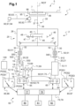
- FIG. 1 presents an example of an aircraft 1 according to the invention.
- This aircraft 1 comprises a rotary wing 5.
- the rotary wing 5 comprises a plurality of blades 6 movable in rotation about an axis of rotation ROT of the rotary wing 5, the blades 6 being for example carried by a hub 7 or equivalent.
- the pitch of the blades 6 can be controlled by a conventional flight control device 90.
- a flight control device 90 can comprise a cyclic pitch lever 91 and a collective pitch lever 94 connected by a linkage system 93 to several servocontrols 92.
- Each servocontrol 92 can be articulated to a swashplate system 95 connected by pitch rods 96 to the respective blades 6.
- the aircraft 1 may comprise at least one door 100 to allow the boarding and disembarkation of people and/or cargo.
- the aircraft 1 comprises a power plant 2 for rotating the rotary wing 5 in order to provide lift, or even advancement, of the aircraft 1.
- This power plant 2 is provided with at least two engines 10.
- the reference 10 designates any engine, the references 11, 12 designating particular engines if necessary to identify a specific engine 10.
- At least one engine 10 may be a turboshaft engine.
- a turboshaft engine 10 comprises a gas generator 15 which is provided with at least one compression turbine 16, a combustion chamber 17 into which the fuel is injected and at least one expansion turbine 18 linked in rotation to the compression turbine(s) 16.
- the turboshaft engine 10 may comprise at least one free turbine 19 which directly or indirectly sets in motion a power shaft 20 of the engine.
- each engine 10 therefore comprises a power shaft 20 connected to a power transmission chain 25.
- the power transmission chain 25 is then connected in the usual manner to the rotary wing 5.
- the reference 20 designates any ... power, the references 21, 22 designating particular power shafts respectively of the two motors 11, 12.
- the power transmission chain 25 may be provided with a power transmission box 26 which is mechanically interposed between the motors 20 and the rotary wing 5.
- the power transmission box 26 comprises a rotor mast 35, provided with one or more collinear shafts 36, 37 connected to the rotary wing 5, and according to the example to the hub 7.
- the power transmission box 26 may be provided with an input shaft 30 per motor 20 and various gears arranged between the input shafts 30 and the rotor mast 35.
- each input shaft 30 is engaged on a large wheel 40. This large wheel 40 is then mechanically connected by an internal shaft 41 to a planetary pinion 46 of a power reduction stage 45.
- Planetary pinions 47 are then engaged on the one hand on the planetary pinion 46 and on a toothed crown 48 stationary in the reference frame of the aircraft.
- the satellite pinions 47 are carried by a planet carrier 49 integral in rotation with the rotor mast 35. From then on, each input shaft 30 is driven in rotation by an output shaft 20 of an engine 10 directly or via a respective mechanical input chain.
- the power transmission chain 25, and according to the example illustrated a mechanical input chain, may comprise at least one freewheel 51, and/or at least one connecting shaft 52, and/or at least one connector allowing misalignments...
- the engines 10 are thermal engines operating with fuel. Therefore, the aircraft 1 has a regulation system 55 to control the power delivered by each motor 10 with its power shaft 20.
- the regulation system 55 comprises a fuel metering device 69 per engine 10. Each engine 10 is then connected via its own fuel metering device 69 to at least one fuel tank 70.
- the reference 69 designates any fuel metering device, the references 71, 72 designating particular fuel metering devices respectively of the two engines 11, 12.
- the regulation system 55 may comprise an engine computer 60 per engine 10.
- Each engine computer 60 may comprise, for example, at least one processor 64 and at least one memory 65, at least one integrated circuit, at least one programmable system, at least one logic circuit, these examples not limiting the scope given to the expression “engine computer”.
- the engine computers may communicate with each other via wired or wireless links.
- the engine installation 2 comprises two engine computers 61, 62 respectively controlling two engines 11, 12.
- Each engine computer is configured to control the associated engine and make it operate according to the required speed, for example so that the controlled engine develops a power tending towards a limit power of this speed.
- Each engine computer 61, 62 can in particular control the fuel metering device 71, 72 of this engine 11, 12.
- Each engine computer 61, 62 can be connected to multiple regulation sensors to control the associated engine 11, 12, such as for example a temperature sensor 930 measuring the gas temperature for example at the inlet of a free turbine, a speed sensor measuring for example the rotation speed of a gas generator of the turboshaft engine, a torque meter 910, 920 measuring an engine torque on a rotating member, a speed sensor 940, 950 measuring for example the rotation speed of this rotating member.
- a rotating member may be a power shaft 20 of an engine 10.
- the power plant 2 may also include regulation sensors comprising a torque meter measuring a torque exerted on the rotor mast 35, a speed sensor measuring for example the rotation speed of this rotor mast 35, a sensor measuring the external pressure, a sensor measuring the external temperature, etc.
- the engine computers 60 can form a controller 75 applying the method of the invention, or a management computer 78 of the regulation system 55 can act as a controller 75 controlling the engine computers 60.
- the management computer 78 can comprise for example at least one processor 76 and at least one memory 77, at least one integrated circuit, at least one programmable system, at least one logic circuit, these examples not limiting the scope given to the expression "management computer”.
- the management computer 78 can communicate by wired or wireless links with each engine computer 60, or can even be merged with at least one engine computer 60.
- the management computer 78 can communicate with each of the aforementioned measurement systems.
- the controller 75 can communicate by a wired or wireless connection with at least one alerter 80 to provide information to a pilot.
- an alerter 80 can, for example, comprise a display capable of displaying a message, a light-emitting diode which lights up on command from the controller 75, a loudspeaker, etc.
- controller 75 may communicate with a stop human-machine interface 82 and/or a selection human-machine interface 81.
- the controller 75 can communicate with a starting human-machine interface 85 per engine, namely two interfaces 86, 87 according to the example given.
- Each starting human-machine interface 85 can for example emit a signal carrying a stop command, an idle speed command or a flight speed command of the engine concerned.
- the figure 1 illustrates three-position interfaces stop POS1/idle POS2/flight POS3 for this purpose.
- Each human-machine interface 81, 82, 85 may include a device that can be operated by a pilot, such as a button or a lever for example, a touch screen, a voice command, etc.
- the human-machine interfaces 81, 82, 85 and the alerter 80 communicate with the management computer 78.
- the human-machine interfaces 81, 82, 85 and the alerter 80 communicate with one or even each engine computer 60.
- FIG 2 illustrates the piloting method according to the invention, this method being able to be implemented by a rotary wing aircraft 1 of the type of the figure 1 .
- the process is illustrated with the use of the control system 55 of the figure 1 .
- this method is applicable with a regulation system devoid of a management computer 78, the engine computers 60 being able to be easily configured to apply it.
- This piloting method involves the implementation on the ground, namely when a landing gear of the aircraft 1 is resting on the ground, of a MODECENER energy-saving phase.
- the method may include STP0 regulation of one or more engines 11, 12 at idle speed.
- STP0 regulation of one or more engines 11, 12 at idle speed.
- the starting man-machine 85 is positioned in the idle position, the engine computer(s) 60 regulating the respective engine(s) 10 to the idle speed on the order of the management computer 78.
- the MODECENER energy-saving phase can be triggered subsequently, for example manually by requesting the selection human-machine interface 81.
- a driver operates the selection human-machine interface 81 which transmits a control signal to the controller 75.
- the controller 75 can be configured to check that one or more required conditions are met, and if necessary triggers the MODECENER energy-saving phase.
- this energy-saving phase MODECENER comprises one or more economic periods STPASY.
- This economic period STPASY comprises the regulation, with the regulation system 55, of an engine 10 called the “active engine” at an active speed, and jointly the stopping or regulation at a rest speed of the other engine(s) called the “non-active engines”.
- the active engine 10 at active speed is controlled by its engine computer 60 to develop a non-zero active driving power PWACT with its power shaft 20.
- This active driving power PWACT can be sufficient on its own to rotate the rotary wing 5, and allow the aircraft 1 to move on the ground with only the active engine 10.
- the active regime can be the idle regime.
- this active driving power PWACT is the idle power PWRAL less than a driving power in PWVOL flight used during at least one usable flight regime during a takeoff phase, in flight and during a landing phase.
- the engine power at idle is less than the maximum continuous power.
- the active regime can be a flight regime.
- the active engine power PWACT is greater than the idle power PWRAL, and equal to an engine power in flight PWVOL or possibly to the maximum continuous power.
- an engine 10 not active at rest speed does not generate any driving power via its power shaft 20, with a gas generator possibly set in motion via an external starter, or produces a non-zero super idle power PWSR possibly with the combustion chamber ignited.
- the super idle power PWSR is lower than the active driving power PWACT, or even the idle power PWRAL.
- the management computer 78 transmits a regulation signal to each engine computer 60 to apply the required speed to each engine 10.
- each engine computer 60 receives the control signal and is configured to apply the required speed accordingly.
- each engine computer 60 controls in particular the associated fuel metering device 69 according to the signals emitted by the regulation sensor(s) so that the controlled engine 10 develops the required driving power with its power shaft 20.
- the MODECENER energy-saving phase also comprises at least one alternating operating phase, the alternating operating phase(s) comprising a period of joint operation STPAEO and an economic period.
- STPASY alternating operating phase
- the joint operation period STPAEO may be carried out before the economic period STPASY as illustrated in dotted lines or after the economic period STPASY as illustrated in solid lines.
- the joint operating period STPAEO includes the regulation, with the regulation system 55, of all the engines 10 at active speed. Each engine 10 at active speed then develops, with its power shaft 20, the active driving power PWACT, and possibly the idle power PWRAL.
- the transition from the joint operating period STPAEO to the economic period STPASY, or vice versa, may be required by the controller 75.
- the controller 75 may be configured to change period at the end of a predetermined duration, and/or following the operation of an interface and for example the stopping human-machine interface 82.
- the MODECENER energy-saving phase can finally be interrupted, for example manually using the start-up human-machine interfaces 85.
- These start-up human-machine interfaces 85 can transmit stop signals to the controller 75 to either stop STPEXT all the engines 10 still in operation by positioning them in the aforementioned POS1 position, or on the contrary require the application of a flight regime with each engine 10 in order to initiate a PHASDEC take-off phase by positioning them in the aforementioned POS3 position.
- the energy-saving phase may be a pre-takeoff phase at the start of the mission followed by a takeoff phase, or an intermediate phase on the ground during the mission preceded by a landing phase and followed by a takeoff phase, or an end-of-mission phase followed by the shutdown of the engines 10.
- FIGS. 3 to 7 illustrate various configurations through diagrams showing a driving power developed by each engine 10 on the ordinate and the time on the abscissa. These examples illustrate in solid lines the power developed by a first engine 11 of a twin-engine aircraft 1 and in broken lines the power developed by a second engine 12 of the aircraft 1. These examples illustrate an active regime of the idle regime type allowing the active engine to develop with its working shaft an active driving power PWACT equal to the idle power PWRAL.
- the active regime can be a regime allowing the active engine to develop with its working shaft an active driving power PWACT greater than the idle power PWRAL, and possibly equal to a flight power.
- FIG 3 illustrates a first example of application of the invention to the start-up of an aircraft 1.
- the first engine 11 is started using its human-machine start-up interface 85 positioned in the “idle” position POS2. If necessary, the human-machine selection interface 81 is operated. The economic period STPASY then begins.
- the first engine 11 provides active driving power, equal to the idle power PWRAL according to the example, sufficient to set the rotary wing 5 in motion.
- the second engine 12 is stopped in the given example but could operate at rest speed, by being previously started by positioning its starting human-machine interface 85 in the “idle” position POS2.
- the joint operation period STPAEO is initiated.
- the first engine 11 and the second engine 12 are controlled to develop the active engine power PWACT, equal to the idle power PWRAL according to the example.
- the takeoff phase PHASDEC is then initiated by positioning the starting human-machine interfaces 85 in the flight position POS3.
- the first engine 11 and the second engine 12 are driven to each develop a flight operating power PWVOL, for example the maximum takeoff power PMD.
- the aircraft 1 takes off and then a flight phase PHASVOL is initiated.
- the first engine 11 and the second engine 12 are driven to develop a flight operating power PWVOL, for example the maximum continuous power PMC.
- the energy-saving phase MODECENER comprises several alternating operating phases PHASALT, each alternating operating phase PHASALT comprising an economical period STPASY followed by a joint operating period STPAEO.
- the transition from one alternating operating phase to another can be obtained at the end of a duration or using the stopping human-machine interface 82 for example.
- the inactive engine 12 is switched off, by the regulation system 55, during the first alternating operating phase P1, and at rest speed to develop a non-zero PWSR power during the second phase(s) of alternating operation P2.
- each engine 10 operates according to a flight regime, for example by developing the maximum continuous power PMC.
- the starting human-machine interfaces 85 are positioned in the “idle” position.
- a joint operation period STPAEO is thus implemented.
- the energy-saving phase MODECENER is then triggered, for example by operating the selection human-machine interface 81.
- the first engine 11 is controlled by its engine computer 61 to become the active engine 10 requested during the economy period STPASY.
- the first engine 11 provides the active engine power PWACT, equal to the idle power PWRAL according to the example.
- the second engine 12 is in the example given stopped but could operate at rest speed by being regulated by its engine computer 62. Under predetermined conditions, the joint operation period STPAEO is triggered, for example by operating the shutdown human-machine interface 82.
- the first engine 11 and the second engine 12 are controlled by the engine computers 61, 62 to develop the active engine power PWACT, equal to the idle power PWRAL according to the example.
- the takeoff phase PHASDEC is then triggered.
- the first engine 11 and the second engine 12 are controlled to develop an in-flight operating power PWVOL, for example the maximum takeoff power PMD.
- each engine 10 operates according to a flight regime, for example by developing the maximum continuous power PMC.
- the starting human-machine interfaces 85 are positioned in the “idle” position.
- the energy-saving phase MODECENER is then engaged, for example by operating the selection human-machine interface 81.
- the first engine 11 is controlled to become the active engine 10 requested during the economic period STPASY.
- the first engine 11 provides the active engine power PWACT, equal to the idle power PWRAL according to the example.
- the second engine 12 is stopped in the given example but could operate at rest speed. Under predetermined conditions, the stopping of all the engines 10 is initiated, for example by operating the starting human-machine interfaces 85 to position them in the stop position POS1.
- the energy-saving phase MODECENER comprises several alternating operating phases PHASALT, each alternating operating phase PHASALT comprising a joint operating period STPAEO followed by an economical period STPASY.
Landscapes
- Engineering & Computer Science (AREA)
- Aviation & Aerospace Engineering (AREA)
- Mechanical Engineering (AREA)
- Chemical & Material Sciences (AREA)
- Combustion & Propulsion (AREA)
- General Engineering & Computer Science (AREA)
- Control Of Vehicle Engines Or Engines For Specific Uses (AREA)
- Output Control And Ontrol Of Special Type Engine (AREA)
Applications Claiming Priority (1)
| Application Number | Priority Date | Filing Date | Title |
|---|---|---|---|
| FR2303657A FR3147793A1 (fr) | 2023-04-13 | 2023-04-13 | procédé de pilotage d’un aéronef à voilure tournante multimoteur à consommation de carburant réduite au sol |
Publications (2)
| Publication Number | Publication Date |
|---|---|
| EP4446232A1 true EP4446232A1 (de) | 2024-10-16 |
| EP4446232B1 EP4446232B1 (de) | 2025-06-11 |
Family
ID=87136500
Family Applications (1)
| Application Number | Title | Priority Date | Filing Date |
|---|---|---|---|
| EP24153732.3A Active EP4446232B1 (de) | 2023-04-13 | 2024-01-24 | Verfahren zur steuerung eines mehrmotorigen drehflügelflugzeugs mit reduziertem bodenverbrauch |
Country Status (3)
| Country | Link |
|---|---|
| US (1) | US12466569B2 (de) |
| EP (1) | EP4446232B1 (de) |
| FR (1) | FR3147793A1 (de) |
Families Citing this family (1)
| Publication number | Priority date | Publication date | Assignee | Title |
|---|---|---|---|---|
| FR3147793A1 (fr) * | 2023-04-13 | 2024-10-18 | Airbus Helicopters | procédé de pilotage d’un aéronef à voilure tournante multimoteur à consommation de carburant réduite au sol |
Citations (6)
| Publication number | Priority date | Publication date | Assignee | Title |
|---|---|---|---|---|
| FR2871138A1 (fr) | 2004-06-07 | 2005-12-09 | Eurocopter France | Mecanisme de transmission entre des accessoires et les organes moteurs d'entrainement du rotor d'un giravion, selectivement isolement ou conjointement |
| FR2967132B1 (fr) | 2010-11-04 | 2012-11-09 | Turbomeca | Procede d'optimisation de la consommation specifique d'un helicoptere bimoteur et architecture bimoteur dissymetrique a systeme de regulation pour sa mise en oeuvre |
| EP2735512A1 (de) | 2012-11-26 | 2014-05-28 | Airbus Helicopters | Verfahren und Hubschrauber mit drei Triebwerken |
| FR3001525A1 (fr) | 2013-01-29 | 2014-08-01 | Turbomeca | Procede de gestion de la consommation de carburant d un ensemble bimoteur et ensemble associe |
| FR3011587A1 (fr) | 2013-10-09 | 2015-04-10 | Turbomeca | Procede d'optimisation de la consommation specifique d'un helicoptere bimoteur |
| US20180187604A1 (en) | 2014-03-27 | 2018-07-05 | Safran Helicopter Engines | Assistance device for a free-turbine engine of an aircraft having at least two free-turbine engines |
Family Cites Families (8)
| Publication number | Priority date | Publication date | Assignee | Title |
|---|---|---|---|---|
| FR3019219B1 (fr) * | 2014-03-27 | 2016-03-18 | Turbomeca | Architecture d'un systeme propulsif d'un helicoptere multi-moteur et helicoptere correspondant |
| FR3034403B1 (fr) * | 2015-03-31 | 2017-03-31 | Airbus Helicopters | Procede et dispositif pour arreter un turbomoteur en fonctionnement nominal |
| US11274599B2 (en) * | 2019-03-27 | 2022-03-15 | Pratt & Whitney Canada Corp. | Air system switching system to allow aero-engines to operate in standby mode |
| US11274611B2 (en) * | 2019-05-31 | 2022-03-15 | Pratt & Whitney Canada Corp. | Control logic for gas turbine engine fuel economy |
| US11859563B2 (en) * | 2019-05-31 | 2024-01-02 | Pratt & Whitney Canada Corp. | Air system of multi-engine aircraft |
| US11663863B2 (en) * | 2019-06-07 | 2023-05-30 | Pratt & Whitney Canada Corp. | Methods and systems for operating a rotorcraft |
| US11554874B2 (en) * | 2020-10-02 | 2023-01-17 | Pratt & Whitney Canada Corp. | Method and system for governing an engine at low power |
| FR3147793A1 (fr) * | 2023-04-13 | 2024-10-18 | Airbus Helicopters | procédé de pilotage d’un aéronef à voilure tournante multimoteur à consommation de carburant réduite au sol |
-
2023
- 2023-04-13 FR FR2303657A patent/FR3147793A1/fr active Pending
-
2024
- 2024-01-24 EP EP24153732.3A patent/EP4446232B1/de active Active
- 2024-02-14 US US18/441,489 patent/US12466569B2/en active Active
Patent Citations (7)
| Publication number | Priority date | Publication date | Assignee | Title |
|---|---|---|---|---|
| FR2871138A1 (fr) | 2004-06-07 | 2005-12-09 | Eurocopter France | Mecanisme de transmission entre des accessoires et les organes moteurs d'entrainement du rotor d'un giravion, selectivement isolement ou conjointement |
| FR2967132B1 (fr) | 2010-11-04 | 2012-11-09 | Turbomeca | Procede d'optimisation de la consommation specifique d'un helicoptere bimoteur et architecture bimoteur dissymetrique a systeme de regulation pour sa mise en oeuvre |
| FR2967133B1 (fr) | 2010-11-04 | 2012-11-16 | Turbomeca | Procede d'optimisation de la consommation specifique d'un helicoptere bimoteur et architecture bimoteur a systeme de regulation pour sa mise en oeuvre |
| EP2735512A1 (de) | 2012-11-26 | 2014-05-28 | Airbus Helicopters | Verfahren und Hubschrauber mit drei Triebwerken |
| FR3001525A1 (fr) | 2013-01-29 | 2014-08-01 | Turbomeca | Procede de gestion de la consommation de carburant d un ensemble bimoteur et ensemble associe |
| FR3011587A1 (fr) | 2013-10-09 | 2015-04-10 | Turbomeca | Procede d'optimisation de la consommation specifique d'un helicoptere bimoteur |
| US20180187604A1 (en) | 2014-03-27 | 2018-07-05 | Safran Helicopter Engines | Assistance device for a free-turbine engine of an aircraft having at least two free-turbine engines |
Also Published As
| Publication number | Publication date |
|---|---|
| US20240343404A1 (en) | 2024-10-17 |
| EP4446232B1 (de) | 2025-06-11 |
| FR3147793A1 (fr) | 2024-10-18 |
| US12466569B2 (en) | 2025-11-11 |
Similar Documents
| Publication | Publication Date | Title |
|---|---|---|
| EP2735512B1 (de) | Verfahren und hubschrauber mit drei triebwerken | |
| CA3064098C (fr) | Procede d'assistance pour aeronef monomoteur a voilure tournante lors d'une panne moteur | |
| EP3095695B1 (de) | Betätigungsverfahren eines elektromotors einer hybridanlage eines mehrmotorigen luftfahrzeugs, und entsprechendes luftfahrzeug | |
| CA3070485C (fr) | Procede d'optimisation du bruit genere au sol par un giravion | |
| CA2943618C (fr) | Turbomoteur comprenant un dispositif de couplage mecanique commande, helicoptere equipe d'un tel turbomoteur et procede d'optimisation du regime de super-ralenti a puissance nulle d'un tel helicoptere | |
| EP4259521B1 (de) | Hybrides antriebssystem für einen hubschrauber | |
| FR2952907A1 (fr) | Installation motrice, helicoptere comportant une telle installation motrice, et procede mis en oeuvre par cette installation motrice | |
| EP3109156B1 (de) | Regulierverfahren für eine dreimotorige antriebsanlage für ein drehflügelflugzeug | |
| CA3076773A1 (fr) | Procede d'optimisation du bruit genere en vol par un giravion | |
| FR2950324A1 (fr) | Procede et dispositif d'aide au pilotage d'un aeronef en cas de pannes d'un indicateur de premiere limitation | |
| EP2508735B1 (de) | Verfahren und Vorrichtung für die Betriebssteuerung der Motoren eines Luftfahrzeugs während der Startphase | |
| CA2799712C (fr) | Dispositif et procede de regulation d'une installation motrice comportant au moins un turbomoteur, et aeronef | |
| EP4446232B1 (de) | Verfahren zur steuerung eines mehrmotorigen drehflügelflugzeugs mit reduziertem bodenverbrauch | |
| EP3932804B1 (de) | System und verfahren zur unterstützung der synchronisation eines freilaufs und entsprechendes fahrzeug | |
| CA2756310C (fr) | Installation motrice d'un aeronef, aeronef, et procede de pilotage dudit aeronef | |
| EP4253248A1 (de) | Propellerflugzeug | |
| EP4563470A1 (de) | Verfahren zum antrieb eines hybridmotorisierten drehflügelflugzeugs mit motorausfall | |
| FR3078681A1 (fr) | Procede pour pallier un deficit de puissance en cas de panne d'un moteur sur un aeronef a voilure tournante multimoteur |
Legal Events
| Date | Code | Title | Description |
|---|---|---|---|
| PUAI | Public reference made under article 153(3) epc to a published international application that has entered the european phase |
Free format text: ORIGINAL CODE: 0009012 |
|
| STAA | Information on the status of an ep patent application or granted ep patent |
Free format text: STATUS: THE APPLICATION HAS BEEN PUBLISHED |
|
| AK | Designated contracting states |
Kind code of ref document: A1 Designated state(s): AL AT BE BG CH CY CZ DE DK EE ES FI FR GB GR HR HU IE IS IT LI LT LU LV MC ME MK MT NL NO PL PT RO RS SE SI SK SM TR |
|
| STAA | Information on the status of an ep patent application or granted ep patent |
Free format text: STATUS: REQUEST FOR EXAMINATION WAS MADE |
|
| 17P | Request for examination filed |
Effective date: 20241017 |
|
| RBV | Designated contracting states (corrected) |
Designated state(s): AL AT BE BG CH CY CZ DE DK EE ES FI FR GB GR HR HU IE IS IT LI LT LU LV MC ME MK MT NL NO PL PT RO RS SE SI SK SM TR |
|
| P01 | Opt-out of the competence of the unified patent court (upc) registered |
Free format text: CASE NUMBER: APP_56798/2024 Effective date: 20241017 |
|
| GRAP | Despatch of communication of intention to grant a patent |
Free format text: ORIGINAL CODE: EPIDOSNIGR1 |
|
| STAA | Information on the status of an ep patent application or granted ep patent |
Free format text: STATUS: GRANT OF PATENT IS INTENDED |
|
| INTG | Intention to grant announced |
Effective date: 20250314 |
|
| GRAS | Grant fee paid |
Free format text: ORIGINAL CODE: EPIDOSNIGR3 |
|
| GRAA | (expected) grant |
Free format text: ORIGINAL CODE: 0009210 |
|
| STAA | Information on the status of an ep patent application or granted ep patent |
Free format text: STATUS: THE PATENT HAS BEEN GRANTED |
|
| AK | Designated contracting states |
Kind code of ref document: B1 Designated state(s): AL AT BE BG CH CY CZ DE DK EE ES FI FR GB GR HR HU IE IS IT LI LT LU LV MC ME MK MT NL NO PL PT RO RS SE SI SK SM TR |
|
| REG | Reference to a national code |
Ref country code: GB Ref legal event code: FG4D Free format text: NOT ENGLISH |
|
| REG | Reference to a national code |
Ref country code: CH Ref legal event code: EP |
|
| REG | Reference to a national code |
Ref country code: DE Ref legal event code: R096 Ref document number: 602024000183 Country of ref document: DE |
|
| REG | Reference to a national code |
Ref country code: IE Ref legal event code: FG4D Free format text: LANGUAGE OF EP DOCUMENT: FRENCH |
|
| PG25 | Lapsed in a contracting state [announced via postgrant information from national office to epo] |
Ref country code: FI Free format text: LAPSE BECAUSE OF FAILURE TO SUBMIT A TRANSLATION OF THE DESCRIPTION OR TO PAY THE FEE WITHIN THE PRESCRIBED TIME-LIMIT Effective date: 20250611 Ref country code: ES Free format text: LAPSE BECAUSE OF FAILURE TO SUBMIT A TRANSLATION OF THE DESCRIPTION OR TO PAY THE FEE WITHIN THE PRESCRIBED TIME-LIMIT Effective date: 20250611 |
|
| REG | Reference to a national code |
Ref country code: LT Ref legal event code: MG9D |
|
| PG25 | Lapsed in a contracting state [announced via postgrant information from national office to epo] |
Ref country code: GR Free format text: LAPSE BECAUSE OF FAILURE TO SUBMIT A TRANSLATION OF THE DESCRIPTION OR TO PAY THE FEE WITHIN THE PRESCRIBED TIME-LIMIT Effective date: 20250912 Ref country code: NO Free format text: LAPSE BECAUSE OF FAILURE TO SUBMIT A TRANSLATION OF THE DESCRIPTION OR TO PAY THE FEE WITHIN THE PRESCRIBED TIME-LIMIT Effective date: 20250911 |
|
| REG | Reference to a national code |
Ref country code: NL Ref legal event code: MP Effective date: 20250611 |
|
| PG25 | Lapsed in a contracting state [announced via postgrant information from national office to epo] |
Ref country code: BG Free format text: LAPSE BECAUSE OF FAILURE TO SUBMIT A TRANSLATION OF THE DESCRIPTION OR TO PAY THE FEE WITHIN THE PRESCRIBED TIME-LIMIT Effective date: 20250611 |
|
| PG25 | Lapsed in a contracting state [announced via postgrant information from national office to epo] |
Ref country code: HR Free format text: LAPSE BECAUSE OF FAILURE TO SUBMIT A TRANSLATION OF THE DESCRIPTION OR TO PAY THE FEE WITHIN THE PRESCRIBED TIME-LIMIT Effective date: 20250611 |
|
| PG25 | Lapsed in a contracting state [announced via postgrant information from national office to epo] |
Ref country code: RS Free format text: LAPSE BECAUSE OF FAILURE TO SUBMIT A TRANSLATION OF THE DESCRIPTION OR TO PAY THE FEE WITHIN THE PRESCRIBED TIME-LIMIT Effective date: 20250911 |
|
| PG25 | Lapsed in a contracting state [announced via postgrant information from national office to epo] |
Ref country code: LV Free format text: LAPSE BECAUSE OF FAILURE TO SUBMIT A TRANSLATION OF THE DESCRIPTION OR TO PAY THE FEE WITHIN THE PRESCRIBED TIME-LIMIT Effective date: 20250611 |
|
| PG25 | Lapsed in a contracting state [announced via postgrant information from national office to epo] |
Ref country code: NL Free format text: LAPSE BECAUSE OF FAILURE TO SUBMIT A TRANSLATION OF THE DESCRIPTION OR TO PAY THE FEE WITHIN THE PRESCRIBED TIME-LIMIT Effective date: 20250611 |
|
| PG25 | Lapsed in a contracting state [announced via postgrant information from national office to epo] |
Ref country code: PT Free format text: LAPSE BECAUSE OF FAILURE TO SUBMIT A TRANSLATION OF THE DESCRIPTION OR TO PAY THE FEE WITHIN THE PRESCRIBED TIME-LIMIT Effective date: 20251013 |
|
| REG | Reference to a national code |
Ref country code: AT Ref legal event code: MK05 Ref document number: 1802173 Country of ref document: AT Kind code of ref document: T Effective date: 20250611 |
|
| PG25 | Lapsed in a contracting state [announced via postgrant information from national office to epo] |
Ref country code: IS Free format text: LAPSE BECAUSE OF FAILURE TO SUBMIT A TRANSLATION OF THE DESCRIPTION OR TO PAY THE FEE WITHIN THE PRESCRIBED TIME-LIMIT Effective date: 20251011 |
|
| PG25 | Lapsed in a contracting state [announced via postgrant information from national office to epo] |
Ref country code: SM Free format text: LAPSE BECAUSE OF FAILURE TO SUBMIT A TRANSLATION OF THE DESCRIPTION OR TO PAY THE FEE WITHIN THE PRESCRIBED TIME-LIMIT Effective date: 20250611 Ref country code: AT Free format text: LAPSE BECAUSE OF FAILURE TO SUBMIT A TRANSLATION OF THE DESCRIPTION OR TO PAY THE FEE WITHIN THE PRESCRIBED TIME-LIMIT Effective date: 20250611 |
|
| PG25 | Lapsed in a contracting state [announced via postgrant information from national office to epo] |
Ref country code: CZ Free format text: LAPSE BECAUSE OF FAILURE TO SUBMIT A TRANSLATION OF THE DESCRIPTION OR TO PAY THE FEE WITHIN THE PRESCRIBED TIME-LIMIT Effective date: 20250611 |
|
| PG25 | Lapsed in a contracting state [announced via postgrant information from national office to epo] |
Ref country code: PL Free format text: LAPSE BECAUSE OF FAILURE TO SUBMIT A TRANSLATION OF THE DESCRIPTION OR TO PAY THE FEE WITHIN THE PRESCRIBED TIME-LIMIT Effective date: 20250611 |
|
| PG25 | Lapsed in a contracting state [announced via postgrant information from national office to epo] |
Ref country code: EE Free format text: LAPSE BECAUSE OF FAILURE TO SUBMIT A TRANSLATION OF THE DESCRIPTION OR TO PAY THE FEE WITHIN THE PRESCRIBED TIME-LIMIT Effective date: 20250611 |
|
| PG25 | Lapsed in a contracting state [announced via postgrant information from national office to epo] |
Ref country code: SK Free format text: LAPSE BECAUSE OF FAILURE TO SUBMIT A TRANSLATION OF THE DESCRIPTION OR TO PAY THE FEE WITHIN THE PRESCRIBED TIME-LIMIT Effective date: 20250611 |