EP4446230A1 - Ensemble propulsif a capot moteur ameliore, et aeronef comprenant un tel ensemble - Google Patents
Ensemble propulsif a capot moteur ameliore, et aeronef comprenant un tel ensemble Download PDFInfo
- Publication number
- EP4446230A1 EP4446230A1 EP24168907.4A EP24168907A EP4446230A1 EP 4446230 A1 EP4446230 A1 EP 4446230A1 EP 24168907 A EP24168907 A EP 24168907A EP 4446230 A1 EP4446230 A1 EP 4446230A1
- Authority
- EP
- European Patent Office
- Prior art keywords
- engine
- rotation
- aircraft
- pylon
- axis
- Prior art date
- Legal status (The legal status is an assumption and is not a legal conclusion. Google has not performed a legal analysis and makes no representation as to the accuracy of the status listed.)
- Pending
Links
Images
Classifications
-
- B—PERFORMING OPERATIONS; TRANSPORTING
- B64—AIRCRAFT; AVIATION; COSMONAUTICS
- B64D—EQUIPMENT FOR FITTING IN OR TO AIRCRAFT; FLIGHT SUITS; PARACHUTES; ARRANGEMENT OR MOUNTING OF POWER PLANTS OR PROPULSION TRANSMISSIONS IN AIRCRAFT
- B64D27/00—Arrangement or mounting of power plants in aircraft; Aircraft characterised by the type or position of power plants
- B64D27/40—Arrangements for mounting power plants in aircraft
- B64D27/404—Suspension arrangements specially adapted for supporting vertical loads
-
- B—PERFORMING OPERATIONS; TRANSPORTING
- B64—AIRCRAFT; AVIATION; COSMONAUTICS
- B64D—EQUIPMENT FOR FITTING IN OR TO AIRCRAFT; FLIGHT SUITS; PARACHUTES; ARRANGEMENT OR MOUNTING OF POWER PLANTS OR PROPULSION TRANSMISSIONS IN AIRCRAFT
- B64D29/00—Power-plant nacelles, fairings or cowlings
- B64D29/06—Attaching of nacelles, fairings or cowlings
-
- B—PERFORMING OPERATIONS; TRANSPORTING
- B64—AIRCRAFT; AVIATION; COSMONAUTICS
- B64D—EQUIPMENT FOR FITTING IN OR TO AIRCRAFT; FLIGHT SUITS; PARACHUTES; ARRANGEMENT OR MOUNTING OF POWER PLANTS OR PROPULSION TRANSMISSIONS IN AIRCRAFT
- B64D27/00—Arrangement or mounting of power plants in aircraft; Aircraft characterised by the type or position of power plants
- B64D27/02—Aircraft characterised by the type or position of power plants
-
- B—PERFORMING OPERATIONS; TRANSPORTING
- B64—AIRCRAFT; AVIATION; COSMONAUTICS
- B64D—EQUIPMENT FOR FITTING IN OR TO AIRCRAFT; FLIGHT SUITS; PARACHUTES; ARRANGEMENT OR MOUNTING OF POWER PLANTS OR PROPULSION TRANSMISSIONS IN AIRCRAFT
- B64D29/00—Power-plant nacelles, fairings or cowlings
- B64D29/02—Power-plant nacelles, fairings or cowlings associated with wings
-
- B—PERFORMING OPERATIONS; TRANSPORTING
- B64—AIRCRAFT; AVIATION; COSMONAUTICS
- B64D—EQUIPMENT FOR FITTING IN OR TO AIRCRAFT; FLIGHT SUITS; PARACHUTES; ARRANGEMENT OR MOUNTING OF POWER PLANTS OR PROPULSION TRANSMISSIONS IN AIRCRAFT
- B64D29/00—Power-plant nacelles, fairings or cowlings
- B64D29/08—Inspection panels for power plants
Definitions
- the present invention relates to an aircraft propulsion assembly comprising an improved aircraft engine cowling device.
- the invention relates more particularly to an arrangement of hinges and hinge pin(s) of at least one engine cowling of an aircraft propulsion assembly.
- turbofan engines comprising an internal part, which comprises a primary flow path of a power turbine, and an external part which comprises a secondary flow path around the power turbine.
- the internal and external parts are arranged concentrically with respect to each other, the internal part being arranged internally to the external part, and the latter therefore being arranged peripherally to the internal part.
- An engine pylon allows the attachment of such a turbofan engine under the wing of the aircraft equipped with it, and an engine fairing, composed of fixed cowls and removable or articulated cowls, surrounds most of these elements for protection purposes and so as to obtain good aerodynamic performance of the aircraft.
- movable engine hoods are hinged around hinges.
- the hinges are mainly arranged by an assembly of fittings around an axis.
- the fittings of a movable hood are often arranged in the form of a "swan neck" to provide an offset allowing an advantageous trajectory of a movable hood compared to fixed elements of the assembly.
- Engine architectures have been designed and produced, in particular for the purposes of weight reduction, performance improvement, and carbon emissions reduction.
- One of these recent architectures is called the "Turboprop" type, and corresponds to an engine assembly having an unducted fan in which the fan fixed directly to the power turbine (internal part of the dual-flow engine) is arranged outside the nacelle, the nacelle then comprising only the internal part, around of the primary flow.
- the overall shape of a turboprop engine is therefore different from that of a dual-flow engine as mentioned above and the entire engine fairing is therefore also different, which implies structural modifications, particularly for the arrangement of the cowls, and in particular the hinged cowls of an engine.
- An object of the present invention is to offer arrangement possibilities limiting as much as possible the structural modifications of an aircraft with a view to fixing turboprop type engines under the wing.
- an aircraft propulsion unit comprising an engine pylon having an overall box shape and an upper face, an internal engine part, and at least one engine cowl articulated in rotation about an axis of rotation defined by at least two articulation hinges, the aircraft propulsion unit being configured such that the axis of rotation of said at least two articulation hinges of the articulated engine cowl is positioned above said upper face of said engine pylon.
- Another object of the invention is an aircraft comprising at least one aircraft propulsion unit as previously described.
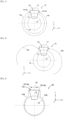
- FIG. 1 An aircraft turbofan engine arrangement is symbolically described, viewed from the front, in relation to the Fig. 1 .
- This arrangement comprises a boxed engine mast 12 configured for the underwing attachment of a dual-flow engine and its dual-flow engine fairing.
- fairing here designates all of the cowling elements and any casings that form the external aerodynamic profile of the engine.
- the assembly thus arranged (the engine, its fairing and the engine mast) is here called the aircraft propulsion unit 10.
- the central longitudinal axis of the aircraft propulsion unit 10 is parallel to a reference axis X.
- a Y axis perpendicular to the X axis defines a transverse direction and a Z axis, perpendicular to the X axis and the Y axis, defines a vertical direction whose abscissa values increase upwards.
- Such an orthonormal X, Y, Z reference frame is conventionally used as a reference for the mechanical arrangement of aircraft and in particular airplanes when they are placed on ground considered to be horizontal (for the definition of the Z axis, vertical).
- the aircraft propulsion assembly 10 comprises the engine pylon 12 which carries internal 13 and external 16 parts of the shown dual-flow aircraft engine.
- the engine pylon 12 is a so-called “boxed” or “cassette” pylon in that it has an overall box shape, as opposed to a lattice pylon structure.
- the internal 13 and external 16 parts of the dual-flow engine are arranged concentrically with respect to one another.
- the upper part of the engine pylon 12 is covered with a fixed upper cowling 15.
- the fixed upper cowling 15 does not exist and the “inner” edges of the removable side engine cowlings are arranged edge to edge or separated by a simple gap, in the upper part of the propulsion unit 10.
- the internal 13 and external 16 parts of the aircraft propulsion unit 10 are covered by two hinged engine cowls 14a and 14b.
- the hinged engine cowl 14a is arranged on one side of the engine relative to the central longitudinal axis of the engine, and the hinged cowl 14b is arranged on the other side of the central longitudinal axis, relative to the hinged engine cowl 14a.
- the engine cowl 14a is hinged in rotation about an axis of rotation (or articulation axis) defined by at least two hinges 1514a, and therefore by hinge fittings carrying these hinges 1514a.
- the engine cowling 14b is hinged in rotation about an axis of rotation (or articulation axis) defined by at least two hinges 1514b, and therefore by hinge fittings carrying these hinges 1514b.
- the engine pylon 12 comprises an upper face 12t.
- the term upper face here designates a high face, or a face oriented in the direction of the increasing abscissa values along the vertical axis Z.
- the upper face 12t is defined by the shape of the upper spar of the primary structure box of the engine pylon 12.
- three hinges 1514a and three hinges 1514b respectively define 1514' and 1514" rotation axes (visible on the Fig. 5b ) of the hinged engine covers 14a and 14b.
- the Fig. 2 illustrates the aircraft propulsion assembly 10 when the hinged engine cowls 14a and 14b of the aircraft propulsion assembly 10 are in the open position. In the illustrated example, the engine cowl 14a is fully open and the engine cowl 14b is open in an intermediate or “half-open” position.
- FIG. 3 An aircraft propulsion unit 30, of the turboprop type, is described in relation to the Fig. 3 , according to one embodiment.
- This turboprop engine architecture differs in particular from the previously described dual-flow architecture due to the absence of a fan fairing, referred to above as the external part 16 of the propulsion unit.
- the secondary flow of the engine is open to any external engine fairing, fixed engine cowl or articulated engine cowl, and these elements are arranged directly around the internal part 13 of the aircraft propulsion unit 30.
- the hinges and therefore the rotation axes of the engine cowls 14a and 14b are positioned above the upper surface 12t of the engine pylon 12, i.e. above a surface defined by the shape of the upper spar of the engine pylon box 12.
- the fairing portions that are substantially vertical and lateral to the engine pylon 12 are included in the articulated engine cowls 14a and 14b, and it is possible to arrange the articulated engine cowls while retaining the overall architecture of the engine pylon 12 and satisfying the engine fairing (or cowling) constraints specific to the shape of the internal part 13 of the aircraft propulsion unit 30. Such an arrangement also avoids conflicts in the positioning of certain movable elements of the articulated engine cowls 14a and 14b (for example swan-neck fittings) with fixed elements present.
- Fig. 4 illustrates the aircraft propulsion assembly 30 when the engine cowls 14a and 14b of the aircraft propulsion assembly 30 are in the open position. In the illustrated example, the hinged engine cowl 14a is fully open and the hinged engine cowl 14b is open in an intermediate or semi-open position.
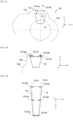
- FIG. 5a illustrates a positioning of the hinges 1514a and 1514b and therefore of the hinge axes 1514' and 1514" above the face 12t of the engine mast, according to an arrangement of the hinge fittings, according to a first embodiment.
- Fig. 5b illustrates symbolically and in a top view this positioning of the hinges 1514a and 1514b and therefore of the hinge axes 1514' and 1514" above the face 12t of the engine pylon.
- the axes 1514' and 1514" of rotation of the engine cowlings are not parallel to each other when the lateral faces of the engine pylon 12 are not parallel to each other (which is the case according to the implementation example illustrated in the Fig. 5b ).
- the fittings of the hinges 1514a and 1514b are respectively arranged on the upper face 12t of the engine mast 12 towards the outside, that is to say being close to the edges which respectively delimit the upper face 12t with each of the two lateral faces of the engine mast 12.
- Fig. 5a only represents the engine cover 14a.
- Fig. 6 and Fig. 7 The same applies to the Fig. 6 and Fig. 7 .
- FIG. 6 illustrates a positioning of the hinges and therefore of the hinge axes above the face 12t of the engine mast, according to an arrangement of the hinge fittings according to a second embodiment.
- the hinges 1514a and 1514b are brought closer in the central part of the upper surface 12t of the engine mast 12, in a higher position than according to the embodiment previously described in relation to the Fig. 5a .
- a higher position characterized by a distance greater than a predetermined threshold value between each of the axes of rotation of the articulated engine cowls 14a and 14b and the upper face of the engine pylon 12t, makes it possible to position oneself as close as possible to the aerodynamic skin and to avoid position conflicts between the articulated mobile elements and the fixed parts present while retaining the overall architecture of the engine pylon 12.
- the terms “overall architecture of the engine pylon 12” here designate the shape and dimensions of the structure of the engine pylon relating in particular to the primary structure of the aircraft, and outside the hinge fittings of the articulated engine cowls.
- FIG. 7 illustrates a positioning of the hinges 1514a and 1514b, and therefore of the hinge axes 1514' and 1514", above the face 12t of the engine pylon, according to an arrangement of the hinge fittings according to a third embodiment.
- the two hinge axes (or axes of rotation of the articulated engine cowls 14a and 14b) are merged to form only one common articulation axis for the two engine cowls 14a and 14b.
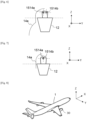
- FIG. 8 illustrates an aircraft 1 advantageously comprising at least one propulsion unit 30.
- the hinged engine hoods 14a and 14b, as well as the fixed upper cowling 15 can be fitted with sealing elements configured to ensure a seal between the inside and the outside of the cowling, when the hinged engine hoods 14a and 14b are closed, for example seals at the edge of the engine hoods.
Landscapes
- Engineering & Computer Science (AREA)
- Aviation & Aerospace Engineering (AREA)
- Structures Of Non-Positive Displacement Pumps (AREA)
Abstract
L'invention concerne un ensemble propulsif (30) d'aéronef comprenant un mât moteur (12) présentant une face supérieure (12t), une partie interne de moteur (13), un éventuel capotage supérieur fixe (15) du mât moteur (12) et au moins un capot moteur (14a) articulé en rotation selon un axe de rotation (1514') défini par au moins deux charnières d'articulation (1514a), ledit ensemble propulsif (30) d'aéronef étant configuré de sorte que ledit axe de rotation (1514') desdites au moins deux charnières d'articulation (1514a) est positionné au-dessus de ladite face supérieure (12t) dudit mât moteur (12).Avantageusement, il est ainsi possible d'assembler un carénage de nacelle autour de la partie interne (13) du moteur, en l'absence de la partie externe constituée du carénage de soufflante, et sans modifier la structure du mât moteur (12) hormis pour ce qui concerne l'agencement des ferrures de charnières des capots moteurs mobiles.
Description
- La présente invention concerne un ensemble propulsif d' aéronef comprenant un dispositif amélioré de capotage de moteur d'aéronef. L'invention concerne plus particulièrement un agencement de charnières et d'axe(s) de charnières d'au moins un capot moteur d'un ensemble propulsif d'aéronef.
- De nombreux aéronefs sont équipés de moteurs à double flux comprenant une partie interne, laquelle comprend une veine primaire d'une turbine de puissance, et une partie externe laquelle comprend une veine secondaire autour de la turbine de puissance. Dans une telle configuration, les parties interne et externe sont agencées concentriquement l'une par rapport à l'autre, la partie interne étant agencée intérieurement à la partie externe, et cette dernière étant donc agencée de façon périphérique à la partie interne. Un mât moteur permet la fixation d'un tel moteur à double flux sous la voilure de l'aéronef qui en est équipé, et un carénage moteur, composé de capots fixes et de capots amovibles ou articulés, entoure l'essentiel de ces éléments à des fins de protection et de sorte à obtenir de bonnes performances aérodynamiques de l'aéronef. Un accès aux éléments d'un moteur est nécessaire à la réalisation d'opérations d'assemblage, de contrôles et de maintenance et des capots moteur articulés sont agencés de sorte à pouvoir être aisément ouverts ou fermés. Très souvent, les capots moteur mobiles sont articulés autour de charnières. Les charnières sont principalement agencées par un assemblage de ferrures autour d'un axe. Les ferrures d'un capot mobile sont souvent agencées sous forme d'un « col de cygne » pour offrir un déport permettant une trajectoire avantageuse d'un capot mobile par rapport à des éléments fixes de l'ensemble.
- Des architectures de moteurs ont été conçues et réalisées, notamment à des fins d'allégement du poids, d'amélioration de la performance, et de réduction d'émissions carbonées. L'une de ces architectures récentes est dite de type « Turbopropulseur », et correspond à un ensemble moteur présentant une soufflante non carénée dans lequel la soufflante fixée directement sur la turbine de puissance (partie interne du moteur double flux) est agencée en dehors de la nacelle, la nacelle ne comprenant alors que la partie interne, autour du flux primaire. La forme globale d'un moteur de type Turbopropulseur est donc différente de celle d'un moteur à double flux tel que susmentionné et l'ensemble du carénage moteur est en conséquence différent lui aussi, ce qui implique des modifications structurelles notamment pour l'agencement des capots, et en particulier des capots articulés d'un moteur.
- Il existe donc un besoin d'agencer ces différents éléments d'un ensemble propulsif d'aéronef de type turbopropulseur sans avoir à modifier des éléments structurels comme la structure principale du mât moteur, par exemple, ainsi que la fixation du mât moteur sous la voilure ou en modifiant ces éléments a minima.
- Un objet de la présente invention est d'offrir des possibilités d'agencement limitant au maximum les modifications structurelles d'un aéronef en vue de la fixation sous voilure de moteurs de type turbopropulseur.
- A cet effet, il est proposé un ensemble propulsif d'aéronef comprenant un mât moteur présentant une forme globale de caisson et une face supérieure, une partie interne de moteur, et au moins un capot moteur articulé en rotation selon un axe de rotation défini par au moins deux charnières d'articulation, l'ensemble propulsif d'aéronef étant configuré de sorte que l'axe de rotation desdites au moins deux charnières d'articulation du capot moteur articulé est positionné au-dessus de ladite face supérieure dudit mât moteur.
- L'ensemble propulsif d'aéronef selon l'invention peut comprendre en outre les caractéristiques suivantes, considérées seules ou en combinaison :
- L'ensemble propulsif comprend en outre un deuxième capot moteur respectivement articulé en rotation autour d'un deuxième axe de rotation défini par au moins deux autres charnières d'articulation et positionné au-dessus de ladite face supérieure.
- Les deux axes de rotation desdits capots moteur de l'ensemble propulsif sont disposés parallèlement l'un à l'autre.
- Les deux axes de rotation desdits capots moteur sont confondus pour ne former qu'un axe de rotation unique autour duquel sont articulés les deux capots moteur.
- Les deux axes de rotation desdits capots moteur ne sont pas parallèles et présentent un angle d'ouverture inférieur à vingt degrés.
- Un autre objet de l'invention est un aéronef comprenant au moins un ensemble propulsif d' aéronef tel que précédemment décrit.
- Les caractéristiques de l'invention mentionnées ci-dessus, ainsi que d'autres, apparaîtront plus clairement à la lecture de la description suivante d'un exemple de réalisation, ladite description étant faite en relation avec les dessins joints :
- [
Fig. 1 ] illustre schématiquement et symboliquement une coupe d'un ensemble propulsif à double flux d'aéronef, vu de face, dans une configuration selon laquelle des capots moteur latéraux articulés sont fermés ; - [
Fig. 2 ] illustre schématiquement et symboliquement une coupe de l'ensemble propulsif à double flux d'aéronef déjà représenté sur laFig. 1 dans une configuration selon laquelle les capots moteur latéraux articulés sont ouverts ; - [
Fig. 3 ] illustre schématiquement et symboliquement une coupe d'un ensemble propulsif d'aéronef de type dit turbopropulseur dans une configuration selon laquelle des capots moteur latéraux articulés sont fermés ; - [
Fig. 4 ] illustre schématiquement et symboliquement une coupe de l'ensemble propulsif de type turbopropulseur d'aéronef déjà représenté sur laFig. 3 dans une configuration selon laquelle les capots moteur latéraux articulés sont ouverts ; - [
Fig. 5a ] décrit un agencement de ferrures de charnières de capot d'un ensemble propulsif d'aéronef de type turbopropulseur, selon un premier mode de réalisation ; - [
Fig. 5b ] décrit l'agencement de ferrures de charnières de capot déjà représenté sur laFig. 5a , vu de dessus ; - [
Fig. 6 ] décrit un agencement de ferrure de charnières de capot d'un ensemble propulsif d'aéronef de type Turbopropulseur, selon un deuxième mode de réalisation ; - [
Fig. 7 ] décrit un agencement de ferrure de charnières de capot d'un ensemble propulsif d'aéronef de type Turbopropulseur, selon un troisième mode de réalisation ; - [
Fig. 8 ] décrit un aéronef comprenant au moins un ensemble propulsif d'aéronef tel que représenté sur lesFig. 3 etFig. 4 . - Un agencement de moteur à double flux d'aéronef est décrit symboliquement, vu de face, en relation avec la
Fig. 1 . Cet agencement comprend un mât moteur 12, caissonné, configuré pour la fixation sous voilure d'un moteur à double flux et de son carénage de moteur à double flux. Le terme carénage désigne ici l'ensemble des éléments de capotage et des éventuels carters qui forment le profil aérodynamique extérieur du moteur. L'ensemble ainsi agencé (le moteur, son carénage et le mât moteur) est nommé ici ensemble propulsif 10 d'aéronef. L'axe longitudinal central de l'ensemble propulsif 10 d'aéronef est parallèle à un axe X de référence. Un axe Y perpendiculaire à l'axe X définit une direction transverse et un axe Z, perpendiculaire à l'axe X et à l'axe Y, définit une direction verticale dont les valeurs d'abscisse croissent vers le haut. Un tel repère orthonormé X, Y, Z est classiquement utilisé comme référence pour ce qui concerne l'agencement mécanique des aéronefs et en particulier des avions lorsqu'ils sont posés sur un sol considéré comme horizontal (pour la définition de l'axe Z, vertical). - L'ensemble propulsif 10 d'aéronef comprend le mât moteur 12 qui porte des parties interne 13 et externe 16 du moteur d'aéronef à double flux représenté. Le mât moteur 12 est un mât dit « boxé » ou « caissonné » en ce sens qu'il présente une forme globale de caisson, par opposition à une structure de mât en treillis. Les parties interne 13 et externe 16 du moteur à double flux sont agencées de façon concentrique l'une par rapport à l'autre. Selon un mode de réalisation, la partie supérieure du mât moteur 12 est recouverte d'un capotage supérieur fixe 15. Selon une variante (représentée sur la
figure 7 pour un moteur de type turbopropulseur mais qui resterait valable pour un moteur à double flux), le capotage supérieur fixe 15 n'existe pas et les bords « intérieurs » de capots moteur amovibles latéraux sont agencés bord contre bord ou séparés par un simple interstice, en partie supérieure de l'ensemble propulsif 10. Selon l'exemple de réalisation représenté sur laFig. 1 , les parties interne 13 et externe 16 de l'ensemble propulsif 10 d'aéronef sont couvertes par deux capots moteur articulés 14a et 14b. Le capot moteur 14a articulé est agencé d'un côté du moteur par rapport à l'axe longitudinal central du moteur, et le capot articulé 14b est agencé de l'autre côté de l'axe longitudinal central, par rapport au capot moteur 14a articulé. Ainsi, il est possible d'accéder à des éléments intérieurs de l'ensemble propulsif 10 d'aéronef depuis les deux côtés latéraux du moteur. Le capot moteur 14a est articulé en rotation autour d'un axe de rotation (ou axe d'articulation) défini par au moins deux charnières 1514a, et donc par des ferrures de charnière portant ces charnières 1514a. Le capot moteur 14b est articulé en rotation autour d'un axe de rotation (ou axe d'articulation) défini par au moins deux charnières 1514b, et donc par des ferrures de charnière portant ces charnières 1514b. Le mât moteur 12 comprend une face supérieure 12t. Le terme face supérieure désigne ici une face haute, ou encore une face orientée dans le sens des valeurs d'abscisse croissantes selon l'axe vertical Z. S'agissant d'un mât caissonné, c'est à dire qui présente une forme globale de caisson, la face supérieure 12t est définie par la forme que présente le longeron supérieur du caisson de structure primaire du mât moteur 12. Selon un mode de réalisation, trois charnières 1514a et trois charnières 1514b (dont les positions respectives sont définies par des ferrures de charnière les portant) définissent respectivement des axes de rotation 1514' et 1514" (visibles sur laFig. 5b ) des capots moteur 14a et 14b articulés. LaFig. 2 illustre l'ensemble propulsif 10 d'aéronef lorsque les capots moteur 14a et 14b articulés de l'ensemble propulsif 10 d'aéronef sont en position ouverte. Selon l'exemple illustré, le capot moteur 14a est complètement ouvert et le capot moteur 14b est ouvert dans une position intermédiaire ou « semi-ouverte ». - Un ensemble propulsif 30 d'aéronef, de type turbopropulseur est décrit en relation avec la
Fig. 3 , selon un mode de réalisation. Cette architecture de moteur turbopropulseur diffère notamment de celle à double flux décrite précédemment du fait d'une absence de carénage de soufflante, désignée ci-avant comme la partie externe 16 de l'ensemble propulsif. Ainsi, le flux secondaire du moteur est ouvert à tout carénage moteur externe, capot moteur fixe ou capot moteur articulé, et ces éléments sont agencés directement autour de la partie interne 13 de l'ensemble propulsif 30 d'aéronef. Astucieusement et avantageusement, les charnières et donc les axes de rotation des capots moteur 14a et 14b sont positionnés au-dessus de la surface supérieure 12t du mât moteur 12, c'est-à-dire au-dessus d'une surface définie par la forme que présente le longeron supérieur du caisson du mât moteur 12. Ainsi, les portions de carénage sensiblement verticales et latérales au mât moteur 12 sont incluses dans les capots moteur 14a et 14b articulés, et il est possible d'agencer les capots moteur articulés en conservant l'architecture globale du mât moteur 12 et en satisfaisant les contraintes de carénage (ou capotage) moteur propres à la forme de la partie interne 13 de l'ensemble propulsif 30 d'aéronef. Un tel agencement évite en outre des conflits de positionnement de certains éléments mobiles des capots moteur 14a et 14b articulés (par exemple des ferrures en col de cygne) avec des éléments fixes en présence. LaFig. 4 illustre l'ensemble propulsif 30 d'aéronef lorsque les capots moteur 14a et 14b de l'ensemble propulsif 30 d'aéronef sont en position ouverte. Selon l'exemple illustré, le capot moteur 14a articulé est complètement ouvert et le capot moteur 14b articulé est ouvert dans une position intermédiaire ou semi-ouverte. - La
Fig. 5a illustre un positionnement des charnières 1514a et 1514b et donc des axes de charnières 1514' et 1514" au-dessus de la face 12t du mât moteur, en fonction d'un agencement des ferrures de charnières, selon un premier mode de réalisation. LaFig. 5b illustre symboliquement et en vue de dessus ce positionnement des charnières 1514a et 1514b et donc des axes de charnières 1514' et 1514" au-dessus de la face 12t du mât moteur. Selon cet agencement, les axes 1514' et 1514" de rotation des capots moteur ne sont pas parallèles entre eux quand les faces latérales du mât moteur 12 ne sont pas parallèles entre elles (ce qui est le cas selon l'exemple d'implémentation illustré sur laFig. 5b ). En effet, selon cette configuration, les ferrures des charnières 1514a et 1514b sont respectivement agencées sur la face supérieure 12t du mât moteur 12 vers l'extérieur, c'est-à-dire en étant proches des arêtes qui délimitent respectivement la face supérieure 12t avec chacune des deux faces latérales du mât moteur 12. - A des fins de simplification, la
Fig. 5a ne représente que le capot moteur 14a. Il en est de même pour lesFig. 6 et Fig. 7 . - La
Fig. 6 illustre un positionnement des charnières et donc des axes de charnières au-dessus de la face 12t du mât moteur, en fonction d'un agencement des ferrures de charnières selon un deuxième mode de réalisation. Selon ce deuxième mode de réalisation, les charnières 1514a et 1514b sont rapprochées en partie centrale de la surface supérieure 12t du mât moteur 12, dans une position plus haute que selon le mode de réalisation précédemment décrit en relation avec laFig. 5a . Avantageusement, une position plus élevée, caractérisée par une distance supérieure à une valeur seuil prédéterminée entre chacun des axes de rotation des capots moteur 14a et 14b articulés et la face supérieure du mât moteur 12t, permet de se positionner au plus près de la peau aérodynamique et d'éviter des conflits de position entre les éléments mobiles articulés et les pièces fixes en présence tout en conservant l'architecture globale du mât moteur 12. Les termes « architecture globale du mât moteur 12 » désignent ici la forme et les dimensions de la structure du mât moteur se rapportant notamment à la structure primaire de l'aéronef, et en dehors des ferrures de charnières des capots moteurs articulés. - La
Fig. 7 illustre un positionnement des charnières 1514a et 1514b, et donc des axes de charnières 1514' et 1514", au-dessus de la face 12t du mât moteur, en fonction d'un agencement des ferrures de charnières selon un troisième mode de réalisation. Selon ce troisième mode de réalisation, les deux axes de charnières (ou axes de rotation des capots moteur 14a et 14b articulés) sont confondus pour ne former qu'un seul axe d'articulation commun pour les deux capots moteur 14a et 14b. Avantageusement, il est ainsi possible de s'affranchir de l'utilisation du capotage supérieur fixe 15 tel qu'implémenté selon les modes de réalisation décrits en relation avec lesFig. 1, Fig. 2, Fig. 3 etFig. 4 . - La
Fig. 8 illustre un aéronef 1 comprenant avantageusement au moins un ensemble propulsif 30. - Bien évidemment, et quel que soit le mode de réalisation, les capots moteur 14a et 14b articulés, ainsi que le capotage supérieur fixe 15 (quand il est présent) peuvent être assortis d'éléments d'étanchéité configurés pour assurer une étanchéité entre l'intérieur et l'extérieur du capotage, lorsque les capots moteur 14a et 14b articulés sont fermés, par exemple des joints en bordure des capots moteur.
Claims (6)
- Ensemble propulsif (30) d'aéronef comprenant un mât moteur (12) présentant une forme globale de caisson et une face supérieure (12t), une partie interne de moteur (13) et au moins un capot moteur (14a) articulé en rotation selon un axe de rotation (1514') défini par au moins deux charnières d'articulation (1514a), ledit ensemble propulsif (30) d'aéronef étant caractérisé en ce que ledit axe de rotation (1514') desdites au moins deux charnières d'articulation (1514a) est positionné au-dessus de ladite face supérieure (12t) dudit mât moteur (12).
- Ensemble propulsif (30) selon la revendication 1, comprenant en outre un deuxième capot moteur (14b) respectivement articulé en rotation autour d'un deuxième axe de rotation (1514") défini par au moins deux charnières d'articulation (1514b) et positionné au-dessus de ladite face supérieure (12t).
- Ensemble propulsif (30) selon la revendication 2, dans lequel les deux axes de rotation (1514', 1514") desdits capots moteur (14a, 14b) sont disposés parallèlement l'un à l'autre.
- Ensemble propulsif (30) selon la revendication 3, dans lequel les deux axes de rotation (1514', 1514") desdits capots moteur (14a, 14b) sont confondus pour ne former qu'un axe de rotation unique autour duquel sont articulés les deux capots moteur (14a, 14b).
- Ensemble propulsif (30) selon la revendication 2, dans lequel les deux axes de rotation (1514', 1514") desdits capots moteur (14a, 14b) présentent un angle d'ouverture inférieur à vingt degrés.
- Aéronef (2) comprenant au moins un ensemble propulsif (30) selon l'une des revendications 1 à 5.
Applications Claiming Priority (1)
| Application Number | Priority Date | Filing Date | Title |
|---|---|---|---|
| FR2303762 | 2023-04-14 |
Publications (1)
| Publication Number | Publication Date |
|---|---|
| EP4446230A1 true EP4446230A1 (fr) | 2024-10-16 |
Family
ID=87036929
Family Applications (1)
| Application Number | Title | Priority Date | Filing Date |
|---|---|---|---|
| EP24168907.4A Pending EP4446230A1 (fr) | 2023-04-14 | 2024-04-08 | Ensemble propulsif a capot moteur ameliore, et aeronef comprenant un tel ensemble |
Country Status (3)
| Country | Link |
|---|---|
| US (1) | US12589879B2 (fr) |
| EP (1) | EP4446230A1 (fr) |
| CN (1) | CN118790482A (fr) |
Citations (4)
| Publication number | Priority date | Publication date | Assignee | Title |
|---|---|---|---|---|
| GB724052A (en) * | 1951-11-17 | 1955-02-16 | Sncase | Improvements in aeroplanes propelled by several jet engines |
| US20110038725A1 (en) * | 2007-08-20 | 2011-02-17 | Aircelle | Coupling device intended to connect first and second elements which can move relative to one another |
| US20140301835A1 (en) * | 2013-04-03 | 2014-10-09 | The Boeing Company | Aircraft nacelle assemblies |
| US20200182194A1 (en) * | 2018-11-30 | 2020-06-11 | Airbus Operations (S.A.S.) | Aircraft propulsion system comprising a mobile articulated cowl |
Family Cites Families (3)
| Publication number | Priority date | Publication date | Assignee | Title |
|---|---|---|---|---|
| US2550337A (en) * | 1945-02-07 | 1951-04-24 | Lockheed Aircraft Corp | Engine cowling |
| US9404507B2 (en) * | 2013-04-15 | 2016-08-02 | Mra Systems, Inc. | Inner cowl structure for aircraft turbine engine |
| FR3005453B1 (fr) * | 2013-05-13 | 2016-10-07 | Airbus Operations Sas | Nacelle de turboreacteur d'aeronef |
-
2024
- 2024-04-08 EP EP24168907.4A patent/EP4446230A1/fr active Pending
- 2024-04-11 CN CN202410434281.5A patent/CN118790482A/zh active Pending
- 2024-04-12 US US18/633,696 patent/US12589879B2/en active Active
Patent Citations (4)
| Publication number | Priority date | Publication date | Assignee | Title |
|---|---|---|---|---|
| GB724052A (en) * | 1951-11-17 | 1955-02-16 | Sncase | Improvements in aeroplanes propelled by several jet engines |
| US20110038725A1 (en) * | 2007-08-20 | 2011-02-17 | Aircelle | Coupling device intended to connect first and second elements which can move relative to one another |
| US20140301835A1 (en) * | 2013-04-03 | 2014-10-09 | The Boeing Company | Aircraft nacelle assemblies |
| US20200182194A1 (en) * | 2018-11-30 | 2020-06-11 | Airbus Operations (S.A.S.) | Aircraft propulsion system comprising a mobile articulated cowl |
Also Published As
| Publication number | Publication date |
|---|---|
| US12589879B2 (en) | 2026-03-31 |
| US20250361019A1 (en) | 2025-11-27 |
| CN118790482A (zh) | 2024-10-18 |
Similar Documents
| Publication | Publication Date | Title |
|---|---|---|
| EP3095706B1 (fr) | Nacelle d'aeronef comportant au moins un capot monte rotatif autour de l'axe longitudinal de la nacelle | |
| EP2651764B1 (fr) | Nacelle pour turboreacteur d'aeronef double flux | |
| EP3055209B1 (fr) | Nacelle pour moteur d'aéronef à tuyère de section variable | |
| FR2764643A1 (fr) | Inverseur de poussee a portes de turboreacteur a section variable d'ejection | |
| FR2943039A1 (fr) | Avion a empennage queue-de-morue et moteur arriere. | |
| EP3620388B1 (fr) | Ensemble turbomachine d'aeronef comportant un capot articule | |
| EP3647202B1 (fr) | Ensemble turbomachine d'aeronef comportant un capot articule | |
| EP2509870B1 (fr) | Ensemble arrière de nacelle pour turboréacteur | |
| WO1998057055A1 (fr) | Turboreacteur a double flux associe a un inverseur de poussee avec un carenage rapporte dans la veine fluide | |
| EP2591224A1 (fr) | Dispositif d'inversion de poussee avec jonction aerodynamique de cadre avant | |
| FR3133376A1 (fr) | Ensemble de motorisation pour un aéronef comprenant un support de charge | |
| EP3247635A1 (fr) | Système pour la pose et la dépose d'un ensemble propulsif sur un mât d'un aéronef | |
| FR3121428A1 (fr) | Mât réacteur d’aéronef comportant un ensemble mobile de capots | |
| FR3081837A1 (fr) | Ensemble turbomachine d'aeronef comportant un capot articule | |
| EP3891374A1 (fr) | Inverseur de poussée muni d'un volet d'inversion de poussée allégé | |
| EP2841340B1 (fr) | Nacelle de turboréacteur à section aval | |
| EP4389604B1 (fr) | Aéronef comportant un mât réacteur avec un capot mobile | |
| WO2018011486A1 (fr) | Ensemble arrière de nacelle de turboréacteur comportant un dispositif d'étanchéité anti-feu | |
| FR3033545A1 (fr) | Nacelle pour ensemble moteur d'aeronef comprenant au moins un capot de nacelle articule a son extremite avant | |
| FR3078951A1 (fr) | Turboreacteur comportant une nacelle equipee d'un carter de soufflante et d'une structure fixe | |
| EP3717766B1 (fr) | Inverseur de poussée d'une nacelle de moteur d'aéronef comprenant un panneau d'évitement d'un bec mobile de l'aile, et nacelle associée | |
| FR3097260A1 (fr) | Carter de soufflante de turboréacteur | |
| EP3507193B1 (fr) | Ensemble propulsif d'aéronef | |
| EP3521604A1 (fr) | Turboreacteur comportant une nacelle equipee d'un systeme inverseur comportant des portes | |
| EP4470920A1 (fr) | Ensemble de propulsion d'aéronef comportant au moins un panneau aérodynamique supporté par au moins un support radial intermédiaire, aéronef comprenant au moins un tel ensemble de propulsion |
Legal Events
| Date | Code | Title | Description |
|---|---|---|---|
| PUAI | Public reference made under article 153(3) epc to a published international application that has entered the european phase |
Free format text: ORIGINAL CODE: 0009012 |
|
| STAA | Information on the status of an ep patent application or granted ep patent |
Free format text: STATUS: REQUEST FOR EXAMINATION WAS MADE |
|
| STAA | Information on the status of an ep patent application or granted ep patent |
Free format text: STATUS: EXAMINATION IS IN PROGRESS |
|
| 17P | Request for examination filed |
Effective date: 20240408 |
|
| AK | Designated contracting states |
Kind code of ref document: A1 Designated state(s): AL AT BE BG CH CY CZ DE DK EE ES FI FR GB GR HR HU IE IS IT LI LT LU LV MC ME MK MT NL NO PL PT RO RS SE SI SK SM TR |
|
| 17Q | First examination report despatched |
Effective date: 20241011 |