EP4446163A1 - Child vehicle seat - Google Patents
Child vehicle seat Download PDFInfo
- Publication number
- EP4446163A1 EP4446163A1 EP23167971.3A EP23167971A EP4446163A1 EP 4446163 A1 EP4446163 A1 EP 4446163A1 EP 23167971 A EP23167971 A EP 23167971A EP 4446163 A1 EP4446163 A1 EP 4446163A1
- Authority
- EP
- European Patent Office
- Prior art keywords
- vehicle seat
- child vehicle
- locking
- lever
- pivot axis
- Prior art date
- Legal status (The legal status is an assumption and is not a legal conclusion. Google has not performed a legal analysis and makes no representation as to the accuracy of the status listed.)
- Granted
Links
Images




Classifications
-
- B—PERFORMING OPERATIONS; TRANSPORTING
- B60—VEHICLES IN GENERAL
- B60N—SEATS SPECIALLY ADAPTED FOR VEHICLES; VEHICLE PASSENGER ACCOMMODATION NOT OTHERWISE PROVIDED FOR
- B60N2/00—Seats specially adapted for vehicles; Arrangement or mounting of seats in vehicles
- B60N2/24—Seats specially adapted for vehicles; Arrangement or mounting of seats in vehicles for particular purposes or particular vehicles
- B60N2/26—Seats specially adapted for vehicles; Arrangement or mounting of seats in vehicles for particular purposes or particular vehicles for children
- B60N2/28—Seats readily mountable on, and dismountable from, existing seats or other parts of the vehicle
- B60N2/2875—Seats readily mountable on, and dismountable from, existing seats or other parts of the vehicle inclinable, as a whole or partially
-
- B—PERFORMING OPERATIONS; TRANSPORTING
- B60—VEHICLES IN GENERAL
- B60N—SEATS SPECIALLY ADAPTED FOR VEHICLES; VEHICLE PASSENGER ACCOMMODATION NOT OTHERWISE PROVIDED FOR
- B60N2/00—Seats specially adapted for vehicles; Arrangement or mounting of seats in vehicles
- B60N2/24—Seats specially adapted for vehicles; Arrangement or mounting of seats in vehicles for particular purposes or particular vehicles
- B60N2/26—Seats specially adapted for vehicles; Arrangement or mounting of seats in vehicles for particular purposes or particular vehicles for children
- B60N2/28—Seats readily mountable on, and dismountable from, existing seats or other parts of the vehicle
- B60N2/2875—Seats readily mountable on, and dismountable from, existing seats or other parts of the vehicle inclinable, as a whole or partially
- B60N2/2878—Seats readily mountable on, and dismountable from, existing seats or other parts of the vehicle inclinable, as a whole or partially the back-rest being inclinable
-
- B—PERFORMING OPERATIONS; TRANSPORTING
- B60—VEHICLES IN GENERAL
- B60N—SEATS SPECIALLY ADAPTED FOR VEHICLES; VEHICLE PASSENGER ACCOMMODATION NOT OTHERWISE PROVIDED FOR
- B60N2/00—Seats specially adapted for vehicles; Arrangement or mounting of seats in vehicles
- B60N2/24—Seats specially adapted for vehicles; Arrangement or mounting of seats in vehicles for particular purposes or particular vehicles
- B60N2/26—Seats specially adapted for vehicles; Arrangement or mounting of seats in vehicles for particular purposes or particular vehicles for children
- B60N2/28—Seats readily mountable on, and dismountable from, existing seats or other parts of the vehicle
- B60N2/2821—Seats readily mountable on, and dismountable from, existing seats or other parts of the vehicle having a seat and a base part
-
- B—PERFORMING OPERATIONS; TRANSPORTING
- B60—VEHICLES IN GENERAL
- B60N—SEATS SPECIALLY ADAPTED FOR VEHICLES; VEHICLE PASSENGER ACCOMMODATION NOT OTHERWISE PROVIDED FOR
- B60N2/00—Seats specially adapted for vehicles; Arrangement or mounting of seats in vehicles
- B60N2/90—Details or parts not otherwise provided for
- B60N2/919—Positioning and locking mechanisms
-
- B—PERFORMING OPERATIONS; TRANSPORTING
- B60—VEHICLES IN GENERAL
- B60N—SEATS SPECIALLY ADAPTED FOR VEHICLES; VEHICLE PASSENGER ACCOMMODATION NOT OTHERWISE PROVIDED FOR
- B60N2/00—Seats specially adapted for vehicles; Arrangement or mounting of seats in vehicles
- B60N2/90—Details or parts not otherwise provided for
- B60N2/919—Positioning and locking mechanisms
- B60N2002/952—Positioning and locking mechanisms characterised by details of the locking system
Definitions
- the invention relates to a child vehicle seat comprising at least a base, a seat comprising a seating portion and a backrest portion and an operating mechanism located at the backrest portion at a side remote of the seating portion, wherein the seating portion and the backrest portion are pivotable with respect to each other as well as movable with respect to the base, which base comprises a number of locking positions in which the backrest portion can be locked with respect to the base, whereby a locking element is movable by means of the operating mechanism from at least a first of said locking positions via an unlocked position to at least a second of said locking positions, whereby the backrest portion as well as the seating portion are being moved from a first sitting position to a second sitting position.
- the different sitting positions of the child vehicle seat provide the possibility to adapt the sitting position to the need of the child. Although it is called sitting position, the sitting position can also be more a reclined sleeping position.
- the locking element comprises an engaging pin being translatable in the longitudinal direction of the pin from a position located inside an engaging hole as well as a through hole to a position outside of the holes.
- the engaging pin is being translated by pulling on a stiff wire.
- a disadvantage is that the stiff wire must be moved over the same distance as the pin.
- Another disadvantage is that the pin and the stiff wire must be moved in the same direction. This reduced the freedom of design of the child vehicle seat.
- the locking element comprises a lock lever being pivotable about a pivot shaft extending horizontally and perpendicular to the main axis of the child vehicle seat.
- the main axis corresponds to the driving direction of the car in which the child vehicle seat will be used.
- the lock lever is provided with a lock plate receivable in any of a plurality of locating engaging holes.
- the lock lever is being manually operated by pulling it against spring force against an angle control plate located on the rear of the backrest portion.
- This has the disadvantage that the lock lever is out of reach when the child vehicle seat in use is located with the backrest portion against the backrest of the vehicle seat.
- the recline function is often used in rear facing driving direction. With the child seat in the rear facing driving direction the lever can be out of reach when the child seat is located on or close to the upper part of the backrest of the front driver or passenger seat.
- At least one of the objects of the invention is to provide a child vehicle seat whereby a larger freedom of design is obtained regarding the movement of the locking element.
- the locking element is pivotable about a pivot axis against spring force by means of a pulling element extending between the operating element and the locking element from the locking positions to the unlocked position, which pivot axis extends at least partially in vertical direction.
- the distance over which the locking element is being moved from a position inside a locking position to the unlocked position and the distance over which the operating element and the pulling element connected thereto must be moved will depend on the distance between the locking positions and the pivot axis as well as the distance between the connection of the pulling element to the locking element and the pivot axis.
- a required ratio between the displacement of the locking element with respect to the locking position and the displacement of the operating element can be obtained.
- the part of the locking element cooperating with the locking positions can be located at an opposite side of the pivot axis as the connection of the pulling element to the locking element or at the same side. In case that the part of the locking element cooperating with the locking positions is located at the opposite side of the pivot axis as the connection of the pulling element to the locking element, movement of the pulling element in one direction will result in movement of the part of the locking element in opposite direction.
- An embodiment of the child vehicle seat according to the invention is characterized in that the base is provided with a comb-shaped element comprising a number of teeth, whereby each locking position is located between two adjacent teeth.
- Such a comb-shaped element can easily be manufactured with a relatively small thickness so that it requires little space.
- the locking positions are automatically obtained and are located between two adjacent teeth.
- Such a comb-shaped element can be positioned in the sides of the child vehicle seat, leaving more space for the child, especially because internal dimensions and external dimensions of the child vehicle seat are regulated in the R129 car seat regulation of the EU.
- the teeth can have different shapes, like having a chamfer in one or more positions, offering the possibility to move from one seating position to another seating position without operating the recline handle. This could be convenient for the user to move the backrest from a more reclined seating position to a less reclined seating position.
- the teeth can have different shapes, like having a chamfer in one or more positions, offering the possibility to move from a reclined seating position to a more upright seating position. This can have advantages in case of a crash, where a more upright position results in lower injury risk for the child.
- Another embodiment of the child vehicle seat according to the invention is characterized in that the teeth are substantially directed to the front side or the rear side of child vehicle seat.
- the preferable relatively thin comb-shaped element will extend in the main direction of the child vehicle seat.
- the orientation of the teeth has the advantage that the locking element is located on the front side or rear side of the comb-shaped element. In case of an accident the locking element will be pushed inside the locking position between two adjacent teeth so that a firm connection between the locking element and the comb-shaped element will be maintained.
- the pulling element comprises a cable, a steel wire, an iron wire, a plastic wire, a rope or a webbing strap.
- Such a pulling element can easily be manufactured, is relatively cheap and can be guided, if necessary, along any desired path in the child vehicle seat.
- the weight of such pulling element is relatively low, so the inertia of such pulling element will not lead to undesired unlocking of the connection.
- the weight of the child vehicle seat will be low which is convenient for the user because this is an infant carrier, and there are restrictions in product weight in the R129 regulation of the EU.
- Another embodiment of the child vehicle seat according to the invention is characterized in that on each side the child seat is provided with the same locking positions and locking element.
- the operating element comprises a handle being rotatable against spring force about a rotation axis extending horizontally and perpendicular to a main axis of the child vehicle seat, which operating element also comprises two levers, each lever being pivotable about a pivot axis extending perpendicular to the rotation axis, whereby near two opposite ends the handle is provided with cams, each cam cooperates with a first end of one of the levers, whereby a second end of each lever is connected to the pulling element, whilst the pivot axis of the lever is located between the first and second end of lever.
- the operating element comprises a handle being movable against spring force in a direction parallel to a main axis of the child vehicle seat, which operating element also comprises two levers, each lever being pivotable about a pivot axis, whereby two opposite ends of the handle cooperate with first ends of the levers, which first end is provided with a cam, whereby a second end of each lever is connected to the pulling element, whilst the pivot axis of the lever is located between the first and second end of lever.
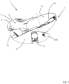
- FIGS 1-11 show different views of a first embodiment of the child vehicle seat 1 according to the invention.
- the child vehicle seat 1 comprises a base 2, a shell 3 fixed to the base 2 and a seat 4 located inside the shell 3.
- the seat 4 comprises a seating portion 5 and a backrest portion 6.
- the backrest portion 6 is at a side remote of the seating portion 5 provided with an operating mechanism 7.
- the backrest portion 6 is pivotable about a pivot axis A-A' with respect to the base 2.
- the seating portion 5 and the backrest portion 6 are pivotable with respect to each other about a pivot axis B.
- the seating portion 5 is at at a side remote of the backrest portion 6 provided with two pens 8 extending perpendicular to a main axis 9 of the child vehicle seat 1.
- the pens 8 of the seating portion 5 are slidably located in slots 10 of the shell 3.
- the slots 10 define the extreme positions of the sitting position and laying down position of the seating portion 5.
- the base 2 is on both longitudinal sides provided with a comb-shaped element 11 comprising a number of teeth 12, whereby between two adjacent teeth 12 a locking position 13 is located.
- the comb-shaped element 11 comprises three locking position 13. If desired only two or more than three locking positions 13 can be provided.
- the comb-shaped element 11 is plate-shaped, whereby the plate extends in the direction of the main axis 9 as well as substantially in vertical direction. In this manner the teeth are substantially directed to the front side of child vehicle seat 1.
- the backrest portion 6 is on both longitudinal sides provided with a locking element 14.
- the locking element 14 is pivotable about a pivot axis 15 extending parallel to the comb-shaped element 11.
- a first part 16 of the locking element 14 is provided with a hook 16'.
- the hook 16' prevents the locking element 14 to disengage from the comb-shaped element 11 by side impact in a crash and prevents the locking element to disengage in case of torsion that can happen in a crash (like with the infant seat is installed with a vehicle belt).
- This first part 16 is movable in and out of the locking positions 13.
- a second part 17 of the locking element 14 is located on the opposite side of the pivot axis 15.
- a pulling element 18 is connected to this second part 17.
- the pulling element 18 comprises a cable, a steel wire, an iron wire, a plastic wire, a rope or a webbing strap.
- a spring 19 is connected to the second part 17 pulling the second part 17 to the front side of the child vehicle seat 1 thereby pivoting the locking element 14 in a direction opposite to the directions indicated by arrows P1, P2 and pushing the first parts 16 into locking positions 13.
- the pivot axes 15 of both locking elements 14 are located between the two comb-shaped elements 11. It is also possible to locate them both outside of the comb-shaped elements 11 or to locate one between the comb-shaped elements 11 and one outside the comb-shaped elements 11.
- the operating mechanism 7 can best be seen in the figures 7A and 7B .
- the operating element 7 comprises a handle 20 being rotatable against spring force of springs 19 about a rotation axis 21 extending horizontally and perpendicular to a main axis 9 of the child vehicle seat 1.
- the operating element 7 also comprises two levers 22, each lever 22 being pivotable about a pivot axis 23 extending perpendicular to the rotation axis 21.
- the handle 20 is provided near two opposite ends with cams 24. Each cam 24 cooperates with a first end 25 of one of the levers 22.
- a second end 26 of each lever 22 is connected to the pulling element 18.
- the pivot axis 23 of the lever 22 is located between the first end 25 and second end 26 of lever 22.
- the child vehicle seat 1 can be moved from for example the first sitting position as shown in figure 10 to a second sitting position as shown in figure 11 in the following manner.
- the first parts 16 of the locking elements 14 are located in the most upper locking positions 11 of the comb-shaped elements 11.
- the user pivots the handle 20 in a direction as indicated by arrow P3.
- the cams 35 will be moved along the first ends 25 of the levers 22 and will force the levers 22 to rotated in the directions as indicated by arrows P4, P5, thereby pulling the pulling elements 18 in the direction as indicated by arrow P6.
- Displacement of the pulling elements 18 in the direction as indicated by arrow P6, will result in pivoting of the locking elements 14 in the directions as indicated by arrows P1, P2, whereby the locking elements 14 will be moved to an unlocked position ( figures 8B , 9B ).
- FIGS 12A and 12B show a second embodiment of an operating element 27 of a child vehicle seat 1 according to the invention.
- the operating element 27 comprises a handle 30 being movable against spring force of the springs 19 in a direction indicated by arrow P8 extending parallel to a main axis 9 of the child vehicle seat 1.
- the operating element 27 also comprises two levers 31, each lever 31 being pivotable about a pivot axis 32 extending parallel to a main axis 9 of the child vehicle seat 1.
- the handle 30 is near two opposite ends provided with springs 33 resting with one end to the handle 30 and with an opposite second end to a shell (not shown) of the child vehicle seat 1.
- Each first end 34 is provided with a cam 35 cooperating with the handle 30.
- a second end 36 of each lever 31 is connected to the pulling element 18.
- the pivot axis 32 of the lever 31 is located between the first end 34 and second end 36 of the lever 31.
- the first parts 16 of the locking elements 14 are located in the most upper locking positions 11 of the comb-shaped elements 11.
- the user pushes the handle 30 against spring force of the springs 33 in the direction as indicated by arrow P8.
- the handle 30 is pushed against the cams 35, and will force the cams 35 to move in a direction indicated by arrow P9, thereby forcing the levers 31 to rotated in the directions as indicated by arrows P10, P11.
- the pulling elements 18 will be pulled in the direction as indicated by arrow P6.
- the springs 18 can push the handle 30 in the locked position, in which case the springs 33 can be left behind.
- the teeth are substantially directed to the rear side of child vehicle seat 1.
- the locking element is located on the side of the teeth to be able to cooperate with the teeth.
- cams 24 are provided on the handle 20.
- the cams also can be provided on the first end 25 of lever 22 solely or both handle 20 and lever 22 are provided with cams respectively, so that the component force asserted on the lever is maximized and the contact areas of the handle 20 and lever 25 are optimized.
- the handle 30 can also be movable in vertical direction. In such a case the cams 35 need to be different to transfer the movement from the handle 30 to the locking element 14.
Landscapes
- Engineering & Computer Science (AREA)
- Aviation & Aerospace Engineering (AREA)
- Transportation (AREA)
- Mechanical Engineering (AREA)
- Health & Medical Sciences (AREA)
- Child & Adolescent Psychology (AREA)
- General Health & Medical Sciences (AREA)
- Seats For Vehicles (AREA)
- Chairs For Special Purposes, Such As Reclining Chairs (AREA)
Abstract

Description
- The invention relates to a child vehicle seat comprising at least a base, a seat comprising a seating portion and a backrest portion and an operating mechanism located at the backrest portion at a side remote of the seating portion, wherein the seating portion and the backrest portion are pivotable with respect to each other as well as movable with respect to the base, which base comprises a number of locking positions in which the backrest portion can be locked with respect to the base, whereby a locking element is movable by means of the operating mechanism from at least a first of said locking positions via an unlocked position to at least a second of said locking positions, whereby the backrest portion as well as the seating portion are being moved from a first sitting position to a second sitting position.
- The different sitting positions of the child vehicle seat provide the possibility to adapt the sitting position to the need of the child. Although it is called sitting position, the sitting position can also be more a reclined sleeping position.
- By a child vehicle seat known from
EP1225087A1 , the locking element comprises an engaging pin being translatable in the longitudinal direction of the pin from a position located inside an engaging hole as well as a through hole to a position outside of the holes. The engaging pin is being translated by pulling on a stiff wire. A disadvantage is that the stiff wire must be moved over the same distance as the pin. Another disadvantage is that the pin and the stiff wire must be moved in the same direction. This reduced the freedom of design of the child vehicle seat. - By a second embodiment of
EP1225087A1 , the locking element comprises a lock lever being pivotable about a pivot shaft extending horizontally and perpendicular to the main axis of the child vehicle seat. The main axis corresponds to the driving direction of the car in which the child vehicle seat will be used. The lock lever is provided with a lock plate receivable in any of a plurality of locating engaging holes. The lock lever is being manually operated by pulling it against spring force against an angle control plate located on the rear of the backrest portion. This has the disadvantage that the lock lever is out of reach when the child vehicle seat in use is located with the backrest portion against the backrest of the vehicle seat. The recline function is often used in rear facing driving direction. With the child seat in the rear facing driving direction the lever can be out of reach when the child seat is located on or close to the upper part of the backrest of the front driver or passenger seat. - At least one of the objects of the invention is to provide a child vehicle seat whereby a larger freedom of design is obtained regarding the movement of the locking element.
- This object is accomplished with the child vehicle seat according to the invention in that the locking element is pivotable about a pivot axis against spring force by means of a pulling element extending between the operating element and the locking element from the locking positions to the unlocked position, which pivot axis extends at least partially in vertical direction.
- By pivoting the locking element, the distance over which the locking element is being moved from a position inside a locking position to the unlocked position and the distance over which the operating element and the pulling element connected thereto must be moved will depend on the distance between the locking positions and the pivot axis as well as the distance between the connection of the pulling element to the locking element and the pivot axis. By amending these distances, a required ratio between the displacement of the locking element with respect to the locking position and the displacement of the operating element can be obtained. The part of the locking element cooperating with the locking positions can be located at an opposite side of the pivot axis as the connection of the pulling element to the locking element or at the same side. In case that the part of the locking element cooperating with the locking positions is located at the opposite side of the pivot axis as the connection of the pulling element to the locking element, movement of the pulling element in one direction will result in movement of the part of the locking element in opposite direction.
- During a crash the rotation axis is perpendicular to the crash direction, so unlocking due to inertia of locking elements is unlikely to happen.
- Since the pivot axis extends at least partially in vertical direction instead of horizontal axis by the second embodiment of
EP1225087A1 again a larger design of freedom regarding the movement of the locking element is obtained. - An embodiment of the child vehicle seat according to the invention is characterized in that the base is provided with a comb-shaped element comprising a number of teeth, whereby each locking position is located between two adjacent teeth.
- Such a comb-shaped element can easily be manufactured with a relatively small thickness so that it requires little space. The locking positions are automatically obtained and are located between two adjacent teeth.
- Such a comb-shaped element can be positioned in the sides of the child vehicle seat, leaving more space for the child, especially because internal dimensions and external dimensions of the child vehicle seat are regulated in the R129 car seat regulation of the EU.
- The teeth can have different shapes, like having a chamfer in one or more positions, offering the possibility to move from one seating position to another seating position without operating the recline handle. This could be convenient for the user to move the backrest from a more reclined seating position to a less reclined seating position.
- The teeth can have different shapes, like having a chamfer in one or more positions, offering the possibility to move from a reclined seating position to a more upright seating position. This can have advantages in case of a crash, where a more upright position results in lower injury risk for the child.
- Another embodiment of the child vehicle seat according to the invention is characterized in that the teeth are substantially directed to the front side or the rear side of child vehicle seat.
- In this manner, the preferable relatively thin comb-shaped element will extend in the main direction of the child vehicle seat. The orientation of the teeth has the advantage that the locking element is located on the front side or rear side of the comb-shaped element. In case of an accident the locking element will be pushed inside the locking position between two adjacent teeth so that a firm connection between the locking element and the comb-shaped element will be maintained.
- Another embodiment of the child vehicle seat according to the invention is characterized in that the pulling element comprises a cable, a steel wire, an iron wire, a plastic wire, a rope or a webbing strap.
- Such a pulling element can easily be manufactured, is relatively cheap and can be guided, if necessary, along any desired path in the child vehicle seat.
- The weight of such pulling element is relatively low, so the inertia of such pulling element will not lead to undesired unlocking of the connection.
- The weight of the child vehicle seat will be low which is convenient for the user because this is an infant carrier, and there are restrictions in product weight in the R129 regulation of the EU.
- Another embodiment of the child vehicle seat according to the invention is characterized in that on each side the child seat is provided with the same locking positions and locking element.
- By having locking positions as well as locking elements on both sides an even firmer connection between the backrest portion and the base is obtained.
- Another embodiment of the child vehicle seat according to the invention is characterized in that the operating element comprises a handle being rotatable against spring force about a rotation axis extending horizontally and perpendicular to a main axis of the child vehicle seat, which operating element also comprises two levers, each lever being pivotable about a pivot axis extending perpendicular to the rotation axis, whereby near two opposite ends the handle is provided with cams, each cam cooperates with a first end of one of the levers, whereby a second end of each lever is connected to the pulling element, whilst the pivot axis of the lever is located between the first and second end of lever.
- With such an operating element a user needs simply to pivot the handle to operate both levers. The cams will force the first ends of the levers to move, thereby pivoting the levers. When the levers are being pivoted, the second ends of the levers will also be moved, resulting in a movement of the pulling elements connected thereto. After releasing the handle, the handle and the levers will move back under spring force to the initial positions. The spring force can be relatively high to secure the locking element to lock into the comb-shaped element. Due to the position and geometry of the levers, the operating forces for the user can be relatively low. Cams are preferred to maximize the component force asserted on the lever and optimize the contact areas of the handle and lever. The cams can be solely provided on the handle or on the first ends of levers, or can be provided on both handle and the first ends of levers.
- Another embodiment of the child vehicle seat according to the invention is characterized in that the operating element comprises a handle being movable against spring force in a direction parallel to a main axis of the child vehicle seat, which operating element also comprises two levers, each lever being pivotable about a pivot axis, whereby two opposite ends of the handle cooperate with first ends of the levers, which first end is provided with a cam, whereby a second end of each lever is connected to the pulling element, whilst the pivot axis of the lever is located between the first and second end of lever.
- With such an operating element a user needs simply to push the handle to operate both levers. When the levers are being pivoted, the second ends of the levers will also be moved, resulting in a movement of the pulling elements connected thereto. After releasing the handle the handle and the levers will move back under spring force to the initial positions.
- The stroke of the operating element can be relatively small, due to the position and shape of the cams.
- The child vehicle seat according to the invention will further be explained with reference to the drawings, wherein,
-
figure 1 is a perspective view of a child vehicle seat according to the invention, -
figure 2 is a exploded view of the child vehicle seat as shown infigure 1 , -
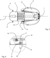
figure 3 is a top view of a part of the child vehicle seat as shown infigure 1 , which part comprises the seating portion and the backrest portion, -
figure 4 is a perspective view of a first embodiment of the operating element, the pulling elements, the locking elements as well as the locking positions of the child vehicle seat as shown infigure 1 , -
figure 5 is a perspective view of detail V of the child vehicle seat as shown infigure 2 , -
figure 6 is a perspective view of detail VI of the child vehicle seat as shown infigure 6 , -
figures 7A and 7B are enlarged perspective views of detail VII as shown infigure 1 , in the locked and unlocked position respectively, -
figures 8A and 8B are enlarged perspective views of detail VIII as shown infigure 1 , in the locked and unlocked position respectively, -
figures 9A and 9B are enlarged perspective views of detail IX as shown infigure 1 , in the locked and unlocked position respectively, -
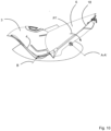
figure 10 is a cross section of a child vehicle seat as shown infigure 1 in a first sitting position, -
figure 11 is a cross section of a child vehicle seat as shown infigure 1 in a second sitting position, -
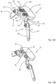
figure 12A and 12B figures 7A and 7B are enlarged perspective views of detail VII as shown infigure 1 of a second embodiment of the operating element, in the locked and unlocked position respectively. - In the drawings, like reference numerals refer to like elements.
-
Figures 1-11 show different views of a first embodiment of thechild vehicle seat 1 according to the invention. Thechild vehicle seat 1 comprises abase 2, ashell 3 fixed to thebase 2 and aseat 4 located inside theshell 3. Theseat 4 comprises aseating portion 5 and abackrest portion 6. Thebackrest portion 6 is at a side remote of theseating portion 5 provided with anoperating mechanism 7. Thebackrest portion 6 is pivotable about a pivot axis A-A' with respect to thebase 2. Theseating portion 5 and thebackrest portion 6 are pivotable with respect to each other about a pivot axis B. Theseating portion 5 is at at a side remote of thebackrest portion 6 provided with twopens 8 extending perpendicular to amain axis 9 of thechild vehicle seat 1. Thepens 8 of theseating portion 5 are slidably located inslots 10 of theshell 3. Theslots 10 define the extreme positions of the sitting position and laying down position of theseating portion 5. Thebase 2 is on both longitudinal sides provided with a comb-shapedelement 11 comprising a number ofteeth 12, whereby between two adjacent teeth 12 alocking position 13 is located. In the present embodiment the comb-shapedelement 11 comprises three lockingposition 13. If desired only two or more than three lockingpositions 13 can be provided. The comb-shapedelement 11 is plate-shaped, whereby the plate extends in the direction of themain axis 9 as well as substantially in vertical direction. In this manner the teeth are substantially directed to the front side ofchild vehicle seat 1. - The
backrest portion 6 is on both longitudinal sides provided with a lockingelement 14. The lockingelement 14 is pivotable about apivot axis 15 extending parallel to the comb-shapedelement 11. Afirst part 16 of the lockingelement 14 is provided with a hook 16'. The hook 16' prevents the lockingelement 14 to disengage from the comb-shapedelement 11 by side impact in a crash and prevents the locking element to disengage in case of torsion that can happen in a crash (like with the infant seat is installed with a vehicle belt). Thisfirst part 16 is movable in and out of the locking positions 13. Asecond part 17 of the lockingelement 14 is located on the opposite side of thepivot axis 15. A pullingelement 18 is connected to thissecond part 17. The pullingelement 18 comprises a cable, a steel wire, an iron wire, a plastic wire, a rope or a webbing strap. - Also, a
spring 19 is connected to thesecond part 17 pulling thesecond part 17 to the front side of thechild vehicle seat 1 thereby pivoting the lockingelement 14 in a direction opposite to the directions indicated by arrows P1, P2 and pushing thefirst parts 16 into locking positions 13. By this embodiment the pivot axes 15 of both lockingelements 14 are located between the two comb-shapedelements 11. It is also possible to locate them both outside of the comb-shapedelements 11 or to locate one between the comb-shapedelements 11 and one outside the comb-shapedelements 11. - The
operating mechanism 7 can best be seen in thefigures 7A and 7B . Theoperating element 7 comprises ahandle 20 being rotatable against spring force ofsprings 19 about arotation axis 21 extending horizontally and perpendicular to amain axis 9 of thechild vehicle seat 1. Theoperating element 7 also comprises twolevers 22, eachlever 22 being pivotable about apivot axis 23 extending perpendicular to therotation axis 21. Thehandle 20 is provided near two opposite ends withcams 24. Eachcam 24 cooperates with afirst end 25 of one of thelevers 22. Asecond end 26 of eachlever 22 is connected to the pullingelement 18. Thepivot axis 23 of thelever 22 is located between thefirst end 25 andsecond end 26 oflever 22. - The
child vehicle seat 1 can be moved from for example the first sitting position as shown infigure 10 to a second sitting position as shown infigure 11 in the following manner. - In the first sitting position as shown in
figure 10 , thefirst parts 16 of the lockingelements 14 are located in the most upper locking positions 11 of the comb-shapedelements 11. When a user wants to change to the second sitting position, the user pivots thehandle 20 in a direction as indicated by arrow P3. Thecams 35 will be moved along the first ends 25 of thelevers 22 and will force thelevers 22 to rotated in the directions as indicated by arrows P4, P5, thereby pulling the pullingelements 18 in the direction as indicated by arrow P6. Displacement of the pullingelements 18 in the direction as indicated by arrow P6, will result in pivoting of the lockingelements 14 in the directions as indicated by arrows P1, P2, whereby the lockingelements 14 will be moved to an unlocked position (figures 8B ,9B ). The user can now pivot thebackrest portion 6 about pivot axis A-A1, thereby forcing theseating portion 5 to pivot about pivot axis B and to slide with thepens 8 throughslots 10 until the second sitting position has been reached. When releasing thehandle 20, the lockingelements 14 will be forced bysprings 19 into another lockingposition 13. -
Figures 12A and 12B show a second embodiment of anoperating element 27 of achild vehicle seat 1 according to the invention. The operatingelement 27 comprises ahandle 30 being movable against spring force of thesprings 19 in a direction indicated by arrow P8 extending parallel to amain axis 9 of thechild vehicle seat 1. The operatingelement 27 also comprises twolevers 31, eachlever 31 being pivotable about apivot axis 32 extending parallel to amain axis 9 of thechild vehicle seat 1. Thehandle 30 is near two opposite ends provided withsprings 33 resting with one end to thehandle 30 and with an opposite second end to a shell (not shown) of thechild vehicle seat 1. Eachfirst end 34 is provided with acam 35 cooperating with thehandle 30. Asecond end 36 of eachlever 31 is connected to the pullingelement 18. Thepivot axis 32 of thelever 31 is located between thefirst end 34 andsecond end 36 of thelever 31. - The
child vehicle seat 1 comprisingoperating element 27 can be moved from for example the first sitting position as shown infigure 10 to a second sitting position as shown infigure 11 in the following manner. - In the first sitting position as shown in
figure 10 , thefirst parts 16 of the lockingelements 14 are located in the most upper locking positions 11 of the comb-shapedelements 11. When a user wants to change to the second sitting position, the user pushes thehandle 30 against spring force of thesprings 33 in the direction as indicated by arrow P8. Thehandle 30 is pushed against thecams 35, and will force thecams 35 to move in a direction indicated by arrow P9, thereby forcing thelevers 31 to rotated in the directions as indicated by arrows P10, P11. By doing so, the pullingelements 18 will be pulled in the direction as indicated by arrow P6. Displacement of the pullingelements 18 in the direction as indicated by arrow P6, will result in pivoting of the lockingelements 14 in the directions as indicated by arrows P1, P2, whereby the lockingelements 14 will be moved to an unlocked position (figures 8B ,9B ). The user can now pivot thebackrest portion 6 about pivot axis A-A1, thereby forcing theseating portion 5 to pivot about pivot axis B and to slide with thepens 8 throughslots 10 until the second sitting position has been reached. When releasing thehandle 20, the lockingelements 14 will be forced bysprings 19 into another lockingposition 13. - It is also possible that the
springs 18 can push thehandle 30 in the locked position, in which case thesprings 33 can be left behind. - It is also possible that the teeth are substantially directed to the rear side of
child vehicle seat 1. The locking element is located on the side of the teeth to be able to cooperate with the teeth. - In the shown embodiment the
cams 24 are provided on thehandle 20. However, the cams also can be provided on thefirst end 25 oflever 22 solely or both handle 20 andlever 22 are provided with cams respectively, so that the component force asserted on the lever is maximized and the contact areas of thehandle 20 andlever 25 are optimized. - It has to be noted that the
handle element 18 and lockingelement 14 are interlinked as one mechanism. If one of these elements is moved by or against spring force, the other elements will be moved accordingly. Therefore, at least one of thehandles elements 14 is directly connected with a spring. The lockingelements 14 will be eventually restored at the initial position when releasing thehandle - The
handle 30 can also be movable in vertical direction. In such a case thecams 35 need to be different to transfer the movement from thehandle 30 to the lockingelement 14. -
- 1
- child vehicle seat
- 2
- base
- 3
- shell
- 4
- seat
- 5
- seating portion
- 6
- backrest portion
- 7
- operating mechanism
- 8
- pen
- 9
- main axis
- 10
- slot
- 11
- comb-shaped element
- 12
- teeth
- 13
- locking position
- 14
- locking element
- 15
- pivot axis
- 16'
- hook
- 16
- first part
- 17
- second part
- 18
- pulling element
- 19
- spring
- 20
- handle
- 21
- rotation axis
- 22
- lever
- 23
- pivot axis
- 24
- cam
- 25
- first end
- 26
- second end
- 27
- operating element
- 30
- handle
- 31
- lever
- 32
- pivot axis
- 33
- spring
- 34
- first end
- 35
- cam
- 36
- second end
- A-A1
- pivot axis
- B
- pivot axis
- P1
- arrow
- P2
- arrow
- P3
- arrow
- P4
- arrow
- P5
- arrow
- P6
- arrow
- P8
- arrow
- P9
- arrow
- P10
- arrow
- P11
- arrow
Claims (8)
- Child vehicle seat (1) comprising at least a base (2), a seat comprising a seating portion (5) and a backrest portion (6) and an operating mechanism (7) located at the backrest portion (6) at a side remote of the seating portion (5), wherein the seating portion (5) and the backrest portion (6) are pivotable with respect to each other as well as movable with respect to the base (2), which base (2) comprises a number of locking positions (13) in which the backrest portion (6) can be locked with respect to the base (2), whereby a locking element (14) is movable by means of the operating mechanism (7) from at least a first of said locking positions (13) via an unlocked position to at least a second of said locking positions (13), whereby the backrest portion (6) as well as the seating portion (5) are being moved from a first sitting position to a second sitting position, characterized in that the locking element (14) is pivotable about a pivot axis (15) against spring (19, 33) force by means of a pulling element (18) extending between the operating element (27) and the locking element (14) from the locking positions (13) to the unlocked position, which pivot axis (15) extends at least partially in vertical direction.
- Child vehicle seat (1) according to claim 1, characterized in that the base (2) is provided with a comb-shaped element (11) comprising a number of teeth (12), whereby each locking position (13) is located between two adjacent teeth.
- Child vehicle seat (1) according to claim 2, characterized in that the teeth (12) are substantially directed to the front side or the rear side of child vehicle seat (i).
- Child vehicle seat (1) according to claim 1, 2 or 3, characterized in that the pulling element (18) comprises a cable, a steel wire, an iron wire, a plastic wire, a rope or a webbing strap.
- Child vehicle seat (1) according to one of the preceding claims, characterized in that on each side the child seat is provided with the same locking positions (13) and locking element (14).
- Child vehicle seat (1) according to claim 5, characterized in that the operating element comprises a handle (20) being rotatable against spring force about a rotation axis (21) extending horizontally and perpendicular to a main axis (9) of the child vehicle seat, which operating element (27) also comprises two levers (22), each lever (22) being pivotable about a pivot axis (23) extending perpendicular to the rotation axis (21), whereby near two opposite ends the handle (20) cooperates with a first end (25) of one of the levers (22), whereby a second end (26) of each lever (22) is connected to the pulling element (18), whilst the pivot axis (23) of the lever (22) is located between the first and second end (26) of lever (22).
- Child vehicle seat (1) according to claim 6, characterized in that the two opposite ends the handle (20) and / or the first ends (25) of levers (22) are provided with cams (24).
- Child vehicle seat (1) according to claim 5, characterized in that the operating element (27) comprises a handle (30) being movable against spring force in a direction parallel to a main axis (9) of the child vehicle seat, which operating element (27) also comprises two levers (31), each lever (31) being pivotable about a pivot axis (32), whereby two opposite ends of the handle (30) cooperate with first ends (34) of the levers (31), which first end (34) is provided with a cam (35) , whereby a second end (36) of each lever (31) is connected to the pulling element (18), whilst the pivot axis (32) of the lever (31) is located between the first and second end (36) of lever (31).
Priority Applications (5)
| Application Number | Priority Date | Filing Date | Title |
|---|---|---|---|
| EP23167971.3A EP4446163B1 (en) | 2023-04-14 | 2023-04-14 | Child vehicle seat |
| ES23167971T ES3044438T3 (en) | 2023-04-14 | 2023-04-14 | Child vehicle seat |
| DE202023102077.1U DE202023102077U1 (en) | 2023-04-14 | 2023-04-20 | car seat |
| CN202410438719.7A CN118288865A (en) | 2023-04-14 | 2024-04-12 | Child's appliance |
| CN202420753468.7U CN222372733U (en) | 2023-04-14 | 2024-04-12 | Child's appliance |
Applications Claiming Priority (1)
| Application Number | Priority Date | Filing Date | Title |
|---|---|---|---|
| EP23167971.3A EP4446163B1 (en) | 2023-04-14 | 2023-04-14 | Child vehicle seat |
Publications (2)
| Publication Number | Publication Date |
|---|---|
| EP4446163A1 true EP4446163A1 (en) | 2024-10-16 |
| EP4446163B1 EP4446163B1 (en) | 2025-07-30 |
Family
ID=86052026
Family Applications (1)
| Application Number | Title | Priority Date | Filing Date |
|---|---|---|---|
| EP23167971.3A Active EP4446163B1 (en) | 2023-04-14 | 2023-04-14 | Child vehicle seat |
Country Status (4)
| Country | Link |
|---|---|
| EP (1) | EP4446163B1 (en) |
| CN (2) | CN118288865A (en) |
| DE (1) | DE202023102077U1 (en) |
| ES (1) | ES3044438T3 (en) |
Citations (3)
| Publication number | Priority date | Publication date | Assignee | Title |
|---|---|---|---|---|
| EP0640508A1 (en) * | 1993-08-26 | 1995-03-01 | Hts As | Children's seat for vehicles |
| EP1225087A1 (en) | 1999-10-27 | 2002-07-24 | Aprica Kassai Kabushikikaisha | Baby care device |
| US20120013160A1 (en) * | 2010-07-15 | 2012-01-19 | Williams Bruce L | Child Safety Seat Assembly |
-
2023
- 2023-04-14 EP EP23167971.3A patent/EP4446163B1/en active Active
- 2023-04-14 ES ES23167971T patent/ES3044438T3/en active Active
- 2023-04-20 DE DE202023102077.1U patent/DE202023102077U1/en active Active
-
2024
- 2024-04-12 CN CN202410438719.7A patent/CN118288865A/en active Pending
- 2024-04-12 CN CN202420753468.7U patent/CN222372733U/en active Active
Patent Citations (3)
| Publication number | Priority date | Publication date | Assignee | Title |
|---|---|---|---|---|
| EP0640508A1 (en) * | 1993-08-26 | 1995-03-01 | Hts As | Children's seat for vehicles |
| EP1225087A1 (en) | 1999-10-27 | 2002-07-24 | Aprica Kassai Kabushikikaisha | Baby care device |
| US20120013160A1 (en) * | 2010-07-15 | 2012-01-19 | Williams Bruce L | Child Safety Seat Assembly |
Also Published As
| Publication number | Publication date |
|---|---|
| EP4446163B1 (en) | 2025-07-30 |
| ES3044438T3 (en) | 2025-11-26 |
| DE202023102077U1 (en) | 2023-07-21 |
| CN118288865A (en) | 2024-07-05 |
| CN222372733U (en) | 2025-01-21 |
Similar Documents
| Publication | Publication Date | Title |
|---|---|---|
| EP4438403B1 (en) | Child safety seat | |
| US7686397B2 (en) | Easy entry seat track release mechanism | |
| EP2020335B1 (en) | Lock apparatus of seat for vehicle | |
| KR101015986B1 (en) | Sheet | |
| US6149235A (en) | Rotary-cam type reclining device | |
| KR100442762B1 (en) | A vehicle seat provided with a f0ld-down back | |
| US20250026250A1 (en) | Child restraint carrier and locking mechanism thereof | |
| EP4212389B1 (en) | Child safety seat | |
| JP2002282091A (en) | Seat device with foldable backrest | |
| US10150393B2 (en) | Fitting with a pivoting-forwards mechanism and easy-entry latch, and vehicle seat with such a fitting | |
| US10081271B2 (en) | Vehicle slide rail device | |
| EP4446163B1 (en) | Child vehicle seat | |
| JP5518293B2 (en) | Seat sliding device for vehicle seat and storage seat for vehicle | |
| JP5356696B2 (en) | Seat sliding device for vehicle seat and storage seat for vehicle | |
| CN111688550B (en) | Vehicle seat | |
| JP5574571B2 (en) | Vehicle storage seat | |
| KR102801152B1 (en) | Vehicle seatback locking device and folding seat equipped with the device | |
| US20070262620A1 (en) | Seat Articulating Device | |
| JP5356693B2 (en) | Vehicle storage seat | |
| JP5227608B2 (en) | Vehicle seat urging device and manufacturing method thereof | |
| JP5356694B2 (en) | Seat slide device for retractable seat for vehicle | |
| US20250121744A1 (en) | Walk-in device for vehicle seat | |
| JP5356695B2 (en) | Vehicle storage seat | |
| JP4795809B2 (en) | Seat reclining device |
Legal Events
| Date | Code | Title | Description |
|---|---|---|---|
| PUAI | Public reference made under article 153(3) epc to a published international application that has entered the european phase |
Free format text: ORIGINAL CODE: 0009012 |
|
| STAA | Information on the status of an ep patent application or granted ep patent |
Free format text: STATUS: REQUEST FOR EXAMINATION WAS MADE |
|
| 17P | Request for examination filed |
Effective date: 20240214 |
|
| AK | Designated contracting states |
Kind code of ref document: A1 Designated state(s): AL AT BE BG CH CY CZ DE DK EE ES FI FR GB GR HR HU IE IS IT LI LT LU LV MC ME MK MT NL NO PL PT RO RS SE SI SK SM TR |
|
| GRAP | Despatch of communication of intention to grant a patent |
Free format text: ORIGINAL CODE: EPIDOSNIGR1 |
|
| STAA | Information on the status of an ep patent application or granted ep patent |
Free format text: STATUS: GRANT OF PATENT IS INTENDED |
|
| INTG | Intention to grant announced |
Effective date: 20241115 |
|
| P01 | Opt-out of the competence of the unified patent court (upc) registered |
Free format text: CASE NUMBER: APP_67462/2024 Effective date: 20241220 |
|
| GRAJ | Information related to disapproval of communication of intention to grant by the applicant or resumption of examination proceedings by the epo deleted |
Free format text: ORIGINAL CODE: EPIDOSDIGR1 |
|
| STAA | Information on the status of an ep patent application or granted ep patent |
Free format text: STATUS: REQUEST FOR EXAMINATION WAS MADE |
|
| GRAP | Despatch of communication of intention to grant a patent |
Free format text: ORIGINAL CODE: EPIDOSNIGR1 |
|
| STAA | Information on the status of an ep patent application or granted ep patent |
Free format text: STATUS: GRANT OF PATENT IS INTENDED |
|
| INTC | Intention to grant announced (deleted) | ||
| INTG | Intention to grant announced |
Effective date: 20250303 |
|
| GRAS | Grant fee paid |
Free format text: ORIGINAL CODE: EPIDOSNIGR3 |
|
| GRAA | (expected) grant |
Free format text: ORIGINAL CODE: 0009210 |
|
| STAA | Information on the status of an ep patent application or granted ep patent |
Free format text: STATUS: THE PATENT HAS BEEN GRANTED |
|
| AK | Designated contracting states |
Kind code of ref document: B1 Designated state(s): AL AT BE BG CH CY CZ DE DK EE ES FI FR GB GR HR HU IE IS IT LI LT LU LV MC ME MK MT NL NO PL PT RO RS SE SI SK SM TR |
|
| REG | Reference to a national code |
Ref country code: GB Ref legal event code: FG4D |
|
| REG | Reference to a national code |
Ref country code: CH Ref legal event code: EP |
|
| REG | Reference to a national code |
Ref country code: NL Ref legal event code: FP |
|
| REG | Reference to a national code |
Ref country code: DE Ref legal event code: R096 Ref document number: 602023005123 Country of ref document: DE |
|
| REG | Reference to a national code |
Ref country code: IE Ref legal event code: FG4D |
|
| REG | Reference to a national code |
Ref country code: ES Ref legal event code: FG2A Ref document number: 3044438 Country of ref document: ES Kind code of ref document: T3 Effective date: 20251126 |
|
| REG | Reference to a national code |
Ref country code: AT Ref legal event code: MK05 Ref document number: 1818600 Country of ref document: AT Kind code of ref document: T Effective date: 20250730 |
|
| PG25 | Lapsed in a contracting state [announced via postgrant information from national office to epo] |
Ref country code: PT Free format text: LAPSE BECAUSE OF FAILURE TO SUBMIT A TRANSLATION OF THE DESCRIPTION OR TO PAY THE FEE WITHIN THE PRESCRIBED TIME-LIMIT Effective date: 20251202 |
|
| PG25 | Lapsed in a contracting state [announced via postgrant information from national office to epo] |
Ref country code: IS Free format text: LAPSE BECAUSE OF FAILURE TO SUBMIT A TRANSLATION OF THE DESCRIPTION OR TO PAY THE FEE WITHIN THE PRESCRIBED TIME-LIMIT Effective date: 20251130 |
|
| PG25 | Lapsed in a contracting state [announced via postgrant information from national office to epo] |
Ref country code: NO Free format text: LAPSE BECAUSE OF FAILURE TO SUBMIT A TRANSLATION OF THE DESCRIPTION OR TO PAY THE FEE WITHIN THE PRESCRIBED TIME-LIMIT Effective date: 20251030 |
|
| REG | Reference to a national code |
Ref country code: LT Ref legal event code: MG9D |
|
| PG25 | Lapsed in a contracting state [announced via postgrant information from national office to epo] |
Ref country code: AT Free format text: LAPSE BECAUSE OF FAILURE TO SUBMIT A TRANSLATION OF THE DESCRIPTION OR TO PAY THE FEE WITHIN THE PRESCRIBED TIME-LIMIT Effective date: 20250730 |
|
| PG25 | Lapsed in a contracting state [announced via postgrant information from national office to epo] |
Ref country code: FI Free format text: LAPSE BECAUSE OF FAILURE TO SUBMIT A TRANSLATION OF THE DESCRIPTION OR TO PAY THE FEE WITHIN THE PRESCRIBED TIME-LIMIT Effective date: 20250730 |
|
| PG25 | Lapsed in a contracting state [announced via postgrant information from national office to epo] |
Ref country code: HR Free format text: LAPSE BECAUSE OF FAILURE TO SUBMIT A TRANSLATION OF THE DESCRIPTION OR TO PAY THE FEE WITHIN THE PRESCRIBED TIME-LIMIT Effective date: 20250730 |
|
| PG25 | Lapsed in a contracting state [announced via postgrant information from national office to epo] |
Ref country code: GR Free format text: LAPSE BECAUSE OF FAILURE TO SUBMIT A TRANSLATION OF THE DESCRIPTION OR TO PAY THE FEE WITHIN THE PRESCRIBED TIME-LIMIT Effective date: 20251031 |
|
| PG25 | Lapsed in a contracting state [announced via postgrant information from national office to epo] |
Ref country code: SE Free format text: LAPSE BECAUSE OF FAILURE TO SUBMIT A TRANSLATION OF THE DESCRIPTION OR TO PAY THE FEE WITHIN THE PRESCRIBED TIME-LIMIT Effective date: 20250730 |
|
| PG25 | Lapsed in a contracting state [announced via postgrant information from national office to epo] |
Ref country code: LV Free format text: LAPSE BECAUSE OF FAILURE TO SUBMIT A TRANSLATION OF THE DESCRIPTION OR TO PAY THE FEE WITHIN THE PRESCRIBED TIME-LIMIT Effective date: 20250730 |
|
| PG25 | Lapsed in a contracting state [announced via postgrant information from national office to epo] |
Ref country code: BG Free format text: LAPSE BECAUSE OF FAILURE TO SUBMIT A TRANSLATION OF THE DESCRIPTION OR TO PAY THE FEE WITHIN THE PRESCRIBED TIME-LIMIT Effective date: 20250730 Ref country code: PL Free format text: LAPSE BECAUSE OF FAILURE TO SUBMIT A TRANSLATION OF THE DESCRIPTION OR TO PAY THE FEE WITHIN THE PRESCRIBED TIME-LIMIT Effective date: 20250730 |
|
| PG25 | Lapsed in a contracting state [announced via postgrant information from national office to epo] |
Ref country code: RS Free format text: LAPSE BECAUSE OF FAILURE TO SUBMIT A TRANSLATION OF THE DESCRIPTION OR TO PAY THE FEE WITHIN THE PRESCRIBED TIME-LIMIT Effective date: 20251030 |
|
| PG25 | Lapsed in a contracting state [announced via postgrant information from national office to epo] |
Ref country code: SM Free format text: LAPSE BECAUSE OF FAILURE TO SUBMIT A TRANSLATION OF THE DESCRIPTION OR TO PAY THE FEE WITHIN THE PRESCRIBED TIME-LIMIT Effective date: 20250730 |
|
| PG25 | Lapsed in a contracting state [announced via postgrant information from national office to epo] |
Ref country code: DK Free format text: LAPSE BECAUSE OF FAILURE TO SUBMIT A TRANSLATION OF THE DESCRIPTION OR TO PAY THE FEE WITHIN THE PRESCRIBED TIME-LIMIT Effective date: 20250730 |
|
| PGFP | Annual fee paid to national office [announced via postgrant information from national office to epo] |
Ref country code: NL Payment date: 20260318 Year of fee payment: 4 |
|
| PG25 | Lapsed in a contracting state [announced via postgrant information from national office to epo] |
Ref country code: CZ Free format text: LAPSE BECAUSE OF FAILURE TO SUBMIT A TRANSLATION OF THE DESCRIPTION OR TO PAY THE FEE WITHIN THE PRESCRIBED TIME-LIMIT Effective date: 20250730 |
|
| PG25 | Lapsed in a contracting state [announced via postgrant information from national office to epo] |
Ref country code: EE Free format text: LAPSE BECAUSE OF FAILURE TO SUBMIT A TRANSLATION OF THE DESCRIPTION OR TO PAY THE FEE WITHIN THE PRESCRIBED TIME-LIMIT Effective date: 20250730 Ref country code: SK Free format text: LAPSE BECAUSE OF FAILURE TO SUBMIT A TRANSLATION OF THE DESCRIPTION OR TO PAY THE FEE WITHIN THE PRESCRIBED TIME-LIMIT Effective date: 20250730 |
|
| REG | Reference to a national code |
Ref country code: DE Ref legal event code: R097 Ref document number: 602023005123 Country of ref document: DE |
|
| PLBE | No opposition filed within time limit |
Free format text: ORIGINAL CODE: 0009261 |
|
| STAA | Information on the status of an ep patent application or granted ep patent |
Free format text: STATUS: NO OPPOSITION FILED WITHIN TIME LIMIT |
|
| REG | Reference to a national code |
Ref country code: CH Ref legal event code: L10 Free format text: ST27 STATUS EVENT CODE: U-0-0-L10-L00 (AS PROVIDED BY THE NATIONAL OFFICE) Effective date: 20260611 |
|
| PG25 | Lapsed in a contracting state [announced via postgrant information from national office to epo] |
Ref country code: LT Free format text: LAPSE BECAUSE OF FAILURE TO SUBMIT A TRANSLATION OF THE DESCRIPTION OR TO PAY THE FEE WITHIN THE PRESCRIBED TIME-LIMIT Effective date: 20250730 |
|
| 26N | No opposition filed |
Effective date: 20260501 |
|
| PGFP | Annual fee paid to national office [announced via postgrant information from national office to epo] |
Ref country code: ES Payment date: 20260617 Year of fee payment: 4 |
|
| PGFP | Annual fee paid to national office [announced via postgrant information from national office to epo] |
Ref country code: IT Payment date: 20260430 Year of fee payment: 4 |
|
| PGFP | Annual fee paid to national office [announced via postgrant information from national office to epo] |
Ref country code: DE Payment date: 20260422 Year of fee payment: 4 |
|
| PGFP | Annual fee paid to national office [announced via postgrant information from national office to epo] |
Ref country code: FR Payment date: 20260420 Year of fee payment: 4 |