EP4446160A1 - Vehicle and opening/closing structure of charging port thereof - Google Patents
Vehicle and opening/closing structure of charging port thereof Download PDFInfo
- Publication number
- EP4446160A1 EP4446160A1 EP21966823.3A EP21966823A EP4446160A1 EP 4446160 A1 EP4446160 A1 EP 4446160A1 EP 21966823 A EP21966823 A EP 21966823A EP 4446160 A1 EP4446160 A1 EP 4446160A1
- Authority
- EP
- European Patent Office
- Prior art keywords
- charging opening
- charging
- opening
- box
- cover
- Prior art date
- Legal status (The legal status is an assumption and is not a legal conclusion. Google has not performed a legal analysis and makes no representation as to the accuracy of the status listed.)
- Granted
Links
Images


Classifications
-
- B—PERFORMING OPERATIONS; TRANSPORTING
- B60—VEHICLES IN GENERAL
- B60L—PROPULSION OF ELECTRICALLY-PROPELLED VEHICLES; SUPPLYING ELECTRIC POWER FOR AUXILIARY EQUIPMENT OF ELECTRICALLY-PROPELLED VEHICLES; ELECTRODYNAMIC BRAKE SYSTEMS FOR VEHICLES IN GENERAL; MAGNETIC SUSPENSION OR LEVITATION FOR VEHICLES; MONITORING OPERATING VARIABLES OF ELECTRICALLY-PROPELLED VEHICLES; ELECTRIC SAFETY DEVICES FOR ELECTRICALLY-PROPELLED VEHICLES
- B60L53/00—Methods of charging batteries, specially adapted for electric vehicles; Charging stations or on-board charging equipment therefor; Exchange of energy storage elements in electric vehicles
- B60L53/10—Methods of charging batteries, specially adapted for electric vehicles; Charging stations or on-board charging equipment therefor; Exchange of energy storage elements in electric vehicles characterised by the energy transfer between the charging station and the vehicle
- B60L53/14—Conductive energy transfer
- B60L53/16—Connectors, e.g. plugs or sockets, specially adapted for charging electric vehicles
-
- B—PERFORMING OPERATIONS; TRANSPORTING
- B60—VEHICLES IN GENERAL
- B60K—ARRANGEMENT OR MOUNTING OF PROPULSION UNITS OR OF TRANSMISSIONS IN VEHICLES; ARRANGEMENT OR MOUNTING OF PLURAL DIVERSE PRIME-MOVERS IN VEHICLES; AUXILIARY DRIVES FOR VEHICLES; INSTRUMENTATION OR DASHBOARDS FOR VEHICLES; ARRANGEMENTS IN CONNECTION WITH COOLING, AIR INTAKE, GAS EXHAUST OR FUEL SUPPLY OF PROPULSION UNITS IN VEHICLES
- B60K15/00—Arrangement in connection with fuel supply of combustion engines or other fuel consuming energy converters, e.g. fuel cells; Mounting or construction of fuel tanks
- B60K15/03—Fuel tanks
- B60K15/04—Tank inlets
- B60K15/05—Inlet covers
-
- B—PERFORMING OPERATIONS; TRANSPORTING
- B62—LAND VEHICLES FOR TRAVELLING OTHERWISE THAN ON RAILS
- B62D—MOTOR VEHICLES; TRAILERS
- B62D25/00—Superstructure or monocoque structure sub-units; Parts or details thereof not otherwise provided for
- B62D25/24—Superstructure sub-units with access or drainage openings having movable or removable closures; Sealing means therefor
-
- B—PERFORMING OPERATIONS; TRANSPORTING
- B60—VEHICLES IN GENERAL
- B60K—ARRANGEMENT OR MOUNTING OF PROPULSION UNITS OR OF TRANSMISSIONS IN VEHICLES; ARRANGEMENT OR MOUNTING OF PLURAL DIVERSE PRIME-MOVERS IN VEHICLES; AUXILIARY DRIVES FOR VEHICLES; INSTRUMENTATION OR DASHBOARDS FOR VEHICLES; ARRANGEMENTS IN CONNECTION WITH COOLING, AIR INTAKE, GAS EXHAUST OR FUEL SUPPLY OF PROPULSION UNITS IN VEHICLES
- B60K15/00—Arrangement in connection with fuel supply of combustion engines or other fuel consuming energy converters, e.g. fuel cells; Mounting or construction of fuel tanks
- B60K15/03—Fuel tanks
- B60K15/04—Tank inlets
- B60K15/05—Inlet covers
- B60K2015/0515—Arrangements for closing or opening of inlet cover
- B60K2015/0538—Arrangements for closing or opening of inlet cover with open or close mechanism automatically actuated
-
- Y—GENERAL TAGGING OF NEW TECHNOLOGICAL DEVELOPMENTS; GENERAL TAGGING OF CROSS-SECTIONAL TECHNOLOGIES SPANNING OVER SEVERAL SECTIONS OF THE IPC; TECHNICAL SUBJECTS COVERED BY FORMER USPC CROSS-REFERENCE ART COLLECTIONS [XRACs] AND DIGESTS
- Y02—TECHNOLOGIES OR APPLICATIONS FOR MITIGATION OR ADAPTATION AGAINST CLIMATE CHANGE
- Y02T—CLIMATE CHANGE MITIGATION TECHNOLOGIES RELATED TO TRANSPORTATION
- Y02T10/00—Road transport of goods or passengers
- Y02T10/60—Other road transportation technologies with climate change mitigation effect
- Y02T10/70—Energy storage systems for electromobility, e.g. batteries
-
- Y—GENERAL TAGGING OF NEW TECHNOLOGICAL DEVELOPMENTS; GENERAL TAGGING OF CROSS-SECTIONAL TECHNOLOGIES SPANNING OVER SEVERAL SECTIONS OF THE IPC; TECHNICAL SUBJECTS COVERED BY FORMER USPC CROSS-REFERENCE ART COLLECTIONS [XRACs] AND DIGESTS
- Y02—TECHNOLOGIES OR APPLICATIONS FOR MITIGATION OR ADAPTATION AGAINST CLIMATE CHANGE
- Y02T—CLIMATE CHANGE MITIGATION TECHNOLOGIES RELATED TO TRANSPORTATION
- Y02T10/00—Road transport of goods or passengers
- Y02T10/60—Other road transportation technologies with climate change mitigation effect
- Y02T10/7072—Electromobility specific charging systems or methods for batteries, ultracapacitors, supercapacitors or double-layer capacitors
-
- Y—GENERAL TAGGING OF NEW TECHNOLOGICAL DEVELOPMENTS; GENERAL TAGGING OF CROSS-SECTIONAL TECHNOLOGIES SPANNING OVER SEVERAL SECTIONS OF THE IPC; TECHNICAL SUBJECTS COVERED BY FORMER USPC CROSS-REFERENCE ART COLLECTIONS [XRACs] AND DIGESTS
- Y02—TECHNOLOGIES OR APPLICATIONS FOR MITIGATION OR ADAPTATION AGAINST CLIMATE CHANGE
- Y02T—CLIMATE CHANGE MITIGATION TECHNOLOGIES RELATED TO TRANSPORTATION
- Y02T90/00—Enabling technologies or technologies with a potential or indirect contribution to GHG emissions mitigation
- Y02T90/10—Technologies relating to charging of electric vehicles
- Y02T90/14—Plug-in electric vehicles
Definitions
- the present invention relates to the field of vehicles and, in particular, to a vehicle and an opening/closing structure for a charging opening thereof.
- An object of a first aspect of the present invention is to provide an opening/closing structure for a charging opening of a vehicle, which can improve the user experience and reduce restrictions on modeling.
- a further object of the first aspect of the present invention is to improve the rigidity and stability of the entire opening/closing structure.
- An object of a second aspect of the present invention is to provide a vehicle.
- the present invention provides an opening/closing structure for a charging opening of a vehicle including:
- the opening/closing structure for the charging opening of the vehicle further includes:
- the rotation hinge is provided with a connecting post
- the driving device is a rotating motor with an output shaft that is reciprocatingly stretchable
- the output shaft of the rotating motor is coaxially connected with the connecting post
- the side wall of the charging opening box having the first contour is provided with a penetrating give-way opening extending along a circumferential direction of the charging opening box, and an end of the rotation hinge is provided with a slider disposed and extending in perpendicular to a rotating axis of the charging opening cover, and the slider is slidably connected within the give-way opening.
- an inner side of the side wall of the charging opening box having the first contour is provided with a boss, a side of the boss facing the inside of the charging opening box is provided with a chute extending along the circumferential direction of the charging opening box, and an end of the rotation hinge is provided with a slider extending in perpendicular to a rotating axis of the charging opening cover, and the slider is slidably connected within the chute.
- the boss includes two protruded ridges arranged up and down in a height direction of the charging opening box, and an interval between the two protruded ridges forms the chute.
- an inner side of the side wall of the charging opening box having the first contour is provided with a boss, a side of the boss facing the charging opening is provided with a chute extending along the circumferential direction of the charging opening box, and the rotation hinge is provided with a slider extending in parallel to a rotating axis of the charging opening cover, and the slider is slidably connected within the chute.
- the inner side of the side wall of the charging opening box having the first contour protrudes towards the inside of the charging opening box to form the boss; and a mesa of the boss adjacent to the charging opening is recessed toward a side facing away from the charging opening to form the chute.
- a sealing adhesive strip is disposed between an edge of a side of the charging opening box facing the body shell and the body shell.
- a quick charging port and a slow charging port for charging by a charging gun are disposed in the charging opening box according to a first standard, and the quick charging port and the slow charging port are disposed up and down in a same column; and the driving device is further configured to drive the charging opening cover to rotate for a first rotation angle so as to at least completely expose the quick charging port and the slow charging port.
- a quick charging port and a slow charging port for charging by a charging gun are disposed in the charging opening box according to a second standard, and the quick charging port and the slow charging port are disposed side by side from left to right; and the driving device is further configured to drive the charging opening cover to rotate for a second rotation angle so as to at least completely expose the quick charging port and the slow charging port.
- the present invention provides a vehicle, which includes a body shell, and the body shell is provided with the opening/closing structures for the charging opening of the vehicle according to any one of the above.
- the charging opening cover is rotated and opened towards the inside of the body, so that the opening mode can be ensured to be full of sense technology and fashion. Because the mode of opening towards the inside has less requirements on the appearance size, the size of the charging opening can be made smaller, which can reduce the restriction on gaps of the opening when modeling it and improve the use experience. In addition, compared with the track straight sliding type, the rotatable opening mode can save internal air conditioning and improve space utilization.
- the charging opening cover when the driving device drives the charging opening cover to rotate, the charging opening cover is also slidably connected with the side wall of the charging opening box through the rotation hinge, so that the side wall of the charging opening box can play a certain structural support role for the charging opening cover, and the joint between the driving device and the charging opening cover is not easy to break, which improves the rigidity and stability of the whole opening/closing structure.
- an embodiment of the present invention provides an opening/closing structure for a charging opening 110 of a vehicle and a vehicle having the opening/closing structure.
- the vehicle may be a pure electric vehicle or a rechargeable hybrid vehicle, and it includes a body shell 100, and a charging opening 110 is defined on the body shell 100, and an opening/closing structure is provided at the charging opening 110 for controllably opening or closing the charging opening 110, thereby charging the vehicle.
- a charging opening 110 is defined on the body shell 100
- an opening/closing structure is provided at the charging opening 110 for controllably opening or closing the charging opening 110, thereby charging the vehicle.
- those skilled in the art may completely apply the opening/closing structure of the present invention to other scenarios, for example, it may also be used for an oil port of a vehicle.
- the opening/closing structure in the embodiment of the present invention at least includes a charging opening cover 200 and a driving device 300, where the charging opening cover 200 is disposed on the body shell 100 of the vehicle and configured to open or close the charging opening 110 on the body shell 100.
- the driving device 300 is disposed inside the body shell 100 and connected with the charging opening cover 200.
- the driving device 300 is configured to: first drive the charging opening cover 200 in a closed state to sink inward from the body shell 100, and then drive the charging opening cover 200 to rotate, thereby at least partially opening the charging opening 110 when the charging opening 110 needs to be opened; and first drive the charging opening cover 200 in an open state to rotate to align with the charging opening 110, and then drive the charging opening cover 200 to rise towards the outside of the body, thereby closing the charging opening 110 when the charging opening 110 needs to be closed.
- the charging opening cover 200 is opened towards the inside of the body, which can ensure that the opening mode is full of sense of technology and fashion. Since the mode of opening towards the inside has less requirements on the appearance size, it can also reduce the restriction on gaps of the opening when modeling it, and improve the user experience.
- the charging opening 110 may be designed to be approximately parallelogram, and correspondingly, the charging opening cover 200 is also approximately parallelogram, and a size of the charging opening cover 200 is slightly smaller than that of the charging opening 110.
- the driving device 300 may be connected to an end of the charging opening cover 200. In this way, in a process of driving the charging opening cover 200 to rotate, the charging opening cover 200 is opened in a fan-shaped manner, which can effectively reduce the occupation of an internal space of the body compared with a rail direct sliding opening mode.
- the opening/closing structure may also include a charging opening box 400, which is covered on the charging opening 110 from the inside of the body shell 100, and at least part of a side wall of the charging opening box 400 has a first contour adapted to a rotation trajectory of an end of the charging opening cover 200.
- An inner side of the charging opening cover 200 is connected with a rotation hinge 210, and the driving device 300 is connected with the charging opening cover 200 through the rotation hinge 210.
- the rotation hinge 210 is slidably connected with the side wall of the charging opening box 400 having the first contour.
- the so-called first contour means that the side wall of the charging opening box 400 is correspondingly designed into an arc-shaped side wall according to the arc-shaped moving trajectory of the end of the charging opening box 200 during the rotation of the charging opening cover 200 according to a certain rotation radius, so that the charging opening cover 200 can always be slidably connected with the side wall of the charging opening box 400 during the rotation of the charging opening cover 200.
- a left lower end of the charging opening cover 200 is always slidably connected with the side wall of the charging opening box 400 having the first contour.
- the charging opening cover 200 has no connection relationship with other parts, which is rotated in a suspended manner correspondingly.
- the charging opening cover 200 when the driving device 300 drives the charging opening cover 200 to rotate, the charging opening cover 200 is also slidably connected with the side wall of the charging opening box 400 through the rotation hinge 210. So that the side wall of the charging opening box 400 can play a certain structural support role for the charging opening cover 200, and the joint between the driving device 300 and the charging opening cover 200 is not easy to break, which improves the rigidity and stability of the whole opening/closing structure.
- the charging opening box 400 may be a plastic piece, and the color may be painted according to the vehicle to reduce the color difference.
- the charging opening box 400 is approximately in a bowl-shaped structure, a size of a rim of the bowl is larger than that of the charging opening 110, and the charging opening box 400 is covered on the charging opening 110 from the inside of the body and cannot be rotated.
- a port 410 is disposed in the bottom (a side facing away from the body shell 100) of the charging opening box 400, and the port 410 is used for a charging base inside the body to extend outwards into the charging opening box 400 for charging.
- the rotation hinge 210 may be in a plate-shape structure, fixedly connected to the inner side of the charging opening cover 200, or detachably connected with the charging opening cover 200 by a snap.
- a connecting post 211 is disposed at one end of the rotation hinge 210 (in this embodiment, a right upper end of the rotation hinge 210).
- the driving device 300 may be a rotating motor with an output shaft that is reciprocatingly stretchable, and its output shaft is coaxially connected with the connecting post 211.
- the side wall of the charging opening box 400 having the first contour is provided with a penetrating give-way opening 421 extending along a circumferential direction of the charging opening box 400, and an end of the rotation hinge 210 is provided with a slider 212 extending in perpendicular to a rotating axis of the charging opening cover 200, and the slider 212 is slidably connected within the give-way opening 421.
- the driving device 300 first drives the charging opening cover 200 to sink inward from the body shell 100, therefore, the give-way opening 421 may extend from outside to inside along the side wall of the charging opening box 400, and then extend along the rotation trajectory, so that the slider 212 is always slidably connected within the give-way opening 421 during the driving device 300 driving the charging opening cover 200 to move.
- an inner side of the side wall of the charging opening box 400 having the first contour is provided with a boss 422, and a side of the boss 422 facing the inside of the charging opening box 400 is provided with a chute 423 extending along the circumferential direction of the charging opening box 400.
- An end of the rotation hinge 210 is provided with a slider 212 extending in perpendicular to the rotating axis of the charging opening cover 200, and the slider 212 is slidably connected within the chute 423.
- the boss 422 may include two protruded ridges in an up-down arrangement in a height direction of the charging opening box 400, and an interval between the two protruded ridges forms a chute 423.
- the boss 422 is in an integral solid strip structure, integrally formed with the charging opening box 400, and a side of the boss 422 facing the inside of the charging opening box 400 is provided with the chute 423.
- the sidewall of the charging opening box 400 having the first contour is provided with a boss 422 protruding towards the inside of the charging opening box 400, and one side of the boss 422 facing the charging opening 110 is provided with a chute 423 extending along the circumferential direction of the charging opening box 400, and the rotation hinge 210 is provided with a slider 212 extending in parallel to the rotating axis of the charging opening cover 200, and the slider 212 is slidably connected within the chute 423.
- the side wall of the charging opening box 400 having the first contour protrudes toward the inside of the charging opening box 400 to form the boss 422.
- a mesa of the boss 422 adjacent to the charging opening 110 is recessed toward a side facing away from the charging opening 110 to form the chute 423.
- a quick charging port 411 and a slow charging port 412 for charging by a charging gun are disposed in the charging opening box 400 according to a first standard, and the quick charging port 411 and the slow charging port 412 are disposed up and down in the same column.
- the driving device 300 is further configured to drive the charging opening cover 200 to rotate by a first rotation angle so as to at least completely expose the quick charging port 411 and the slow charging port 412.
- the first standard is the same as the European standard, and the quick charging port 411 and the slow charging port 412 may be used for charging by a charging gun meeting the European standard.
- the charging opening 110 is approximately parallelogram
- the charging opening cover 200 is approximately parallelogram
- the driving motor is connected to the upper right end of the rotation hinge 210, when the driving motor drives the rotation hinge 210 to rotate the charging opening cover 200 counterclockwise by 70°, the quick charging port 411 and the slow charging port 412 in an up-down arrangement can be completely exposed.
- the quick charging port 411 and the slow charging port 412 for charging by a charging gun are disposed in the charging opening box 400 according to a second standard, and the quick charging port 411 and the slow charging port 412 are disposed side by side from left to right.
- the driving device 300 is further configured to drive the charging opening cover 200 to rotate by a second rotation angle, so as to at least completely expose the quick charging port 411 and the slow charging port 412.
- the second standard is the same as the Chinese standard, and the quick charging port 411 and the slow charging port 412 may be used for charging by a charging gun meeting the Chinese standard.
- the charging opening 110 is approximately parallelogram
- the charging opening cover 200 is approximately parallelogram and the driving motor is connected to the right upper end of the rotation hinge 210, when the driving motor drives the rotation hinge 210 to rotate the charging opening cover 200 counterclockwise by 110°, the quick charging port 411 and the slow charging port 412 in left-right arrangement may be exposed.
- a periphery of a side of the charging opening box 400 facing the body shell 100 has a turning edge, and a sealing adhesive strip 500 is disposed between the turning edge and the body shell 100, and the charging opening box 400 is bonded and fixed to the body shell 100 through the sealing adhesive strip 500.
- the charging opening box 400 may not only provide a certain structural support for the rotation of the charging opening cover 200, but also may play a dustproof and waterproof role for the quick charging opening 411 and the slow charging opening 412.
- the charging opening box 400 covers the inner side of the charging opening cover 200, and the charging opening cover 200 and the rotation hinge 210 rotate in the charging opening box 400, and the charging opening box 400 may be designed into different shapes according to the different motion trajectories of the charging opening cover 200.
- the driving motor provides power for the movement of the charging opening cover 200, and the charging opening cover 200 may be rotated to an invisible area inside the body shell 100.
- the opening/closing structure for the charging opening 110 of the vehicle in the embodiments of the present invention not only has the advantages of the internally sliding track type and the outward rotatingly opening type, but also avoids the disadvantages of both, which can meet the urgent demand of the market and improve the user experience.
- the embodiments of the present invention can achieve the following beneficial effects.
- the charging opening cover 200 is rotated and opened towards the inside of the body, so that the opening mode can be ensured to be full of sense of technology and fashion. Because the mode of opening towards the inside has less requirements on the appearance size, the size of the charging opening 110 can be made smaller, which can also reduce the restriction on gaps of the opening when modeling it and improve the user experience. In addition, compared with the internally sliding track type, the rotatable opening mode can save internal air conditioning and improve space utilization.
- the charging opening cover 200 when the driving device 300 drives the charging opening cover 200 to rotate, the charging opening cover 200 is also slidably connected with the side wall of the charging opening cover box 400 through the rotation hinge 210, so that the side wall of the charging opening cover box 400 can play a certain structural support role for the charging opening cover 200, and the joint between the driving device 300 and the charging opening cover 200 is not easy to break, which improves the rigidity and stability of the whole opening/closing structure.
Landscapes
- Engineering & Computer Science (AREA)
- Transportation (AREA)
- Mechanical Engineering (AREA)
- Chemical & Material Sciences (AREA)
- Combustion & Propulsion (AREA)
- Life Sciences & Earth Sciences (AREA)
- Sustainable Development (AREA)
- Sustainable Energy (AREA)
- Power Engineering (AREA)
- Electric Propulsion And Braking For Vehicles (AREA)
- Arrangement Or Mounting Of Propulsion Units For Vehicles (AREA)
Abstract
Description
- The present invention relates to the field of vehicles and, in particular, to a vehicle and an opening/closing structure for a charging opening thereof.
- With the development of technology, new energy vehicles will become a competitive direction for major automobile companies in the future, and charging opening covers matching with them have gradually become one of the highlights of attention.
- In the prior art, there are many improvement solutions for the charging opening covers, and the common opening modes mainly include the following:
- (1) an ordinary upward opening type, which has simple opening structure, mature technology, small size of a charging opening box and low cost, but lacks a sense of technology and fashion;
- (2) an ordinary horizontal opening type, which is similar to the ordinary upward opening type in that although it has a simple opening structure, mature technology, small size of a charging opening box, and low cost, but lacks a sense of technology and fashion;
- (3) a four-bar linkage outward opening type, which has relatively fashionable opening mode, mature technology, and slightly lower cost, but the opening size is increased, resulting in great restriction on modeling;
- (4) an internally sliding track type, which has an opening mode full of sense of technology, less restriction on modeling, and small appearance size, but the internal structure is complex, which requires greater internal space; and
- (5) an outward rotatingly opening type, which is novel in the opening mode and requires small appearance size, but has poor rigidity and stability, especially for a structure of a quick and slow charging integrated charging socket, where an outer plate is larger and the rigidity is worse, so it is not applicable.
- Because of the advantages and disadvantages of the above-mentioned opening modes, it is urgent to develop an opening mode that can improve the user's experience and reduce the modeling restriction.
- An object of a first aspect of the present invention is to provide an opening/closing structure for a charging opening of a vehicle, which can improve the user experience and reduce restrictions on modeling.
- A further object of the first aspect of the present invention is to improve the rigidity and stability of the entire opening/closing structure.
- An object of a second aspect of the present invention is to provide a vehicle.
- In particular, the present invention provides an opening/closing structure for a charging opening of a vehicle including:
- a charging opening cover, disposed on a body shell of the vehicle and configured to open or close a charging opening on the body shell; and
- the driving device, disposed inside the body shell, connected with the charging opening cover, and configured to: first drive the charging opening cover in a closed state to sink inwards from the body shell, and then drive the charging opening cover to rotate, thereby at least partially open the charging opening when the charging opening needs to be opened; first drive the charging opening cover in an open state to rotate to align with the charging opening, and then drive the charging opening cover to rise towards the outside of the body, thereby closing the charging opening when the charging opening needs to be closed.
- Optionally, the opening/closing structure for the charging opening of the vehicle further includes:
- a charging opening box, covered on the charging opening from the inside of the body shell, where at least part of a side wall of the charging opening box has a first contour adapted to a rotation trajectory of an end of the charging opening cover;
- an inner side of the charging opening cover is connected with a rotation hinge, and the driving device is connected with the charging opening cover through the rotation hinge, and in a process that the charging opening cover is driven to be rotated, the rotation hinge is slidably connected with the side wall of the charging opening box having the first contour.
- Optionally, the rotation hinge is provided with a connecting post, the driving device is a rotating motor with an output shaft that is reciprocatingly stretchable, and the output shaft of the rotating motor is coaxially connected with the connecting post.
- Optionally, the side wall of the charging opening box having the first contour is provided with a penetrating give-way opening extending along a circumferential direction of the charging opening box, and an end of the rotation hinge is provided with a slider disposed and extending in perpendicular to a rotating axis of the charging opening cover, and the slider is slidably connected within the give-way opening.
- Optionally, an inner side of the side wall of the charging opening box having the first contour is provided with a boss, a side of the boss facing the inside of the charging opening box is provided with a chute extending along the circumferential direction of the charging opening box, and an end of the rotation hinge is provided with a slider extending in perpendicular to a rotating axis of the charging opening cover, and the slider is slidably connected within the chute.
- Optionally, the boss includes two protruded ridges arranged up and down in a height direction of the charging opening box, and an interval between the two protruded ridges forms the chute.
- Optionally, an inner side of the side wall of the charging opening box having the first contour is provided with a boss, a side of the boss facing the charging opening is provided with a chute extending along the circumferential direction of the charging opening box, and the rotation hinge is provided with a slider extending in parallel to a rotating axis of the charging opening cover, and the slider is slidably connected within the chute.
- Optionally, the inner side of the side wall of the charging opening box having the first contour protrudes towards the inside of the charging opening box to form the boss; and
a mesa of the boss adjacent to the charging opening is recessed toward a side facing away from the charging opening to form the chute. - Optionally, a sealing adhesive strip is disposed between an edge of a side of the charging opening box facing the body shell and the body shell.
- Optionally, a quick charging port and a slow charging port for charging by a charging gun are disposed in the charging opening box according to a first standard, and the quick charging port and the slow charging port are disposed up and down in a same column; and
the driving device is further configured to drive the charging opening cover to rotate for a first rotation angle so as to at least completely expose the quick charging port and the slow charging port. - Optionally, a quick charging port and a slow charging port for charging by a charging gun are disposed in the charging opening box according to a second standard, and the quick charging port and the slow charging port are disposed side by side from left to right; and
the driving device is further configured to drive the charging opening cover to rotate for a second rotation angle so as to at least completely expose the quick charging port and the slow charging port. - According to the second aspect of the present invention, the present invention provides a vehicle, which includes a body shell, and the body shell is provided with the opening/closing structures for the charging opening of the vehicle according to any one of the above.
- In the vehicle and the opening/closing structure for the charging opening thereof according to the embodiments of the present invention, the charging opening cover is rotated and opened towards the inside of the body, so that the opening mode can be ensured to be full of sense technology and fashion. Because the mode of opening towards the inside has less requirements on the appearance size, the size of the charging opening can be made smaller, which can reduce the restriction on gaps of the opening when modeling it and improve the use experience. In addition, compared with the track straight sliding type, the rotatable opening mode can save internal air conditioning and improve space utilization.
- Further, in the vehicle and the opening/closing structure for the charging opening thereof according to the embodiments of the present invention, when the driving device drives the charging opening cover to rotate, the charging opening cover is also slidably connected with the side wall of the charging opening box through the rotation hinge, so that the side wall of the charging opening box can play a certain structural support role for the charging opening cover, and the joint between the driving device and the charging opening cover is not easy to break, which improves the rigidity and stability of the whole opening/closing structure.
- The above and other objects, advantages and features of the present invention will be more apparent to those skilled in the art from the following detailed description of specific embodiments of the present invention in conjunction with the drawings.
- Various other advantages and benefits will become clear to those skilled in the art by reading the following detailed description of the preferred implementations. The drawings are only for the purpose of illustrating the preferred implementations, and are not considered as limiting the present invention. Moreover, the same parts are denoted by the same reference numbers throughout the drawings. In the drawings:
-
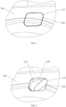
FIG. 1 is a partial schematic view of a body shell according to one embodiment of the present invention; -
FIG. 2 is a state diagram in which a charging opening is partially opened according to one embodiment of the present invention; -
FIG. 3 is a schematic structural view of a charging opening box according to one embodiment of the present invention; -
FIG. 4 is a schematic diagram of a positional relationship between a charging opening cover and a charging opening box according to one embodiment of the present invention; -
FIG. 5 is a schematic diagram of a connection structure of a charging opening cover and a charging opening box according to one embodiment of the present invention; -
FIG. 6 is a schematic diagram of a connection structure of a charging opening cover and a charging opening box according to another embodiment of the present invention; -
FIG. 7 is a cross-sectional view of the connection structure of the charging opening cover and the charging opening box inFIG. 6 ; -
FIG. 8 is a schematic diagram of a connection structure of a charging opening cover and a charging opening box according to yet another embodiment of the present invention; -
FIG. 9 is a cross-sectional view of the connection structure of the charging opening cover and the charging opening box inFIG. 8 ; -
FIG. 10 is a schematic diagram of a layout of quick and slow charging ports according to one embodiment of the present invention; and -
FIG. 11 is a schematic diagram of a layout of quick and slow charging ports according to another embodiment of the present invention. - 100. body shell; 110. charging opening; 200. charging opening cover; 210, rotation hinge; 211, connecting post; 212, slider; 300. driving device; 400, charging opening box; 410, port; 411, quick charging port; 412, slow charging port; 421, give-way opening; 422, boss; 423, chute; 500, sealing adhesive strip.
- Exemplary embodiments of the present disclosure will be described in more detail below with reference to the drawings. Although exemplary embodiments of the present disclosure are shown in the drawings, it should be understood that the present disclosure may be implemented in various forms and should not be limited by the embodiments set forth herein. On the contrary, these embodiments are provided for a more thorough understanding of the present disclosure, and can fully convey the scope of the present disclosure to those skilled in the art.
- Referring to
FIG. 1 to FIG. 9 , in order to solve the above problems, an embodiment of the present invention provides an opening/closing structure for acharging opening 110 of a vehicle and a vehicle having the opening/closing structure. - The vehicle may be a pure electric vehicle or a rechargeable hybrid vehicle, and it includes a
body shell 100, and acharging opening 110 is defined on thebody shell 100, and an opening/closing structure is provided at the chargingopening 110 for controllably opening or closing thecharging opening 110, thereby charging the vehicle. Of course, without deviating from the principle of the present invention, those skilled in the art may completely apply the opening/closing structure of the present invention to other scenarios, for example, it may also be used for an oil port of a vehicle. - The opening/closing structure in the embodiment of the present invention at least includes a charging
opening cover 200 and adriving device 300, where the chargingopening cover 200 is disposed on thebody shell 100 of the vehicle and configured to open or close the chargingopening 110 on thebody shell 100. Thedriving device 300 is disposed inside thebody shell 100 and connected with the chargingopening cover 200. Thedriving device 300 is configured to: first drive the chargingopening cover 200 in a closed state to sink inward from thebody shell 100, and then drive the chargingopening cover 200 to rotate, thereby at least partially opening thecharging opening 110 when the chargingopening 110 needs to be opened; and first drive the chargingopening cover 200 in an open state to rotate to align with the chargingopening 110, and then drive the chargingopening cover 200 to rise towards the outside of the body, thereby closing thecharging opening 110 when the chargingopening 110 needs to be closed. - In the opening/closing structure for the charging
opening 110 of the vehicle in the embodiment of the present invention, the chargingopening cover 200 is opened towards the inside of the body, which can ensure that the opening mode is full of sense of technology and fashion. Since the mode of opening towards the inside has less requirements on the appearance size, it can also reduce the restriction on gaps of the opening when modeling it, and improve the user experience. - In this embodiment, the charging
opening 110 may be designed to be approximately parallelogram, and correspondingly, the chargingopening cover 200 is also approximately parallelogram, and a size of the chargingopening cover 200 is slightly smaller than that of the chargingopening 110. Thedriving device 300 may be connected to an end of the chargingopening cover 200. In this way, in a process of driving the chargingopening cover 200 to rotate, the chargingopening cover 200 is opened in a fan-shaped manner, which can effectively reduce the occupation of an internal space of the body compared with a rail direct sliding opening mode. - Further, the opening/closing structure may also include a
charging opening box 400, which is covered on the charging opening 110 from the inside of thebody shell 100, and at least part of a side wall of the chargingopening box 400 has a first contour adapted to a rotation trajectory of an end of the chargingopening cover 200. An inner side of the chargingopening cover 200 is connected with arotation hinge 210, and thedriving device 300 is connected with the chargingopening cover 200 through therotation hinge 210. In the process that the chargingopening cover 200 is driven to be rotated, therotation hinge 210 is slidably connected with the side wall of the chargingopening box 400 having the first contour. - It is to be noted that the so-called first contour means that the side wall of the charging
opening box 400 is correspondingly designed into an arc-shaped side wall according to the arc-shaped moving trajectory of the end of the chargingopening box 200 during the rotation of the chargingopening cover 200 according to a certain rotation radius, so that the chargingopening cover 200 can always be slidably connected with the side wall of the chargingopening box 400 during the rotation of the chargingopening cover 200. For example, referring toFIG. 4 , in the process of driving the chargingopening cover 200 to rotate counterclockwise, a left lower end of the chargingopening cover 200 is always slidably connected with the side wall of the chargingopening box 400 having the first contour. - It may be understood that in a case in which the
charging opening box 400 is not disposed, when thedriving device 300 drives the chargingopening cover 200 to rotate, the chargingopening cover 200 has no connection relationship with other parts, which is rotated in a suspended manner correspondingly. In a case in which thecharging opening box 400 is disposed, when thedriving device 300 drives the chargingopening cover 200 to rotate, the chargingopening cover 200 is also slidably connected with the side wall of the chargingopening box 400 through therotation hinge 210. So that the side wall of the chargingopening box 400 can play a certain structural support role for the chargingopening cover 200, and the joint between the drivingdevice 300 and the chargingopening cover 200 is not easy to break, which improves the rigidity and stability of the whole opening/closing structure. - The charging
opening box 400 may be a plastic piece, and the color may be painted according to the vehicle to reduce the color difference. The chargingopening box 400 is approximately in a bowl-shaped structure, a size of a rim of the bowl is larger than that of the chargingopening 110, and the chargingopening box 400 is covered on the charging opening 110 from the inside of the body and cannot be rotated. Aport 410 is disposed in the bottom (a side facing away from the body shell 100) of the chargingopening box 400, and theport 410 is used for a charging base inside the body to extend outwards into the chargingopening box 400 for charging. - The
rotation hinge 210 may be in a plate-shape structure, fixedly connected to the inner side of the chargingopening cover 200, or detachably connected with the chargingopening cover 200 by a snap. A connectingpost 211 is disposed at one end of the rotation hinge 210 (in this embodiment, a right upper end of the rotation hinge 210). Thedriving device 300 may be a rotating motor with an output shaft that is reciprocatingly stretchable, and its output shaft is coaxially connected with the connectingpost 211. By driving therotation hinge 210 to rotate, the charging opening cover is driven to move synchronously. - In an optional embodiment, the side wall of the charging
opening box 400 having the first contour is provided with a penetrating give-way opening 421 extending along a circumferential direction of the chargingopening box 400, and an end of therotation hinge 210 is provided with aslider 212 extending in perpendicular to a rotating axis of the chargingopening cover 200, and theslider 212 is slidably connected within the give-way opening 421. - Considering that in the process of opening the
charging opening 110, the drivingdevice 300 first drives the chargingopening cover 200 to sink inward from thebody shell 100, therefore, the give-way opening 421 may extend from outside to inside along the side wall of the chargingopening box 400, and then extend along the rotation trajectory, so that theslider 212 is always slidably connected within the give-way opening 421 during thedriving device 300 driving the chargingopening cover 200 to move. - In another optional embodiment, an inner side of the side wall of the charging
opening box 400 having the first contour is provided with aboss 422, and a side of theboss 422 facing the inside of the chargingopening box 400 is provided with achute 423 extending along the circumferential direction of the chargingopening box 400. An end of therotation hinge 210 is provided with aslider 212 extending in perpendicular to the rotating axis of the chargingopening cover 200, and theslider 212 is slidably connected within thechute 423. - Specifically, the
boss 422 may include two protruded ridges in an up-down arrangement in a height direction of the chargingopening box 400, and an interval between the two protruded ridges forms achute 423. Or, theboss 422 is in an integral solid strip structure, integrally formed with the chargingopening box 400, and a side of theboss 422 facing the inside of the chargingopening box 400 is provided with thechute 423. - In yet another optional embodiment, the sidewall of the charging
opening box 400 having the first contour is provided with aboss 422 protruding towards the inside of the chargingopening box 400, and one side of theboss 422 facing the chargingopening 110 is provided with achute 423 extending along the circumferential direction of the chargingopening box 400, and therotation hinge 210 is provided with aslider 212 extending in parallel to the rotating axis of the chargingopening cover 200, and theslider 212 is slidably connected within thechute 423. - Specifically, the side wall of the charging
opening box 400 having the first contour protrudes toward the inside of the chargingopening box 400 to form theboss 422. A mesa of theboss 422 adjacent to thecharging opening 110 is recessed toward a side facing away from the chargingopening 110 to form thechute 423. - In a specific implementation, a
quick charging port 411 and aslow charging port 412 for charging by a charging gun are disposed in thecharging opening box 400 according to a first standard, and thequick charging port 411 and the slow chargingport 412 are disposed up and down in the same column. Thedriving device 300 is further configured to drive the chargingopening cover 200 to rotate by a first rotation angle so as to at least completely expose thequick charging port 411 and the slow chargingport 412. - In practical application, the first standard is the same as the European standard, and the
quick charging port 411 and the slow chargingport 412 may be used for charging by a charging gun meeting the European standard. In a case that the chargingopening 110 is approximately parallelogram, the chargingopening cover 200 is approximately parallelogram, and the driving motor is connected to the upper right end of therotation hinge 210, when the driving motor drives therotation hinge 210 to rotate the chargingopening cover 200 counterclockwise by 70°, thequick charging port 411 and the slow chargingport 412 in an up-down arrangement can be completely exposed. - In another specific implementation, the
quick charging port 411 and the slow chargingport 412 for charging by a charging gun are disposed in thecharging opening box 400 according to a second standard, and thequick charging port 411 and the slow chargingport 412 are disposed side by side from left to right. Thedriving device 300 is further configured to drive the chargingopening cover 200 to rotate by a second rotation angle, so as to at least completely expose thequick charging port 411 and the slow chargingport 412. - In practical application, the second standard is the same as the Chinese standard, and the
quick charging port 411 and the slow chargingport 412 may be used for charging by a charging gun meeting the Chinese standard. In a case in which thecharging opening 110 is approximately parallelogram, the chargingopening cover 200 is approximately parallelogram and the driving motor is connected to the right upper end of therotation hinge 210, when the driving motor drives therotation hinge 210 to rotate the chargingopening cover 200 counterclockwise by 110°, thequick charging port 411 and the slow chargingport 412 in left-right arrangement may be exposed. - A periphery of a side of the charging
opening box 400 facing thebody shell 100 has a turning edge, and a sealingadhesive strip 500 is disposed between the turning edge and thebody shell 100, and the chargingopening box 400 is bonded and fixed to thebody shell 100 through the sealingadhesive strip 500. The chargingopening box 400 may not only provide a certain structural support for the rotation of the chargingopening cover 200, but also may play a dustproof and waterproof role for thequick charging opening 411 and theslow charging opening 412. - The charging
opening box 400 covers the inner side of the chargingopening cover 200, and the chargingopening cover 200 and therotation hinge 210 rotate in thecharging opening box 400, and the chargingopening box 400 may be designed into different shapes according to the different motion trajectories of the chargingopening cover 200. The driving motor provides power for the movement of the chargingopening cover 200, and the chargingopening cover 200 may be rotated to an invisible area inside thebody shell 100. - It can be said that the opening/closing structure for the charging
opening 110 of the vehicle in the embodiments of the present invention not only has the advantages of the internally sliding track type and the outward rotatingly opening type, but also avoids the disadvantages of both, which can meet the urgent demand of the market and improve the user experience. - According to any one of the above optional embodiments or the combination of multiple optional embodiments, the embodiments of the present invention can achieve the following beneficial effects.
- In the opening/closing structure of the vehicle and its
charging opening 110 in the embodiments of the present invention, the chargingopening cover 200 is rotated and opened towards the inside of the body, so that the opening mode can be ensured to be full of sense of technology and fashion. Because the mode of opening towards the inside has less requirements on the appearance size, the size of the chargingopening 110 can be made smaller, which can also reduce the restriction on gaps of the opening when modeling it and improve the user experience. In addition, compared with the internally sliding track type, the rotatable opening mode can save internal air conditioning and improve space utilization. - Further, in the vehicle and the opening/closing structure for the charging
opening 110 of the vehicle in the embodiments of the present invention, when thedriving device 300 drives the chargingopening cover 200 to rotate, the chargingopening cover 200 is also slidably connected with the side wall of the chargingopening cover box 400 through therotation hinge 210, so that the side wall of the chargingopening cover box 400 can play a certain structural support role for the chargingopening cover 200, and the joint between the drivingdevice 300 and the chargingopening cover 200 is not easy to break, which improves the rigidity and stability of the whole opening/closing structure. - Therefore, those skilled in the art should realize that although a plurality of exemplary embodiments of the present invention have been shown and described in detail herein, other variations or modifications in accord with the principle of the present invention may be directly determined or deduced according to the present disclosure of the present invention without departing from the spirit and scope of the present invention. Therefore, the scope of the present invention should be understood and considered to cover all such other variations or modifications.
Claims (12)
- An opening/closing structure for a charging opening of a vehicle, comprising:a charging opening cover, disposed on a body shell of the vehicle and configured to open or close a charging opening on the body shell; anda driving device, disposed inside the body shell, connected with the charging opening cover, and configured to: first drive the charging opening cover in a closed state to sink inwards from the body shell, and then drive the charging opening cover to rotate, thereby at least partially open the charging opening when the charging opening needs to be opened; first drive the charging opening cover in an open state to rotate to align with the charging opening, and then drive the charging opening cover to rise towards the outside of the body, thereby closing the charging opening when the charging opening needs to be closed.
- The opening/closing structure for the charging opening of the vehicle according to claim 1, further comprising:a charging opening box, covered on the charging opening from the inside of the body shell, wherein at least part of a side wall of the charging opening box has a first contour adapted to a rotation trajectory of an end of the charging opening cover;an inner side of the charging opening cover is connected with a rotation hinge, and the driving device is connected with the charging opening cover through the rotation hinge, and in a process that the charging opening cover is driven to be rotated, the rotation hinge is slidably connected with the side wall of the charging opening box having the first contour.
- The opening/closing structure for the charging opening of the vehicle according to claim 2, wherein
the rotation hinge is provided with a connecting post, the driving device is a rotating motor with an output shaft that is reciprocatingly stretchable, and the output shaft of the rotating motor is coaxially connected with the connecting post. - The opening/closing structure for the charging opening of the vehicle according to claim 2, wherein
the side wall of the charging opening box having the first contour is provided with a penetrating give-way opening extending along a circumferential direction of the charging opening box, and an end of the rotation hinge is provided with a slider extending in perpendicular to a rotating axis of the charging opening cover, and the slider is slidably connected within the give-way opening. - The opening/closing structure for the charging opening of the vehicle according to claim 2, wherein
an inner side of the side wall of the charging opening box having the first contour is provided with a boss, a side of the boss facing the inside of the charging opening box is provided with a chute extending along the circumferential direction of the charging opening box, and an end of the rotation hinge is provided with a slider extending in perpendicular to a rotating axis of the charging opening cover, and the slider is slidably connected within the chute. - The opening/closing structure for the charging opening of the vehicle according to claim 5, wherein
the boss comprises two protruded ridges arranged up and down in a height direction of the charging opening box, and an interval between the two protruded ridges forms the chute. - The opening/closing structure for the charging opening of the vehicle according to claim 2, wherein an inner side of the side wall of the charging opening box having the first contour is provided with a boss, a side of the boss facing the charging opening is provided with a chute extending along the circumferential direction of the charging opening box, and the rotation hinge is provided with a slider extending in parallel to a rotating axis of the charging opening cover, and the slider is slidably connected within the chute.
- The opening/closing structure for the charging opening of the vehicle according to claim 7, whereinthe inner side of the side wall of the charging opening box having the first contour protrudes towards the inside of the charging opening box to form the boss; anda mesa of the boss adjacent to the charging opening is recessed toward a side facing away from the charging opening to form the chute.
- The opening/closing structure for the charging opening of the vehicle according to claim 2, wherein
a sealing adhesive strip is disposed between an edge of a side of the charging opening box facing the body shell and the body shell. - The opening/closing structure for the charging opening of the vehicle according to claim 2, whereina quick charging port and a slow charging port for charging by a charging gun are disposed in the charging opening box according to a first standard, and the quick charging port and the slow charging port are disposed up and down in a same column; andthe driving device is further configured to drive the charging opening cover to rotate for a first rotation angle so as to at least completely expose the quick charging port and the slow charging port.
- The opening/closing structure for the charging opening of the vehicle according to claim 2, whereina quick charging port and a slow charging port for charging by a charging gun are disposed in the charging opening box according to a second standard, and the quick charging port and the slow charging port are disposed side by side from left to right; andthe driving device is further configured to drive the charging opening cover to rotate for a second rotation angle so as to at least completely expose the quick charging port and the slow charging port.
- A vehicle comprising a body shell provided with the opening/closing structure for the charging opening of the vehicle according to any one of claims 1 to 11.
Applications Claiming Priority (1)
| Application Number | Priority Date | Filing Date | Title |
|---|---|---|---|
| PCT/CN2021/137134 WO2023102902A1 (en) | 2021-12-10 | 2021-12-10 | Vehicle and opening/closing structure of charging port thereof |
Publications (4)
| Publication Number | Publication Date |
|---|---|
| EP4446160A1 true EP4446160A1 (en) | 2024-10-16 |
| EP4446160A4 EP4446160A4 (en) | 2025-02-12 |
| EP4446160B1 EP4446160B1 (en) | 2026-03-18 |
| EP4446160C0 EP4446160C0 (en) | 2026-03-18 |
Family
ID=86729462
Family Applications (1)
| Application Number | Title | Priority Date | Filing Date |
|---|---|---|---|
| EP21966823.3A Active EP4446160B1 (en) | 2021-12-10 | 2021-12-10 | Vehicle and opening/closing structure of charging port thereof |
Country Status (3)
| Country | Link |
|---|---|
| EP (1) | EP4446160B1 (en) |
| CN (1) | CN118139761A (en) |
| WO (1) | WO2023102902A1 (en) |
Families Citing this family (1)
| Publication number | Priority date | Publication date | Assignee | Title |
|---|---|---|---|---|
| CN116971688B (en) * | 2023-06-26 | 2026-03-13 | 上海毓恬冠佳科技股份有限公司 | An opening and closing structure for a car charging port door and a car |
Family Cites Families (11)
| Publication number | Priority date | Publication date | Assignee | Title |
|---|---|---|---|---|
| DE202011050412U1 (en) * | 2011-06-10 | 2011-08-17 | Richard Fritz Gmbh + Co. Kg | Tank cover unit for a motor vehicle |
| DE102011090205A1 (en) * | 2011-12-30 | 2013-07-04 | Dr. Ing. H.C. F. Porsche Ag | Plug element for locking openable aperture that is utilized as e.g. tank recess for accommodation of tank connecting piece of electric vehicle, has displaceable element displaced into movement section of superimposed movements by drive unit |
| WO2016020239A1 (en) * | 2014-08-05 | 2016-02-11 | Autotest Spa Ag | Closure of a niche recessed in a motor vehicle body panel |
| JP6493659B2 (en) * | 2014-11-19 | 2019-04-03 | 三菱自動車工業株式会社 | Charging port structure |
| DE102017101247A1 (en) * | 2017-01-24 | 2018-07-26 | Dr. Ing. H.C. F. Porsche Aktiengesellschaft | Loading door unit |
| DE102017008108B4 (en) * | 2017-08-26 | 2021-09-02 | Daimler Ag | Closure device for closing a through opening in a vehicle body and vehicle with such a closure device |
| DE102018109474A1 (en) * | 2018-04-20 | 2019-10-24 | Dr. Ing. H.C. F. Porsche Aktiengesellschaft | Charging socket cover for an electrically operated motor vehicle |
| DE102019132408B4 (en) * | 2019-11-29 | 2021-11-04 | Dr. Ing. H.C. F. Porsche Aktiengesellschaft | Charging interface with an electromagnetically movable cover for electrically charging a traction battery of a motor vehicle and motor vehicle with such a charging interface |
| CN212737791U (en) * | 2020-08-20 | 2021-03-19 | 东风小康汽车有限公司重庆分公司 | A charging port socket fixing structure |
| CN212423300U (en) * | 2020-09-09 | 2021-01-29 | 宁波百德汽车饰件有限公司 | Interior hidden little door that charges |
| CN214607740U (en) * | 2021-01-14 | 2021-11-05 | 河南路臻泰环保科技有限公司 | Automatic opening and closing structure of new energy automobile charging opening cover |
-
2021
- 2021-12-10 WO PCT/CN2021/137134 patent/WO2023102902A1/en not_active Ceased
- 2021-12-10 CN CN202180103619.3A patent/CN118139761A/en active Pending
- 2021-12-10 EP EP21966823.3A patent/EP4446160B1/en active Active
Also Published As
| Publication number | Publication date |
|---|---|
| EP4446160B1 (en) | 2026-03-18 |
| WO2023102902A1 (en) | 2023-06-15 |
| EP4446160A4 (en) | 2025-02-12 |
| CN118139761A (en) | 2024-06-04 |
| EP4446160C0 (en) | 2026-03-18 |
Similar Documents
| Publication | Publication Date | Title |
|---|---|---|
| EP4446160B1 (en) | Vehicle and opening/closing structure of charging port thereof | |
| EP4464229A1 (en) | Automatic cleaning apparatus and system | |
| US20240131982A1 (en) | Concealed roof light and vehicle | |
| CN212362382U (en) | Air duct assembly and air conditioner | |
| CN103185390A (en) | Air conditioner, air outlet sliding cover device thereof and control method of air outlet sliding cover device | |
| CN202382382U (en) | Air conditioner and air outlet sliding cover device thereof | |
| CN207496591U (en) | Unmanned plane landing platform, the visual field expansion system of vehicle and vehicle | |
| WO2022226694A1 (en) | Electric charging port and electric vehicle | |
| CN204243092U (en) | A kind of storage battery access cover device | |
| CN209402300U (en) | A kind of external rotor electric machine with dustproof and waterproof function | |
| CN111017042B (en) | Charging opening cover with four-connecting-rod automatic opening and closing mechanism | |
| US20250146349A1 (en) | Opening and closing cover assembly for opening portion of automobile body | |
| CN219619230U (en) | Left-right opening and closing structure of automobile engine cover | |
| CN214099783U (en) | An electric energy meter external battery box assembly | |
| CN210910036U (en) | Robot head and neck movement mechanism | |
| CN107587801B (en) | Push-type secondary opening mechanism for charging port cover of pure electric vehicle | |
| CN210951774U (en) | Air port structure and air conditioner | |
| CN212961890U (en) | Air conditioner indoor unit and air conditioner | |
| CN216759892U (en) | Self-moving robot | |
| CN222698577U (en) | Multi-functional tail threshold and car | |
| CN222984706U (en) | A keep away empty door that is used for automatic baking finish room that spouts of rail transit vehicle | |
| CN214341840U (en) | Container cover and cooking utensil | |
| CN222737423U (en) | Intelligent opening and closing autonomous moving luggage case | |
| CN220682238U (en) | Solar dining car | |
| CN217134755U (en) | Charging connection structure applied to electric vehicle |
Legal Events
| Date | Code | Title | Description |
|---|---|---|---|
| STAA | Information on the status of an ep patent application or granted ep patent |
Free format text: STATUS: THE INTERNATIONAL PUBLICATION HAS BEEN MADE |
|
| PUAI | Public reference made under article 153(3) epc to a published international application that has entered the european phase |
Free format text: ORIGINAL CODE: 0009012 |
|
| STAA | Information on the status of an ep patent application or granted ep patent |
Free format text: STATUS: REQUEST FOR EXAMINATION WAS MADE |
|
| 17P | Request for examination filed |
Effective date: 20240528 |
|
| AK | Designated contracting states |
Kind code of ref document: A1 Designated state(s): AL AT BE BG CH CY CZ DE DK EE ES FI FR GB GR HR HU IE IS IT LI LT LU LV MC MK MT NL NO PL PT RO RS SE SI SK SM TR |
|
| A4 | Supplementary search report drawn up and despatched |
Effective date: 20250114 |
|
| RIC1 | Information provided on ipc code assigned before grant |
Ipc: B60K 15/05 20060101ALI20250108BHEP Ipc: B62D 25/24 20060101ALI20250108BHEP Ipc: B60L 53/16 20190101AFI20250108BHEP |
|
| DAV | Request for validation of the european patent (deleted) | ||
| DAX | Request for extension of the european patent (deleted) | ||
| GRAP | Despatch of communication of intention to grant a patent |
Free format text: ORIGINAL CODE: EPIDOSNIGR1 |
|
| STAA | Information on the status of an ep patent application or granted ep patent |
Free format text: STATUS: GRANT OF PATENT IS INTENDED |
|
| INTG | Intention to grant announced |
Effective date: 20251113 |
|
| GRAS | Grant fee paid |
Free format text: ORIGINAL CODE: EPIDOSNIGR3 |
|
| GRAA | (expected) grant |
Free format text: ORIGINAL CODE: 0009210 |
|
| STAA | Information on the status of an ep patent application or granted ep patent |
Free format text: STATUS: THE PATENT HAS BEEN GRANTED |
|
| AK | Designated contracting states |
Kind code of ref document: B1 Designated state(s): AL AT BE BG CH CY CZ DE DK EE ES FI FR GB GR HR HU IE IS IT LI LT LU LV MC MK MT NL NO PL PT RO RS SE SI SK SM TR |
|
| REG | Reference to a national code |
Ref country code: CH Ref legal event code: F10 Free format text: ST27 STATUS EVENT CODE: U-0-0-F10-F00 (AS PROVIDED BY THE NATIONAL OFFICE) Effective date: 20260318 Ref country code: GB Ref legal event code: FG4D |
|
| REG | Reference to a national code |
Ref country code: DE Ref legal event code: R096 Ref document number: 602021050445 Country of ref document: DE |
|
| REG | Reference to a national code |
Ref country code: IE Ref legal event code: FG4D |