EP4446145A1 - Open-roof assembly comprising a lighting assembly and a contact-free switch therefor - Google Patents
Open-roof assembly comprising a lighting assembly and a contact-free switch therefor Download PDFInfo
- Publication number
- EP4446145A1 EP4446145A1 EP24169456.1A EP24169456A EP4446145A1 EP 4446145 A1 EP4446145 A1 EP 4446145A1 EP 24169456 A EP24169456 A EP 24169456A EP 4446145 A1 EP4446145 A1 EP 4446145A1
- Authority
- EP
- European Patent Office
- Prior art keywords
- closure member
- open
- switch device
- roof
- roof assembly
- Prior art date
- Legal status (The legal status is an assumption and is not a legal conclusion. Google has not performed a legal analysis and makes no representation as to the accuracy of the status listed.)
- Granted
Links
Images

Classifications
-
- B—PERFORMING OPERATIONS; TRANSPORTING
- B60—VEHICLES IN GENERAL
- B60J—WINDOWS, WINDSCREENS, NON-FIXED ROOFS, DOORS, OR SIMILAR DEVICES FOR VEHICLES; REMOVABLE EXTERNAL PROTECTIVE COVERINGS SPECIALLY ADAPTED FOR VEHICLES
- B60J7/00—Non-fixed roofs; Roofs with movable panels, e.g. rotary sunroofs
- B60J7/02—Non-fixed roofs; Roofs with movable panels, e.g. rotary sunroofs of sliding type, e.g. comprising guide shoes
- B60J7/04—Non-fixed roofs; Roofs with movable panels, e.g. rotary sunroofs of sliding type, e.g. comprising guide shoes with rigid plate-like element or elements, e.g. open roofs with harmonica-type folding rigid panels
- B60J7/047—Non-fixed roofs; Roofs with movable panels, e.g. rotary sunroofs of sliding type, e.g. comprising guide shoes with rigid plate-like element or elements, e.g. open roofs with harmonica-type folding rigid panels movable to overlapping or nested relationship
-
- B—PERFORMING OPERATIONS; TRANSPORTING
- B60—VEHICLES IN GENERAL
- B60Q—ARRANGEMENT OF SIGNALLING OR LIGHTING DEVICES, THE MOUNTING OR SUPPORTING THEREOF OR CIRCUITS THEREFOR, FOR VEHICLES IN GENERAL
- B60Q3/00—Arrangement of lighting devices for vehicle interiors; Lighting devices specially adapted for vehicle interiors
- B60Q3/80—Circuits; Control arrangements
- B60Q3/82—Switches specially adapted for vehicle interior lighting, e.g. switching by tilting the lens
-
- B—PERFORMING OPERATIONS; TRANSPORTING
- B60—VEHICLES IN GENERAL
- B60J—WINDOWS, WINDSCREENS, NON-FIXED ROOFS, DOORS, OR SIMILAR DEVICES FOR VEHICLES; REMOVABLE EXTERNAL PROTECTIVE COVERINGS SPECIALLY ADAPTED FOR VEHICLES
- B60J7/00—Non-fixed roofs; Roofs with movable panels, e.g. rotary sunroofs
- B60J7/02—Non-fixed roofs; Roofs with movable panels, e.g. rotary sunroofs of sliding type, e.g. comprising guide shoes
- B60J7/04—Non-fixed roofs; Roofs with movable panels, e.g. rotary sunroofs of sliding type, e.g. comprising guide shoes with rigid plate-like element or elements, e.g. open roofs with harmonica-type folding rigid panels
- B60J7/043—Sunroofs e.g. sliding above the roof
-
- B—PERFORMING OPERATIONS; TRANSPORTING
- B60—VEHICLES IN GENERAL
- B60Q—ARRANGEMENT OF SIGNALLING OR LIGHTING DEVICES, THE MOUNTING OR SUPPORTING THEREOF OR CIRCUITS THEREFOR, FOR VEHICLES IN GENERAL
- B60Q3/00—Arrangement of lighting devices for vehicle interiors; Lighting devices specially adapted for vehicle interiors
- B60Q3/20—Arrangement of lighting devices for vehicle interiors; Lighting devices specially adapted for vehicle interiors for lighting specific fittings of passenger or driving compartments; mounted on specific fittings of passenger or driving compartments
- B60Q3/208—Sun roofs; Windows
-
- B—PERFORMING OPERATIONS; TRANSPORTING
- B60—VEHICLES IN GENERAL
- B60Q—ARRANGEMENT OF SIGNALLING OR LIGHTING DEVICES, THE MOUNTING OR SUPPORTING THEREOF OR CIRCUITS THEREFOR, FOR VEHICLES IN GENERAL
- B60Q3/00—Arrangement of lighting devices for vehicle interiors; Lighting devices specially adapted for vehicle interiors
- B60Q3/50—Mounting arrangements
- B60Q3/51—Mounting arrangements for mounting lighting devices onto vehicle interior, e.g. onto ceiling or floor
-
- B—PERFORMING OPERATIONS; TRANSPORTING
- B60—VEHICLES IN GENERAL
- B60Q—ARRANGEMENT OF SIGNALLING OR LIGHTING DEVICES, THE MOUNTING OR SUPPORTING THEREOF OR CIRCUITS THEREFOR, FOR VEHICLES IN GENERAL
- B60Q3/00—Arrangement of lighting devices for vehicle interiors; Lighting devices specially adapted for vehicle interiors
- B60Q3/70—Arrangement of lighting devices for vehicle interiors; Lighting devices specially adapted for vehicle interiors characterised by the purpose
- B60Q3/74—Arrangement of lighting devices for vehicle interiors; Lighting devices specially adapted for vehicle interiors characterised by the purpose for overall compartment lighting; for overall compartment lighting in combination with specific lighting, e.g. room lamps with reading lamps
-
- H—ELECTRICITY
- H03—ELECTRONIC CIRCUITRY
- H03K—PULSE TECHNIQUE
- H03K17/00—Electronic switching or gating, i.e. not by contact-making and –breaking
- H03K17/94—Electronic switching or gating, i.e. not by contact-making and –breaking characterised by the way in which the control signals are generated
- H03K17/945—Proximity switches
- H03K17/95—Proximity switches using a magnetic detector
- H03K17/9517—Proximity switches using a magnetic detector using galvanomagnetic devices
-
- H—ELECTRICITY
- H03—ELECTRONIC CIRCUITRY
- H03K—PULSE TECHNIQUE
- H03K17/00—Electronic switching or gating, i.e. not by contact-making and –breaking
- H03K17/94—Electronic switching or gating, i.e. not by contact-making and –breaking characterised by the way in which the control signals are generated
- H03K17/945—Proximity switches
- H03K17/95—Proximity switches using a magnetic detector
- H03K17/952—Proximity switches using a magnetic detector using inductive coils
Definitions
- the invention relates to an open-roof assembly comprising a lighting assembly and a contact-free switch therefor. Further, the invention relates to a vehicle comprising said open-roof assembly.
- the open-roof assembly is well-known.
- the open-roof assembly is configured to be mounted in a vehicle roof and comprises at least one moveably arranged closure member.
- the closure member is configured and arranged to cover an opening in the vehicle roof or at least partly uncover the opening in the vehicle roof.
- the closure member is a transparent panel and comprises glass or a suitable plastic.
- the closure member may be configured to tilt or to slide.
- the closure member is supported in a guide assembly.
- the guide assembly may be adapted to raise a rear edge of the closure member to provide for a tilted position. From the tilted position, the guide assembly may be adapted to slide the closure member rearward to provide an open position, in which the opening in the vehicle roof is at least partly uncovered.
- a known open-roof assembly comprises a lighting assembly.
- the lighting assembly may be configured to inject light into a glass panel of the closure member such that it may appear that the glass panel is lit.
- Other lighting assemblies are known as well such as a lighting assembly providing ring-shaped lighting below the glass panel or even below the opening in the vehicle roof.
- the object is achieved in an open-roof assembly for covering or at least partly uncovering an opening in a vehicle roof according to claim 1.
- the open-roof assembly comprises a moveably arranged closure member, a lighting assembly and a frame member.
- the lighting assembly comprises a switch device and a light source.
- the switch device is configured and arranged to either detect presence of a detectable part of the open-roof assembly relative to the switch device without physically contacting the detectable part, when the closure member is in a closed position covering the opening in the vehicle roof, or to detect absence of the detectable part, when the closure member is in a position at least partly uncovering the opening in the vehicle roof.
- the lighting assembly is configured to switch off the light source, when the switch device detects absence of the detectable part.
- the switch device comprises a Hall sensor and the detectable part comprises a magnetic element.
- a Hall sensor is well-known, simple and cost-effective element to detect the presence of a magnetic field. Moving the Hall sensor and the magnetic element relative to each other enables to detect whether the magnetic element and the Hall sensor are aligned, e.g. when the closure member is in the closed position, or are not aligned, e.g. when the closure member is in a position in which position the opening in the vehicle roof is at least partly uncovered.
- the switch device comprises a Hall sensor and a magnetic element, wherein the magnetic element is arranged at a first side of the Hall sensor and the detectable part comprises a ferrometal.
- the detectable part is arranged at a second side of the Hall sensor, when the closure member is in the closed position, the second side being opposite of the first side.
- the closure member comprises a support frame comprising a ferrometal component, e.g. comprising steel. Arranging a magnetic element at the first side of the Hall sensor, presence of a ferrometal component at the second side of the Hall sensor is detectable.
- the support frame may extend over a large length compared to the size of the Hall sensor. Hence, placement of the Hall sensor and the detectable part may be less susceptible to alignment errors.
- the switch device comprises a capacitive sensor.
- a capacitive sensor is enabled to detect the presence or absence of a large range of different materials. Thus, in this embodiment, more design freedom with respect to material use is obtained.
- the switch device comprises an inductive sensor and the detectable part comprises a ferrometal.
- An inductive sensor is a simple and cost-effective sensor for detecting presence or absence of a ferrometal component such as a steel frame, or the like.
- the lighting assembly comprises a first switch device and a second switch device, the lighting assembly being configured to switch off the light source, when either one of the first and second switch device detects absence of the detectable part.
- a second switch device may be used to provide redundancy and thus a more reliable operation. If one switch device would fail, the second switch device is likely to still function properly.
- the switch device is arranged on the frame member, the detectable part being arranged on the closure member.
- the switch device is mounted on the closure member, the detectable part being arranged on the frame member.
- the switch device may be mounted either on the frame member or on the closure member and, respectively, the detectable part may be part of the closure member or be part of the frame member.
- a size of the switch device may be taken into consideration in view of availability of mounting space for the switch device. Other considerations may be taken into consideration instead or as well.
- the frame member is arranged in a frame plane and the closure member is arranged in the frame plane, when the closure member is in the closed position.
- the closure member comprises a front end and a rear end, wherein the closure member is rotatable at the front end to move the rear end out of the frame plane to a tilted position.
- the switch device is arranged either on the rear end of the closure member or on an edge section of the frame member adjacent to the rear end of the closure member, when the closure member is in the closed position. If the light is to be switched off, when the closure member is in the tilted position, it may be suitable to arrange the switch device at a position where the closure member moves out of the frame plane to enable simple detection of the tilted position.
- the frame member is arranged in a frame plane and the closure member is arranged in the frame plane, when the closure member is in the closed position.
- the closure member comprises a front end and a rear end, wherein the closure member is rotatable at the front end to move the rear end out of the frame plane to a tilted position, and wherein the closure member is slidable to move the closure member out of the frame plane to an open position.
- the switch device is arranged either on a front end of the closure member or on an edge section of the frame member adjacent to the front end of the closure member, when the closure member is in the closed position.
- the switch device may be suitable to arrange the switch device at a position where the closure member stays in the frame plane, when the closure member is in the tilted position, and where the closure member moves out of the frame plane, when the closure member slides to the open position.
- a vehicle comprising the above-described open-roof assembly.
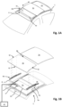
- Fig. 1A illustrates a vehicle roof 1 having an open roof assembly arranged therein.
- the open roof assembly comprises a moveable panel 2a and a fixed panel 2b.
- the moveable panel 2a is also referred to as a closure member, since the moveable panel 2a is moveable over a first roof opening 3a such to enable to open and to close the first roof opening 3a.
- a wind deflector 4 is arranged at a front side of the first roof opening 3a.
- the moveable panel 2a may be in a closed position, which is a position wherein the moveable panel 2a is arranged over and closes the first roof opening 3a and thus usually is arranged in a plane of the vehicle roof 1. Further, the moveable panel 2a may be in a tilted position, which is a position wherein a rear end RE of the moveable panel 2a is raised as compared to the closed position, while a front end FE of the moveable panel 2a is still in the closed position. Further, the moveable panel 2a may be in an open position, which is a position wherein the moveable panel 2a is slid open and the first roof opening 3a is partly or completely exposed.
- the illustrated vehicle roof 1 corresponds to a passenger car.
- the present invention is however not limited to passenger cars. Any other kind of vehicles that may be provided with a moveable panel are contemplated as well.
- Fig. 1B illustrates the same vehicle roof as shown in Fig. 1A having panels 2a and 2b.
- Fig. 1A shows the open roof assembly in the open position
- Fig. 1B is an exploded view of the open roof assembly in a closed position. Further, in this exploded view of Fig. 1B , it is shown that there is a second roof opening 3b.
- the first and second roof openings 3a, 3b are provided in a frame 5 of the open roof assembly. An edge 5a of the frame 5 defines the first roof opening 3a.
- the second roof opening 3b is arranged under the fixed panel 2b such that light may enter a vehicle interior passenger compartment through the fixed panel 2b, presuming that the fixed panel 2b is a glass panel or a similarly transparent panel, for example made of a plastic material or any other suitable material.
- the second roof opening 3b with a transparent or translucent fixed panel 2b is optional and may be omitted in another embodiment of the open roof assembly.
- the wind deflector 4 is commonly a flexible material, e.g. a woven or non-woven cloth having through holes arranged therein or a web or net.
- the flexible material is supported by a support structure 4a, e.g. a bar-like or tube-like structure, which structure is hingedly coupled, directly or indirectly, to the frame 5 at a hinge 4b.
- the wind deflector 4 is arranged in front of the first roof opening 3a and adapts air flow when the moveable panel 2a is in the open position. In its raised position, the wind deflector 4 reduces inconvenient noise due to air flow during driving. When the moveable panel 2a is in the closed position or in the tilted position, the wind deflector 4 is held down below the front end FE of the moveable panel 2a.
- the wind deflector 4 is raised by a spring force when the moveable panel 2a slides to an open position and the wind deflector 4 is pushed down by the moveable panel 2a when the moveable panel 2a slides back into its closed position.
- the moveable panel 2a is shown in an open position and the wind deflector 4 is shown in a raised position.
- Fig. 1B the moveable panel 2a is shown in a closed position and the wind deflector 4 is correspondingly shown in a position in which it is held down.
- Fig. 1B further illustrates a drive assembly having a first guide assembly 6a, a second guide assembly 6b, a first drive cable 7 and a second drive cable 8.
- the first and second guide assemblies 6a, 6b are arranged on respective side ends SE of the moveable panel 2a and may each comprise a guide and a mechanism.
- the guide is coupled to the frame 5, while the mechanism comprises moveable parts and is slideably moveable in the guide.
- the first and the second drive cables 7, 8 are provided between the mechanisms of the respective guide assemblies 6a, 6b and a electric motor 9.
- the drive cables 7, 8 couple the electric motor 9 to the mechanisms of the respective guide assemblies 6a, 6b such that upon operating the electric motor 9, the mechanisms start to move.
- a core of the drive cable 7, 8 is moved by the electric motor 9 such to push or pull on the mechanisms of the respective guides 6a, 6b.
- a drive assembly is well known in the art and is therefore not further elucidated herein.
- any other suitable drive assembly may be employed as well without departing from the scope of the present invention.
- an electric motor may be operatively arranged between the respective guides and the respective mechanisms of the guide assemblies 6a, 6b and, in such embodiment, a drive assembly may be omitted completely.
- the guide assemblies 6a, 6b may start movement with raising the rear end RE of the moveable panel 2a, thereby bringing the moveable panel 2a in the tilted position. Then, from the tilted position, the guide assemblies 6a, 6b may start to slide to bring the moveable panel 2a in the open position.
- the moveable panel 2a may be moveable to a tilted position by raising the rear end RE, while an open position is reached by first lowering the rear end RE and then sliding the moveable panel 2a under the fixed panel 2b or any other structure or element provided behind the rear end RE of the moveable panel 2a.
- the moveable panel 2a may be merely moveable between a closed position and a tilted position or between a closed position and an open position.
- the electric motor 9 is mounted near or below the front end FE of the moveable panel 2a at a recess 10. In another embodiment, the electric motor 9 may be positioned at any other suitable position or location. For example, the electric motor 9 may be arranged near or below the rear end RE of the moveable panel 2a or below the fixed panel 2b.
- a control module 11 is schematically illustrated and is operatively coupled to the electric motor 9.
- the control module 11 may be any kind of processing module, either a software controlled processing module or a dedicated processing module, like an ASIC, which are both well known to those skilled in the art.
- the control module 11 may be a stand-alone control module or it may be operatively connected to another control module, like a multipurpose, generic vehicle control module.
- the control module 11 may be embedded in or be part of such a generic vehicle control module.
- the control module 11 may be embodied by any control module suitable for, capable of and configured for performing operation of the electric motor 9 and thus the moveable roof assembly.
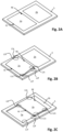
- Fig. 2A shows a schematic representation of the open-roof assembly of Fig. 1A .
- the open-roof assembly comprises a closure member 2a, herein also referred to as the moveable panel 2a, and comprises the fixed panel 2b. Further, the open-roof assembly comprises the frame 5.
- the closure member 2a comprises the front end FE and the rear end RE.
- the open-roof assembly is in a closed position.
- the closure member 2a is positioned in a frame plane.
- the frame plane is a plane defined by the frame 5.
- the frame plane may be curved.
- the first roof opening 3a is covered and closed by the closure member 2a.
- Fig. 2B shows the open-roof assembly of Fig. 2A in a tilted position.
- the closure member 2a In the tilted position, the closure member 2a is rotated at the front end FE and lifted at the rear end RE, thereby creating a gap at the rear end RE. Through the gap, air may flow between an interior compartment of the vehicle and an exterior of the vehicle, for example.
- Fig. 2C shows the open-roof assembly of Fig. 2A in an open position.
- the closure member 2a In the open position, the closure member 2a is lifted out of the frame plane and is shifted away from the first roof opening 3a such that the first roof opening 3a is almost completely open.
- the open-roof assembly may be provided with a lighting assembly.
- a light source of the lighting assembly may be switch on or off depending on the position of the closure member 2a. Thereto, the position of the closure member 2a may be monitored by a suitable switch device, which is illustrated in Figs. 3A - 3B in more detail.
- the switch device may be mounted at different positions relative to the frame 5 and the closure member 2a. For example, if the light source may be switched on, when the closure member 2a is in the closed position and the light source needs to be switched of in the tilted position and in the open position, the switch device may be mounted adjacent to or on the rear end of the closure member 2a. In more detail and with reference to Fig. 2B and 2C , the switch device may be mounted in a first configuration at a first rear end position L2c on the closure member 2a or in a second configuration at a first rear frame position L2f on the frame 5.
- the switch device may be mounted adjacent to or on the front end of the closure member 2a.
- the switch device may be mounted in a first configuration at a first front end position L1c on the closure member 2a or in a second configuration at a first front frame position L1f on the frame 5.
- redundancy may be introduced by mounting two switch devices and associated detectable parts.
- a first switch device may be mounted on the first rear frame position L2f and on a second rear frame position L3f, while respective detectable parts may be arranged at the first rear end position L2c and at a second rear end position L3c.
- the light source may be switched off. If one of the switches would fail, the light will still be switched off, when the closure member is in the tilted position or in the open position.
- a failing switch device behaves as a switch device always detecting absence of the detectable part, the light may still be switched on, when one of the two switch devices detects presence of the respective detectable part.
- a visual or audible error signal may be given.
- Fig. 3A shows a frame part 23 and a closure member 2a in a closed position.
- the closure member 2a comprises a support frame 21.
- the support frame 21 may comprise steel or another ferrometal comprising composition.
- the support frame 21 may be covered by a suitable plastic or rubber-like composition 22 as well known in the art.
- the closure member 2a further comprises a light source 33, which is a part of a lighting assembly.
- the lighting assembly further comprises a switch device 32 and a detectable part 31.
- the switch device 32 is a Hall sensor and the detectable part 31 is a magnetic element. The presence of the magnetic element 31 in front of the Hall sensor 32 is detectable by the Hall sensor 32. In the illustrated closed position, the Hall sensor 32 detects the presence of the magnetic element 31 and, thus, it is determined that the closure member 2a is in the closed position, allowing the lighting assembly to operate the light source 33.
- the light source 33 is arranged on a transparent panel, e.g. a glass or plastic panel, which forms a main component of the closure member 2a.
- Light emitted by the light source 33 may be direct light DL, directly illuminating an interior Int of the vehicle or the light may be emitted into the transparent panel as indirect light IL.
- the indirect light IL may travel through the transparent composition of the transparent panel and may couple out of the transparent panel at another location.
- Such indirect lighting is well known in the art and is not further elucidated herein.
- the light source may be mounted on the frame part 23, for example, either for direct lighting or for indirect lighting by reflection against the closure member 2a.
- Fig. 3B shows the embodiment of Fig. 3A , wherein the closure member 2a is in a tilted or open position.
- the detectable part 31 is moved with the closure member 2a out of the frame plane.
- the detectable part 31 is thus not in front of the switch device 32 and the switch device 32 switches off the operation of the light source 33. No light is emitted by the light source 33 as long as the detectable part 31 is not in front of the switch device 32, i.e. as long as the closure member 2a is in the tilted position or in the open position.
- Fig. 4A illustrates a second embodiment, wherein the main configuration of the open-roof assembly is similar to the configuration of the open-roof assembly of Figs. 3A - 3B , but the switch device 32 and the detectable part are differently configured.
- the detectable part is the support frame 23 comprising a ferrometal composition.
- the switch device 32 is a Hall sensor and, in the illustrated closed position, the support frame 23 is in front of the switch device 32.
- the magnetic element 31 is positioned at an opposite side of the switch device 32. In such configuration, the switch device 32 is enabled to detect the presence of the ferrometal composition in front of the switch device 32.
- Fig. 4B shows a third embodiment, wherein the main configuration of the open-roof assembly is similar to the configuration of the open-roof assembly of Figs. 3A - 3B , but a switch device 34 and the detectable part are different.
- the switch device 34 is a capacitive or an inductive sensor. Such sensors are cost-effective sensors that are well known in the art for detecting presence of elements.
- the switch device 34 may be configured to detect the presence of the ferrometal comprising support frame 23, in case of an inductive sensor. In case of a capacitive sensor, the presence of the plastic or rubber-like composition 22 covering the support frame 23 may be detected instead or as well.
- the switch devices 32, 34 may alternatively be mounted on the closure member 2a and be configured to detect the frame part 23 as the detectable part or a detectable part like the magnetic element 31 may be mounted on the frame part 23.
- structural elements may be generated by application of three-dimensional (3D) printing techniques. Therefore, any reference to a structural element is intended to encompass any computer executable instructions that instruct a computer to generate such a structural element by three-dimensional printing techniques or similar computer controlled manufacturing techniques. Furthermore, any such reference to a structural element is also intended to encompass a computer readable medium carrying such computer executable instructions.
- the terms and phrases used herein are not intended to be limiting, but rather to provide an understandable description of the invention.
- the terms "a” or “an”, as used herein, are defined as one or more than one.
- the term plurality, as used herein, is defined as two or more than two.
- the term another, as used herein, is defined as at least a second or more.
- the terms including and/or having, as used herein, are defined as comprising (i.e., open language).
- the term coupled, as used herein, is defined as connected, although not necessarily directly.
Landscapes
- Engineering & Computer Science (AREA)
- Mechanical Engineering (AREA)
- Arrangements Of Lighting Devices For Vehicle Interiors, Mounting And Supporting Thereof, Circuits Therefore (AREA)
Abstract
Description
- The invention relates to an open-roof assembly comprising a lighting assembly and a contact-free switch therefor. Further, the invention relates to a vehicle comprising said open-roof assembly.
- An open-roof assembly is well-known. The open-roof assembly is configured to be mounted in a vehicle roof and comprises at least one moveably arranged closure member. The closure member is configured and arranged to cover an opening in the vehicle roof or at least partly uncover the opening in the vehicle roof. Usually, but not necessarily, the closure member is a transparent panel and comprises glass or a suitable plastic. The closure member may be configured to tilt or to slide.
- To provide for a movement, i.e. a tilting movement or a sliding movement, of the closure member, the closure member is supported in a guide assembly. For example, the guide assembly may be adapted to raise a rear edge of the closure member to provide for a tilted position. From the tilted position, the guide assembly may be adapted to slide the closure member rearward to provide an open position, in which the opening in the vehicle roof is at least partly uncovered.
- A known open-roof assembly comprises a lighting assembly. The lighting assembly may be configured to inject light into a glass panel of the closure member such that it may appear that the glass panel is lit. Other lighting assemblies are known as well such as a lighting assembly providing ring-shaped lighting below the glass panel or even below the opening in the vehicle roof.
- It may be desirable to switch off the lighting assembly, when the closure member is tilted or slid to an open position, for example to prevent light distracting other drivers.
- It is an object of the present invention to provide a reliable switch for a lighting assembly of an open-roof assembly, which switch is responsive to the opening or closing of a closure member of the open-roof assembly.
- In a first aspect, the object is achieved in an open-roof assembly for covering or at least partly uncovering an opening in a vehicle roof according to
claim 1. The open-roof assembly comprises a moveably arranged closure member, a lighting assembly and a frame member. The lighting assembly comprises a switch device and a light source. The switch device is configured and arranged to either detect presence of a detectable part of the open-roof assembly relative to the switch device without physically contacting the detectable part, when the closure member is in a closed position covering the opening in the vehicle roof, or to detect absence of the detectable part, when the closure member is in a position at least partly uncovering the opening in the vehicle roof. The lighting assembly is configured to switch off the light source, when the switch device detects absence of the detectable part. - In an embodiment of the open-roof assembly, the switch device comprises a Hall sensor and the detectable part comprises a magnetic element. A Hall sensor is well-known, simple and cost-effective element to detect the presence of a magnetic field. Moving the Hall sensor and the magnetic element relative to each other enables to detect whether the magnetic element and the Hall sensor are aligned, e.g. when the closure member is in the closed position, or are not aligned, e.g. when the closure member is in a position in which position the opening in the vehicle roof is at least partly uncovered.
- In an embodiment of the open-roof assembly, the switch device comprises a Hall sensor and a magnetic element, wherein the magnetic element is arranged at a first side of the Hall sensor and the detectable part comprises a ferrometal. The detectable part is arranged at a second side of the Hall sensor, when the closure member is in the closed position, the second side being opposite of the first side. In a known open-roof assembly, the closure member comprises a support frame comprising a ferrometal component, e.g. comprising steel. Arranging a magnetic element at the first side of the Hall sensor, presence of a ferrometal component at the second side of the Hall sensor is detectable. The support frame may extend over a large length compared to the size of the Hall sensor. Hence, placement of the Hall sensor and the detectable part may be less susceptible to alignment errors.
- In an embodiment of the open-roof assembly, the switch device comprises a capacitive sensor. A capacitive sensor is enabled to detect the presence or absence of a large range of different materials. Thus, in this embodiment, more design freedom with respect to material use is obtained.
- In an embodiment of the open-roof assembly, the switch device comprises an inductive sensor and the detectable part comprises a ferrometal. An inductive sensor is a simple and cost-effective sensor for detecting presence or absence of a ferrometal component such as a steel frame, or the like.
- In an embodiment of the open-roof assembly, the lighting assembly comprises a first switch device and a second switch device, the lighting assembly being configured to switch off the light source, when either one of the first and second switch device detects absence of the detectable part. A second switch device may be used to provide redundancy and thus a more reliable operation. If one switch device would fail, the second switch device is likely to still function properly.
- In an embodiment of the open-roof assembly, the switch device is arranged on the frame member, the detectable part being arranged on the closure member. In another embodiment of the open-roof assembly, the switch device is mounted on the closure member, the detectable part being arranged on the frame member. For proper operation, the switch device may be mounted either on the frame member or on the closure member and, respectively, the detectable part may be part of the closure member or be part of the frame member. Depending on the location of any electronic circuitry to operate the light source of the location of the light source itself, it may be preferred to mount the switch device on the frame member or on the closure member. In another example, a size of the switch device may be taken into consideration in view of availability of mounting space for the switch device. Other considerations may be taken into consideration instead or as well.
- In an embodiment of the open-roof assembly, the frame member is arranged in a frame plane and the closure member is arranged in the frame plane, when the closure member is in the closed position. The closure member comprises a front end and a rear end, wherein the closure member is rotatable at the front end to move the rear end out of the frame plane to a tilted position. The switch device is arranged either on the rear end of the closure member or on an edge section of the frame member adjacent to the rear end of the closure member, when the closure member is in the closed position. If the light is to be switched off, when the closure member is in the tilted position, it may be suitable to arrange the switch device at a position where the closure member moves out of the frame plane to enable simple detection of the tilted position.
- In an embodiment of the open-roof assembly, the frame member is arranged in a frame plane and the closure member is arranged in the frame plane, when the closure member is in the closed position. The closure member comprises a front end and a rear end, wherein the closure member is rotatable at the front end to move the rear end out of the frame plane to a tilted position, and wherein the closure member is slidable to move the closure member out of the frame plane to an open position. The switch device is arranged either on a front end of the closure member or on an edge section of the frame member adjacent to the front end of the closure member, when the closure member is in the closed position. If the light is not to be switched off, when the closure member is in the tilted position, but is to be switched off, when the closure member has slid to an open position, it may be suitable to arrange the switch device at a position where the closure member stays in the frame plane, when the closure member is in the tilted position, and where the closure member moves out of the frame plane, when the closure member slides to the open position.
- In an aspect, a vehicle comprising the above-described open-roof assembly is provided.
- Further scope of applicability of the present invention will become apparent from the detailed description given hereinafter. However, it should be understood that the detailed description and specific examples, while indicating embodiments of the invention, are given by way of illustration only, since various changes and modifications within the scope of the invention will become apparent to those skilled in the art from this detailed description with reference to the appended schematical drawings, in which:
- Fig. 1A
- shows a perspective view of a vehicle roof with an open roof assembly;
- Fig. 1B
- shows an exploded view of the open roof assembly of
Fig. 1A ; - Fig. 2A
- shows a schematic perspective view of an open-roof assembly with a closure member in a closed position;
- Fig. 2B
- shows a schematic perspective view of the open-roof assembly of
Fig. 2A with the closure member in a tilted position; - Fig. 2C
- shows a schematic perspective view of the open-roof assembly of
Fig. 2A with the closure member in an open position; - Fig. 3A
- shows a schematic cross-sectional view of a closure member and a guide assembly of a first embodiment of an open-roof assembly with a closure member in the closed position;
- Fig. 3B
- shows a schematic cross-sectional view of the closure member and the guide assembly of the first embodiment of an open-roof assembly with the closure member in the tilted position;
- Fig. 4A
- shows a schematic cross-sectional view of a closure member and a guide assembly of a second embodiment of an open-roof assembly with a closure member in the closed position; and
- Fig. 4B
- shows a schematic cross-sectional view of a closure member and a guide assembly of a third embodiment of an open-roof assembly with a closure member in the closed position.
- The present invention will now be described with reference to the accompanying drawings, wherein the same reference numerals have been used to identify the same or similar elements throughout the several views.
-
Fig. 1A illustrates avehicle roof 1 having an open roof assembly arranged therein. The open roof assembly comprises amoveable panel 2a and a fixedpanel 2b. Themoveable panel 2a is also referred to as a closure member, since themoveable panel 2a is moveable over a first roof opening 3a such to enable to open and to close thefirst roof opening 3a. Awind deflector 4 is arranged at a front side of thefirst roof opening 3a. - In the illustrated embodiment, the
moveable panel 2a may be in a closed position, which is a position wherein themoveable panel 2a is arranged over and closes the first roof opening 3a and thus usually is arranged in a plane of thevehicle roof 1. Further, themoveable panel 2a may be in a tilted position, which is a position wherein a rear end RE of themoveable panel 2a is raised as compared to the closed position, while a front end FE of themoveable panel 2a is still in the closed position. Further, themoveable panel 2a may be in an open position, which is a position wherein themoveable panel 2a is slid open and thefirst roof opening 3a is partly or completely exposed. - It is noted that the illustrated
vehicle roof 1 corresponds to a passenger car. The present invention is however not limited to passenger cars. Any other kind of vehicles that may be provided with a moveable panel are contemplated as well. -
Fig. 1B illustrates the same vehicle roof as shown inFig. 1A having panels Fig. 1A shows the open roof assembly in the open position,Fig. 1B is an exploded view of the open roof assembly in a closed position. Further, in this exploded view ofFig. 1B , it is shown that there is a second roof opening 3b. The first andsecond roof openings frame 5 of the open roof assembly. An edge 5a of theframe 5 defines thefirst roof opening 3a. - The second roof opening 3b is arranged under the fixed
panel 2b such that light may enter a vehicle interior passenger compartment through the fixedpanel 2b, presuming that the fixedpanel 2b is a glass panel or a similarly transparent panel, for example made of a plastic material or any other suitable material. The second roof opening 3b with a transparent or translucent fixedpanel 2b is optional and may be omitted in another embodiment of the open roof assembly. - The
wind deflector 4 is commonly a flexible material, e.g. a woven or non-woven cloth having through holes arranged therein or a web or net. The flexible material is supported by asupport structure 4a, e.g. a bar-like or tube-like structure, which structure is hingedly coupled, directly or indirectly, to theframe 5 at ahinge 4b. - The
wind deflector 4 is arranged in front of the first roof opening 3a and adapts air flow when themoveable panel 2a is in the open position. In its raised position, thewind deflector 4 reduces inconvenient noise due to air flow during driving. When themoveable panel 2a is in the closed position or in the tilted position, thewind deflector 4 is held down below the front end FE of themoveable panel 2a. - Usually, the
wind deflector 4 is raised by a spring force when themoveable panel 2a slides to an open position and thewind deflector 4 is pushed down by themoveable panel 2a when themoveable panel 2a slides back into its closed position. InFig. 1A , themoveable panel 2a is shown in an open position and thewind deflector 4 is shown in a raised position. InFig. 1B , themoveable panel 2a is shown in a closed position and thewind deflector 4 is correspondingly shown in a position in which it is held down. -
Fig. 1B further illustrates a drive assembly having afirst guide assembly 6a, asecond guide assembly 6b, a first drive cable 7 and asecond drive cable 8. The first andsecond guide assemblies moveable panel 2a and may each comprise a guide and a mechanism. The guide is coupled to theframe 5, while the mechanism comprises moveable parts and is slideably moveable in the guide. The first and thesecond drive cables 7, 8 are provided between the mechanisms of therespective guide assemblies - The
drive cables 7, 8 couple the electric motor 9 to the mechanisms of therespective guide assemblies drive cable 7, 8 is moved by the electric motor 9 such to push or pull on the mechanisms of therespective guides guide assemblies - In the illustrated embodiment, the
guide assemblies moveable panel 2a, thereby bringing themoveable panel 2a in the tilted position. Then, from the tilted position, theguide assemblies moveable panel 2a in the open position. The present invention is however not limited to such embodiment. For example, in another embodiment, themoveable panel 2a may be moveable to a tilted position by raising the rear end RE, while an open position is reached by first lowering the rear end RE and then sliding themoveable panel 2a under the fixedpanel 2b or any other structure or element provided behind the rear end RE of themoveable panel 2a. In further exemplary embodiments, themoveable panel 2a may be merely moveable between a closed position and a tilted position or between a closed position and an open position. - In the illustrated embodiment, the electric motor 9 is mounted near or below the front end FE of the
moveable panel 2a at arecess 10. In another embodiment, the electric motor 9 may be positioned at any other suitable position or location. For example, the electric motor 9 may be arranged near or below the rear end RE of themoveable panel 2a or below the fixedpanel 2b. - A
control module 11 is schematically illustrated and is operatively coupled to the electric motor 9. Thecontrol module 11 may be any kind of processing module, either a software controlled processing module or a dedicated processing module, like an ASIC, which are both well known to those skilled in the art. Thecontrol module 11 may be a stand-alone control module or it may be operatively connected to another control module, like a multipurpose, generic vehicle control module. In yet another embodiment, thecontrol module 11 may be embedded in or be part of such a generic vehicle control module. Essentially, thecontrol module 11 may be embodied by any control module suitable for, capable of and configured for performing operation of the electric motor 9 and thus the moveable roof assembly. -
Fig. 2A shows a schematic representation of the open-roof assembly ofFig. 1A . The open-roof assembly comprises aclosure member 2a, herein also referred to as themoveable panel 2a, and comprises the fixedpanel 2b. Further, the open-roof assembly comprises theframe 5. As indicated inFig. 2A , theclosure member 2a comprises the front end FE and the rear end RE. - In
Fig. 2A , the open-roof assembly is in a closed position. In this closed position, theclosure member 2a is positioned in a frame plane. The frame plane is a plane defined by theframe 5. Thus, in practice, the frame plane may be curved. In the closed position, thefirst roof opening 3a is covered and closed by theclosure member 2a. -
Fig. 2B shows the open-roof assembly ofFig. 2A in a tilted position. In the tilted position, theclosure member 2a is rotated at the front end FE and lifted at the rear end RE, thereby creating a gap at the rear end RE. Through the gap, air may flow between an interior compartment of the vehicle and an exterior of the vehicle, for example. -
Fig. 2C shows the open-roof assembly ofFig. 2A in an open position. In the open position, theclosure member 2a is lifted out of the frame plane and is shifted away from the first roof opening 3a such that thefirst roof opening 3a is almost completely open. - The open-roof assembly may be provided with a lighting assembly. A light source of the lighting assembly may be switch on or off depending on the position of the
closure member 2a. Thereto, the position of theclosure member 2a may be monitored by a suitable switch device, which is illustrated inFigs. 3A - 3B in more detail. - Depending on the desired operation of the lighting assembly, the switch device may be mounted at different positions relative to the
frame 5 and theclosure member 2a. For example, if the light source may be switched on, when theclosure member 2a is in the closed position and the light source needs to be switched of in the tilted position and in the open position, the switch device may be mounted adjacent to or on the rear end of theclosure member 2a. In more detail and with reference toFig. 2B and 2C , the switch device may be mounted in a first configuration at a first rear end position L2c on theclosure member 2a or in a second configuration at a first rear frame position L2f on theframe 5. - In another example, if the light source may be switched on, when the
closure member 2a is in the closed position or in the tilted position and the light source needs to be switched of in the open position, the switch device may be mounted adjacent to or on the front end of theclosure member 2a. In more detail and with reference toFig. 2B and 2C , the switch device may be mounted in a first configuration at a first front end position L1c on theclosure member 2a or in a second configuration at a first front frame position L1f on theframe 5. - For example for additional safety measure, redundancy may be introduced by mounting two switch devices and associated detectable parts. In an embodiment, a first switch device may be mounted on the first rear frame position L2f and on a second rear frame position L3f, while respective detectable parts may be arranged at the first rear end position L2c and at a second rear end position L3c. In this embodiment, when one of the two switch devices detects absence of the detectable part, the light source may be switched off. If one of the switches would fail, the light will still be switched off, when the closure member is in the tilted position or in the open position. In another embodiment, if a failing switch device behaves as a switch device always detecting absence of the detectable part, the light may still be switched on, when one of the two switch devices detects presence of the respective detectable part. In yet another embodiment, when the two switch devices provide a different detection result, a visual or audible error signal may be given.
- The operation of the switch device is illustrated in and discussed in relation to
Figs. 3A - 3B hereinafter. -
Fig. 3A shows aframe part 23 and aclosure member 2a in a closed position. Theclosure member 2a comprises asupport frame 21. Thesupport frame 21 may comprise steel or another ferrometal comprising composition. Thesupport frame 21 may be covered by a suitable plastic or rubber-like composition 22 as well known in the art. - The
closure member 2a further comprises alight source 33, which is a part of a lighting assembly. The lighting assembly further comprises aswitch device 32 and adetectable part 31. In this embodiment, theswitch device 32 is a Hall sensor and thedetectable part 31 is a magnetic element. The presence of themagnetic element 31 in front of theHall sensor 32 is detectable by theHall sensor 32. In the illustrated closed position, theHall sensor 32 detects the presence of themagnetic element 31 and, thus, it is determined that theclosure member 2a is in the closed position, allowing the lighting assembly to operate thelight source 33. - In the illustrated embodiment, the
light source 33 is arranged on a transparent panel, e.g. a glass or plastic panel, which forms a main component of theclosure member 2a. Light emitted by thelight source 33 may be direct light DL, directly illuminating an interior Int of the vehicle or the light may be emitted into the transparent panel as indirect light IL. The indirect light IL may travel through the transparent composition of the transparent panel and may couple out of the transparent panel at another location. Such indirect lighting is well known in the art and is not further elucidated herein. In another embodiment, the light source may be mounted on theframe part 23, for example, either for direct lighting or for indirect lighting by reflection against theclosure member 2a. -
Fig. 3B shows the embodiment ofFig. 3A , wherein theclosure member 2a is in a tilted or open position. Thedetectable part 31 is moved with theclosure member 2a out of the frame plane. Thedetectable part 31 is thus not in front of theswitch device 32 and theswitch device 32 switches off the operation of thelight source 33. No light is emitted by thelight source 33 as long as thedetectable part 31 is not in front of theswitch device 32, i.e. as long as theclosure member 2a is in the tilted position or in the open position. -
Fig. 4A illustrates a second embodiment, wherein the main configuration of the open-roof assembly is similar to the configuration of the open-roof assembly ofFigs. 3A - 3B , but theswitch device 32 and the detectable part are differently configured. In this embodiment, the detectable part is thesupport frame 23 comprising a ferrometal composition. Theswitch device 32 is a Hall sensor and, in the illustrated closed position, thesupport frame 23 is in front of theswitch device 32. Themagnetic element 31 is positioned at an opposite side of theswitch device 32. In such configuration, theswitch device 32 is enabled to detect the presence of the ferrometal composition in front of theswitch device 32. -
Fig. 4B shows a third embodiment, wherein the main configuration of the open-roof assembly is similar to the configuration of the open-roof assembly ofFigs. 3A - 3B , but aswitch device 34 and the detectable part are different. In this embodiment, theswitch device 34 is a capacitive or an inductive sensor. Such sensors are cost-effective sensors that are well known in the art for detecting presence of elements. In this embodiment, theswitch device 34 may be configured to detect the presence of the ferrometal comprisingsupport frame 23, in case of an inductive sensor. In case of a capacitive sensor, the presence of the plastic or rubber-like composition 22 covering thesupport frame 23 may be detected instead or as well. - While in the embodiments of
Figs. 3A - 3B and 4A - 4B therespective switch devices frame part 23, theswitch devices closure member 2a and be configured to detect theframe part 23 as the detectable part or a detectable part like themagnetic element 31 may be mounted on theframe part 23. - Detailed embodiments of the present invention are disclosed herein; however, it is to be understood that the disclosed embodiments are merely exemplary of the invention, which can be embodied in various forms. Therefore, specific structural and functional details disclosed herein are not to be interpreted as limiting, but merely as a basis for the claims and as a representative basis for teaching one skilled in the art to variously employ the present invention in expectedly any appropriately detailed structure. In particular, features presented and described in separate dependent claims may be applied in combination and any advantageous combination of such claims are herewith disclosed.
- Further, it is contemplated that structural elements may be generated by application of three-dimensional (3D) printing techniques. Therefore, any reference to a structural element is intended to encompass any computer executable instructions that instruct a computer to generate such a structural element by three-dimensional printing techniques or similar computer controlled manufacturing techniques. Furthermore, any such reference to a structural element is also intended to encompass a computer readable medium carrying such computer executable instructions.
- Further, the terms and phrases used herein are not intended to be limiting, but rather to provide an understandable description of the invention. The terms "a" or "an", as used herein, are defined as one or more than one. The term plurality, as used herein, is defined as two or more than two. The term another, as used herein, is defined as at least a second or more. The terms including and/or having, as used herein, are defined as comprising (i.e., open language). The term coupled, as used herein, is defined as connected, although not necessarily directly.
- The invention being thus described it is apparent that the same may be varied in many ways. Such variations are not to be regarded as a departure from the spirit and scope of the invention, and all such modifications as would be apparent to one skilled in the art are intended to be included within the scope of the following claims.
Claims (11)
- An open-roof assembly for covering or at least partly uncovering an opening in a vehicle roof, the open-roof assembly comprising a moveably arranged closure member, a lighting assembly and a frame member,wherein the lighting assembly comprises a switch device and a light source,the switch device being configured and arranged to either• detect presence of a detectable part of the open-roof assembly relative to the switch device without physically contacting the detectable part, when the closure member is in a closed position covering the opening in the vehicle roof, or• detect absence of the detectable part, when the closure member is in a position at least partly uncovering the opening in the vehicle roof; andthe lighting assembly being configured to switch off the light source, when the switch device detects absence of the detectable part.
- The open-roof assembly according to claim 1, wherein the switch device comprises a Hall sensor and wherein the detectable part comprises a magnetic element.
- The open-roof assembly according to claim 1, wherein the switch device comprises a Hall sensor and a magnet, wherein the magnetic element is arranged at a first side of the Hall sensor and wherein the detectable part comprises a ferrometal, wherein the detectable part is arranged at a second side of the Hall sensor, when the closure member is in the closed position, the second side being opposite of the first side.
- The open-roof assembly according to claim 1, wherein the switch device comprises a capacitive sensor.
- The open-roof assembly according to claim 1, wherein the switch device comprises an inductive sensor and wherein the detectable part comprises a ferrometal.
- The open-roof assembly according to claim 1, wherein the lighting assembly comprises a first switch device and a second switch device, the lighting assembly being configured to switch off the light source, when either one of the first and second switch device detects absence of the detectable part.
- The open-roof assembly according to claim 1, wherein the switch device is arranged on the frame member, the detectable part being arranged on the closure member.
- The open-roof assembly according to claim 1, wherein the switch device is mounted on the closure member, the detectable part being arranged on the frame member.
- The open-roof assembly according to claim 1, wherein the frame member is arranged in a frame plane and the closure member is arranged in the frame plane, when the closure member is in the closed position,wherein the closure member comprises a front end and a rear end,wherein the closure member is rotatable at the front end to move the rear end out of the frame plane to a tilted position, andwherein the switch device is arranged either on the rear end of the closure member or on an edge section of the frame member adjacent to the rear end of the closure member, when the closure member is in the closed position.
- The open-roof assembly according to claim 1, wherein the frame member is arranged in a frame plane and the closure member is arranged in the frame plane, when the closure member is in the closed position,wherein the closure member comprises a front end and a rear end,wherein the closure member is rotatable at the front end to move the rear end out of the frame plane to a tilted position,wherein the closure member is slidable to move the closure member out of the frame plane to an open position, andwherein the switch device is arranged either on a front end of the closure member or on an edge section of the frame member adjacent to the front end of the closure member, when the closure member is in the closed position.
- A vehicle comprising an open-roof assembly according to claim 1.
Applications Claiming Priority (1)
| Application Number | Priority Date | Filing Date | Title |
|---|---|---|---|
| CN202310389585.XA CN118790144A (en) | 2023-04-12 | 2023-04-12 | Opening roof assembly including a lighting assembly and a contactless switch therefor |
Publications (2)
| Publication Number | Publication Date |
|---|---|
| EP4446145A1 true EP4446145A1 (en) | 2024-10-16 |
| EP4446145B1 EP4446145B1 (en) | 2026-04-01 |
Family
ID=90720359
Family Applications (1)
| Application Number | Title | Priority Date | Filing Date |
|---|---|---|---|
| EP24169456.1A Active EP4446145B1 (en) | 2023-04-12 | 2024-04-10 | Open-roof assembly comprising a lighting assembly and a contact-free switch therefor |
Country Status (3)
| Country | Link |
|---|---|
| US (1) | US20240343098A1 (en) |
| EP (1) | EP4446145B1 (en) |
| CN (1) | CN118790144A (en) |
Families Citing this family (1)
| Publication number | Priority date | Publication date | Assignee | Title |
|---|---|---|---|---|
| DE102024108484A1 (en) * | 2024-03-25 | 2025-09-25 | Webasto SE | Opening vehicle roof |
Citations (3)
| Publication number | Priority date | Publication date | Assignee | Title |
|---|---|---|---|---|
| DE202015105634U1 (en) * | 2015-10-23 | 2017-01-25 | Inalfa Roof Systems Group B.V. | Open roof construction for a vehicle |
| EP4112347A1 (en) * | 2020-02-28 | 2023-01-04 | Webasto SE | Vehicle sunroof comprising energized sunroof glass, and vehicle |
| WO2024115260A1 (en) * | 2022-11-29 | 2024-06-06 | Webasto SE | Arrangement for a vehicle roof having a movable roof cover and lighting, and associated production method |
Family Cites Families (5)
| Publication number | Priority date | Publication date | Assignee | Title |
|---|---|---|---|---|
| US5781005A (en) * | 1995-06-07 | 1998-07-14 | Allegro Microsystems, Inc. | Hall-effect ferromagnetic-article-proximity sensor |
| US9387838B2 (en) * | 2006-04-12 | 2016-07-12 | Krayon Systems Inc. | Vehicle braking apparatus system and method |
| US8283800B2 (en) * | 2010-05-27 | 2012-10-09 | Ford Global Technologies, Llc | Vehicle control system with proximity switch and method thereof |
| CN110809537A (en) * | 2018-12-29 | 2020-02-18 | 深圳市大疆创新科技有限公司 | Information processing method and device |
| EP3838639A1 (en) * | 2019-12-17 | 2021-06-23 | Inalfa Roof Systems Group B.V. | Open roof assembly for use in a vehicle and a method for operating same |
-
2023
- 2023-04-12 CN CN202310389585.XA patent/CN118790144A/en active Pending
-
2024
- 2024-04-09 US US18/630,422 patent/US20240343098A1/en active Pending
- 2024-04-10 EP EP24169456.1A patent/EP4446145B1/en active Active
Patent Citations (3)
| Publication number | Priority date | Publication date | Assignee | Title |
|---|---|---|---|---|
| DE202015105634U1 (en) * | 2015-10-23 | 2017-01-25 | Inalfa Roof Systems Group B.V. | Open roof construction for a vehicle |
| EP4112347A1 (en) * | 2020-02-28 | 2023-01-04 | Webasto SE | Vehicle sunroof comprising energized sunroof glass, and vehicle |
| WO2024115260A1 (en) * | 2022-11-29 | 2024-06-06 | Webasto SE | Arrangement for a vehicle roof having a movable roof cover and lighting, and associated production method |
Also Published As
| Publication number | Publication date |
|---|---|
| CN118790144A (en) | 2024-10-18 |
| EP4446145B1 (en) | 2026-04-01 |
| US20240343098A1 (en) | 2024-10-17 |
Similar Documents
| Publication | Publication Date | Title |
|---|---|---|
| US7226112B2 (en) | Pinch warning and illumination system | |
| JP5015854B2 (en) | Switchgear | |
| EP3647116B1 (en) | Vehicle illumination system | |
| EP1997996A1 (en) | Pinch prevention of slide device | |
| EP4446145A1 (en) | Open-roof assembly comprising a lighting assembly and a contact-free switch therefor | |
| EP3925774A1 (en) | Functional lighting in an obscuration band of a vehicle glazing | |
| JP7614054B2 (en) | Vehicle display device | |
| US12539809B2 (en) | Method for controlling lighting in a roof and rollo assembly | |
| US12110728B2 (en) | Method and motor control system for use in a vehicle roof assembly | |
| EP3882066B1 (en) | Central control unit for a vehicle interior | |
| US12215532B2 (en) | Pinch detection system | |
| JP3846713B2 (en) | Door opening / closing control device and method | |
| JP2007126049A (en) | Head-up display device | |
| KR20210110047A (en) | Sliding electric sun visor device for vehicle supported by A pillar | |
| KR102913768B1 (en) | Backup auxiliary lamp equipped on suvs used as lights | |
| EP4379179A1 (en) | Pinch detection system | |
| JP2004136843A (en) | Vehicular sun visor | |
| EP2762364B1 (en) | Flat panel display arrangement in a vehicle dashboard | |
| SE466249B (en) | Sun visor installation in motor vehicles | |
| JP2025135958A (en) | Side doors and moving bodies | |
| JP4633608B2 (en) | Display device | |
| EP3925828A1 (en) | Overhead console | |
| KR970034867A (en) | Window open / close display device | |
| JP2010260442A (en) | Gear shift apparatus | |
| JP2010070180A (en) | Vehicular system equipment driver |
Legal Events
| Date | Code | Title | Description |
|---|---|---|---|
| PUAI | Public reference made under article 153(3) epc to a published international application that has entered the european phase |
Free format text: ORIGINAL CODE: 0009012 |
|
| STAA | Information on the status of an ep patent application or granted ep patent |
Free format text: STATUS: THE APPLICATION HAS BEEN PUBLISHED |
|
| AK | Designated contracting states |
Kind code of ref document: A1 Designated state(s): AL AT BE BG CH CY CZ DE DK EE ES FI FR GB GR HR HU IE IS IT LI LT LU LV MC ME MK MT NL NO PL PT RO RS SE SI SK SM TR |
|
| STAA | Information on the status of an ep patent application or granted ep patent |
Free format text: STATUS: REQUEST FOR EXAMINATION WAS MADE |
|
| 17P | Request for examination filed |
Effective date: 20250411 |
|
| GRAP | Despatch of communication of intention to grant a patent |
Free format text: ORIGINAL CODE: EPIDOSNIGR1 |
|
| STAA | Information on the status of an ep patent application or granted ep patent |
Free format text: STATUS: GRANT OF PATENT IS INTENDED |
|
| INTG | Intention to grant announced |
Effective date: 20251120 |
|
| GRAS | Grant fee paid |
Free format text: ORIGINAL CODE: EPIDOSNIGR3 |
|
| GRAA | (expected) grant |
Free format text: ORIGINAL CODE: 0009210 |
|
| STAA | Information on the status of an ep patent application or granted ep patent |
Free format text: STATUS: THE PATENT HAS BEEN GRANTED |
|
| AK | Designated contracting states |
Kind code of ref document: B1 Designated state(s): AL AT BE BG CH CY CZ DE DK EE ES FI FR GB GR HR HU IE IS IT LI LT LU LV MC ME MK MT NL NO PL PT RO RS SE SI SK SM TR |
|
| REG | Reference to a national code |
Ref country code: CH Ref legal event code: F10 Free format text: ST27 STATUS EVENT CODE: U-0-0-F10-F00 (AS PROVIDED BY THE NATIONAL OFFICE) Effective date: 20260401 Ref country code: GB Ref legal event code: FG4D |
|
| REG | Reference to a national code |
Ref country code: IE Ref legal event code: FG4D |
|
| REG | Reference to a national code |
Ref country code: DE Ref legal event code: R096 Ref document number: 602024003552 Country of ref document: DE |