EP4446136A1 - Tire - Google Patents
Tire Download PDFInfo
- Publication number
- EP4446136A1 EP4446136A1 EP22903761.9A EP22903761A EP4446136A1 EP 4446136 A1 EP4446136 A1 EP 4446136A1 EP 22903761 A EP22903761 A EP 22903761A EP 4446136 A1 EP4446136 A1 EP 4446136A1
- Authority
- EP
- European Patent Office
- Prior art keywords
- tire
- covering
- communication device
- rubber
- belt
- Prior art date
- Legal status (The legal status is an assumption and is not a legal conclusion. Google has not performed a legal analysis and makes no representation as to the accuracy of the status listed.)
- Pending
Links
Images


Classifications
-
- B—PERFORMING OPERATIONS; TRANSPORTING
- B60—VEHICLES IN GENERAL
- B60C—VEHICLE TYRES; TYRE INFLATION; TYRE CHANGING; CONNECTING VALVES TO INFLATABLE ELASTIC BODIES IN GENERAL; DEVICES OR ARRANGEMENTS RELATED TO TYRES
- B60C19/00—Tyre parts or constructions not otherwise provided for
-
- B—PERFORMING OPERATIONS; TRANSPORTING
- B29—WORKING OF PLASTICS; WORKING OF SUBSTANCES IN A PLASTIC STATE IN GENERAL
- B29D—PRODUCING PARTICULAR ARTICLES FROM PLASTICS OR FROM SUBSTANCES IN A PLASTIC STATE
- B29D30/00—Producing pneumatic or solid tyres or parts thereof
- B29D30/0061—Accessories, details or auxiliary operations not otherwise provided for
-
- B—PERFORMING OPERATIONS; TRANSPORTING
- B60—VEHICLES IN GENERAL
- B60C—VEHICLE TYRES; TYRE INFLATION; TYRE CHANGING; CONNECTING VALVES TO INFLATABLE ELASTIC BODIES IN GENERAL; DEVICES OR ARRANGEMENTS RELATED TO TYRES
- B60C13/00—Tyre sidewalls; Protecting, decorating, marking, or the like, thereof
- B60C13/04—Tyre sidewalls; Protecting, decorating, marking, or the like, thereof having annular inlays or covers, e.g. white sidewalls
-
- B—PERFORMING OPERATIONS; TRANSPORTING
- B29—WORKING OF PLASTICS; WORKING OF SUBSTANCES IN A PLASTIC STATE IN GENERAL
- B29D—PRODUCING PARTICULAR ARTICLES FROM PLASTICS OR FROM SUBSTANCES IN A PLASTIC STATE
- B29D30/00—Producing pneumatic or solid tyres or parts thereof
- B29D30/0061—Accessories, details or auxiliary operations not otherwise provided for
- B29D2030/0077—Directly attaching monitoring devices to tyres before or after vulcanization, e.g. microchips
-
- B—PERFORMING OPERATIONS; TRANSPORTING
- B60—VEHICLES IN GENERAL
- B60C—VEHICLE TYRES; TYRE INFLATION; TYRE CHANGING; CONNECTING VALVES TO INFLATABLE ELASTIC BODIES IN GENERAL; DEVICES OR ARRANGEMENTS RELATED TO TYRES
- B60C13/00—Tyre sidewalls; Protecting, decorating, marking, or the like, thereof
- B60C13/001—Decorating, marking or the like
Definitions
- the present disclosure relates to a tire.
- Patent Literature (PTL) 1 discloses this type of tire.
- the communication devices are preferably removed and separated from the tires.
- the inclusion of resin used in the communication devices may, for example, degrade the quality of recycled rubber.
- the inclusion of various types of metals used in the communication devices may, for example, require time and effort to separate steel cords of the tires.
- a tire as a first aspect of the present disclosure, includes a tire body and a covered communication device at least a part of which is embedded in the tire body.
- the covered communication device includes a communication device and a covering body that covers the periphery of the communication device.
- the covering body includes a distinction portion that is distinguishable from a portion located around the covering body, of the tire body, in a cross-sectional view in a plane passing through the covered communication device.
- the present disclosure it is possible to provide a tire in which, when a communication device embedded in the tire is removed by hollowing out the tire, it is easy to confirm whether the entirety of the communication device is included in a hollowed out portion.
- a tire width direction refers to a direction parallel to the central axis of the tire.
- a tire radial direction refers to a radial direction that is orthogonal to the central axis of the tire and centered on the central axis.
- a tire circumferential direction refers to a direction in which the tire rotates about the central axis of the tire.
- a “tread outer surface” means an outer circumferential surface throughout the entire circumference of the tire that is in contact with a road surface when the tire mounted on a rim and filled with a specified internal pressure is rotated under a maximum load (hereinafter also referred to as “maximum load condition").
- “tread ends” mean outer ends of the tread outer surface in the tire width direction.
- the "rim” means a standard rim (Measuring Rim in ETRTO's STANDARDS MANUAL and Design Rim in TRA's YEAR BOOK) of an applicable size conformable to industrial standards valid for regions in which tires are produced and used, as described in or to be described in JATMA YEAR BOOK of the Japan Automobile Tyre Manufacturers Association, Inc. (JATMA) in Japan, STANDARDS MANUAL of the European Tyre and Rim Technical Organisation (ETRTO) in Europe, YEAR BOOK of the Tire and Rim Association, Inc. (TRA) in the United States, or the like, but in the case of a size that is not listed in such industrial standards, a rim with a width corresponding to a bead width of the tire.
- a standard rim Measuring Rim in ETRTO's STANDARDS MANUAL and Design Rim in TRA's YEAR BOOK
- the "rim” may be of a size that may be included in the above industrial standards in the future, as well as a current size. Examples of the "size that is included in the future” may be sizes listed as “FUTURE DEVELOPMENTS” in the 2013 edition of STANDARDS MANUAL of the ETRTO.
- the "specified internal pressure” means an air pressure (maximum air pressure) corresponding to a maximum load capacity of a single wheel in an applicable size and ply rating as described in the above industrial standards such as JATMA YEAR BOOK, but in the case of a size that is not listed in the above industry standards, an air pressure (maximum air pressure) corresponding to a maximum load capacity specified for each vehicle on which the tire is mounted.
- the "maximum load” means a load corresponding to the maximum load capacity of the tire of an applicable size listed in the above industrial standards, but in the case of a size that is not listed in the above industrial standards, a load corresponding to the maximum load capacity specified for each vehicle on which the tire is mounted.
- a pneumatic tire 1 (hereinafter simply referred to as "tire 1") as an embodiment of the tire according to the present disclosure will be exemplarily described below with reference to the drawings.
- the tire 1 described below is assumed to mean a tire 1 that is mounted on a rim, filled with a specified internal pressure, and in a maximum load condition.
- the type of tire 1 is not particularly limited, and may be, for example, a tire for trucks or buses, or a tire for passenger cars.
- FIG. 1 is a cross-sectional view of the tire 1 in the tire width direction. As illustrated in FIG. 1 , the tire 1 includes a tire body 10 and a covered communication device 40.
- the tire body 10 includes a tread portion 10a, a first side portion 10b1, and a second side portion 10b2.
- the first side portion 10b1 extends from one end of the tread portion 10a in a tire width direction A toward an inner side B2 in a tire radial direction B.
- the second side portion 10b2 extends from the other end of the tread portion 10a in the tire width direction A toward the inner side B2 in the tire radial direction B.
- the first side portion 10b1 and the second side portion 10b2 are simply described as "side portions 10b" when not specifically distinguished.
- the side portions 10b each have a sidewall portion 11 and a bead portion 12.
- the sidewall portion 11 is connected to the end of the tread portion 10a in the tire width direction A and extends toward the inner side B2 in the tire radial direction B.
- the bead portion 12 is connected to an end of the sidewall portion 11 on the inner side B2 in the tire radial direction B.
- the tire body 10 of this embodiment includes bead cores 2, bead fillers 3, a carcass 4, belts 5, tread rubber 7, side rubber 8, and an inner liner 9.
- the tire body 10 may include other components, not limited to the above components.
- Each bead core 2 and the bead fillers 3 are embedded in the bead portions 12 of the side portions 10b.
- Each bead core 2 includes a bead cord that is surrounded by a rubber coating.
- the bead cord is formed of a steel cord.
- Each bead filler 3 is made of rubber and is located on an outer side B 1 in the tire radial direction B with respect to the bead core 2.
- the carcass 4 extends toroidally between the pair of bead portions 12, which is constituted of the bead portion 12 of the first side portion 10b1 and the bead portion 12 of the second side portion 10b2, more specifically between the pair of bead cores 2.
- the carcass 4 of this embodiment includes a carcass ply 4a.
- the carcass ply 4a is folded from the inside to the outside in the tire width direction A around the respective bead cores 2.
- the carcass ply 4a may have a plurality of ply cords arranged parallel to each other and coating rubber that coats the plurality of ply cords.
- the carcass 4 of this embodiment includes only one carcass ply 4a, but may include two or more carcass plies 4a.
- the plurality of ply cords of the carcass ply 4a may be arranged at an angle of, for example, 75° to 90° with respect to a tire circumferential direction C.
- the ply cords of the carcass ply 4a can be, for example, metal cords such as steel cords.
- the carcass ply 4a of this embodiment has a body part 4a1 located between the pair of bead cores 2, and folded parts 4a2 that are connected to the body part 4a1 and folded from the inside to the outside in the tire width direction A around the respective bead cores 2.
- the above-described bead fillers 3 are each located between the body part 4a1 and each folded part 4a2 of the carcass ply 4a.
- the belts 5 are embedded in the tread portion 10a.
- the tire body 10 of this embodiment has four of the belts 5 on the outer side B 1 of a crown part of the carcass 4 in the tire radial direction B.
- the four belts 5 of this embodiment include a first belt 5a, a second belt 5b, a third belt 5c, and a fourth belt 5d.
- the first belt 5a, the second belt 5b, the third belt 5c, and the fourth belt 5d are simply referred to as "belts 5" when not specifically distinguished.
- the first belt 5a is located at the most inner side B2 in the tire radial direction B, among the first belt 5a, the second belt 5b, the third belt 5c, and the fourth belt 5d.
- the fourth belt 5d is located at the most outer side B 1 in the tire radial direction B, among the first belt 5a, the second belt 5b, the third belt 5c, and the fourth belt 5d.
- the second belt 5b and the third belt 5c are located between the first belt 5a and the fourth belt 5d in the tire radial direction B. More specifically, the third belt 5c is located on the outer side B1 of the second belt 5b in the tire radial direction B.
- the first belt 5a, the second belt 5b, the third belt 5c, and the fourth belt 5d constitute four belt layers.
- the first belt 5a forms a first belt layer 20a located at the most inner side B2 in the tire radial direction B.
- the fourth belt 5d forms a fourth belt layer 20d located at the most outer side B 1 in the tire radial direction B.
- the second belt 5b forms a second belt layer 20b.
- the third belt 5c forms a third belt layer 20c.
- Each belt 5 may include a plurality of belt cords arranged in parallel to each other and coating rubber that coats the plurality of belt cords.
- the first to fourth belt layers 20a to 20d are inclined belt layers in which the belt cords form a predetermined angle with respect to the tire circumferential direction C.
- the belt cords of two belt layers adjacent in the tire radial direction B, among the first to fourth belt layers 20a to 20d, may be inclined in the same direction or in opposite directions with respect to the tire circumferential direction C.
- the material of the belt cords of the belts 5 is not particularly limited.
- the belt cords of the belts 5 may be, for example, metal cords or organic fiber cords.
- a rubber composition used for the coating rubber of the belts 5 is not particularly limited.
- the tread rubber 7 is located on the outer side B1 of the crown part of the body part 4a1 of the carcass ply 4a and on the outer side B 1 of the first to fourth belts 5a to 5d, which constitute the first to fourth belt layers 20a to 20d, in the tire radial direction B.
- a tread outer surface 13a which is an outer surface of the tread portion 10a of this embodiment, is composed of the tread rubber 7. In the tread outer surface 13a, as illustrated in FIG.
- the side rubber 8 is disposed outside the body part 4a1 and the folded parts 4a2 of the carcass ply 4a in the tire width direction A.
- Side outer surfaces 14a which are outer surfaces of the side portions 10b of this embodiment, are composed of the side rubber 8. Ends of the side rubber 8 on the outer side B1 in the tire radial direction B are connected to ends of the above-described tread rubber 7 in the tire width direction A.
- an outer surface of the tire body 10 includes the tread outer surface 13a and the side outer surfaces 14a, which are connected to the tread outer surface 13a.
- the inner liner 9 covers a tire inner surface side of the body part 4a1 of the carcass ply 4a, and constitutes an inner surface of the tire body 10.
- the inner surface of the tire body 10 includes a tread inner surface 13b, which is an inner surface of the tread portion 10a, and side inner surfaces 14b, which are inner surfaces of the side portions 10b.
- the inner liner 9 is laminated on the tire inner surface side of the body part 4a1 of the carcass ply 4a.
- the inner liner 9 may be formed of, for example, butyl rubber with low air permeability.
- the covered communication device 40 has a communication device 41 and a covering body 42.
- the covering body 42 covers the periphery of the communication device 41.
- the covered communication device 40 is embedded in the tire body 10. Specifically, a part of the covered communication device 40 of this embodiment is embedded in the tire body 10. Another part of the covered communication device 40 of this embodiment is exposed from the tire body 10. More specifically, in this embodiment, only a part of the covering body 42 of the covered communication device 40 is exposed from the outer surface of the tire body 10. Thus, only a part of the covered communication device 40 of this embodiment is embedded in the tire body 10. However, not limited to this configuration, the entirety of the covered communication device 40 may be embedded in the tire body 10.
- the covered communication device 40 of this embodiment is embedded in the side portion 10b of the tire body 10. More specifically, the covered communication device 40 of this embodiment is embedded in the first side portion 10b1 of the tire body 10. The covered communication device 40 of this embodiment is located, in the first side portion 10b1, outside the body part 4a1 of the carcass 4 in the tire width direction A. However, the covered communication device 40 may be embedded in another location of the first side portion 10b1.
- the covered communication device 40 may be embedded in another location than the first side portion 10b1.
- the covered communication device 40 may be embedded in, for example, the second side portion 10b2 of the tire body 10.
- the covered communication device 40 may also be embedded in the tread portion 10a of the tire body 10.
- the configuration of the communication device 41 of the covered communication device 40 is not particularly limited as long as the communication device 41 is configured to be able to wirelessly communicate with a predetermined device outside the tire 1.
- An example of the communication device 41 is an RF tag.
- the RF tag as the communication device 41, can wirelessly communicate with a reader/writer located outside the tire 1.
- the RF tag may be, for example, a passive RF tag that is operated by electric power supplied from the reader/writer located outside the tire 1.
- the RF tag as the communication device 41, can receive, at an antenna of the RF tag, information transmitted from an antenna of the reader/writer in the form of a radio wave or a magnetic field.
- the controller of the RF tag can, for example, read out information from the memory of the RF tag and transmit the information (back) to the reader/writer from the antenna in the form of a radio wave or a magnetic field.
- the antenna of the reader/writer receives the radio wave or the magnetic field from the RF tag.
- a controller of the reader/writer retrieves the received information to acquire the information stored in the memory of the RF tag.
- the above-described memory and controller of the RF tag may be configured, for example, in an integrated circuit (IC chip) including a non-volatile memory.
- the covering body 42 covers the periphery of the communication device 41.
- the covering body 42 of this embodiment includes covering rubber 42a, which covers the periphery of the communication device 41, and a covering outer surface layer 42b, which covers the periphery of the covering rubber 42a.
- the RF tag as the communication device 41, is affected by the physical properties (dielectric constant, magnetic permeability, resistivity, and the like) of surrounding metals and rubber when installed in the tire body 10, resulting in the shortening of communication distance and the generation of noise.
- the communication device 41 is preferably covered with a rubber composition with a low dielectric constant. Therefore, the communication device 41 of this embodiment is covered with the covering rubber 42a composed of a rubber composition with a low dielectric constant.
- a rubber component of the rubber composition constituting the covering rubber 42a may be, for example, one normally used in the tread rubber 7, the side rubber 8, and the like of the tire body 10.
- the rubber component of the covering rubber 42a may be, for example, natural rubber, polyisoprene rubber, polybutadiene rubber, ethylene-propylene rubber, butyl rubber, or the like.
- the dielectric constant of the rubber composition constituting the covering rubber 42a may be achieved, for example, by adjusting the amount of carbon black or silica.
- the covering outer surface layer 42b is, for example, a covering different-color layer 50 having a different hue from the side rubber 8, which is a portion located around the covering outer surface layer 42b, of the tire body 10.
- the side rubber 8 is usually black in color due to the blend of carbon black. Therefore, the hue of the covering outer surface layer 42b of this embodiment is other than black.
- the covering outer surface layer 42b may have the same hue as the covering rubber 42a described above, or may have a different hue. However, when carbon black is blended into the rubber composition constituting the covering rubber 42a to achieve a low dielectric constant, the hue of the covering rubber 42a is black, which is the same as the hue of the side rubber 8. In such a case, the hue of the covering outer surface layer 42b is preferably different from that of the side rubber 8 and the covering rubber 42a.
- the covering outer surface layer 42b, as the covering different-color layer 50 may be composed of, for example, paint containing pigment.
- the covering outer surface layer 42b, as the covering different-color layer 50 may be coloring paint laminated to an outer surface of the covering rubber 42a.
- the covering outer surface layer 42b, as the covering different-color layer 50 may be, for example, a rubber composition colored with pigment other than carbon black.
- the covering outer surface layer 42b, as the covering different-color layer 50 may be colored rubber that is laminated to the outer surface of the covering rubber 42a.
- the covering outer surface layer 42b as the covering different-color layer 50, preferably contains a phosphorescent material.
- the covering outer surface layer 42b containing the phosphorescent material may be composed of, for example, paint containing the phosphorescent material in addition to pigment.
- the covering outer surface layer 42b containing the phosphorescent material may be composed of, for example, a rubber composition containing the phosphorescent material in addition to pigment other than carbon black.
- the phosphorescent material is not particularly limited, and any known phosphorescent material may be used.
- Examples of the phosphorescent material include, for example, compositions: SrAl2O4: Eu, Dy; Sr4Al14O25: Eu, Dy; SrAl2O4: Eu, Dy + Sr4Al14O25: Eu, Dy; Sr4Al14O25: Eu, Dy + CaAl2O4: Eu, Nd; CaAl2O4: Eu, Nd; ZnS: Cu, Mn, Co; ZnS: Cu; and the like.
- FIG. 2 is an explanation diagram that explains an example of a hollowing out method of the communication device 41.
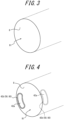
- FIG. 3 is a diagram illustrating a hollowed out hole 91 when the entirety of the covered communication device 40 is hollowed out by the hollowing out method illustrated in FIG. 2 .
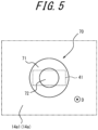
- FIG. 4 is a diagram illustrating a hollowed out hole 91 when only a part of the covered communication device 40 is hollowed out by the hollowing out method illustrated in FIG. 2 .
- the distinction portion 60 can be distinguished from a portion located around the covering body 42, of the tire body 10, in a cross-sectional view in a plane passing through the covered communication device 40 (see FIG. 1 ).
- the distinction portion 60 of the covering body 42 is configured to be distinguishable from the side rubber 8 located around the covering body 42, of the tire body 10, in the above cross-sectional view (see FIG. 1 ).
- "distinguishable" means to be capable of being distinguished through vision.
- the distinction portion 60 of this embodiment is the covering outer surface layer 42b, as the covering different-color layer 50.
- the covering outer surface layer 42b has a different hue from the surrounding side rubber 8, as described above.
- Such a covering outer surface layer 42b, as the covering different-color layer 50 is distinguishable from the surrounding side rubber 8 in the cross-sectional view in the plane passing through the covered communication device 40 (see FIG. 1 ).
- a part of the tire 1 can be hollowed out, using a cylindrical hollowing out member 90, in a tire wall thickness direction D into a cylindrical shape.
- the covering outer surface layer 42b, as the covering different-color layer 50 is not exposed on an inner surface of the hollowed out hole 91 formed by the hollowing out member 90. In other words, this indicates that the cylindrical hollowing out member 90 has hollowed out a part of the tire 1 without intersecting the covering outer surface layer 42b, as the covering different-color layer 50.
- the covering outer surface layer 42b as the covering different-color layer 50, is exposed on the inner surface of the hollowed out hole 91 formed by the hollowing out member 90.
- the distinction portion 60 in this embodiment, the covering different-color layer 50 as an example of the distinction portion 60
- the communication device 41 embedded in the tire 1 is removed by hollowing out the tire 1, it becomes easier to confirm whether the entirety of the communication device 41 is included in the hollowed out portion.
- the distinction portion 60 of this embodiment is the covering different-color layer 50 having the different hue from the portion located around the covering body 42 (side rubber 8 in this embodiment), of the tire body 10, as described above, but is not limited to this configuration.
- the distinction portion 60 may have, for example, a different brightness, saturation, gloss, or the like from the portion located around the covering body 42 (side rubber 8 in this embodiment), of the tire body 10.
- the distinction portion 60 is preferably a covering different-color layer 50 having at least a different hue from the portion located around the covering body 42 (side rubber 8 in this embodiment), of the tire body 10. By differing the hue, the distinction power of the distinction portion 60 can be enhanced.
- the covering different-color layer 50 is the covering outer surface layer 42b laminated on the outer surface of the covering rubber 42a that covers the periphery of the communication device 41.
- the layer thickness of the covering outer surface layer 42b is smaller than that of the covering rubber 42a.
- the covering different-color layer 50 may be provided in the covering rubber 42a. This detail will be described below (see FIG. 8 ).
- the covering outer surface layer 42b preferably contains the phosphorescent material.
- the distinction portion 60 preferably contains the phosphorescent material. This can realize the distinction portion 60 that emits light in a dark environment, resulting in an increase in the distinguishability of the distinction portion 60 in the dark environment.
- a part of the covering body 42 of the covered communication device 40 of this embodiment is exposed outside the tire body 10. More specifically, in this embodiment, a part of the distinction portion 60 of the covering body 42 is exposed outside the tire body 10.
- the exposure of the distinction portion 60 outside the tire body 10 allows to share the distinction portion 60 as a label area that enables the position of the communication device 41 to be distinguished from outside the tire 1.
- a portion of the covering body 42 that is exposed outside the tire body 10 is hereinafter described as "exposed portion 43".
- An exposed surface, which is a surface of the exposed portion 43 of the covering body 42 is constituted of the covering outer surface layer 42b, as the covering different-color layer 50.
- the exposed surface, which is the surface of the exposed portion 43 has a different hue from an outer surface located around the exposed portion 43, of the outer surface of the tire body 10, and constitutes a label area 70 that can be distinguished from outside the tire 1.
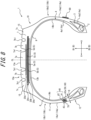
- FIGS. 5 and 6 illustrate front views of the label area 70.
- FIG. 6 is a side view of the tire 1 viewed from the side of the first side portion 10b1.
- the position of the communication device 41 is indicated by dashed lines.
- the label area 70 and the communication device 41 are disposed at the same position in the tire radial direction B.
- “the label area 70 and the communication device 41 are disposed at the same position in the tire radial direction B” means that there is at least one virtual circle L1 around the central axis O of the tire 1 that passes through the label area 70 and the communication device 41 in the side view of the tire 1 (see FIG. 6 ).
- it is not limited to a case in which the extension areas of the respective label area 70 and communication device 41 in the tire radial direction B are completely coincident.
- the label area 70 and the communication device 41 are disposed at the same position in the tire circumferential direction C.
- “the label area 70 and the communication device 41 are disposed at the same position in the tire circumferential direction C” means that, in the side view of the tire 1 (see FIG. 6 ), there is at least one virtual straight line L2 that passes through the central axis O of the tire 1 and passes through the label area 70 and the communication device 41 on one side with respect to the central axis O.
- L2 virtual straight line L2 that passes through the central axis O of the tire 1 and passes through the label area 70 and the communication device 41 on one side with respect to the central axis O.
- the label area 70 and the communication device 41 of this embodiment overlap in the tire wall thickness direction D.
- the communication device 41 of this embodiment overlaps with the label area 70 in the tire wall thickness direction D in its entire extension areas in the tire radial direction B and in the tire circumferential direction C.
- the entire communication device 41 of this embodiment overlaps with the label area 70 in the tire wall thickness direction D.
- only a part of the communication device 41 may overlap with the label area 70 in the tire wall thickness direction D.
- the entire label area 70 may overlap with the communication device 41 in the tire wall thickness direction D.
- the contour of the label area 70 may coincide with the contour of the communication device 41 in the tire wall thickness direction D.
- the entire label area 70 may overlap with the entire communication device 41 in the tire wall thickness direction D.
- the label area 70 of this embodiment is disposed in such a position that at least a part of the label area 70 overlaps with the communication device 41 in the tire wall thickness direction D. Therefore, the position of the communication device 41 can be identified by identifying the label area 70 from outside the tire 1.
- the hue of the label area 70 may differ, for example, according to the depth of embedment of the communication device 41 in the tire wall thickness direction D.
- a yellow label area 70 indicates a depth of 1 mm or more and less than 5 mm from the outer surface of the tire 1
- a blue label area 70 indicates a depth of 5 mm or more and less than 15 mm from the outer surface of the tire 1, and the like.
- the outer shape of the label area 70 may be used to indicate the depth of embedment of the communication device 41 in the tire wall thickness direction D.
- the label area 70 of this embodiment is a part of the covering outer surface layer 42b of the covering body 42. Therefore, in this embodiment, the hue of the label area 70 described above is the same as the hue of the covering outer surface layer 42b, as the covering different-color layer 50. However, of the covering outer surface layer 42b, only the label area 70 may have a different hue.
- the label area 70 of this embodiment may include a light emission area 71.
- the light emission area 71 may be, for example, a phosphorescent area that emits stored light.
- the provision of the light emission area 71 in the label area 70 allows the label area 70 to be easily identified from outside the tire 1 in a dark environment, such as at night or in a dark place. Therefore, the position of the communication device 41 can be easily identified in the dark environment.
- the light emission area 71 of the label area 70 is not particularly limited as long as the light emission area 71 is an area that emits light to the outside.
- the light emission area 71 may be composed of, for example, phosphorescent paint containing a phosphorescent material as described above.
- the label area 70 may include a non-light emission area 72 surrounded by the light emission area 71.
- the provision of such a non-light emission area 72 emphasizes the contrast between the light emission area 71 and the non-light emission area 72 in a dark environment. Therefore, the visibility of the label area 70 in the dark environment can be enhanced.
- the entire circumference of the non-light emission area 72 is surrounded by the light emission area 71 in the front view of the label area 70 (see FIGS. 5 and 6 ). More specifically, the light emission area 71 of the label area 70 of this embodiment is annular in shape in the front view of the label area 70 (see FIGS. 5 and 6 ). The non-light emission area 72 is provided inside the annular light emission area 71 in the front view of the label area 70 (see FIGS. 5 and 6 ). However, the configuration of the light emission area 71 and the non-light emission area 72 of the label area 70 is not limited to this.
- the non-light emission area 72 of the label area 70 can be identified in a dark environment, there may be a position at which no light emission area 71 is provided around the non-light emission area 72.
- Such an aspect includes, for example, a non-light emission area 72 surrounded by an approximately C-shaped light emission area 71 in the front view of the label area 70 (see FIGS. 5 and 6 ).
- the entire circumference of the non-light emission area 72 is preferably surrounded by the light emission area 71 in the front view of the label area 70 (see FIGS. 5 and 6 ). This can further emphasize the contrast between the light emission area 71 and the non-light emission area 72 in a dark environment.
- the non-light emission area 72 may have a different color from the light emission area 71.
- the "different color” means not only that at least one of hue, brightness, or saturation is different, but also that there is a difference that can be visually grasped, such as a difference in gloss. This can enhance the distinguishability of each of the light emission area 71 and the non-light emission area 72 in a bright environment.
- the non-light emission area 72 may be provided on a fine uneven surface.
- the fine uneven surface may have, for example, a base surface and a plurality of ridges with a height of 0.1 to 1.0 mm that is arranged in parallel on the base surface.
- the distance between the tops of two adjacent ridges is preferably 0.3 to 1.5 mm, for example.
- the exposed portion 43 of this embodiment protrudes outside from the outer surface of the tire body 10, but is not limited to this configuration.
- the exposed surface, which is a surface of the exposed portion 43 of this embodiment is a convex surface, but is not limited to this configuration.
- the exposed surface, which is a surface of the exposed portion 43 may be approximately flush with the outer surface of the tire body 10.
- the exposed surface, which is a surface of the exposed portion 43 is preferably the convex surface. This prevents a reduction in the visibility of the label area 70 from the outside, for example, prevents the label area 70 covered with mud or the like from being difficult to see from the outside.
- the label area 70 of this embodiment is provided on a first side outer surface 14a1, which is an outer surface of the first side portion 10b1, but as illustrated in FIG. 1 , another label area 80 may be provided on a second side outer surface 14a2, which is an outer surface of the second side portion 10b2.
- the other label area 80 may be disposed, for example, at the same position as the communication device 41 in the tire circumferential direction C. This makes it possible to identify the position of the communication device 41 in the tire circumferential direction C even from the side of the second side portion 10b2, in contrast to the case of providing only the label area 70.
- the position of the communication device 41 can be narrowed down based on the other label area 80 on the second side portion 10b2.
- the position of the communication device 41 can be easily identified regardless of the orientation of the first side portion 10b1 of the tire body 10 mounted on the vehicle.
- the other label area 80 provided on the outer surface of the second side portion 10b2 may include a light emission area, as with the label area 70 described above. This can enhance visibility from the surroundings in a dark environment.
- the other label area 80 provided on the outer surface of the second side portion 10b2 preferably has a color or shape that can be distinguished from the surroundings. Therefore, it is possible to enhance visibility from the surroundings in a bright environment.
- FIG. 7 is a cross-sectional view of the tire 100 in the tire width direction.
- the tire 100 of this embodiment differs in configuration from the tire 1 (see FIG. 1 ) described above in that the entirety of the covered communication device 40 is completely embedded within the tire body 10. Therefore, this difference will be mainly described here, and a description of the configuration common to the tire 1 of the first embodiment is omitted.
- the covered communication device 40 of this embodiment is not exposed outside the tire body 10. Even in such a case, as in the first embodiment, when the communication device 41 embedded in the tire 100 is removed by hollowing out the tire 100, it is possible to confirm, using the distinction portion 60, whether the entirety of the communication device 41 is included in a hollowed out portion, by performing the hollowing out method as illustrated in FIG. 2 .
- the entirety of the covered communication device 40 is embedded in the tire body 10, so there is no label area 70 (see FIG. 1 ), as illustrated in the first embodiment, on the first side outer surface 14a1 of the first side portion 10b1 of the tire body 10. Therefore, to remove the communication device 41 from the tire 1, for example, a position on the first side outer surface 14a1 that overlaps with the communication device 41 in the tire wall thickness direction D may be estimated using a device, such as a reader/writer, that can communicate with the communication device 41. However, for the purpose of making it easier to identify the position of the communication device 41 from outside the tire 1, a separate label area that indicates the position of overlap with the communication device 41 in the tire wall thickness direction D is preferably provided on the first side outer surface 14a1.
- FIG. 8 is a cross-sectional view of the tire 200 in the tire width direction.
- the tire 200 of this embodiment differs in the configuration of the covering body 42 from the tire 1 (see FIG. 1 ) described above, and the other configuration is common. Therefore, the above difference will be mainly described here, and a description of the configuration common to the tire 1 of the first embodiment is omitted.
- the covering body 42 of this embodiment has the covering rubber 42a that covers the periphery of the communication device 41.
- the covering different-color layer 50, as the distinction portion 60, is provided in the covering rubber 42a.
- the covering different-color layer 50 may be, for example, a part of the covering rubber 42a or the entirety of the covering rubber 42a.
- the covering different-color layer 50 may be provided only at some position of the covering rubber 42a in a thickness direction, or may be provided in the covering rubber 42a in the entire thickness direction.
- the covering different-color layer 50 of this embodiment is constituted of the entirety of the covering rubber 42a.
- providing the covering different-color layer 50, as the distinction portion 60, in the covering rubber 42a makes it easier to form the covering different-color layer 50, as the distinction portion 60, thicker as compared to the configuration of providing the covering different-color layer 50 in the covering outer surface layer 42b (see FIG. 1 ), as in the first embodiment. Therefore, when the covering different-color layer 50, as the distinction portion 60, is exposed in the hollowed out hole 91 (see FIGS. 3 and 4 ), the exposed area of the covering different-color layer 50 can be increased. As a result, the distinguishability of the distinction portion 60 on the inner surface of the hollowed out hole 91 formed in the tire 1 can be enhanced.
- the covering different-color layer 50 provided on the covering rubber 42a may be, for example, a rubber composition that is colored by mixing pigment other than carbon black. Therefore, when the entirety of the covering rubber 42a constitutes the covering different-color layer 50, the entire rubber composition constituting the covering rubber 42a may be colored by mixing pigment other than carbon black. When only a part of the covering rubber 42a constitutes the covering different-color layer 50, for example, two layers of a black rubber composition that sandwich one layer of a rubber composition colored by mixing pigment other than carbon black therebetween may be vulcanized.
- the present disclosure relates to a tire.
Landscapes
- Engineering & Computer Science (AREA)
- Mechanical Engineering (AREA)
- Tires In General (AREA)
Abstract
Description
- The present disclosure relates to a tire.
- Tires with communication devices embedded within are known. Patent Literature (PTL) 1 discloses this type of tire.
- PTL 1:
JP 2004-148953 A - In the cases of recycling tires in which communication devices are embedded, the communication devices are preferably removed and separated from the tires. When the tires are recycled, the inclusion of resin used in the communication devices may, for example, degrade the quality of recycled rubber. Also, when the tires are recycled, the inclusion of various types of metals used in the communication devices may, for example, require time and effort to separate steel cords of the tires.
- It would be helpful to provide a tire in which, when a communication device embedded in the tire is removed by hollowing out the tire, it is easy to confirm whether the entirety of the communication device is included in a hollowed out portion.
- A tire, as a first aspect of the present disclosure, includes a tire body and a covered communication device at least a part of which is embedded in the tire body. The covered communication device includes a communication device and a covering body that covers the periphery of the communication device. The covering body includes a distinction portion that is distinguishable from a portion located around the covering body, of the tire body, in a cross-sectional view in a plane passing through the covered communication device.
- According to the present disclosure, it is possible to provide a tire in which, when a communication device embedded in the tire is removed by hollowing out the tire, it is easy to confirm whether the entirety of the communication device is included in a hollowed out portion.
- In the accompanying drawings:
-
FIG. 1 is a cross-sectional view of a tire, as an embodiment of the present disclosure, in a tire width direction; -
FIG. 2 is a diagram illustrating an example of a hollowing out method of a communication device illustrated inFIG. 1 ; -
FIG. 3 is a diagram illustrating a hollowed out hole when the entirety of a covered communication device is hollowed out by the hollowing out method illustrated inFIG. 2 ; -
FIG. 4 is a diagram illustrating a hollowed out hole when only a part of the covered communication device is hollowed out by the hollowing out method illustrated inFIG. 2 ; -
FIG. 5 is a front view of a label area illustrated inFIG. 1 ; -
FIG. 6 is a side view of the tire illustrated inFIG. 1 , viewed from the side of a first side portion; -
FIG. 7 is a cross-sectional view of a tire, as an embodiment of the present disclosure, in the tire width direction; and -
FIG. 8 is a cross-sectional view of a tire, as an embodiment of the present disclosure, in the tire width direction. - Embodiments of a tire according to the present disclosure will be exemplarily described below with reference to the drawings. In the drawings, the same reference signs denote common components. In this specification, a tire width direction refers to a direction parallel to the central axis of the tire. A tire radial direction refers to a radial direction that is orthogonal to the central axis of the tire and centered on the central axis. A tire circumferential direction refers to a direction in which the tire rotates about the central axis of the tire.
- In this specification, a "tread outer surface" means an outer circumferential surface throughout the entire circumference of the tire that is in contact with a road surface when the tire mounted on a rim and filled with a specified internal pressure is rotated under a maximum load (hereinafter also referred to as "maximum load condition"). In addition, "tread ends" mean outer ends of the tread outer surface in the tire width direction.
- In this specification, the "rim" means a standard rim (Measuring Rim in ETRTO's STANDARDS MANUAL and Design Rim in TRA's YEAR BOOK) of an applicable size conformable to industrial standards valid for regions in which tires are produced and used, as described in or to be described in JATMA YEAR BOOK of the Japan Automobile Tyre Manufacturers Association, Inc. (JATMA) in Japan, STANDARDS MANUAL of the European Tyre and Rim Technical Organisation (ETRTO) in Europe, YEAR BOOK of the Tire and Rim Association, Inc. (TRA) in the United States, or the like, but in the case of a size that is not listed in such industrial standards, a rim with a width corresponding to a bead width of the tire. The "rim" may be of a size that may be included in the above industrial standards in the future, as well as a current size. Examples of the "size that is included in the future" may be sizes listed as "FUTURE DEVELOPMENTS" in the 2013 edition of STANDARDS MANUAL of the ETRTO.
- In this specification, the "specified internal pressure" means an air pressure (maximum air pressure) corresponding to a maximum load capacity of a single wheel in an applicable size and ply rating as described in the above industrial standards such as JATMA YEAR BOOK, but in the case of a size that is not listed in the above industry standards, an air pressure (maximum air pressure) corresponding to a maximum load capacity specified for each vehicle on which the tire is mounted. In this specification, the "maximum load" means a load corresponding to the maximum load capacity of the tire of an applicable size listed in the above industrial standards, but in the case of a size that is not listed in the above industrial standards, a load corresponding to the maximum load capacity specified for each vehicle on which the tire is mounted.
- A pneumatic tire 1 (hereinafter simply referred to as "tire 1") as an embodiment of the tire according to the present disclosure will be exemplarily described below with reference to the drawings. Unless otherwise stated, the tire 1 described below is assumed to mean a tire 1 that is mounted on a rim, filled with a specified internal pressure, and in a maximum load condition. The type of tire 1 is not particularly limited, and may be, for example, a tire for trucks or buses, or a tire for passenger cars.
-
FIG. 1 is a cross-sectional view of the tire 1 in the tire width direction. As illustrated inFIG. 1 , the tire 1 includes atire body 10 and a coveredcommunication device 40. - The
tire body 10 includes atread portion 10a, a first side portion 10b1, and a second side portion 10b2. The first side portion 10b1 extends from one end of thetread portion 10a in a tire width direction A toward an inner side B2 in a tire radial direction B. The second side portion 10b2 extends from the other end of thetread portion 10a in the tire width direction A toward the inner side B2 in the tire radial direction B. Hereinafter, the first side portion 10b1 and the second side portion 10b2 are simply described as "side portions 10b" when not specifically distinguished. - The
side portions 10b each have asidewall portion 11 and abead portion 12. Thesidewall portion 11 is connected to the end of thetread portion 10a in the tire width direction A and extends toward the inner side B2 in the tire radial direction B. Thebead portion 12 is connected to an end of thesidewall portion 11 on the inner side B2 in the tire radial direction B. - More specifically, the
tire body 10 of this embodiment includesbead cores 2,bead fillers 3, acarcass 4,belts 5,tread rubber 7,side rubber 8, and aninner liner 9. However, thetire body 10 may include other components, not limited to the above components. - The
bead cores 2 and thebead fillers 3 are embedded in thebead portions 12 of theside portions 10b. Eachbead core 2 includes a bead cord that is surrounded by a rubber coating. The bead cord is formed of a steel cord. Eachbead filler 3 is made of rubber and is located on an outer side B 1 in the tire radial direction B with respect to thebead core 2. - The
carcass 4 extends toroidally between the pair ofbead portions 12, which is constituted of thebead portion 12 of the first side portion 10b1 and thebead portion 12 of the second side portion 10b2, more specifically between the pair ofbead cores 2. Specifically, thecarcass 4 of this embodiment includes acarcass ply 4a. Thecarcass ply 4a is folded from the inside to the outside in the tire width direction A around therespective bead cores 2. Thecarcass ply 4a may have a plurality of ply cords arranged parallel to each other and coating rubber that coats the plurality of ply cords. Thecarcass 4 of this embodiment includes only onecarcass ply 4a, but may include two or more carcass plies 4a. The plurality of ply cords of thecarcass ply 4a may be arranged at an angle of, for example, 75° to 90° with respect to a tire circumferential direction C. The ply cords of thecarcass ply 4a can be, for example, metal cords such as steel cords. - More specifically, the
carcass ply 4a of this embodiment has a body part 4a1 located between the pair ofbead cores 2, and folded parts 4a2 that are connected to the body part 4a1 and folded from the inside to the outside in the tire width direction A around therespective bead cores 2. The above-describedbead fillers 3 are each located between the body part 4a1 and each folded part 4a2 of thecarcass ply 4a. - The
belts 5 are embedded in thetread portion 10a. Thetire body 10 of this embodiment has four of thebelts 5 on the outer side B 1 of a crown part of thecarcass 4 in the tire radial direction B. The fourbelts 5 of this embodiment include afirst belt 5a, asecond belt 5b, athird belt 5c, and afourth belt 5d. Hereafter, thefirst belt 5a, thesecond belt 5b, thethird belt 5c, and thefourth belt 5d are simply referred to as "belts 5" when not specifically distinguished. Thefirst belt 5a is located at the most inner side B2 in the tire radial direction B, among thefirst belt 5a, thesecond belt 5b, thethird belt 5c, and thefourth belt 5d. Thefourth belt 5d is located at the most outer side B 1 in the tire radial direction B, among thefirst belt 5a, thesecond belt 5b, thethird belt 5c, and thefourth belt 5d. Thesecond belt 5b and thethird belt 5c are located between thefirst belt 5a and thefourth belt 5d in the tire radial direction B. More specifically, thethird belt 5c is located on the outer side B1 of thesecond belt 5b in the tire radial direction B. - In this embodiment, the
first belt 5a, thesecond belt 5b, thethird belt 5c, and thefourth belt 5d constitute four belt layers. Specifically, thefirst belt 5a forms afirst belt layer 20a located at the most inner side B2 in the tire radial direction B. Thefourth belt 5d forms afourth belt layer 20d located at the most outer side B 1 in the tire radial direction B. Thesecond belt 5b forms asecond belt layer 20b. Thethird belt 5c forms athird belt layer 20c. - Each
belt 5 may include a plurality of belt cords arranged in parallel to each other and coating rubber that coats the plurality of belt cords. The first to fourth belt layers 20a to 20d are inclined belt layers in which the belt cords form a predetermined angle with respect to the tire circumferential direction C. The belt cords of two belt layers adjacent in the tire radial direction B, among the first to fourth belt layers 20a to 20d, may be inclined in the same direction or in opposite directions with respect to the tire circumferential direction C. - The material of the belt cords of the
belts 5 is not particularly limited. The belt cords of thebelts 5 may be, for example, metal cords or organic fiber cords. A rubber composition used for the coating rubber of thebelts 5 is not particularly limited. - As illustrated in
FIG. 1 , thetread rubber 7 is located on the outer side B1 of the crown part of the body part 4a1 of thecarcass ply 4a and on the outer side B 1 of the first tofourth belts 5a to 5d, which constitute the first to fourth belt layers 20a to 20d, in the tire radial direction B. A treadouter surface 13a, which is an outer surface of thetread portion 10a of this embodiment, is composed of thetread rubber 7. In the treadouter surface 13a, as illustrated inFIG. 1 , there are formed two inner circumferential grooves 7a1, which zone acenter land area 7a through which a tire equatorial plane CL passes, and two outer circumferential grooves 7b1, which are located outside the inner circumferential grooves 7a1 in the tire width direction A and zoneintermediate land areas 7b each between the inner circumferential groove 7a1 and the outer circumferential groove 7b1. In the treadouter surface 13a of this embodiment,shoulder land areas 7c are zoned each between the outercircumferential groove 7b 1 and atread end 15 located outside the outercircumferential groove 7b 1 in the tire width direction A. In the treadouter surface 13a, for example, width directional grooves extending in the tire width direction A or the like may be formed. - The
side rubber 8 is disposed outside the body part 4a1 and the folded parts 4a2 of thecarcass ply 4a in the tire width direction A. Sideouter surfaces 14a, which are outer surfaces of theside portions 10b of this embodiment, are composed of theside rubber 8. Ends of theside rubber 8 on the outer side B1 in the tire radial direction B are connected to ends of the above-describedtread rubber 7 in the tire width direction A. - Thus, in this embodiment, an outer surface of the
tire body 10 includes the treadouter surface 13a and the sideouter surfaces 14a, which are connected to the treadouter surface 13a. - The
inner liner 9 covers a tire inner surface side of the body part 4a1 of thecarcass ply 4a, and constitutes an inner surface of thetire body 10. The inner surface of thetire body 10 includes a treadinner surface 13b, which is an inner surface of thetread portion 10a, and sideinner surfaces 14b, which are inner surfaces of theside portions 10b. Theinner liner 9 is laminated on the tire inner surface side of the body part 4a1 of thecarcass ply 4a. Theinner liner 9 may be formed of, for example, butyl rubber with low air permeability. - As illustrated in
FIG. 1 , the coveredcommunication device 40 has acommunication device 41 and a coveringbody 42. The coveringbody 42 covers the periphery of thecommunication device 41. As illustrated inFIG. 1 , the coveredcommunication device 40 is embedded in thetire body 10. Specifically, a part of the coveredcommunication device 40 of this embodiment is embedded in thetire body 10. Another part of the coveredcommunication device 40 of this embodiment is exposed from thetire body 10. More specifically, in this embodiment, only a part of the coveringbody 42 of the coveredcommunication device 40 is exposed from the outer surface of thetire body 10. Thus, only a part of the coveredcommunication device 40 of this embodiment is embedded in thetire body 10. However, not limited to this configuration, the entirety of the coveredcommunication device 40 may be embedded in thetire body 10. - As illustrated in
FIG. 1 , the coveredcommunication device 40 of this embodiment is embedded in theside portion 10b of thetire body 10. More specifically, the coveredcommunication device 40 of this embodiment is embedded in the first side portion 10b1 of thetire body 10. The coveredcommunication device 40 of this embodiment is located, in the first side portion 10b1, outside the body part 4a1 of thecarcass 4 in the tire width direction A. However, the coveredcommunication device 40 may be embedded in another location of the first side portion 10b1. - Furthermore, the covered
communication device 40 may be embedded in another location than the first side portion 10b1. The coveredcommunication device 40 may be embedded in, for example, the second side portion 10b2 of thetire body 10. The coveredcommunication device 40 may also be embedded in thetread portion 10a of thetire body 10. - The configuration of the
communication device 41 of the coveredcommunication device 40 is not particularly limited as long as thecommunication device 41 is configured to be able to wirelessly communicate with a predetermined device outside the tire 1. An example of thecommunication device 41 is an RF tag. The RF tag, as thecommunication device 41, can wirelessly communicate with a reader/writer located outside the tire 1. The RF tag may be, for example, a passive RF tag that is operated by electric power supplied from the reader/writer located outside the tire 1. Specifically, the RF tag, as thecommunication device 41, can receive, at an antenna of the RF tag, information transmitted from an antenna of the reader/writer in the form of a radio wave or a magnetic field. Due to rectification (in the case of the radio wave) or resonance (in the case of the magnetic field), electric power is generated at the antenna of the RF tag, and a memory and a controller of the RF tag perform predetermined operations. The controller of the RF tag can, for example, read out information from the memory of the RF tag and transmit the information (back) to the reader/writer from the antenna in the form of a radio wave or a magnetic field. The antenna of the reader/writer receives the radio wave or the magnetic field from the RF tag. A controller of the reader/writer retrieves the received information to acquire the information stored in the memory of the RF tag. The above-described memory and controller of the RF tag may be configured, for example, in an integrated circuit (IC chip) including a non-volatile memory. - As described above, the covering
body 42 covers the periphery of thecommunication device 41. The coveringbody 42 of this embodiment includes coveringrubber 42a, which covers the periphery of thecommunication device 41, and a covering outer surface layer 42b, which covers the periphery of the coveringrubber 42a. - It is known that the RF tag, as the
communication device 41, is affected by the physical properties (dielectric constant, magnetic permeability, resistivity, and the like) of surrounding metals and rubber when installed in thetire body 10, resulting in the shortening of communication distance and the generation of noise. In order to prevent the shortening of communication distance and the generation of noise, thecommunication device 41 is preferably covered with a rubber composition with a low dielectric constant. Therefore, thecommunication device 41 of this embodiment is covered with the coveringrubber 42a composed of a rubber composition with a low dielectric constant. - A rubber component of the rubber composition constituting the covering
rubber 42a may be, for example, one normally used in thetread rubber 7, theside rubber 8, and the like of thetire body 10. The rubber component of the coveringrubber 42a may be, for example, natural rubber, polyisoprene rubber, polybutadiene rubber, ethylene-propylene rubber, butyl rubber, or the like. The dielectric constant of the rubber composition constituting the coveringrubber 42a may be achieved, for example, by adjusting the amount of carbon black or silica. - The covering outer surface layer 42b is, for example, a covering different-color layer 50 having a different hue from the
side rubber 8, which is a portion located around the covering outer surface layer 42b, of thetire body 10. Theside rubber 8 is usually black in color due to the blend of carbon black. Therefore, the hue of the covering outer surface layer 42b of this embodiment is other than black. By providing such a covering different-color layer 50, when thecommunication device 41 embedded in the tire 1 is removed by hollowing out the tire 1, it becomes easier to confirm whether the entirety of thecommunication device 41 is included in a hollowed out portion. This detail will be described below (seeFIGS. 2 to 4 ). - The covering outer surface layer 42b may have the same hue as the covering
rubber 42a described above, or may have a different hue. However, when carbon black is blended into the rubber composition constituting the coveringrubber 42a to achieve a low dielectric constant, the hue of the coveringrubber 42a is black, which is the same as the hue of theside rubber 8. In such a case, the hue of the covering outer surface layer 42b is preferably different from that of theside rubber 8 and the coveringrubber 42a. - The covering outer surface layer 42b, as the covering different-color layer 50, may be composed of, for example, paint containing pigment. In other words, the covering outer surface layer 42b, as the covering different-color layer 50, may be coloring paint laminated to an outer surface of the covering
rubber 42a. The covering outer surface layer 42b, as the covering different-color layer 50, may be, for example, a rubber composition colored with pigment other than carbon black. In other words, the covering outer surface layer 42b, as the covering different-color layer 50, may be colored rubber that is laminated to the outer surface of the coveringrubber 42a. - The covering outer surface layer 42b, as the covering different-color layer 50, preferably contains a phosphorescent material. The covering outer surface layer 42b containing the phosphorescent material may be composed of, for example, paint containing the phosphorescent material in addition to pigment. The covering outer surface layer 42b containing the phosphorescent material may be composed of, for example, a rubber composition containing the phosphorescent material in addition to pigment other than carbon black.
- The phosphorescent material is not particularly limited, and any known phosphorescent material may be used. Examples of the phosphorescent material include, for example, compositions: SrAl2O4: Eu, Dy; Sr4Al14O25: Eu, Dy; SrAl2O4: Eu, Dy + Sr4Al14O25: Eu, Dy; Sr4Al14O25: Eu, Dy + CaAl2O4: Eu, Nd; CaAl2O4: Eu, Nd; ZnS: Cu, Mn, Co; ZnS: Cu; and the like.
- Next, a distinction portion 60 of the covering
body 42 will be described with reference toFIGS. 1 to 4 .FIG. 2 is an explanation diagram that explains an example of a hollowing out method of thecommunication device 41.FIG. 3 is a diagram illustrating a hollowed outhole 91 when the entirety of the coveredcommunication device 40 is hollowed out by the hollowing out method illustrated inFIG. 2 .FIG. 4 is a diagram illustrating a hollowed outhole 91 when only a part of the coveredcommunication device 40 is hollowed out by the hollowing out method illustrated inFIG. 2 . - The distinction portion 60 can be distinguished from a portion located around the covering
body 42, of thetire body 10, in a cross-sectional view in a plane passing through the covered communication device 40 (seeFIG. 1 ). In other words, in this embodiment, the distinction portion 60 of the coveringbody 42 is configured to be distinguishable from theside rubber 8 located around the coveringbody 42, of thetire body 10, in the above cross-sectional view (seeFIG. 1 ). Here, "distinguishable" means to be capable of being distinguished through vision. More specifically, the distinction portion 60 of this embodiment is the covering outer surface layer 42b, as the covering different-color layer 50. The covering outer surface layer 42b has a different hue from the surroundingside rubber 8, as described above. Such a covering outer surface layer 42b, as the covering different-color layer 50, is distinguishable from the surroundingside rubber 8 in the cross-sectional view in the plane passing through the covered communication device 40 (seeFIG. 1 ). - In the hollowing out method illustrated in
FIG. 2 , a part of the tire 1 can be hollowed out, using a cylindrical hollowing outmember 90, in a tire wall thickness direction D into a cylindrical shape. In the example illustrated inFIG. 3 , the covering outer surface layer 42b, as the covering different-color layer 50, is not exposed on an inner surface of the hollowed outhole 91 formed by the hollowing outmember 90. In other words, this indicates that the cylindrical hollowing outmember 90 has hollowed out a part of the tire 1 without intersecting the covering outer surface layer 42b, as the covering different-color layer 50. By confirming that the covering outer surface layer 42b, as the covering different-color layer 50, is not exposed on the inner surface of the hollowed outhole 91, it can be confirmed that the entirety of the coveredcommunication device 40 including the entirety of thecommunication device 41 has been hollowed out. - In the example illustrated in
FIG. 4 , the covering outer surface layer 42b, as the covering different-color layer 50, is exposed on the inner surface of the hollowed outhole 91 formed by the hollowing outmember 90. In other words, this indicates that the cylindrical hollowing outmember 90 has hollowed out a part of the tire 1 in such a manner as to intersect the covering outer surface layer 42b, as the covering different-color layer 50. By confirming that the covering outer surface layer 42b, as the covering different-color layer 50, is exposed on the inner surface of the hollowed outhole 91, it can be confirmed that not the entirety of the coveredcommunication device 40 including the entirety of thecommunication device 41 has been hollowed out. In other words, it is possible to grasp the possibility that a part of thecommunication device 41 remains without being hollowed out. - Thus, by providing the distinction portion 60 (in this embodiment, the covering different-color layer 50 as an example of the distinction portion 60), when the
communication device 41 embedded in the tire 1 is removed by hollowing out the tire 1, it becomes easier to confirm whether the entirety of thecommunication device 41 is included in the hollowed out portion. - The distinction portion 60 of this embodiment is the covering different-color layer 50 having the different hue from the portion located around the covering body 42 (
side rubber 8 in this embodiment), of thetire body 10, as described above, but is not limited to this configuration. The distinction portion 60 may have, for example, a different brightness, saturation, gloss, or the like from the portion located around the covering body 42 (side rubber 8 in this embodiment), of thetire body 10. However, as in this embodiment, the distinction portion 60 is preferably a covering different-color layer 50 having at least a different hue from the portion located around the covering body 42 (side rubber 8 in this embodiment), of thetire body 10. By differing the hue, the distinction power of the distinction portion 60 can be enhanced. - The covering different-color layer 50, as the distinction portion 60, of this embodiment is the covering outer surface layer 42b laminated on the outer surface of the covering
rubber 42a that covers the periphery of thecommunication device 41. The layer thickness of the covering outer surface layer 42b is smaller than that of the coveringrubber 42a. With this configuration, the coveringrubber 42a, which is aimed at preventing the shortening of communication distance and the generation of noise, and the covering outer surface layer 42b, which is aimed at improving distinguishability, can be configured in a functionally separated manner. In other words, there is no need to make a single layer that shares the functions of preventing the shortening of communication distance and the generation of noise and improving distinguishability, so the degree of freedom in the design of the coveringbody 42 can be increased. - However, the covering different-color layer 50, as the distinction portion 60, may be provided in the covering
rubber 42a. This detail will be described below (seeFIG. 8 ). - As described above, the covering outer surface layer 42b, as the covering different-color layer 50, preferably contains the phosphorescent material. In other words, the distinction portion 60 preferably contains the phosphorescent material. This can realize the distinction portion 60 that emits light in a dark environment, resulting in an increase in the distinguishability of the distinction portion 60 in the dark environment.
- As illustrated in
FIG. 1 , a part of the coveringbody 42 of the coveredcommunication device 40 of this embodiment is exposed outside thetire body 10. More specifically, in this embodiment, a part of the distinction portion 60 of the coveringbody 42 is exposed outside thetire body 10. The exposure of the distinction portion 60 outside thetire body 10 allows to share the distinction portion 60 as a label area that enables the position of thecommunication device 41 to be distinguished from outside the tire 1. In this embodiment, a portion of the coveringbody 42 that is exposed outside thetire body 10 is hereinafter described as "exposedportion 43". An exposed surface, which is a surface of the exposedportion 43 of the coveringbody 42, is constituted of the covering outer surface layer 42b, as the covering different-color layer 50. In other words, the exposed surface, which is the surface of the exposedportion 43, has a different hue from an outer surface located around the exposedportion 43, of the outer surface of thetire body 10, and constitutes alabel area 70 that can be distinguished from outside the tire 1. -
FIGS. 5 and6 illustrate front views of thelabel area 70. In particular,FIG. 6 is a side view of the tire 1 viewed from the side of the first side portion 10b1. InFIGS. 5 and6 , the position of thecommunication device 41 is indicated by dashed lines. As illustrated inFIG. 6 , in this embodiment, thelabel area 70 and thecommunication device 41 are disposed at the same position in the tire radial direction B. Here, "thelabel area 70 and thecommunication device 41 are disposed at the same position in the tire radial direction B" means that there is at least one virtual circle L1 around the central axis O of the tire 1 that passes through thelabel area 70 and thecommunication device 41 in the side view of the tire 1 (seeFIG. 6 ). In other words, it is not limited to a case in which the extension areas of therespective label area 70 andcommunication device 41 in the tire radial direction B are completely coincident. - As illustrated in
FIG. 6 , in this embodiment, thelabel area 70 and thecommunication device 41 are disposed at the same position in the tire circumferential direction C. Here, "thelabel area 70 and thecommunication device 41 are disposed at the same position in the tire circumferential direction C" means that, in the side view of the tire 1 (seeFIG. 6 ), there is at least one virtual straight line L2 that passes through the central axis O of the tire 1 and passes through thelabel area 70 and thecommunication device 41 on one side with respect to the central axis O. In other words, it is not limited to a case in which the extension areas of therespective label area 70 andcommunication device 41 in the tire circumferential direction C are completely coincident. - In other words, the
label area 70 and thecommunication device 41 of this embodiment overlap in the tire wall thickness direction D. Thecommunication device 41 of this embodiment overlaps with thelabel area 70 in the tire wall thickness direction D in its entire extension areas in the tire radial direction B and in the tire circumferential direction C. In other words, theentire communication device 41 of this embodiment overlaps with thelabel area 70 in the tire wall thickness direction D. However, only a part of thecommunication device 41 may overlap with thelabel area 70 in the tire wall thickness direction D. Theentire label area 70 may overlap with thecommunication device 41 in the tire wall thickness direction D. Furthermore, the contour of thelabel area 70 may coincide with the contour of thecommunication device 41 in the tire wall thickness direction D. In other words, theentire label area 70 may overlap with theentire communication device 41 in the tire wall thickness direction D. - Thus, the
label area 70 of this embodiment is disposed in such a position that at least a part of thelabel area 70 overlaps with thecommunication device 41 in the tire wall thickness direction D. Therefore, the position of thecommunication device 41 can be identified by identifying thelabel area 70 from outside the tire 1. - The hue of the
label area 70 may differ, for example, according to the depth of embedment of thecommunication device 41 in the tire wall thickness direction D. For example, it is conceivable that ayellow label area 70 indicates a depth of 1 mm or more and less than 5 mm from the outer surface of the tire 1, ablue label area 70 indicates a depth of 5 mm or more and less than 15 mm from the outer surface of the tire 1, and the like. However, not limited to the hue of thelabel area 70, for example, the outer shape of thelabel area 70 may be used to indicate the depth of embedment of thecommunication device 41 in the tire wall thickness direction D. Thelabel area 70 of this embodiment is a part of the covering outer surface layer 42b of the coveringbody 42. Therefore, in this embodiment, the hue of thelabel area 70 described above is the same as the hue of the covering outer surface layer 42b, as the covering different-color layer 50. However, of the covering outer surface layer 42b, only thelabel area 70 may have a different hue. - As illustrated in
FIGS. 5 and6 , thelabel area 70 of this embodiment may include alight emission area 71. Thelight emission area 71 may be, for example, a phosphorescent area that emits stored light. The provision of thelight emission area 71 in thelabel area 70 allows thelabel area 70 to be easily identified from outside the tire 1 in a dark environment, such as at night or in a dark place. Therefore, the position of thecommunication device 41 can be easily identified in the dark environment. Thelight emission area 71 of thelabel area 70 is not particularly limited as long as thelight emission area 71 is an area that emits light to the outside. Thelight emission area 71 may be composed of, for example, phosphorescent paint containing a phosphorescent material as described above. - As illustrated in
FIGS. 5 and6 , thelabel area 70 may include anon-light emission area 72 surrounded by thelight emission area 71. The provision of such anon-light emission area 72 emphasizes the contrast between thelight emission area 71 and thenon-light emission area 72 in a dark environment. Therefore, the visibility of thelabel area 70 in the dark environment can be enhanced. - In this embodiment, the entire circumference of the
non-light emission area 72 is surrounded by thelight emission area 71 in the front view of the label area 70 (seeFIGS. 5 and6 ). More specifically, thelight emission area 71 of thelabel area 70 of this embodiment is annular in shape in the front view of the label area 70 (seeFIGS. 5 and6 ). Thenon-light emission area 72 is provided inside the annularlight emission area 71 in the front view of the label area 70 (seeFIGS. 5 and6 ). However, the configuration of thelight emission area 71 and thenon-light emission area 72 of thelabel area 70 is not limited to this. As long as thenon-light emission area 72 of thelabel area 70 can be identified in a dark environment, there may be a position at which nolight emission area 71 is provided around thenon-light emission area 72. Such an aspect includes, for example, anon-light emission area 72 surrounded by an approximately C-shapedlight emission area 71 in the front view of the label area 70 (seeFIGS. 5 and6 ). However, as in this embodiment, the entire circumference of thenon-light emission area 72 is preferably surrounded by thelight emission area 71 in the front view of the label area 70 (seeFIGS. 5 and6 ). This can further emphasize the contrast between thelight emission area 71 and thenon-light emission area 72 in a dark environment. - The
non-light emission area 72 may have a different color from thelight emission area 71. Here, the "different color" means not only that at least one of hue, brightness, or saturation is different, but also that there is a difference that can be visually grasped, such as a difference in gloss. This can enhance the distinguishability of each of thelight emission area 71 and thenon-light emission area 72 in a bright environment. - The
non-light emission area 72 may be provided on a fine uneven surface. The fine uneven surface may have, for example, a base surface and a plurality of ridges with a height of 0.1 to 1.0 mm that is arranged in parallel on the base surface. The distance between the tops of two adjacent ridges is preferably 0.3 to 1.5 mm, for example. The provision of thenon-light emission area 72 on such a fine uneven surface can control the reflection of light from thenon-light emission area 72 in a bright environment, and therefore can achieve a high contrast with the surroundinglight emission area 71, which reflects light. Therefore, the distinguishability of each of thelight emission area 71 and thenon-light emission area 72 can be further enhanced in the bright environment. - As illustrated in
FIG. 1 , the exposedportion 43 of this embodiment protrudes outside from the outer surface of thetire body 10, but is not limited to this configuration. In other words, the exposed surface, which is a surface of the exposedportion 43 of this embodiment, is a convex surface, but is not limited to this configuration. The exposed surface, which is a surface of the exposedportion 43, may be approximately flush with the outer surface of thetire body 10. However, as in this embodiment, the exposed surface, which is a surface of the exposedportion 43, is preferably the convex surface. This prevents a reduction in the visibility of thelabel area 70 from the outside, for example, prevents thelabel area 70 covered with mud or the like from being difficult to see from the outside. - The
label area 70 of this embodiment is provided on a first side outer surface 14a1, which is an outer surface of the first side portion 10b1, but as illustrated inFIG. 1 , anotherlabel area 80 may be provided on a second side outer surface 14a2, which is an outer surface of the second side portion 10b2. Theother label area 80 may be disposed, for example, at the same position as thecommunication device 41 in the tire circumferential direction C. This makes it possible to identify the position of thecommunication device 41 in the tire circumferential direction C even from the side of the second side portion 10b2, in contrast to the case of providing only thelabel area 70. Therefore, for example, even when the tire 1 is mounted on a vehicle with the first side portion 10b1 disposed inside the vehicle, and thelabel area 70 is not visible from outside the vehicle, the position of thecommunication device 41 can be narrowed down based on theother label area 80 on the second side portion 10b2. The position of thecommunication device 41 can be easily identified regardless of the orientation of the first side portion 10b1 of thetire body 10 mounted on the vehicle. - The
other label area 80 provided on the outer surface of the second side portion 10b2 may include a light emission area, as with thelabel area 70 described above. This can enhance visibility from the surroundings in a dark environment. Theother label area 80 provided on the outer surface of the second side portion 10b2 preferably has a color or shape that can be distinguished from the surroundings. Therefore, it is possible to enhance visibility from the surroundings in a bright environment. - Next, with reference to
FIG. 7 , a pneumatic tire 100 (hereinafter simply referred to as "tire 100") as an embodiment of the tire according to the present disclosure will be exemplarily described.FIG. 7 is a cross-sectional view of the tire 100 in the tire width direction. The tire 100 of this embodiment differs in configuration from the tire 1 (seeFIG. 1 ) described above in that the entirety of the coveredcommunication device 40 is completely embedded within thetire body 10. Therefore, this difference will be mainly described here, and a description of the configuration common to the tire 1 of the first embodiment is omitted. - As illustrated in
FIG. 7 , the coveredcommunication device 40 of this embodiment is not exposed outside thetire body 10. Even in such a case, as in the first embodiment, when thecommunication device 41 embedded in the tire 100 is removed by hollowing out the tire 100, it is possible to confirm, using the distinction portion 60, whether the entirety of thecommunication device 41 is included in a hollowed out portion, by performing the hollowing out method as illustrated inFIG. 2 . - In this embodiment, the entirety of the covered
communication device 40 is embedded in thetire body 10, so there is no label area 70 (seeFIG. 1 ), as illustrated in the first embodiment, on the first side outer surface 14a1 of the first side portion 10b1 of thetire body 10. Therefore, to remove thecommunication device 41 from the tire 1, for example, a position on the first side outer surface 14a1 that overlaps with thecommunication device 41 in the tire wall thickness direction D may be estimated using a device, such as a reader/writer, that can communicate with thecommunication device 41. However, for the purpose of making it easier to identify the position of thecommunication device 41 from outside the tire 1, a separate label area that indicates the position of overlap with thecommunication device 41 in the tire wall thickness direction D is preferably provided on the first side outer surface 14a1. - Next, with reference to
FIG. 8 , a pneumatic tire 200 (hereinafter simply referred to as "tire 200") as an embodiment of the tire according to the present disclosure will be exemplarily described.FIG. 8 is a cross-sectional view of the tire 200 in the tire width direction. The tire 200 of this embodiment differs in the configuration of the coveringbody 42 from the tire 1 (seeFIG. 1 ) described above, and the other configuration is common. Therefore, the above difference will be mainly described here, and a description of the configuration common to the tire 1 of the first embodiment is omitted. - The covering
body 42 of this embodiment has the coveringrubber 42a that covers the periphery of thecommunication device 41. The covering different-color layer 50, as the distinction portion 60, is provided in the coveringrubber 42a. - The covering different-color layer 50, as the distinction portion 60, may be, for example, a part of the covering
rubber 42a or the entirety of the coveringrubber 42a. In other words, the covering different-color layer 50, as the distinction portion 60, may be provided only at some position of the coveringrubber 42a in a thickness direction, or may be provided in the coveringrubber 42a in the entire thickness direction. As illustrated inFIG. 8 , the covering different-color layer 50 of this embodiment is constituted of the entirety of the coveringrubber 42a. - Thus, providing the covering different-color layer 50, as the distinction portion 60, in the covering
rubber 42a makes it easier to form the covering different-color layer 50, as the distinction portion 60, thicker as compared to the configuration of providing the covering different-color layer 50 in the covering outer surface layer 42b (seeFIG. 1 ), as in the first embodiment. Therefore, when the covering different-color layer 50, as the distinction portion 60, is exposed in the hollowed out hole 91 (seeFIGS. 3 and 4 ), the exposed area of the covering different-color layer 50 can be increased. As a result, the distinguishability of the distinction portion 60 on the inner surface of the hollowed outhole 91 formed in the tire 1 can be enhanced. - The covering different-color layer 50 provided on the covering
rubber 42a may be, for example, a rubber composition that is colored by mixing pigment other than carbon black. Therefore, when the entirety of the coveringrubber 42a constitutes the covering different-color layer 50, the entire rubber composition constituting the coveringrubber 42a may be colored by mixing pigment other than carbon black. When only a part of the coveringrubber 42a constitutes the covering different-color layer 50, for example, two layers of a black rubber composition that sandwich one layer of a rubber composition colored by mixing pigment other than carbon black therebetween may be vulcanized. - Even when the entirety of the covering
rubber 42a constitutes the covering different-color layer 50, as in this embodiment, thelabel area 70 can be realized by the exposed surface, which is a surface of the exposedportion 43 exposed from thetire body 10. - As in the first embodiment, the
label area 70 may include the light emission area 71 (seeFIG. 5 and the like) and the non-light emission area 72 (seeFIG. 5 and the like). In this embodiment, thelight emission area 71 can be realized, for example, by a rubber composition in which a phosphorescent material is mixed together with pigment. - The tire according to the present disclosure is not limited to the specific configuration described in the above embodiments, and various variations, modifications, and combinations are possible without departing from the scope of the claims.
- The present disclosure relates to a tire.
-
- 1, 100, 200
- tire
- 2
- bead core
- 3
- bead filler
- 4
- carcass
- 4a
- carcass ply
- 4a1
- body part
- 4a2
- folded part
- 5
- belt
- 5a - 5d
- first to fourth belts
- 7
- tread rubber
- 7a
- center land area
- 7a1
- inner circumferential groove
- 7b
- intermediate land area
- 7b1
- outer circumferential groove
- 7c
- shoulder land area
- 8
- side rubber
- 9
- inner liner
- 10
- tire body
- 10a
- tread portion
- 10b
- side portion
- 10b1
- first side portion
- 10b2
- second side portion
- 11
- sidewall portion
- 12
- bead portion
- 13a
- tread outer surface
- 13b
- tread inner surface
- 14a
- side outer surface
- 14a1
- first side outer surface
- 14a2
- second side outer surface
- 14b
- side inner surface
- 15
- tread end
- 20a - 20d
- first to fourth belt layers
- 40
- covered communication device
- 41
- communication device
- 42
- covering body
- 42a
- covering rubber
- 42b
- covering outer surface layer
- 43
- exposed portion
- 50
- covering different-color layer
- 60
- distinction portion
- 70
- label area
- 71
- light emission area
- 72
- non-light emission area
- 80
- label area
- 90
- hollowing out member
- 91
- hollowed out hole
- A
- tire width direction
- B
- tire radial direction
- B1
- outer side in tire radial direction
- B2
- inner side in tire radial direction
- C
- tire circumferential direction
- D
- tire wall thickness direction
- O
- central axis of tire
- CL
- tire equatorial plane
- L1
- virtual circle
- L2
- virtual straight line
Claims (6)
- A tire comprising:a tire body; anda covered communication device at least a part of which is embedded in the tire body,whereinthe covered communication device comprises:a communication device; anda covering body that covers a periphery of the communication device, andthe covering body comprises a distinction portion that is distinguishable from a portion located around the covering body, of the tire body, in a cross-sectional view in a plane passing through the covered communication device.
- The tire according to claim 1, whereinthe covering body comprises a covering different-color layer having a different hue from the portion located around the covering body, of the tire body, andthe distinction portion is the covering different-color layer.
- The tire according to claim 2, whereinthe covering body comprises:covering rubber that covers the periphery of the communication device; anda covering outer surface layer that covers a periphery of the covering rubber, andthe covering different-color layer is the covering outer surface layer.
- The tire according to claim 2, whereinthe covering body comprises covering rubber that covers the periphery of the communication device, andthe covering different-color layer is provided in the covering rubber.
- The tire according to any one of claims 1 to 4, wherein a part of the distinction portion of the covering body is exposed from an outer surface of the tire body.
- The tire according to any one of claims 1 to 5, wherein the distinction portion of the covering body includes a light emission area.
Applications Claiming Priority (2)
| Application Number | Priority Date | Filing Date | Title |
|---|---|---|---|
| JP2021200135A JP7701866B2 (en) | 2021-12-09 | 2021-12-09 | tire |
| PCT/JP2022/024948 WO2023105825A1 (en) | 2021-12-09 | 2022-06-22 | Tire |
Publications (2)
| Publication Number | Publication Date |
|---|---|
| EP4446136A1 true EP4446136A1 (en) | 2024-10-16 |
| EP4446136A4 EP4446136A4 (en) | 2025-03-26 |
Family
ID=86730015
Family Applications (1)
| Application Number | Title | Priority Date | Filing Date |
|---|---|---|---|
| EP22903761.9A Pending EP4446136A4 (en) | 2021-12-09 | 2022-06-22 | TIRE |
Country Status (5)
| Country | Link |
|---|---|
| US (1) | US20240416684A1 (en) |
| EP (1) | EP4446136A4 (en) |
| JP (1) | JP7701866B2 (en) |
| CN (1) | CN118234631A (en) |
| WO (1) | WO2023105825A1 (en) |
Family Cites Families (12)
| Publication number | Priority date | Publication date | Assignee | Title |
|---|---|---|---|---|
| US6807995B1 (en) * | 2000-03-21 | 2004-10-26 | The Goodyear Tire & Rubber Company | Glow-in-the-dark tire sidewalls |
| JP4501097B2 (en) * | 2001-01-12 | 2010-07-14 | 横浜ゴム株式会社 | Transponder for mounting tire and method for manufacturing tire mounted with transponder |
| JP4183032B2 (en) * | 2002-08-30 | 2008-11-19 | 横浜ゴム株式会社 | Pneumatic tire equipped with a film-like electronic device and method for attaching the film-like electronic device |
| US20040134578A1 (en) * | 2002-12-23 | 2004-07-15 | Kleckner James P. | Tire with tire tag |
| JP4482860B2 (en) * | 2003-10-29 | 2010-06-16 | 横浜ゴム株式会社 | Tire sensor pins and tires |
| JPWO2005095127A1 (en) * | 2004-03-31 | 2008-02-21 | 株式会社ブリヂストン | Wireless IC tag mounting holder and tire with wireless IC tag |
| JP4487125B2 (en) * | 2004-08-23 | 2010-06-23 | 横浜ゴム株式会社 | Pneumatic tire |
| FR2966768B1 (en) * | 2010-10-28 | 2013-09-27 | Michelin Soc Tech | METHOD FOR MANUFACTURING A TIRE COMPRISING AN ELECTRONIC ASSEMBLY |
| JP6492770B2 (en) * | 2015-02-27 | 2019-04-03 | 横浜ゴム株式会社 | Pneumatic tire |
| US10621485B2 (en) * | 2018-02-28 | 2020-04-14 | FineLine Technologies | RFID mesh label, tire having RFID mesh label integrally incorporated therein, and methods of making |
| JP7198633B2 (en) * | 2018-10-31 | 2023-01-04 | 株式会社ブリヂストン | Tire and tire manufacturing method |
| JP6686109B1 (en) * | 2018-11-26 | 2020-04-22 | Toyo Tire株式会社 | tire |
-
2021
- 2021-12-09 JP JP2021200135A patent/JP7701866B2/en active Active
-
2022
- 2022-06-22 US US18/706,835 patent/US20240416684A1/en active Pending
- 2022-06-22 WO PCT/JP2022/024948 patent/WO2023105825A1/en not_active Ceased
- 2022-06-22 CN CN202280074874.4A patent/CN118234631A/en active Pending
- 2022-06-22 EP EP22903761.9A patent/EP4446136A4/en active Pending
Also Published As
| Publication number | Publication date |
|---|---|
| JP2023085852A (en) | 2023-06-21 |
| CN118234631A (en) | 2024-06-21 |
| JP7701866B2 (en) | 2025-07-02 |
| US20240416684A1 (en) | 2024-12-19 |
| EP4446136A4 (en) | 2025-03-26 |
| WO2023105825A1 (en) | 2023-06-15 |
Similar Documents
| Publication | Publication Date | Title |
|---|---|---|
| US20220172465A1 (en) | Pneumatic Tire and Vehicle | |
| CN100560386C (en) | pneumatic tire | |
| EP4296091B1 (en) | Heavy duty tire | |
| EP4389465B1 (en) | Heavy duty tire | |
| JP6443856B2 (en) | Pneumatic tire and vehicle | |
| EP4328050B1 (en) | Tire | |
| US12017485B2 (en) | Heavy duty tire | |
| EP4446136A1 (en) | Tire | |
| EP4446134B1 (en) | Tire | |
| US12508850B2 (en) | Heavy duty tire | |
| EP4212364B1 (en) | Heavy duty pneumatic tire | |
| EP4364976B1 (en) | TIRES | |
| JP7742291B2 (en) | tire | |
| JP7732877B2 (en) | Tire-wheel assembly and wheel | |
| US20250282180A1 (en) | Heavy duty tire | |
| CN117460631B (en) | Tire with a tire body | |
| EP4523929A1 (en) | Heavy duty tire | |
| EP4438347A1 (en) | Pneumatic radial tire for passenger vehicle | |
| AU2023395090A1 (en) | Tire | |
| JP2023085864A (en) | tire | |
| JP2016097838A (en) | Pneumatic tire and vehicle | |
| JP2016094040A (en) | Pneumatic tire and vehicle |
Legal Events
| Date | Code | Title | Description |
|---|---|---|---|
| STAA | Information on the status of an ep patent application or granted ep patent |
Free format text: STATUS: THE INTERNATIONAL PUBLICATION HAS BEEN MADE |
|
| PUAI | Public reference made under article 153(3) epc to a published international application that has entered the european phase |
Free format text: ORIGINAL CODE: 0009012 |
|
| STAA | Information on the status of an ep patent application or granted ep patent |
Free format text: STATUS: REQUEST FOR EXAMINATION WAS MADE |
|
| 17P | Request for examination filed |
Effective date: 20240228 |
|
| AK | Designated contracting states |
Kind code of ref document: A1 Designated state(s): AL AT BE BG CH CY CZ DE DK EE ES FI FR GB GR HR HU IE IS IT LI LT LU LV MC MK MT NL NO PL PT RO RS SE SI SK SM TR |
|
| DAV | Request for validation of the european patent (deleted) | ||
| DAX | Request for extension of the european patent (deleted) | ||
| A4 | Supplementary search report drawn up and despatched |
Effective date: 20250226 |
|
| RIC1 | Information provided on ipc code assigned before grant |
Ipc: B60C 13/04 20060101ALI20250220BHEP Ipc: B60C 19/00 20060101AFI20250220BHEP |
|
| GRAP | Despatch of communication of intention to grant a patent |
Free format text: ORIGINAL CODE: EPIDOSNIGR1 |
|
| STAA | Information on the status of an ep patent application or granted ep patent |
Free format text: STATUS: GRANT OF PATENT IS INTENDED |
|
| RIC1 | Information provided on ipc code assigned before grant |
Ipc: B60C 19/00 20060101AFI20251127BHEP Ipc: B60C 13/04 20060101ALI20251127BHEP Ipc: B29D 30/00 20060101ALI20251127BHEP |
|
| INTG | Intention to grant announced |
Effective date: 20251222 |
|
| GRAJ | Information related to disapproval of communication of intention to grant by the applicant or resumption of examination proceedings by the epo deleted |
Free format text: ORIGINAL CODE: EPIDOSDIGR1 |
|
| STAA | Information on the status of an ep patent application or granted ep patent |
Free format text: STATUS: REQUEST FOR EXAMINATION WAS MADE |
|
| P01 | Opt-out of the competence of the unified patent court (upc) registered |
Free format text: CASE NUMBER: UPC_APP_0000369_4446136/2026 Effective date: 20260106 |
|
| GRAP | Despatch of communication of intention to grant a patent |
Free format text: ORIGINAL CODE: EPIDOSNIGR1 |
|
| STAA | Information on the status of an ep patent application or granted ep patent |
Free format text: STATUS: GRANT OF PATENT IS INTENDED |
|
| INTC | Intention to grant announced (deleted) | ||
| GRAS | Grant fee paid |
Free format text: ORIGINAL CODE: EPIDOSNIGR3 |
|
| INTG | Intention to grant announced |
Effective date: 20260305 |
|
| GRAA | (expected) grant |
Free format text: ORIGINAL CODE: 0009210 |
|
| STAA | Information on the status of an ep patent application or granted ep patent |
Free format text: STATUS: THE PATENT HAS BEEN GRANTED |