EP4446130A1 - Tire - Google Patents
Tire Download PDFInfo
- Publication number
- EP4446130A1 EP4446130A1 EP24168268.1A EP24168268A EP4446130A1 EP 4446130 A1 EP4446130 A1 EP 4446130A1 EP 24168268 A EP24168268 A EP 24168268A EP 4446130 A1 EP4446130 A1 EP 4446130A1
- Authority
- EP
- European Patent Office
- Prior art keywords
- tire
- lateral
- longitudinal hole
- hole
- land portion
- Prior art date
- Legal status (The legal status is an assumption and is not a legal conclusion. Google has not performed a legal analysis and makes no representation as to the accuracy of the status listed.)
- Granted
Links
Images


Classifications
-
- B—PERFORMING OPERATIONS; TRANSPORTING
- B60—VEHICLES IN GENERAL
- B60C—VEHICLE TYRES; TYRE INFLATION; TYRE CHANGING; CONNECTING VALVES TO INFLATABLE ELASTIC BODIES IN GENERAL; DEVICES OR ARRANGEMENTS RELATED TO TYRES
- B60C11/00—Tyre tread bands; Tread patterns; Anti-skid inserts
- B60C11/03—Tread patterns
- B60C11/032—Patterns comprising isolated recesses
-
- B—PERFORMING OPERATIONS; TRANSPORTING
- B60—VEHICLES IN GENERAL
- B60C—VEHICLE TYRES; TYRE INFLATION; TYRE CHANGING; CONNECTING VALVES TO INFLATABLE ELASTIC BODIES IN GENERAL; DEVICES OR ARRANGEMENTS RELATED TO TYRES
- B60C11/00—Tyre tread bands; Tread patterns; Anti-skid inserts
- B60C11/03—Tread patterns
- B60C11/0306—Patterns comprising block rows or discontinuous ribs
-
- B—PERFORMING OPERATIONS; TRANSPORTING
- B60—VEHICLES IN GENERAL
- B60C—VEHICLE TYRES; TYRE INFLATION; TYRE CHANGING; CONNECTING VALVES TO INFLATABLE ELASTIC BODIES IN GENERAL; DEVICES OR ARRANGEMENTS RELATED TO TYRES
- B60C11/00—Tyre tread bands; Tread patterns; Anti-skid inserts
- B60C11/03—Tread patterns
- B60C2011/0337—Tread patterns characterised by particular design features of the pattern
- B60C2011/0339—Grooves
- B60C2011/0341—Circumferential grooves
-
- B—PERFORMING OPERATIONS; TRANSPORTING
- B60—VEHICLES IN GENERAL
- B60C—VEHICLE TYRES; TYRE INFLATION; TYRE CHANGING; CONNECTING VALVES TO INFLATABLE ELASTIC BODIES IN GENERAL; DEVICES OR ARRANGEMENTS RELATED TO TYRES
- B60C11/00—Tyre tread bands; Tread patterns; Anti-skid inserts
- B60C11/03—Tread patterns
- B60C2011/0337—Tread patterns characterised by particular design features of the pattern
- B60C2011/0339—Grooves
- B60C2011/0341—Circumferential grooves
- B60C2011/0344—Circumferential grooves provided at the equatorial plane
-
- B—PERFORMING OPERATIONS; TRANSPORTING
- B60—VEHICLES IN GENERAL
- B60C—VEHICLE TYRES; TYRE INFLATION; TYRE CHANGING; CONNECTING VALVES TO INFLATABLE ELASTIC BODIES IN GENERAL; DEVICES OR ARRANGEMENTS RELATED TO TYRES
- B60C11/00—Tyre tread bands; Tread patterns; Anti-skid inserts
- B60C11/03—Tread patterns
- B60C11/13—Tread patterns characterised by the groove cross-section, e.g. for buttressing or preventing stone-trapping
- B60C11/1307—Tread patterns characterised by the groove cross-section, e.g. for buttressing or preventing stone-trapping with special features of the groove walls
- B60C2011/133—Tread patterns characterised by the groove cross-section, e.g. for buttressing or preventing stone-trapping with special features of the groove walls comprising recesses
Definitions
- the present invention relates to a tire.
- a tread portion of a tire includes circumferential grooves extending in a tire circumferential direction for drainage.
- the circumferential grooves have been known to cause air column resonance during running on a dry road surface.
- a pneumatic tire in which a resonator including an air chamber and a narrowed neck is provided in a tread portion thereof, is proposed (see Japanese Patent No. 5013731 ).
- the present invention has been made in view of the above-described problem, and a main object of the present invention is to provide a tire capable of improving noise performance while suppressing uneven wear.
- the present invention is directed to a tire including a tread portion, wherein the tread portion includes a circumferential groove extending in a tire circumferential direction and a land portion adjacent to the circumferential groove, the circumferential groove includes a first groove wall defining a side wall surface of the land portion, the land portion includes a ground-contact surface connected to the first groove wall, a longitudinal hole and two or more lateral holes are provided in the land portion, the longitudinal hole has a longitudinal hole opening having a closed contour on the ground-contact surface and extends inward in a tire radial direction from the longitudinal hole opening, and each of the two or more lateral holes has a lateral hole opening having a closed contour on a surface of the first groove wall and extends in a tire axial direction from the lateral hole opening so as to communicate with the longitudinal hole.
- the tire according to the present invention can improve noise performance while suppressing uneven wear of the land portion.
- FIG. 1 is a development of a tread portion 2 of a tire 1 showing one embodiment of the present invention.
- the tire 1 of the present embodiment is a pneumatic tire, and is preferably a tire for a vehicle that is required to provide quietness, and particularly, a pneumatic tire for a passenger car.
- the tread portion 2 includes a pair of tread edges Te, Te, a plurality of circumferential grooves 3 extending in a tire circumferential direction between the pair of tread edges Te, Te, and land portions 4 demarcated by the circumferential grooves 3.
- the pair of tread edges Te, Te correspond to outermost edges in a tire axial direction of a ground-contact surface 5 when 70% of a standardized load is applied to the tire 1 in a standardized state and the tread portion 2 is brought into contact with a plane at a camber angle of 0°.
- the "standardized state” is a state where the tire is fitted on a standardized rim and inflated to a standardized internal pressure and no load is applied to the tire.
- the standardized state represents a standard use state which corresponds to a purpose of use of the tire and in which no load is applied to the tire.
- dimensions and the like of components of the tire are values measured in the standardized state.
- the "standardized rim” is a rim that is defined, in a standard system including a standard on which the tire is based, by the standard for each tire, and is, for example, the "standard rim” in the JATMA standard, the "Design Rim” in the TRA standard, or the “Measuring Rim” in the ETRTO standard.
- the "standardized internal pressure” is an air pressure that is defined, in a standard system including a standard on which the tire is based, by the standard for each tire, and is the “maximum air pressure” in the JATMA standard, the maximum value indicated in the table "TIRE LOAD LIMITS AT VARIOUS COLD INFLATION PRESSURES" in the TRA standard, or the “INFLATION PRESSURE” in the ETRTO standard.
- the "standardized load” is a load that is defined, in a standard system including a standard on which the tire is based, by the standard for each tire, and is the "maximum load capacity" in the JATMA standard, the maximum value indicated in the table "TIRE LOAD LIMITS AT VARIOUS COLD INFLATION PRESSURES" in the TRA standard, or the "LOAD CAPACITY” in the ETRTO standard.
- the "standardized load” refers to the maximum load applicable when the tire is used, according to the above-described standards.
- the circumferential grooves 3 include a pair of shoulder circumferential grooves 6, and one or more crown circumferential grooves 7 disposed between the pair of shoulder circumferential grooves 6.
- a groove width W of each circumferential groove 3 is not particularly limited, but is, for example, not less than 3.0 mm and preferably not less than 4.0 mm, in order to ensure sufficient drainage performance and enhance resistance to hydroplaning.
- the groove width W is a groove width at the ground-contact surface 5 of the tread portion 2.
- a depth D (shown in FIG. 5 ) of the circumferential groove 3 is also not particularly limited, but is, for example, not less than 5.0 mm and preferably not less than 6.0 mm.
- the circumferential groove 3 of the present embodiment linearly extends along the tire circumferential direction, but is not limited to such a mode.
- the land portions 4 include a pair of shoulder land portions 8, and a pair of crown land portions 9 disposed between the pair of shoulder land portions 8.
- Each land portion 4 includes a plurality of lateral grooves 10 extending in the tire axial direction.
- the land portion 4 is formed as a block array 12 in which a plurality of blocks 11 are arranged in the tire circumferential direction.
- each shoulder land portion 8 and each crown land portion 9 of the present embodiment are respectively formed as a shoulder block array 14 in which shoulder blocks 13 are arranged in the tire circumferential direction and a crown block array 16 in which crown blocks 15 are arranged in the tire circumferential direction.
- the shoulder land portion 8 and/or the crown land portion 9 may be formed as ribs (not shown) continuously extending in the tire circumferential direction.
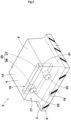
- FIG. 2 shows a partial perspective view of the tread portion 2 including the right-side shoulder circumferential groove 6 and one shoulder block 13 adjacent to the right-side shoulder circumferential groove 6 in FIG. 1 .
- the shoulder circumferential groove 6 as the circumferential groove 3 has a first groove wall 17 and a groove bottom 18.
- the first groove wall 17 defines a side wall surface of the shoulder block 13 of the land portion 4. That is, the first groove wall 17 is also a side wall surface on the shoulder circumferential groove 6 side of the shoulder block 13.
- the ground-contact surface 5 of the shoulder block 13 is connected to the first groove wall 17.
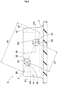
- FIG. 3 is a side view of FIG. 2 as viewed from the first groove wall 17 side.
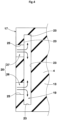
- FIG. 4 is a sectional view taken along a line IV-IV in FIG. 3 .
- arrows indicate one mode of flows of air.
- one longitudinal hole 19 and two or more lateral holes 20 connected to the longitudinal hole 19 are provided in the shoulder block 13.
- the two lateral holes 20 communicate with the one longitudinal hole 19.
- the longitudinal hole 19 has a longitudinal hole opening 21 having a closed contour on the ground-contact surface 5 of the shoulder block 13.
- the longitudinal hole opening 21 of the present embodiment is formed as an independent closed curve without communicating with any surrounding edges of the ground-contact surface 5 of the shoulder block 13.
- the longitudinal hole 19 is formed as a space extending inward in the tire radial direction from the longitudinal hole opening 21.
- the two or more lateral holes 20 each have a lateral hole opening 22 having a closed contour on the first groove wall 17.
- the lateral hole openings 22 of the present embodiment are formed as independent closed curves without communicating with each other.
- each lateral hole 20 is formed as a space extending in the tire axial direction from the lateral hole opening 22 and communicating with the longitudinal hole 19.
- Effects of the tire 1 configured as described above of the present embodiment are as follows. First, since the two or more lateral holes 20 extend in the tire axial direction from the lateral hole openings 22 and communicate with the longitudinal hole 19, a part of air flowing in the circumferential groove 3 (shoulder circumferential groove 6) enters the lateral holes 20 via the lateral hole openings 22 and flows into the longitudinal hole 19 during running with the tire. In addition, the air that has flowed into the longitudinal hole 19 exhibits pressure loss. Sound energy in the circumferential groove 3 is eliminated by this pressure loss, and thus air column resonance sound during running is reduced. The above effect can be obtained when the longitudinal hole 19 is not completely closed with the ground.
- the longitudinal hole 19 and the two or more lateral holes 20 respectively have the longitudinal hole opening 21 having a closed contour on the ground-contact surface 5 of the land portion 4 (shoulder block 13) and the lateral hole openings 22 each having a closed contour on the first groove wall 17. Furthermore, the two or more lateral holes 20 separately connect to the one longitudinal hole 19, whereby the respective lateral hole openings 22 can be formed small.
- the tire 1 of the present embodiment can improve noise performance while suppressing uneven wear of the land portion 4 (shoulder block 13).
- the shoulder block 13 as an object for describing the land portion 4
- the shoulder circumferential groove 6 as an object for describing the circumferential groove 3
- the present invention is not limited thereto.
- the crown block 15 instead of the shoulder block 13, may be the land portion 4 in which the longitudinal hole 19 and the lateral holes 20 are provided, or both the shoulder block 13 and the crown block 15 may be such land portions 4.
- the circumferential groove 3 at which the lateral holes 20 are provided may be the crown circumferential groove 7.
- the land portion 4 may be formed as a rib.
- the longitudinal hole opening 21 preferably has a longitudinally elongated shape having a width L 1 in the tire axial direction smaller than a length L2 in the tire circumferential direction.
- the longitudinal hole opening 21 preferably has a longitudinally elongated rectangular shape. Such a longitudinal hole opening 21 serves to suppress a decrease in stiffness and further improve uneven wear resistance, of the shoulder block 13 as the land portion 4.
- the width L1 in the tire axial direction of the longitudinal hole opening 21 is preferably set to be smaller than the groove width W of the circumferential groove 3. In a more preferable mode, the width L1 in the tire axial direction of the longitudinal hole opening 21 is, for example, set to be 1.5 to 2.5 mm. Such a longitudinal hole opening 21 serves to suppress a decrease in stiffness and further improve uneven wear resistance, of the shoulder block 13 as the land portion 4.
- FIG. 5 is a sectional view taken along a line V-V in FIG. 1 .
- the longitudinal hole 19 has a slit shape having a draft angle or the like but extending inward in the tire radial direction substantially in the contour of the longitudinal hole opening 21.
- Such a longitudinal hole shape serves to suppress a decrease in stiffness and further improve uneven wear resistance, of the shoulder block 13 as the land portion 4.
- a shape obtained by projecting the longitudinal hole 19 of the present embodiment on the first groove wall 17 in parallel to the tire axial direction is a rectangular shape 24 as indicated by broken lines.
- a shortest distance L3 in the tire axial direction between the first groove wall 17 and a groove wall 23 of the longitudinal hole 19 is preferably 10 to 30% of a width L4 in the tire axial direction of the shoulder block 13.
- the width L4 in the tire axial direction of the shoulder block 13 is a maximum width in the tire axial direction of the ground-contact surface 5 of the shoulder block 13 (land portion 4).
- the shortest distance L3 in the tire axial direction between the first groove wall 17 and the groove wall 23 of the longitudinal hole 19 is not less than 10% of the width L4 in the tire axial direction of the shoulder block 13, the thickness of rubber between the shoulder circumferential groove 6 and the shoulder block 13 is sufficiently ensured, and thus uneven wear of the shoulder block 13 can be suppressed.
- the shortest distance L3 in the tire axial direction between the first groove wall 17 and the groove wall 23 of the longitudinal hole 19 is not more than 30% of the width L4 in the tire axial direction of the shoulder block 13, no longitudinal hole 19 is disposed at the center, in which ground-contact pressure with respect to the ground-contact surface 5 becomes relatively high, of the shoulder block 13, and thus a decrease in steering stability can be suppressed.
- the lateral hole openings 22 are each formed in a circular shape, for example.
- the lateral holes 20 extend straight from the lateral hole openings 22 and communicate with the longitudinal hole 19.
- the lateral holes 20 of the present embodiment are each a cylindrical space.
- each lateral hole 20 is not limited to such a mode, and may be a rectangular parallelepiped or cubic space.
- the lateral holes 20 of the present embodiment include a first lateral hole 26, and a second lateral hole 27 provided inward of the first lateral hole 26 in the tire radial direction.
- the first lateral hole 26 may disappear. Even in such a case, a part of air flowing in the circumferential groove 3 can flow into the longitudinal hole 19 through the second lateral hole 27. Therefore, according to the present embodiment, the above-described effect can be maintained even if the tread portion 2 is worn.
- air can be discharged from different positions in the circumferential direction and the depth direction of the circumferential grooves 3, whereby air discharging performance is improved and noise due to air column resonance can be further suppressed.
- the volume of the first lateral hole 26 is preferably set to be equal to the volume of the second lateral hole 27.
- the amounts of air flowing into the longitudinal hole 19 through the lateral holes 20, respectively are less likely to be different from each other, and thus the air is likely to spread in the longitudinal hole 19 in a well-balanced manner. Therefore, pressure loss is effectively generated, and thus the sound energy in the circumferential groove 3 disappears and the effect of reducing air column resonance sound can also be increased.
- the total area of the lateral hole openings 22 of the two or more lateral holes 20 is preferably 20 to 60% of the area of the longitudinal hole opening 21 (shown in FIG. 2 ).
- the total area of the lateral hole openings 22 is not less than 20% of the area of the longitudinal hole opening 21, a sufficient amount of air is allowed to flow into the longitudinal hole 19 from the circumferential groove 3, and air column resonance sound can be more effectively reduced.
- stiffness of the land portion 4 is sufficiently ensured and uneven wear of the land portion 4 can be suppressed while maintaining pressure loss.
- a maximum diameter D1 of the lateral hole opening 22 of the first lateral hole 26 and a maximum diameter D2 of the lateral hole opening 22 of the second lateral hole 27 may be determined in consideration of pressure loss due to friction caused when air is passing through the lateral hole 20. As shown in FIG. 4 , air from the circumferential groove 3 also has pressure loss due to friction with an inner peripheral surface 25 of the lateral hole 20, when the air passes through each lateral hole 20. The maximum diameter D1 of the lateral hole opening 22 of the first lateral hole 26 and the maximum diameter D2 of the lateral hole opening 22 of the second lateral hole 27 influence generation of pressure loss due to this friction.
- each of the maximum diameter D 1 of the lateral hole opening 22 of the first lateral hole 26 and the maximum diameter D2 of the lateral hole opening 22 of the second lateral hole 27 is, for example, 2.0 to 6.0 mm.
- pressure loss due to friction with the inner peripheral surface 25 of the lateral hole 20 can be effectively utilized to further effectively reduce air column resonance sound.
- a separation distance L5 between the lateral hole openings 22 of the two or more lateral holes 20 is preferably 15 to 30% of a length L6 of a diagonal line 28 of the rectangular shape 24 obtained by projecting the longitudinal hole 19 on the first groove wall 17 in parallel to the tire axial direction.
- the separation distance L5 is defined as a distance between the centroids of the lateral hole openings 22 adjacent to each other.
- the maximum diameter D1 of the lateral hole opening 22 of the first lateral hole 26 and the maximum diameter D2 of the lateral hole opening 22 of the second lateral hole 27 can be set in the above magnitude range.
- a sufficient amount of air is allowed to flow into the longitudinal hole 19 from the circumferential groove 3, and air column resonance sound can be more effectively reduced.
- the two or more lateral holes 20 are preferably each disposed on the diagonal line 28 of the rectangular shape 24.
- the center of the first lateral hole 26 and the center of the second lateral hole 27 are disposed on the diagonal line 28.
- the present invention includes the following aspects.
- a tire including a tread portion, wherein
- the two or more lateral holes include a first lateral hole, and a second lateral hole provided inward of the first lateral hole in the tire radial direction.
- a shortest distance in the tire axial direction between the first groove wall and a groove wall of the longitudinal hole is 10 to 30% of a width in the tire axial direction of each of the blocks.
Landscapes
- Engineering & Computer Science (AREA)
- Mechanical Engineering (AREA)
- Tires In General (AREA)
Abstract
Description
- The present invention relates to a tire.
- A tread portion of a tire includes circumferential grooves extending in a tire circumferential direction for drainage. However, the circumferential grooves have been known to cause air column resonance during running on a dry road surface. To suppress the air column resonance, a pneumatic tire in which a resonator including an air chamber and a narrowed neck is provided in a tread portion thereof, is proposed (see
Japanese Patent No. 5013731 - In the case where the above-described resonator is provided in the tread portion, block stiffness or the like of the tread portion is decreased, and thus there is a problem that uneven wear such as heel-and-toe wear is likely to occur.
- The present invention has been made in view of the above-described problem, and a main object of the present invention is to provide a tire capable of improving noise performance while suppressing uneven wear.
- The present invention is directed to a tire including a tread portion, wherein the tread portion includes a circumferential groove extending in a tire circumferential direction and a land portion adjacent to the circumferential groove, the circumferential groove includes a first groove wall defining a side wall surface of the land portion, the land portion includes a ground-contact surface connected to the first groove wall, a longitudinal hole and two or more lateral holes are provided in the land portion, the longitudinal hole has a longitudinal hole opening having a closed contour on the ground-contact surface and extends inward in a tire radial direction from the longitudinal hole opening, and each of the two or more lateral holes has a lateral hole opening having a closed contour on a surface of the first groove wall and extends in a tire axial direction from the lateral hole opening so as to communicate with the longitudinal hole.
- As a result of adopting the above configuration, the tire according to the present invention can improve noise performance while suppressing uneven wear of the land portion.
-
-
FIG. 1 is a development view of a tread portion of a tire according to one embodiment of the present invention; -
FIG. 2 is a partial perspective view of the tread portion; -
FIG. 3 is a side view ofFIG. 2 as viewed from a first groove wall side; -
FIG. 4 is a sectional view taken along a line IV-IV inFIG. 3 ; and -
FIG. 5 is a sectional view taken along a line V-V inFIG. 1 . - One embodiment of the present invention will be described below with reference to the drawings.
-
FIG. 1 is a development of atread portion 2 of a tire 1 showing one embodiment of the present invention. The tire 1 of the present embodiment is a pneumatic tire, and is preferably a tire for a vehicle that is required to provide quietness, and particularly, a pneumatic tire for a passenger car. As shown inFIG. 1 , thetread portion 2 includes a pair of tread edges Te, Te, a plurality ofcircumferential grooves 3 extending in a tire circumferential direction between the pair of tread edges Te, Te, and landportions 4 demarcated by thecircumferential grooves 3. - The pair of tread edges Te, Te correspond to outermost edges in a tire axial direction of a ground-
contact surface 5 when 70% of a standardized load is applied to the tire 1 in a standardized state and thetread portion 2 is brought into contact with a plane at a camber angle of 0°. - In the case of a pneumatic tire for which various standards are defined, the "standardized state" is a state where the tire is fitted on a standardized rim and inflated to a standardized internal pressure and no load is applied to the tire. In the case of a non-pneumatic tire and a tire for which various standards are not defined, the standardized state represents a standard use state which corresponds to a purpose of use of the tire and in which no load is applied to the tire. In the present specification, unless otherwise specified, dimensions and the like of components of the tire are values measured in the standardized state.
- The "standardized rim" is a rim that is defined, in a standard system including a standard on which the tire is based, by the standard for each tire, and is, for example, the "standard rim" in the JATMA standard, the "Design Rim" in the TRA standard, or the "Measuring Rim" in the ETRTO standard.
- The "standardized internal pressure" is an air pressure that is defined, in a standard system including a standard on which the tire is based, by the standard for each tire, and is the "maximum air pressure" in the JATMA standard, the maximum value indicated in the table "TIRE LOAD LIMITS AT VARIOUS COLD INFLATION PRESSURES" in the TRA standard, or the "INFLATION PRESSURE" in the ETRTO standard.
- In the case of a pneumatic tire for which various standards are defined, the "standardized load" is a load that is defined, in a standard system including a standard on which the tire is based, by the standard for each tire, and is the "maximum load capacity" in the JATMA standard, the maximum value indicated in the table "TIRE LOAD LIMITS AT VARIOUS COLD INFLATION PRESSURES" in the TRA standard, or the "LOAD CAPACITY" in the ETRTO standard. In addition, in the case of a tire for which various standards are not defined, the "standardized load" refers to the maximum load applicable when the tire is used, according to the above-described standards.
- In the present embodiment, the
circumferential grooves 3 include a pair of shouldercircumferential grooves 6, and one or more crown circumferential grooves 7 disposed between the pair of shouldercircumferential grooves 6. A groove width W of eachcircumferential groove 3 is not particularly limited, but is, for example, not less than 3.0 mm and preferably not less than 4.0 mm, in order to ensure sufficient drainage performance and enhance resistance to hydroplaning. The groove width W is a groove width at the ground-contact surface 5 of thetread portion 2. In addition, a depth D (shown inFIG. 5 ) of thecircumferential groove 3 is also not particularly limited, but is, for example, not less than 5.0 mm and preferably not less than 6.0 mm. Thecircumferential groove 3 of the present embodiment linearly extends along the tire circumferential direction, but is not limited to such a mode. - In the present embodiment, the
land portions 4 include a pair ofshoulder land portions 8, and a pair ofcrown land portions 9 disposed between the pair ofshoulder land portions 8. Eachland portion 4 includes a plurality oflateral grooves 10 extending in the tire axial direction. Thus, theland portion 4 is formed as ablock array 12 in which a plurality ofblocks 11 are arranged in the tire circumferential direction. That is, eachshoulder land portion 8 and eachcrown land portion 9 of the present embodiment are respectively formed as ashoulder block array 14 in whichshoulder blocks 13 are arranged in the tire circumferential direction and acrown block array 16 in whichcrown blocks 15 are arranged in the tire circumferential direction. In another mode, theshoulder land portion 8 and/or thecrown land portion 9 may be formed as ribs (not shown) continuously extending in the tire circumferential direction. -
FIG. 2 shows a partial perspective view of thetread portion 2 including the right-side shouldercircumferential groove 6 and oneshoulder block 13 adjacent to the right-side shouldercircumferential groove 6 inFIG. 1 . As shown inFIG. 2 , in the present embodiment, the shouldercircumferential groove 6 as thecircumferential groove 3 has afirst groove wall 17 and agroove bottom 18. Thefirst groove wall 17 defines a side wall surface of theshoulder block 13 of theland portion 4. That is, thefirst groove wall 17 is also a side wall surface on the shouldercircumferential groove 6 side of theshoulder block 13. In addition, the ground-contact surface 5 of theshoulder block 13 is connected to thefirst groove wall 17. -
FIG. 3 is a side view ofFIG. 2 as viewed from thefirst groove wall 17 side.FIG. 4 is a sectional view taken along a line IV-IV inFIG. 3 . InFIG. 4 , arrows indicate one mode of flows of air. As shown inFIGS. 2 to 4 , onelongitudinal hole 19 and two or morelateral holes 20 connected to thelongitudinal hole 19 are provided in theshoulder block 13. In the present embodiment, the twolateral holes 20 communicate with the onelongitudinal hole 19. - The
longitudinal hole 19 has a longitudinal hole opening 21 having a closed contour on the ground-contact surface 5 of theshoulder block 13. The longitudinal hole opening 21 of the present embodiment is formed as an independent closed curve without communicating with any surrounding edges of the ground-contact surface 5 of theshoulder block 13. In addition, thelongitudinal hole 19 is formed as a space extending inward in the tire radial direction from the longitudinal hole opening 21. - The two or more
lateral holes 20 each have a lateral hole opening 22 having a closed contour on thefirst groove wall 17. Thelateral hole openings 22 of the present embodiment are formed as independent closed curves without communicating with each other. In addition, eachlateral hole 20 is formed as a space extending in the tire axial direction from the lateral hole opening 22 and communicating with thelongitudinal hole 19. - Effects of the tire 1 configured as described above of the present embodiment are as follows. First, since the two or more
lateral holes 20 extend in the tire axial direction from thelateral hole openings 22 and communicate with thelongitudinal hole 19, a part of air flowing in the circumferential groove 3 (shoulder circumferential groove 6) enters thelateral holes 20 via thelateral hole openings 22 and flows into thelongitudinal hole 19 during running with the tire. In addition, the air that has flowed into thelongitudinal hole 19 exhibits pressure loss. Sound energy in thecircumferential groove 3 is eliminated by this pressure loss, and thus air column resonance sound during running is reduced. The above effect can be obtained when thelongitudinal hole 19 is not completely closed with the ground. - In addition, in the tire 1 of the present embodiment, the
longitudinal hole 19 and the two or morelateral holes 20 respectively have the longitudinal hole opening 21 having a closed contour on the ground-contact surface 5 of the land portion 4 (shoulder block 13) and thelateral hole openings 22 each having a closed contour on thefirst groove wall 17. Furthermore, the two or morelateral holes 20 separately connect to the onelongitudinal hole 19, whereby the respectivelateral hole openings 22 can be formed small. With the above configuration, a decrease in stiffness of theland portion 4 in which thelongitudinal hole 19 and thelateral holes 20 are provided is suppressed, and thus uneven wear of theland portion 4 can be suppressed. - Therefore, the tire 1 of the present embodiment can improve noise performance while suppressing uneven wear of the land portion 4 (shoulder block 13). In the above embodiment, the
shoulder block 13 as an object for describing theland portion 4, and the shouldercircumferential groove 6 as an object for describing thecircumferential groove 3 are used. However, the present invention is not limited thereto. For example, instead of theshoulder block 13, thecrown block 15 may be theland portion 4 in which thelongitudinal hole 19 and the lateral holes 20 are provided, or both theshoulder block 13 and thecrown block 15 may besuch land portions 4. Similarly, thecircumferential groove 3 at which the lateral holes 20 are provided may be the crown circumferential groove 7. Furthermore, theland portion 4 may be formed as a rib. - Hereinafter, more preferable modes of the present invention will be described.
- As shown in
FIG. 1 , thelongitudinal hole opening 21 preferably has a longitudinally elongated shape having a width L 1 in the tire axial direction smaller than a length L2 in the tire circumferential direction. In particular, thelongitudinal hole opening 21 preferably has a longitudinally elongated rectangular shape. Such alongitudinal hole opening 21 serves to suppress a decrease in stiffness and further improve uneven wear resistance, of theshoulder block 13 as theland portion 4. - The width L1 in the tire axial direction of the
longitudinal hole opening 21 is preferably set to be smaller than the groove width W of thecircumferential groove 3. In a more preferable mode, the width L1 in the tire axial direction of thelongitudinal hole opening 21 is, for example, set to be 1.5 to 2.5 mm. Such alongitudinal hole opening 21 serves to suppress a decrease in stiffness and further improve uneven wear resistance, of theshoulder block 13 as theland portion 4. -
FIG. 5 is a sectional view taken along a line V-V inFIG. 1 . As shown inFIG. 2 andFIG. 5 , thelongitudinal hole 19 has a slit shape having a draft angle or the like but extending inward in the tire radial direction substantially in the contour of thelongitudinal hole opening 21. Such a longitudinal hole shape serves to suppress a decrease in stiffness and further improve uneven wear resistance, of theshoulder block 13 as theland portion 4. As shown inFIG. 3 , a shape obtained by projecting thelongitudinal hole 19 of the present embodiment on thefirst groove wall 17 in parallel to the tire axial direction is arectangular shape 24 as indicated by broken lines. - As shown in
FIG. 5 , a shortest distance L3 in the tire axial direction between thefirst groove wall 17 and agroove wall 23 of thelongitudinal hole 19 is preferably 10 to 30% of a width L4 in the tire axial direction of theshoulder block 13. In the present embodiment, the width L4 in the tire axial direction of theshoulder block 13 is a maximum width in the tire axial direction of the ground-contact surface 5 of the shoulder block 13 (land portion 4). When the shortest distance L3 in the tire axial direction between thefirst groove wall 17 and thegroove wall 23 of thelongitudinal hole 19 is not less than 10% of the width L4 in the tire axial direction of theshoulder block 13, the thickness of rubber between the shouldercircumferential groove 6 and theshoulder block 13 is sufficiently ensured, and thus uneven wear of theshoulder block 13 can be suppressed. Meanwhile, when the shortest distance L3 in the tire axial direction between thefirst groove wall 17 and thegroove wall 23 of thelongitudinal hole 19 is not more than 30% of the width L4 in the tire axial direction of theshoulder block 13, nolongitudinal hole 19 is disposed at the center, in which ground-contact pressure with respect to the ground-contact surface 5 becomes relatively high, of theshoulder block 13, and thus a decrease in steering stability can be suppressed. - As shown in
FIG. 2 andFIG. 3 , thelateral hole openings 22 are each formed in a circular shape, for example. In addition, the lateral holes 20 extend straight from thelateral hole openings 22 and communicate with thelongitudinal hole 19. Accordingly, the lateral holes 20 of the present embodiment are each a cylindrical space. However, eachlateral hole 20 is not limited to such a mode, and may be a rectangular parallelepiped or cubic space. - As shown in
FIG. 3 andFIG. 4 , the lateral holes 20 of the present embodiment include a firstlateral hole 26, and a secondlateral hole 27 provided inward of the firstlateral hole 26 in the tire radial direction. When thetread portion 2 is worn due to running with the tire 1, the firstlateral hole 26 may disappear. Even in such a case, a part of air flowing in thecircumferential groove 3 can flow into thelongitudinal hole 19 through the secondlateral hole 27. Therefore, according to the present embodiment, the above-described effect can be maintained even if thetread portion 2 is worn. In addition, air can be discharged from different positions in the circumferential direction and the depth direction of thecircumferential grooves 3, whereby air discharging performance is improved and noise due to air column resonance can be further suppressed. - The volume of the first
lateral hole 26 is preferably set to be equal to the volume of the secondlateral hole 27. In such a mode, the amounts of air flowing into thelongitudinal hole 19 through the lateral holes 20, respectively, are less likely to be different from each other, and thus the air is likely to spread in thelongitudinal hole 19 in a well-balanced manner. Therefore, pressure loss is effectively generated, and thus the sound energy in thecircumferential groove 3 disappears and the effect of reducing air column resonance sound can also be increased. - The total area of the
lateral hole openings 22 of the two or more lateral holes 20 (i.e., all the lateral holes 20 communicating with one longitudinal hole 19) is preferably 20 to 60% of the area of the longitudinal hole opening 21 (shown inFIG. 2 ). When the total area of thelateral hole openings 22 is not less than 20% of the area of thelongitudinal hole opening 21, a sufficient amount of air is allowed to flow into thelongitudinal hole 19 from thecircumferential groove 3, and air column resonance sound can be more effectively reduced. In addition, when the total area of thelateral hole opening 22 is not more than 60% of the area of thelongitudinal hole opening 21, stiffness of theland portion 4 is sufficiently ensured and uneven wear of theland portion 4 can be suppressed while maintaining pressure loss. - A maximum diameter D1 of the lateral hole opening 22 of the first
lateral hole 26 and a maximum diameter D2 of the lateral hole opening 22 of the secondlateral hole 27 may be determined in consideration of pressure loss due to friction caused when air is passing through thelateral hole 20. As shown inFIG. 4 , air from thecircumferential groove 3 also has pressure loss due to friction with an innerperipheral surface 25 of thelateral hole 20, when the air passes through eachlateral hole 20. The maximum diameter D1 of the lateral hole opening 22 of the firstlateral hole 26 and the maximum diameter D2 of the lateral hole opening 22 of the secondlateral hole 27 influence generation of pressure loss due to this friction. From this viewpoint, each of the maximum diameter D 1 of the lateral hole opening 22 of the firstlateral hole 26 and the maximum diameter D2 of the lateral hole opening 22 of the secondlateral hole 27 is, for example, 2.0 to 6.0 mm. Thus, pressure loss due to friction with the innerperipheral surface 25 of thelateral hole 20 can be effectively utilized to further effectively reduce air column resonance sound. - As shown in
FIG. 3 andFIG. 4 , a separation distance L5 between thelateral hole openings 22 of the two or morelateral holes 20 is preferably 15 to 30% of a length L6 of adiagonal line 28 of therectangular shape 24 obtained by projecting thelongitudinal hole 19 on thefirst groove wall 17 in parallel to the tire axial direction. The separation distance L5 is defined as a distance between the centroids of thelateral hole openings 22 adjacent to each other. When the separation distance L5 is not less than 15% of the length L6, air flowing into thelongitudinal hole 19 from one of the two or morelateral holes 20 and air flowing into thelongitudinal hole 19 from the other of the two or morelateral holes 20 are less likely to interfere with each other, and pressure loss is effectively generated. Meanwhile, when the separation distance L5 is not more than 30% of the length L6, the maximum diameter D1 of the lateral hole opening 22 of the firstlateral hole 26 and the maximum diameter D2 of the lateral hole opening 22 of the secondlateral hole 27 can be set in the above magnitude range. Thus, a sufficient amount of air is allowed to flow into thelongitudinal hole 19 from thecircumferential groove 3, and air column resonance sound can be more effectively reduced. - From the viewpoint of setting the separation distance L5 between the
lateral hole openings 22 of the two or morelateral holes 20 to be longer as described above, the two or morelateral holes 20 are preferably each disposed on thediagonal line 28 of therectangular shape 24. In a more preferable example, the center of the firstlateral hole 26 and the center of the secondlateral hole 27 are disposed on thediagonal line 28. Thus, air flowing into thelongitudinal hole 19 through the twolateral holes 20 is likely to spread in thelongitudinal hole 19 in a well-balanced manner. Therefore, pressure loss is increased, sound energy disappears in thecircumferential groove 3, and thus the effect of reducing air column resonance sound is increased. - Although one embodiment of the present invention has been described in detail above, the present invention is not limited to the above specific embodiment, and various modifications can be made to implement the present invention.
- The present invention includes the following aspects.
- A tire including a tread portion, wherein
- the tread portion includes a circumferential groove extending in a tire circumferential direction and a land portion adjacent to the circumferential groove,
- the circumferential groove includes a first groove wall defining a side wall surface of the land portion,
- the land portion includes a ground-contact surface connected to the first groove wall,
- a longitudinal hole and two or more lateral holes are provided in the land portion,
- the longitudinal hole has a longitudinal hole opening having a closed contour on the ground-contact surface and extends inward in a tire radial direction from the longitudinal hole opening, and
- each of the two or more lateral holes has a lateral hole opening having a closed contour on a surface of the first groove wall and extends in a tire axial direction from the lateral hole opening so as to communicate with the longitudinal hole.
- The tire according to Present Invention 1, wherein a total area of the lateral hole openings of the two or more lateral holes is 20 to 60% of an area of the longitudinal hole opening.
- The tire according to
Present Invention 1 or 2, wherein a maximum diameter of each lateral hole opening is 2.0 to 6.0 mm. - The tire according to any one of Present Inventions 1 to 3, wherein
- a shape obtained by projecting the longitudinal hole on the first groove wall is a rectangular shape, and
- a separation distance between the lateral hole openings of the two or more lateral holes is 15 to 30% of a length of a diagonal line of the rectangular shape.
- The tire according to any one of Present Inventions 1 to 4, wherein the two or more lateral holes are each disposed on the diagonal line of the rectangular shape.
- The tire according to any one of Present Inventions 1 to 5, wherein the two or more lateral holes include a first lateral hole, and a second lateral hole provided inward of the first lateral hole in the tire radial direction.
- The tire according to any one of Present Inventions 1 to 6, wherein the land portion includes a block demarcated by lateral grooves extending in the tire axial direction.
- The tire according to Present Invention 7, wherein a shortest distance in the tire axial direction between the first groove wall and a groove wall of the longitudinal hole is 10 to 30% of a width in the tire axial direction of each of the blocks.
Claims (8)
- A tire (1) comprising a tread portion (2), whereinthe tread portion (2) includes a circumferential groove (3) extending in a tire circumferential direction and a land portion (4) adjacent to the circumferential groove (3),the circumferential groove (3) includes a first groove wall (17) defining a side wall surface of the land portion (4),the land portion (4) includes a ground-contact surface (5) connected to the first groove wall (17),a longitudinal hole (19) and two or more lateral holes (20) are provided in the land portion (4),the longitudinal hole (19) has a longitudinal hole opening (21) having a closed contour on the ground-contact surface (5) and extends inward in a tire radial direction from the longitudinal hole opening (21), andeach of the two or more lateral holes (20) has a lateral hole opening (22) having a closed contour on a surface of the first groove wall (17) and extends in a tire axial direction from the lateral hole opening (22) so as to communicate with the longitudinal hole (19).
- The tire (1) according to claim 1, wherein a total area of the lateral hole openings (22) of the two or more lateral holes (20) is 20 to 60% of an area of the longitudinal hole opening (21).
- The tire (1) according to claim 1 or 2, wherein a maximum diameter (D1, D2) of each lateral hole opening (22) is 2.0 to 6.0 mm.
- The tire (1) according to any one of claims 1 to 3, whereina shape obtained by projecting the longitudinal hole (19) on the first groove wall (17) is a rectangular shape, anda separation distance (L5) between the lateral hole openings (22) of the two or more lateral holes (20) is 15 to 30% of a length (L6) of a diagonal line (28) of the rectangular shape.
- The tire (1) according to claim 4, wherein the two or more lateral holes (20) are each disposed on the diagonal line (28) of the rectangular shape.
- The tire (1) according to any one of claims 1 to 5, wherein the two or more lateral holes (20) include a first lateral hole (26), and a second lateral hole (27) provided inward of the first lateral hole (26) in the tire radial direction.
- The tire (1) according to any one of claims 1 to 6, wherein the land portion (4) includes a block (11) demarcated by lateral grooves (10) extending in the tire axial direction.
- The tire (1) according to claim 7, wherein a shortest distance (L3) in the tire axial direction between the first groove wall (17) and a groove wall (23) of the longitudinal hole (19) is 10 to 30% of a width (L4) in the tire axial direction of each of the blocks (11).
Applications Claiming Priority (1)
| Application Number | Priority Date | Filing Date | Title |
|---|---|---|---|
| JP2023065852A JP2024151984A (en) | 2023-04-13 | 2023-04-13 | tire |
Publications (2)
| Publication Number | Publication Date |
|---|---|
| EP4446130A1 true EP4446130A1 (en) | 2024-10-16 |
| EP4446130B1 EP4446130B1 (en) | 2026-01-14 |
Family
ID=90717494
Family Applications (1)
| Application Number | Title | Priority Date | Filing Date |
|---|---|---|---|
| EP24168268.1A Active EP4446130B1 (en) | 2023-04-13 | 2024-04-03 | Tire |
Country Status (2)
| Country | Link |
|---|---|
| EP (1) | EP4446130B1 (en) |
| JP (1) | JP2024151984A (en) |
Citations (5)
| Publication number | Priority date | Publication date | Assignee | Title |
|---|---|---|---|---|
| JPH0776203A (en) * | 1993-06-17 | 1995-03-20 | Sumitomo Rubber Ind Ltd | Pneumatic tire |
| US20080092999A1 (en) * | 2006-10-23 | 2008-04-24 | Toyo Tire & Rubber Co., Ltd. | Pneumatic tire |
| EP2011671A1 (en) * | 2006-03-31 | 2009-01-07 | Bridgestone Corporation | Pneumatic tire |
| JP5013731B2 (en) | 2006-03-31 | 2012-08-29 | 株式会社ブリヂストン | Pneumatic tire |
| US20210070107A1 (en) * | 2019-09-10 | 2021-03-11 | Toyo Tire Corporation | Pneumatic tire |
-
2023
- 2023-04-13 JP JP2023065852A patent/JP2024151984A/en active Pending
-
2024
- 2024-04-03 EP EP24168268.1A patent/EP4446130B1/en active Active
Patent Citations (5)
| Publication number | Priority date | Publication date | Assignee | Title |
|---|---|---|---|---|
| JPH0776203A (en) * | 1993-06-17 | 1995-03-20 | Sumitomo Rubber Ind Ltd | Pneumatic tire |
| EP2011671A1 (en) * | 2006-03-31 | 2009-01-07 | Bridgestone Corporation | Pneumatic tire |
| JP5013731B2 (en) | 2006-03-31 | 2012-08-29 | 株式会社ブリヂストン | Pneumatic tire |
| US20080092999A1 (en) * | 2006-10-23 | 2008-04-24 | Toyo Tire & Rubber Co., Ltd. | Pneumatic tire |
| US20210070107A1 (en) * | 2019-09-10 | 2021-03-11 | Toyo Tire Corporation | Pneumatic tire |
Also Published As
| Publication number | Publication date |
|---|---|
| EP4446130B1 (en) | 2026-01-14 |
| JP2024151984A (en) | 2024-10-25 |
Similar Documents
| Publication | Publication Date | Title |
|---|---|---|
| US11427033B2 (en) | Tire | |
| US9302552B2 (en) | Pneumatic tire | |
| US10343462B2 (en) | Pneumatic tire | |
| US9174492B2 (en) | Pneumatic tire | |
| US8640750B2 (en) | Pneumatic tire with tread having shoulder blocks and crown blocks | |
| US7178570B2 (en) | Pneumatic tire including main and auxiliary oblique grooves in axially inner region of tread | |
| US9783005B2 (en) | Pneumatic tire | |
| US9085201B2 (en) | Pneumatic tire | |
| US10471776B2 (en) | Pneumatic tire | |
| US10800212B2 (en) | Pneumatic tire | |
| US9150056B2 (en) | Pneumatic tire | |
| US8267133B2 (en) | Pneumatic tire | |
| US8225833B2 (en) | Pneumatic tire | |
| US20110024012A1 (en) | Pneumatic tire | |
| US20140305559A1 (en) | Pneumatic tire | |
| JP4107393B1 (en) | Pneumatic tire | |
| US10766311B2 (en) | Pneumatic tire | |
| CN105307873B (en) | Pneumatic tire | |
| US10723178B2 (en) | Tire | |
| KR20180025808A (en) | Pneumatic tire | |
| US11654721B2 (en) | Tire | |
| US20190084352A1 (en) | Tire | |
| EP4446130B1 (en) | Tire | |
| US20240343069A1 (en) | Tire | |
| US11505006B2 (en) | Tyre |
Legal Events
| Date | Code | Title | Description |
|---|---|---|---|
| PUAI | Public reference made under article 153(3) epc to a published international application that has entered the european phase |
Free format text: ORIGINAL CODE: 0009012 |
|
| STAA | Information on the status of an ep patent application or granted ep patent |
Free format text: STATUS: THE APPLICATION HAS BEEN PUBLISHED |
|
| AK | Designated contracting states |
Kind code of ref document: A1 Designated state(s): AL AT BE BG CH CY CZ DE DK EE ES FI FR GB GR HR HU IE IS IT LI LT LU LV MC ME MK MT NL NO PL PT RO RS SE SI SK SM TR |
|
| STAA | Information on the status of an ep patent application or granted ep patent |
Free format text: STATUS: REQUEST FOR EXAMINATION WAS MADE |
|
| 17P | Request for examination filed |
Effective date: 20250314 |
|
| P01 | Opt-out of the competence of the unified patent court (upc) registered |
Free format text: CASE NUMBER: APP_12424/2025 Effective date: 20250313 |
|
| GRAP | Despatch of communication of intention to grant a patent |
Free format text: ORIGINAL CODE: EPIDOSNIGR1 |
|
| STAA | Information on the status of an ep patent application or granted ep patent |
Free format text: STATUS: GRANT OF PATENT IS INTENDED |
|
| GRAS | Grant fee paid |
Free format text: ORIGINAL CODE: EPIDOSNIGR3 |
|
| GRAA | (expected) grant |
Free format text: ORIGINAL CODE: 0009210 |
|
| STAA | Information on the status of an ep patent application or granted ep patent |
Free format text: STATUS: THE PATENT HAS BEEN GRANTED |
|
| INTG | Intention to grant announced |
Effective date: 20251112 |
|
| AK | Designated contracting states |
Kind code of ref document: B1 Designated state(s): AL AT BE BG CH CY CZ DE DK EE ES FI FR GB GR HR HU IE IS IT LI LT LU LV MC ME MK MT NL NO PL PT RO RS SE SI SK SM TR |
|
| REG | Reference to a national code |
Ref country code: CH Ref legal event code: F10 Free format text: ST27 STATUS EVENT CODE: U-0-0-F10-F00 (AS PROVIDED BY THE NATIONAL OFFICE) Effective date: 20260114 Ref country code: GB Ref legal event code: FG4D |
|
| REG | Reference to a national code |
Ref country code: DE Ref legal event code: R096 Ref document number: 602024002005 Country of ref document: DE |
|
| REG | Reference to a national code |
Ref country code: IE Ref legal event code: FG4D |
|
| PGFP | Annual fee paid to national office [announced via postgrant information from national office to epo] |
Ref country code: FR Payment date: 20260309 Year of fee payment: 3 |