EP4446128A1 - Tire - Google Patents
Tire Download PDFInfo
- Publication number
- EP4446128A1 EP4446128A1 EP22903754.4A EP22903754A EP4446128A1 EP 4446128 A1 EP4446128 A1 EP 4446128A1 EP 22903754 A EP22903754 A EP 22903754A EP 4446128 A1 EP4446128 A1 EP 4446128A1
- Authority
- EP
- European Patent Office
- Prior art keywords
- tire
- rubber
- communication device
- thermal
- carcass
- Prior art date
- Legal status (The legal status is an assumption and is not a legal conclusion. Google has not performed a legal analysis and makes no representation as to the accuracy of the status listed.)
- Granted
Links
Images


Classifications
-
- B—PERFORMING OPERATIONS; TRANSPORTING
- B60—VEHICLES IN GENERAL
- B60C—VEHICLE TYRES; TYRE INFLATION; TYRE CHANGING; CONNECTING VALVES TO INFLATABLE ELASTIC BODIES IN GENERAL; DEVICES OR ARRANGEMENTS RELATED TO TYRES
- B60C19/00—Tyre parts or constructions not otherwise provided for
-
- B—PERFORMING OPERATIONS; TRANSPORTING
- B60—VEHICLES IN GENERAL
- B60C—VEHICLE TYRES; TYRE INFLATION; TYRE CHANGING; CONNECTING VALVES TO INFLATABLE ELASTIC BODIES IN GENERAL; DEVICES OR ARRANGEMENTS RELATED TO TYRES
- B60C13/00—Tyre sidewalls; Protecting, decorating, marking, or the like, thereof
- B60C13/003—Tyre sidewalls; Protecting, decorating, marking, or the like, thereof characterised by sidewall curvature
-
- B—PERFORMING OPERATIONS; TRANSPORTING
- B60—VEHICLES IN GENERAL
- B60C—VEHICLE TYRES; TYRE INFLATION; TYRE CHANGING; CONNECTING VALVES TO INFLATABLE ELASTIC BODIES IN GENERAL; DEVICES OR ARRANGEMENTS RELATED TO TYRES
- B60C17/00—Tyres characterised by means enabling restricted operation in damaged or deflated condition; Accessories therefor
- B60C17/0009—Tyres characterised by means enabling restricted operation in damaged or deflated condition; Accessories therefor comprising sidewall rubber inserts, e.g. crescent shaped inserts
-
- B—PERFORMING OPERATIONS; TRANSPORTING
- B60—VEHICLES IN GENERAL
- B60C—VEHICLE TYRES; TYRE INFLATION; TYRE CHANGING; CONNECTING VALVES TO INFLATABLE ELASTIC BODIES IN GENERAL; DEVICES OR ARRANGEMENTS RELATED TO TYRES
- B60C1/00—Tyres characterised by the chemical composition or the physical arrangement or mixture of the composition
- B60C1/0025—Compositions of the sidewalls
-
- B—PERFORMING OPERATIONS; TRANSPORTING
- B60—VEHICLES IN GENERAL
- B60C—VEHICLE TYRES; TYRE INFLATION; TYRE CHANGING; CONNECTING VALVES TO INFLATABLE ELASTIC BODIES IN GENERAL; DEVICES OR ARRANGEMENTS RELATED TO TYRES
- B60C13/00—Tyre sidewalls; Protecting, decorating, marking, or the like, thereof
-
- B—PERFORMING OPERATIONS; TRANSPORTING
- B60—VEHICLES IN GENERAL
- B60C—VEHICLE TYRES; TYRE INFLATION; TYRE CHANGING; CONNECTING VALVES TO INFLATABLE ELASTIC BODIES IN GENERAL; DEVICES OR ARRANGEMENTS RELATED TO TYRES
- B60C9/00—Reinforcements or ply arrangement of pneumatic tyres
- B60C9/02—Carcasses
- B60C2009/0269—Physical properties or dimensions of the carcass coating rubber
-
- B—PERFORMING OPERATIONS; TRANSPORTING
- B60—VEHICLES IN GENERAL
- B60C—VEHICLE TYRES; TYRE INFLATION; TYRE CHANGING; CONNECTING VALVES TO INFLATABLE ELASTIC BODIES IN GENERAL; DEVICES OR ARRANGEMENTS RELATED TO TYRES
- B60C9/00—Reinforcements or ply arrangement of pneumatic tyres
- B60C9/02—Carcasses
- B60C9/0238—Carcasses characterised by special physical properties of the carcass ply
Definitions
- This disclosure relates to a tire.
- Our tire is a tire, including
- Our tire can be suitable for use in any type of pneumatic tire, particularly a passenger vehicle pneumatic tire.
- the tire width direction is represented by a reference sign "WD”
- the tire radial direction is represented by a reference sign “RD”
- the tire circumferential direction is represented by a reference sign "CD”.
- the side near the tire inner cavity is referred to as “tire inner side” and the side far from the tire inner cavity from is referred to as “tire outer side”.
- Figs. 1 illustrates a tire 1 according to one of the disclosed embodiments.
- Fig. 1 is a cross-sectional view in a tire width direction illustrating a portion of a tire according to one of the disclosed embodiments (specifically, a portion of the tire on one side in relation to the tire equatorial plane CL).
- the tire 1 according to the embodiment in Fig. 1 is a passenger vehicle pneumatic tire.
- the tire 1 according to any one of the disclosed embodiments can be any type of a tire.
- the tire 1 includes a tire body 1M and a communication device 10.
- the tire body 1M corresponds to a portion of the tire 1 excluding the communication device 10.
- the positional relationship, dimensions, and the like of the components shall be determined under reference conditions where the tire 1 is installed on an applicable rim, set at a prescribed internal pressure, and unloaded.
- the width, in a tire width direction, of a contact patch that is contact with a road surface under conditions where the tire 1 is installed in an applicable rim, set at a prescribed internal pressure, and subjected to maximum load is referred to as the ground contact width of a tire, and an end of the contact patch in the tire width direction is referred to as ground contact end.
- the term "applicable rim” refers to a standard rim (Measuring Rim in STANDARDS MANUAL of ETRTO and Design Rim in YEAR BOOK of TRA) having an applicable size that is specified or will be specified in an industrial standard effective in the region where pneumatic tires are produced and used, such as JATMA YEAR BOOK of JATMA (the Japan Automobile Tyre Manufacturers Association) in Japan, STANDARDS MANUAL of ETRTO (The European Tyre and Rim Technical Organisation) in Europe, and YEAR BOOK of TRA (The Tire and Rim Association, Inc.) in the United States.
- JATMA YEAR BOOK of JATMA the Japan Automobile Tyre Manufacturers Association
- STANDARDS MANUAL of ETRTO The European Tyre and Rim Technical Organisation
- TRA The Tire and Rim Association, Inc.
- the term “applicable rim” refers to a rim having a width corresponding to the bead width of a pneumatic tire.
- the “applicable rim” includes sizes that will be specified in the above-described industrial standards, in addition to currently specified sizes. Examples of “size that will be specified” can include a size specified as "FUTURE DEVELOPMENTS" in ETRTO 2013 version.
- the term “prescribed internal pressure” refers to an air pressure corresponding to the maximum load capacity of one wheel having an applicable size and ply rating that is specified or will be specified in an industrial standard such as the above-described JATMA YEAR BOOK (maximum air pressure).
- the term “prescribed internal pressure” refers to an air pressure corresponding to the maximum load capacity defined for each vehicle in which the tire is installed (maximum air pressure).
- maximum load refers to a load corresponding to the maximum load capacity of a tire having an applicable size defined in the above-described industrial standard, or with regard to sizes not specified in the above-described industrial standards, refers to a load corresponding to the maximum load capacity specified for each vehicle in which a tire is installed.
- the tire body 1M includes the tread portion 1a, a pair of sidewall portions 1b extending from both ends of the tread portion 1a in the tire width direction toward the tire radially inner side, and a pair of bead portions 1c provided at an end, on the tire radially inner side, of each of the sidewall portions 1b.
- the tread portion 1a is a tire widthwise portion, of the tire body 1M, between a pair of ground contact ends.
- the tread portion 1a is a tire widthwise portion, of the tire body 1M, between a pair of ground contact ends.
- the bead portion 1c is configured to be in contact with a rim on the tire radially inner side and the tire widthwise outer side when the tire 1 is installed on the rim.
- the tire body 1M includes a pair of tire side portions 1d extending from both ends of the tread portion 1a in the tire width direction toward the tire radially inner side.
- the tire side portion 1d consists of a sidewall portion 1b and a bead portion 1c.
- the tire body 1M includes a pair of bead cores 4a, a pair of bead fillers 4b, a carcass 5, a belt 6, a tread rubber 7, a side rubber 8, an inner liner 9, and a pair of side reinforcing rubbers 2.
- the bead cores 4a are embedded in the respective bead portions 1c.
- the bead core 4a includes a plurality of bead wire coated with a rubber.
- the bead wire is preferably made of metal (for example, steel).
- the bead wire can consist of, for example, monofilaments or twisted wires.
- the bead wire may be made of organic fibers or carbon fibers.
- the bead fillers 4b is positioned on the tire radially outer side relative to the respective bead cores 4a.
- the bead filler 4b extends, in a tapered manner, toward the tire radially outer side.
- the bead filler 4b is made of rubber, for example.
- the carcass 5 ranges between a pair of bead cores 4a and extends to have a toroidal shape.
- the carcass 5 is constituted by one or more (in the embodiment in Fig. 1 , two) carcass plies 5a.
- Each of the carcass plies 5a includes one or more carcass cords 5c, and a coating rubber 5r coating a carcass cord 5c ( Fig. 1 ).
- the carcass cord 5c can be formed by monofilaments or twisted wires.
- the carcass cord 5c is preferably made of organic fibers such as polyester, nylon, rayon, and aramid.
- the carcass ply 5a includes a ply main body 5M between a pair of bead cores 4a.
- the carcass ply 5a can further include ply turn-up portions 5T that extend from both ends of the ply main body 5M and are turned up around the bead cores 4a from the tire widthwise inner side toward the tire widthwise outer side.
- the carcass ply 5a may not include a ply turn-up portion 5 T.
- the ply main body 5M is positioned on the tire widthwise inner side relative to the bead filler 4b and the bead core 4a.
- the ply turn-up portion 5T is positioned on the tire widthwise outer side relative to the bead filler 4b and the bead core 4a.
- the carcass 5 is preferably of radial structure and may be of bias structure.
- the belt 6 is disposed on the tire radially outer side in relation to the crown portion of the carcass 5.
- the belt 6 includes one or more belt layers 6a.
- Each of the belt layers 6a includes one or more belt cords and a coating rubber coating the belt cord.
- the belt cord can be formed of monofilaments or twisted wires.
- the belt cord can be made of metal (for example, steel) and can also be made of organic fibers such as polyester, nylon, rayon, and aramid.
- the tread rubber 7 is positioned on the tire radially outer side of the belt 6.
- the tread rubber 7 constitutes a tread surface, which is a surface on the tire radially outer side of the tread portion 1a.
- a tread pattern is formed on the tread surface.
- the side rubber 8 is positioned on the sidewall portion 1b.
- the side rubber 8 constitutes an outer surface, on the tire widthwise outer side, of the sidewall portion 1b.
- the side rubber 8 is positioned on the tire widthwise outer side relative to the carcass 5.
- the side rubber 8 is positioned on the tire widthwise outer side relative to the bead filler 4b.
- the side rubber 8 is formed to be integrated with the tread rubber 7.
- the inner liner 9 is disposed on the tire inner side of the carcass, and can be laminated, for example, on the tire inner side of the carcass 5.
- the inner liner 9 is made of a butyl-based rubber having low air permeability, for example.
- examples of the butyl-based rubbers include butyl rubbers and halogenated butyl rubbers, which are derivatives of butyl rubbers.
- the inner liner 9 is not limited to a butyl-based rubber and may be made of other rubber compositions, resins, or elastomers.
- a side reinforcing rubber 2 is disposed in the sidewall portion 1b.
- the side reinforcing rubbers 2 are embedded in the respective sidewall portions 1b.
- Each of the side reinforcing rubbers 2 is disposed on the tire widthwise inner side of the carcass 5.
- Each of the side reinforcing rubbers 2 is disposed on the tire widthwise outer side of the inner liner 9.
- the side reinforcing rubber 2 has a crescent-shaped cross section, and in a cross-section in the tire width direction, the thickness of the crescent-shaped cross section gradually decrease toward each of the inner side and the outer side in the tire radial direction, and in addition, the crescent-shaped cross section is curved in a convex manner toward the tire widthwise outer side. In this way, the tire 1 is configured as a run flat tire.
- the side reinforcing rubber 2 is configured to reinforce the tire side portion 1d, and under conditions where the internal pressure of the tire 1 is low due to puncture and the like, contributes to supporting of vehicle body weight and suppress vertical deflection of the tire 1, and as a result, allows for running over a certain distance.
- the communication device 10 will be described below.
- the communication device 10 can be of any configuration as long as the configuration enables wireless communication between the communication device 10 and a predetermined external device (for example, a reader or reader/writer) located at the exterior of the tire 1, and thus, there is no particular limitation on the configuration of the communication device 10.
- a predetermined external device for example, a reader or reader/writer
- the communication device 10 preferably includes a RF tag.
- the RF tag is also referred to as "RFID tag”.
- the RF tag is preferably of passive type but can also be of active type.
- the communication device 10 can include an accelerometer detecting the acceleration of the tire 1, and an internal pressure sensor detecting the internal pressure of the tire 1, and the like, instead of or in addition to the RF tag.
- Figs. 2 and 3 illustrates an example of the communication device 10.
- the communication device 10 includes a RF tag.
- the communication device 10 includes a RF tag 10e and a coating portion 10f.
- the RF tag 10e includes an IC chip 10c and an antenna portion 10b.
- the RF tag 10e is of passive type.
- the IC chip 10c operates, for example, by an induced electromotive force generated by a radio wave received by the antenna portion 10b.
- the IC chip 10c includes a controller and a memory unit, for example.
- the memory unit can store any information.
- the memory unit can store identification information of the tire 1.
- the identification information of the tire 1 is, for example, identification information that is unique to the tire 1 and can identify each tire from the tires, such as the manufacturer of the tire 1, the manufacturing plant of the tire 1, and the date of manufacture of the tire 1.
- the memory unit can store tire historical information such as the running distance of a tire, the number of sudden braking, the number of sudden starting, and the number of sudden cornering situation.
- a sensor detecting, for example, a tire internal temperature, a tire internal pressure, a tire acceleration is provided in a tire inner cavity and the memory unit stores information detected by the sensors.
- the RF tag 10e can wirelessly communicate with the sensor via the antenna portion 10b to obtain the information detected by the sensor.
- the controller is configured to enables reading of information from the memory unit.
- the antenna portion 10b includes a pair of antennas 10b1, 10b2.
- the pair of antenna 10b1, 10b2 are connected to opposite ends of the IC chip 10c, respectively.
- the antenna portion 10b is configured to allow for transmitting information to and receiving information from the above-described predetermined external device located at the exterior of the tire 1.
- each of the antennas 10b 1, 10b2 extends in a straight line, but each of the antennas 10b1, 10b2 may extend to have any shape such as waved shape.
- the entirety of the RF tag 10e is covered with the coating portion 10f.
- the coating portion 10f is formed of a rubber or a resin, for example.
- a coating portion 10f includes a pair of sheet-shaped coating members 10f1, 10f2.
- the pair of coating members 10f1, 10f2 are stacked to sandwich the RF tag 10e between the pair of coating members 10f1, 10f2.
- the pair of coating members 10f1, 10f2 are preferably fixed to each other, for example, by adhesion.
- the coating portion 10f may be constituted by one member.
- the coating portion 10f has a quadrilateral shape in a planar view.
- the coating portion 10f can have any shape in a planar view.
- the communication device 10 may not include the coating portion 10f, that is, can be constituted solely by the RF tag 10e.
- the communication device 10 configured as described above can receive information transmitted on a radio wave or a magnetic field from the above-described predetermined external device. Rectification (in the case of radio wave) or resonance (in the case of a magnetic field) generates power in the antenna portion 10b of the communication device 10, and the memory unit and the controller of the IC chip 10c perform a predetermined operation. For example, the controller reads information in the memory unit and returns (transmits) the information on a radio wave or a magnetic field from the antenna portion 10b to the above-described predetermined external device.
- the above-described predetermined external device receives the radio waves or the magnetic fields from the communication device 10. The above-described predetermined external device can retrieve the received information to obtain the information stored in the memory unit of the IC chip 10c in the communication device 10.
- the communication device 10 can have any configuration other than the configuration illustrated in this example.
- the communication device 10 can be provided with a longitudinal direction LD, a short-side direction SD, and a thickness direction TD.
- the longitudinal direction LD, the short-side direction SD, and the thickness direction TD are perpendicular to one another.
- the longitudinal direction LD of the communication device 10 is parallel to the extending direction of the antenna portion 10b.
- the extending direction of the antenna portion 10b refers to the extending direction of the amplitude centerline of each of the antennas 10b 1, 10b2.
- the thickness direction TD of the communication device 10 refers to the thickness direction of the coating portion 10f, and when the communication device 10 does not include the coating portion 10f, refers to the thickness direction of the IC chip 10c.
- the length of the RF tag 10e in the longitudinal direction LD is preferably 20 mm or more or 50 mm or more, for example.
- the length of the RF tag 10e in the longitudinal direction LD is preferably 100 mm or less or 70 mm or less, for example.
- the length of the RF tag 10e in the short-side direction SD is preferably 10 mm or less or 8 mm or less, for example.
- the length of the RF tag 10e in the thickness direction TD is preferably 5 mm or less or 2 mm or less, for example.
- the length of the communication device 10 in the longitudinal direction LD is preferably 30 mm or more or 60 mm or more, for example.
- the length of the RF tag 10e in the longitudinal direction LD is preferably 110 mm or less or 80 mm or less, for example.
- the length of the communication device 10 in the short-side direction SD is preferably 20 mm or less or 15 mm or less, for example.
- the length of the communication device 10 in the thickness direction TD is preferably 6 mm or less or 3 mm or less, for example.
- each of the coating members 10f1, 10f2 of the coating portion 10f is preferably 0.5 mm or more, for example.
- the thickness of each of the coating members 10f1, 10f2 of the coating portion 10f is preferably 1 mm or less, for example.
- the communication device 10 is embedded in the tire body 1M.
- the communication device 10 can be disposed at any position in the tire body 1M.
- the raw tire constituting the tire body 1M and the communication device 10 are accommodated in a mold for forming a tire and subjected to vulcanization molding.
- the communication device 10 can be attached on an outer surface or inner surface of the tire body 1M, instead of being embedded in the tire body 1M.
- the tire 1 (specifically, the tire body 1M) includes one or more low-thermal-conductivity members 3 having a lower thermal conductivity than that of the side reinforcing rubber 2.
- the one or more low-thermal-conductivity members 3 are positioned between the side reinforcing rubber 2 and the communication device 10.
- the carcass cords 5c (cords) of the carcass 5 constitute the respective low-thermal-conductivity members 3.
- each of the low-thermal-conductivity members 3 is constituted by the carcass cord 5c (cord) of the carcass 5.
- the carcass cord 5c may be made of organic fibers such as polyester, nylon, rayon, and aramid.
- the "thermal conductivity" of the low-thermal-conductivity member 3 shall be measured in accordance with JIS R 1611:2010.
- the low-thermal-conductivity member 3 is constituted by a member other than the cord (such as a rubber member)
- the "thermal conductivity” of the low-thermal-conductivity member 3 shall be measured in accordance with JIS A 1412-2: 1999.
- the "thermal conductivity" of the rubber member (the side reinforcing rubber 2, the coating rubber 5r of the carcass 5, the tread rubber 7, the side rubber 8, and coating portion 10f of the communication device 10) shall be measured in accordance with JIS A 1412-2:1999.
- the low-thermal-conductivity member 3 is positioned between the side reinforcing rubber 2 and the communication device 10. Therefore, the low-thermal-conductivity member 3 positioned between the side reinforcing rubber 2 and the communication device 10 can block heat from the side reinforcing rubber 2 to suppress for the heat to be transferred to the communication device 10. This can suppress the damage to the communication device 10 by heat.
- the communication device 10 By suppressing the damage to the communication device 10, even if the tire body 1M is subjected to failure due to puncture and the like, loss of the communication function of the communication device 10 can be suppressed. From a standpoint of managing the tire 1, it is desirable that the communication device 10 have a communication function even after the tire 1 is dismounted from the vehicle for disposal due to failure and the like.
- cords other than the carcass cord 5c can constitute the low-thermal-conductivity member 3 and any members other than the cord can also constitute low-thermal-conductivity member 3.
- the coating rubber 5r of the carcass 5 may constitute the low-thermal-conductivity member 3.
- the thermal conductivity of the low-thermal-conductivity member 3 is preferably lower than each thermal conductivity of all of the rubber members (such as the tread rubber 7, the side rubber 8, and the coating portion 10f of the communication device 10) constituting the tire 1.
- the thermal conductivity of the low-thermal-conductivity member 3 is preferably lower than each thermal conductivity of all of other rubber members (such as the tread rubber 7, the side rubber 8, and the coating portion 10f of the communication device 10) constituting the tire 1.
- the low-thermal-conductivity member 3 is constituted by a cord (for example, carcass cord 5c), the end count of the cord is preferably 20 or more per 50 mm. As a result, the low-thermal-conductivity member 3 can effectively block heat from the side reinforcing rubber 2 to suppress the damage to the communication device 10 by heat further.
- the end count of the above-described cord is preferably 65 or less per 50 mm.
- one or more low-thermal-conductivity members 3 are preferably positioned between the side reinforcing rubber 2 and the communication device 10 in the tire width direction.
- the communication device 10 can be positioned on the tire widthwise outer side relative to the side reinforcing rubber 2, or can be positioned on the tire widthwise inner side relative to the side reinforcing rubber 2.
- the communication device 10 is preferably positioned between the side rubber 8 and the low-thermal-conductivity member 3. Specifically, as illustrated in the embodiment in Fig. 1 , the communication device 10 is preferably positioned between the side rubber 8 and the one or more low-thermal-conductivity members 3 in the tire width direction. One or more low-thermal-conductivity members 3 are positioned on the tire widthwise inner side relative to the side rubber 8.
- the side rubber 8 is positioned on the tire radially outermost side, and therefore has high heat dissipation performance. Accordingly, as a result of the matter that the communication device 10 is positioned between the side rubber 8 and the low-thermal-conductivity member 3, the amount of heat applied to the communication device 10 by heat dissipation function of the side rubber 8 can be further reduced, and in consequence, the damage to the communication device 10 by heat can be further suppressed.
- the communication device 10 is preferably in contact with the side rubber 8, as illustrated in Fig. 1 .
- the communication device 10 is preferably embedded in the tire side portion 1d of the tire 1.
- the metal may weaken a radio wave between the communication device 10 and the above-described predetermined external device (for example, a reader or reader/writer) to reduce communication performance regarding communication between the communication device 10 and the above-described predetermined external device, and in consequence, the communication distance between the communication device 10 and the above-described predetermined external device may be shortened.
- a metal for example, steel
- the tire side portion 1d generally has less amount of metal than the tread portion 1a.
- the communication device 10 in the tire side portion 1d, in comparison to the case where the communication device 10 is disposed in the tread portion 1a, the communication performance can be improved and the communication distance between the communication device 10 and the above-described predetermined external device can be lengthened.
- the communication device 10 is preferably embedded in a portion of the tire side portion 1d of the tire body 1M on the tire widthwise outer side relative to the carcass 5.
- the communication device 10 is preferably oriented in such a way that the thickness direction TD of the communication device 10 is substantially along the tire width direction ( Fig. 1 ).
- the direction toward which the communication device 10 is oriented is arbitrary.
- the communication device 10 is preferably oriented in such a way that the longitudinal direction LD of the communication device 10 is substantially along the tire circumferential direction, as illustrated in the embodiment in Fig. 1 .
- the communication device 10 can be oriented in such a way that the short-side direction SD of the communication device 10 is substantially along the tire circumferential direction.
- the communication device 10 is preferably disposed in the sidewall portion 1b.
- the sidewall portion 1b generally tends to have less amount of metal than the bead portion 1c. Therefore, by disposing the communication device 10 in the sidewall portion 1b, in comparison to the case where the communication device 10 is disposed in the bead portion 1c, the communication performance can be improved and the communication distance between the communication device 10 and the above-described predetermined external device can be lengthened.
- the tire radially outer end 10u of the communication device 10 (more preferably, the entirety of the communication device 10) is preferably located on the tire radially outer side relative to the tire radially outer end of the bead core 4a. More preferably, the tire radially outer end 10u is located on the tire radially outer side relative to the tire radial center of the bead filler 4b. For example, the tire radially outer end 10u is preferably located on the tire radially outer side relative to the tire radially outer end 4bu of the bead filler 4b.
- the above-described configuration is particularly preferable when the tire 1 is a passenger vehicle pneumatic tire.
- the tire radially outer end 10u of the communication device 10 is preferably positioned on the tire radially inner side relative to the tire radially outer end 5e of the ply turn-up portion 5T of the carcass 5.
- the communication performance can be improved and the communication distance between the communication device 10 and the above-described predetermined external device can be lengthened.
- the communication device 10 can be disposed in a portion of the tire body 1M with relatively small strain, for example, in rolling of the tire 1. Therefore, the durability of the communication device 10 and hence the tire 1 can be improved
- the tire radial distance between the tire radially outer end 10u of the communication device 10 and the tire radially outer end 5e of the ply turn-up portion 5T of the carcass 5 is preferably 3 to 30 mm, and more preferably 5 to 15 mm.
- the above-described configuration is particularly preferable when the tire 1 is a passenger vehicle pneumatic tire.
- the tire radially outer end 5e of the ply turn-up portion 5T of the carcass 5 is preferably positioned on the tire radially outer side relative to the tire radially outer end 4bu of the bead filler 4b.
- the tire radially outer end 5e of the ply turn-up portion 5T of the carcass 5 can be positioned at the same tire radial position as that of the tire radially outer end of the bead filler 4b or can be positioned on the tire radially inner side relative to the tire radial position of the tire radially outer end of the bead filler 4b.
- the tire radially outer end 5e of the ply turn-up portion 5T of the carcass 5 can be positioned on the tire radially outer side relative to the tire maximum width position of the tire body 1M, and can also be positioned at the same tire radial position as that of the tire maximum width position of the tire body 1M, and can also be positioned on the tire radially inner side relative to the tire maximum width position of the tire body 1M.
- the term "tire maximum width position of the tire body 1M” refers to a tire radial position at which the dimension of the tire body 1M in the tire width direction becomes maximum.
- the communication device 10 is preferably in contact with a surface on the tire widthwise outer side of the carcass 5, and more preferably in contact with a surface on the tire widthwise outer side of the ply turn-up portion 5T of the carcass 5.
- the above-described configuration is particularly preferable when the tire 1 is a passenger vehicle pneumatic tire.
- the tire rubber composition described in detail below is preferably used in at least a portion of the rubber constituting the tire 1 (for example, at least one of the side rubber 8, the tread rubber 7, the coating rubber 5r of the carcass ply 5a, the squeegee rubber between the carcass plies 5a, the coating rubber of the belt layer 6a, and the bead filler 4b).
- the tire rubber composition it is possible to achieve a tire 1 that has low rolling resistance and high durability and in which increase in the electric resistance is suppressed without degradation of reinforcing ability and durability performance.
- the tire rubber composition when used in the side rubber 8, lowered loss can be achieved, and in consequence, the rolling resistance can be reduced. In addition, the amount of heat generated from the side rubber 8 due to the deformation in the rolling is reduced. As a result, the damage to the communication device 10 by heat can be further suppressed accordingly.
- the above-described tire rubber composition is obtained by blending 35 to 50 parts by mass of carbon black with a nitrogen adsorption specific surface area (N 2 SA) of 30 to 43 m 2 /g and 5 parts by mass or less of oil, based on 100 parts by mass of rubber component including 20 to 40 parts by mass of styrene butadiene rubber and 60 to 80 parts by mass of natural rubber.
- N 2 SA nitrogen adsorption specific surface area
- Examples of the rubber components used in the above-described tire rubber composition at least include a styrene butadiene rubber (SBR) and a natural rubber (NR).
- SBR styrene butadiene rubber
- NR natural rubber
- the content of styrene butadiene rubber is preferably 20 to 40 parts by mass based on 100 parts by mass of rubber component.
- the content of the styrene butadiene rubber is preferably 20 to 40 parts by mass based on 100 parts by mass of rubber component.
- styrene butadiene rubbers examples include solution-polymerized styrene butadiene rubbers, emulsion-polymerized styrene butadiene rubbers, and modified styrene butadiene rubbers.
- the content of the natural rubber is preferably 60 to 80 parts by mass based on 100 parts by mass of rubber component.
- the content of the natural rubber is preferably 60 to 80 parts by mass based on 100 parts by mass of rubber component.
- the high-strain crack propagation resistance can be improved.
- the processability of the unvulcanized rubber can be improved and the costs can be reduced.
- Examples of the natural rubber include natural rubbers used in tire industry, such as RSS#3, TSR20, and SIR20.
- BR butadiene rubbers
- IIR isoprene rubbers
- CR chloroprene rubbers
- NBR acrylonitrile-butadiene rubbers
- EPDM ethylene-propylene-diene terpolymers
- a carbon black with a nitrogen adsorption specific surface area (N 2 SA, measured in accordance with JIS K 6217-2:2001) of 30 to 43 m 2 /g is used.
- the reason why this nitrogen adsorption specific surface area (N 2 SA) of the carbon black is limited to the above-described range is because the dispersibility of carbon black is improved by using a carbon black with a large particle size.
- the above-described nitrogen adsorption specific surface area (N 2 SA) is 33 to 40 m 2 /g.
- the content of the above-described carbon black is preferably 35 parts by mass or more based on 100 parts by mass of rubber component. As a result, the mechanical strength of the rubber can be ensured.
- the content of the above-described carbon black is preferably 50 parts by mass or less based on 100 parts by mass of rubber component. This allows for lowered loss and also reduces the amount of heat generated from the above-described tire rubber composition due to the deformation in the rolling. As a result, the damage to the communication device 10 by heat can be further suppressed accordingly.
- oils used in the above-described tire rubber composition include at least one oil selected from paraffin-based oils, naphthene-based oils, aromatic oils and aromatic-compound-based oils, and these oils can be commercially available products.
- paraffin-based oil it is possible to use commercially available products such as a paraffin-based oil under the trade name "Super Oil Y22" manufactured by JX Nippon Oil & Energy Corporation.
- the naphthene-based oil can be hydrogenated or unhydrogenated.
- a naphthene-based oil it is possible to use commercially available products such as "straight asphalt-containing naphthene-based oil manufactured by SANKYO YUKA KOGYO K.K.” under the trade name "A/OMIX”.
- the content of the above-described oil is 5 parts by mass or less (including 0 parts by mass) based on 100 parts by mass of rubber component.
- the mechanical strength of the rubber can be improved by setting the content of the above-described oil to be 5 parts by mass or less. Even in the case where the above-described oil is not included (0 parts by mass), a compounding agent such as a carbon black can be sufficiently dispersed to obtain necessary rubber properties.
- the content of the oil is preferably 0 to 3 parts by mass.
- the above-described tire rubber composition further include at least one of Ketjen black and a carbon nanotube (CNT).
- carbon nanotubes that can be used, there may be mentioned graphene sheets in the form of rounded rods or in the form of threads, vapor grown carbon fibers (VGCF), and the like and C100 (manufactured by Arkemasya) or NC7000 (manufactured by Nanocyl), which are commercially available products of the foregoing, is usable.
- These carbon nanotubes (CNT) provides additional electrical conductivity, and unlike the above-described carbon black, interacts less with the rubber, resulting in lower elastic modulus the high-strain region of the high strain curve of the stress-strain curve and an increased elongation at break (Eb). Accordingly, when Eb of the rubber in crack propagation is high, relaxation of crack tip energy occurs to improve the crack propagation resistance.
- Ketjen black it is possible to use various grades of Ketjen black containing hollow shell-shaped particles and having high electrical conductivity.
- Examples of Ketjen black that can be used include at least one of Ketjen black EC300J [granulated] manufactured by Lion Corporation, Ketjen black EC600JD [granulated], CARBON ECP [powder of Ketjen black EC300J], CARBON ECP600JD [powder of Ketjen black EC600JD], and Lionite.
- the total compounding amount of Ketjen black and the carbon nanotube is preferably 0.1 to 6 parts by mass, more preferably 1.0 to 5 parts by mass based on 100 parts by mass of rubber component.
- a rubber compound By setting the total compounding amount of Ketjen black and the carbon nanotube to be 0.1 parts by mass or more, a rubber compound can be provided with electrical conductivity. By setting such total compounding amount to be 6 parts by mass or less, decrease in the low loss property of the rubber can be prevented.
- a carbon black, Ketjen black and a carbon nanotube with a nitrogen adsorption specific surface area (N 2 SA) satisfying the above-described range are used as fillers.
- N 2 SA nitrogen adsorption specific surface area
- fillers other than carbon black Ketjen black, carbon nanotube described above, it is possible to use silica, clay, talc, calcium carbonate, and the like.
- other components can be appropriately selected according to the purpose or the need and blended into the above-described tire rubber composition.
- the other components include vulcanizing agents such as sulfur, vulcanization accelerators such as thiazole-based and sulfenamide-based vulcanization accelerators, vulcanizing co-agents, zinc oxide (zinc white), stearic acid, age resisters, antioxidants, antiozonants, colorants, lubricants, silane coupling agent, foaming agents, additives such as foaming aids, as well as a variety of known compounding ingredients ordinally used in the tire industry.
- the other components described above can be commercially available products.
- the above-described tire rubber composition can be prepared by blending a carbon black, an oil, and other components having the above-described properties into the above-described rubber component, and in addition, kneading Ketjen black, carbon nanotube, zinc white, stearic acid, an age resister, sulfur, a vulcanization accelerator, and additives appropriately selected according to the purpose or the need into the rubber component.
- Conditions such as the capacity of kneader, the rotational velocity of the rotor, the ram pressure, the kneading temperature, the kneading time, and the type of the kneader can be appropriately selected according to the purpose.
- Examples of such a kneader include Banbury mixers, Intermix, kneaders, and rolls ordinally used in kneading of a rubber composition.
- the compounding amount of the styrene butadiene rubber in the above-described tire rubber composition is A parts by mass and the compounding amount of the natural rubber is B parts by mass
- a rubber composition in which a carbon black with a nitrogen adsorption specific surface area (N 2 SA) of 30 to 43 m 2 /g included in the above-described tire rubber composition is blended in an amount of A * 100 / (A + B) (% by mass) based on A parts by mass of styrene butadiene rubber is taken as rubber composition X.
- a rubber composition in which a carbon black with a nitrogen adsorption specific surface area (N 2 SA) of 30 to 43 m 2 /g included in the above-described tire rubber composition is blended in an amount of B * 100 / (A + B) (% by mass) based on B parts by mass of natural rubber is taken as rubber composition Y.
- the above-described tire rubber composition is taken as rubber composition Z.
- Mdx, Mdy, and Mdz satisfy the formula (I): 0.9 ⁇ Mdx * A/ A + B + Mdy * B/ A + B ⁇ Mdz
- the above-described tire rubber composition is applied to at least one member selected from the ply coating rubber of the carcass ply, the belt coating rubber of the belt layer, the squeegee rubber between the carcass plies, the cushion rubber, the belt under cushion, and the bead filler rubber.
- the tire rubber composition is preferably applied to a ply coating rubber because the amount of the rubber used for the ply coating rubber is large and this has a significant influence on the loss property of the entirety of the tire, and also, the ply coating rubber is positioned at the center of a conductive path from the trim to the tread.
- the durability performance in high-strain region is improved by setting the amount of natural rubber (NR) to be in a specific range, and also, the low-strain durability is improved without deterioration of lowered loss by setting the amount of styrene butadiene rubber (SBR) to be in a specific range.
- the lowered loss of the rubber is achieved by using a carbon black with a nitrogen adsorption specific surface area (N 2 SA) limited to the above-described range, and also, the reinforcing ability is improved by setting the amount of the oil to be in a predetermined amount or less. Therefore, the tire rubber composition configured as described above can be helpful to provide a tire that has low rolling resistance and high durability and also has reinforcing ability and durability performance equivalent to those of conventional tire, and in the tire, increase in the electric resistance is suppressed.
- a tire rubber composition having better electrical conductivity without deterioration of dispersion defect and low loss property is provided.
- conductive materials generally have poor dispersibility, deteriorates low loss property, and weakly interact with the rubbers.
- the tire rubber composition has better durability performance.
- the above-described tire rubber composition in which at least one of Ketjen black and a carbon nanotube is blended in an amount of 2 to 15% by mass of the fillers is advantageous because the tire rubber composition still has the above-described lowered loss and reinforcing ability, and yet provides additional electrical conductivity and better durability performance.
- Our tire can be suitable for use in any type of pneumatic tire, particularly a passenger vehicle pneumatic tire.
Landscapes
- Engineering & Computer Science (AREA)
- Mechanical Engineering (AREA)
- Tires In General (AREA)
Abstract
Description
- This disclosure relates to a tire.
- This application claims
Japanese Patent Application No. 2021-199587 filed in Japan on December 8, 2021 - There has been a tire in which a side reinforcing rubber is provided in a sidewall portion (PTL 1).
- PTL 1:
JP2013-71468A - We have arrived at disposing a communication device (such as a RF tag) in a conventional tire as described above. In addition, we have arrived at a novel configuration that can suppress the damage to the communication device by heat generated by a side reinforcing rubber in run flat running.
- It could be helpful to provide a tire that can suppress the damage to the communication device by heat generated by a side reinforcing rubber in run flat running
- Our tire is a tire, including
- a side-reinforcing rubber having a crescent-shaped cross section disposed in a side wall portion of the tire, and
- a low-thermal-conductivity member having a lower thermal conductivity than that of the side reinforcing rubber,
- a communication device, in which
- the low-thermal-conductivity member is positioned between the side reinforcing rubber and the communication device.
- We can provide a tire that can suppress the damage to the communication device by heat generated by a side reinforcing rubber in run flat running.
- In the accompanying drawings:
-
Fig. 1 is a cross-sectional view in a tire width direction illustrating a portion of a tire according to one of the disclosed embodiments. -
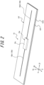
Fig. 2 is a perspective view illustrating an example of a communication device that can be use in a tire according to any one of the disclosed embodiments; and -
Fig. 3 is an exploded perspective view illustrating the disassembled communication device inFig. 2 . - Our tire can be suitable for use in any type of pneumatic tire, particularly a passenger vehicle pneumatic tire.
- By way of example, embodiments of our tire will be described below with reference to the drawings.
- Common members and portions appearing in the drawings have the same reference signs. In some of the drawings, the tire width direction is represented by a reference sign "WD", the tire radial direction is represented by a reference sign "RD", and the tire circumferential direction is represented by a reference sign "CD". In this description, the side near the tire inner cavity is referred to as "tire inner side" and the side far from the tire inner cavity from is referred to as "tire outer side".
-
Figs. 1 illustrates a tire 1 according to one of the disclosed embodiments.Fig. 1 is a cross-sectional view in a tire width direction illustrating a portion of a tire according to one of the disclosed embodiments (specifically, a portion of the tire on one side in relation to the tire equatorial plane CL). The tire 1 according to the embodiment inFig. 1 is a passenger vehicle pneumatic tire. - The tire 1 according to any one of the disclosed embodiments can be any type of a tire.
- The tire 1 includes a
tire body 1M and acommunication device 10. Thetire body 1M corresponds to a portion of the tire 1 excluding thecommunication device 10. - Hereinafter, unless otherwise specified, the positional relationship, dimensions, and the like of the components shall be determined under reference conditions where the tire 1 is installed on an applicable rim, set at a prescribed internal pressure, and unloaded. The width, in a tire width direction, of a contact patch that is contact with a road surface under conditions where the tire 1 is installed in an applicable rim, set at a prescribed internal pressure, and subjected to maximum load is referred to as the ground contact width of a tire, and an end of the contact patch in the tire width direction is referred to as ground contact end.
- In this description, the term "applicable rim" refers to a standard rim (Measuring Rim in STANDARDS MANUAL of ETRTO and Design Rim in YEAR BOOK of TRA) having an applicable size that is specified or will be specified in an industrial standard effective in the region where pneumatic tires are produced and used, such as JATMA YEAR BOOK of JATMA (the Japan Automobile Tyre Manufacturers Association) in Japan, STANDARDS MANUAL of ETRTO (The European Tyre and Rim Technical Organisation) in Europe, and YEAR BOOK of TRA (The Tire and Rim Association, Inc.) in the United States. However, with regard to sizes that are not specified in the above-mentioned industrial standards, the term "applicable rim" refers to a rim having a width corresponding to the bead width of a pneumatic tire. The "applicable rim" includes sizes that will be specified in the above-described industrial standards, in addition to currently specified sizes. Examples of "size that will be specified" can include a size specified as "FUTURE DEVELOPMENTS" in ETRTO 2013 version.
- In this description, the term "prescribed internal pressure" refers to an air pressure corresponding to the maximum load capacity of one wheel having an applicable size and ply rating that is specified or will be specified in an industrial standard such as the above-described JATMA YEAR BOOK (maximum air pressure). However, with regard to sizes not specified in the above-described industrial standards, the term "prescribed internal pressure" refers to an air pressure corresponding to the maximum load capacity defined for each vehicle in which the tire is installed (maximum air pressure). In this description, the term "maximum load" refers to a load corresponding to the maximum load capacity of a tire having an applicable size defined in the above-described industrial standard, or with regard to sizes not specified in the above-described industrial standards, refers to a load corresponding to the maximum load capacity specified for each vehicle in which a tire is installed.
- First of all, the
tire body 1M will be described. - As illustrated in
Fig. 1 , thetire body 1M includes thetread portion 1a, a pair ofsidewall portions 1b extending from both ends of thetread portion 1a in the tire width direction toward the tire radially inner side, and a pair ofbead portions 1c provided at an end, on the tire radially inner side, of each of thesidewall portions 1b. Thetread portion 1a is a tire widthwise portion, of thetire body 1M, between a pair of ground contact ends. Thetread portion 1a is a tire widthwise portion, of thetire body 1M, between a pair of ground contact ends. Thebead portion 1c is configured to be in contact with a rim on the tire radially inner side and the tire widthwise outer side when the tire 1 is installed on the rim. - The
tire body 1M includes a pair oftire side portions 1d extending from both ends of thetread portion 1a in the tire width direction toward the tire radially inner side. Thetire side portion 1d consists of asidewall portion 1b and abead portion 1c. - The
tire body 1M includes a pair ofbead cores 4a, a pair ofbead fillers 4b, acarcass 5, abelt 6, atread rubber 7, aside rubber 8, aninner liner 9, and a pair ofside reinforcing rubbers 2. - The
bead cores 4a are embedded in therespective bead portions 1c. Thebead core 4a includes a plurality of bead wire coated with a rubber. The bead wire is preferably made of metal (for example, steel). The bead wire can consist of, for example, monofilaments or twisted wires. The bead wire may be made of organic fibers or carbon fibers. - The
bead fillers 4b is positioned on the tire radially outer side relative to therespective bead cores 4a. Thebead filler 4b extends, in a tapered manner, toward the tire radially outer side. Thebead filler 4b is made of rubber, for example. - The
carcass 5 ranges between a pair ofbead cores 4a and extends to have a toroidal shape. Thecarcass 5 is constituted by one or more (in the embodiment inFig. 1 , two)carcass plies 5a. Each of thecarcass plies 5a includes one ormore carcass cords 5c, and acoating rubber 5r coating acarcass cord 5c (Fig. 1 ). Thecarcass cord 5c can be formed by monofilaments or twisted wires. - The
carcass cord 5c is preferably made of organic fibers such as polyester, nylon, rayon, and aramid. - The
carcass ply 5a includes a plymain body 5M between a pair ofbead cores 4a. Thecarcass ply 5a can further include ply turn-upportions 5T that extend from both ends of the plymain body 5M and are turned up around thebead cores 4a from the tire widthwise inner side toward the tire widthwise outer side. In this regard, thecarcass ply 5a may not include a ply turn-upportion 5 T. - The ply
main body 5M is positioned on the tire widthwise inner side relative to thebead filler 4b and thebead core 4a. The ply turn-upportion 5T is positioned on the tire widthwise outer side relative to thebead filler 4b and thebead core 4a. - The
carcass 5 is preferably of radial structure and may be of bias structure. - The
belt 6 is disposed on the tire radially outer side in relation to the crown portion of thecarcass 5. Thebelt 6 includes one or more belt layers 6a. Each of the belt layers 6a includes one or more belt cords and a coating rubber coating the belt cord. The belt cord can be formed of monofilaments or twisted wires. The belt cord can be made of metal (for example, steel) and can also be made of organic fibers such as polyester, nylon, rayon, and aramid. - At the
tread portion 1a, thetread rubber 7 is positioned on the tire radially outer side of thebelt 6. Thetread rubber 7 constitutes a tread surface, which is a surface on the tire radially outer side of thetread portion 1a. On the tread surface, a tread pattern is formed. - The
side rubber 8 is positioned on thesidewall portion 1b. Theside rubber 8 constitutes an outer surface, on the tire widthwise outer side, of thesidewall portion 1b. Theside rubber 8 is positioned on the tire widthwise outer side relative to thecarcass 5. Theside rubber 8 is positioned on the tire widthwise outer side relative to thebead filler 4b. Theside rubber 8 is formed to be integrated with thetread rubber 7. - The
inner liner 9 is disposed on the tire inner side of the carcass, and can be laminated, for example, on the tire inner side of thecarcass 5. Theinner liner 9 is made of a butyl-based rubber having low air permeability, for example. Examples of the butyl-based rubbers include butyl rubbers and halogenated butyl rubbers, which are derivatives of butyl rubbers. Theinner liner 9 is not limited to a butyl-based rubber and may be made of other rubber compositions, resins, or elastomers. - A
side reinforcing rubber 2 is disposed in thesidewall portion 1b. Theside reinforcing rubbers 2 are embedded in therespective sidewall portions 1b. Each of theside reinforcing rubbers 2 is disposed on the tire widthwise inner side of thecarcass 5. Each of theside reinforcing rubbers 2 is disposed on the tire widthwise outer side of theinner liner 9. Theside reinforcing rubber 2 has a crescent-shaped cross section, and in a cross-section in the tire width direction, the thickness of the crescent-shaped cross section gradually decrease toward each of the inner side and the outer side in the tire radial direction, and in addition, the crescent-shaped cross section is curved in a convex manner toward the tire widthwise outer side. In this way, the tire 1 is configured as a run flat tire. - The
side reinforcing rubber 2 is configured to reinforce thetire side portion 1d, and under conditions where the internal pressure of the tire 1 is low due to puncture and the like, contributes to supporting of vehicle body weight and suppress vertical deflection of the tire 1, and as a result, allows for running over a certain distance. - The
communication device 10 will be described below. - The
communication device 10 can be of any configuration as long as the configuration enables wireless communication between thecommunication device 10 and a predetermined external device (for example, a reader or reader/writer) located at the exterior of the tire 1, and thus, there is no particular limitation on the configuration of thecommunication device 10. - The
communication device 10 preferably includes a RF tag. The RF tag is also referred to as "RFID tag". The RF tag is preferably of passive type but can also be of active type. - The
communication device 10 can include an accelerometer detecting the acceleration of the tire 1, and an internal pressure sensor detecting the internal pressure of the tire 1, and the like, instead of or in addition to the RF tag. -
Figs. 2 and3 illustrates an example of thecommunication device 10. In this example, thecommunication device 10 includes a RF tag. In this example, thecommunication device 10 includes aRF tag 10e and acoating portion 10f. TheRF tag 10e includes anIC chip 10c and anantenna portion 10b. TheRF tag 10e is of passive type. - The
IC chip 10c operates, for example, by an induced electromotive force generated by a radio wave received by theantenna portion 10b. TheIC chip 10c includes a controller and a memory unit, for example. - The memory unit can store any information. For example, the memory unit can store identification information of the tire 1. The identification information of the tire 1 is, for example, identification information that is unique to the tire 1 and can identify each tire from the tires, such as the manufacturer of the tire 1, the manufacturing plant of the tire 1, and the date of manufacture of the tire 1. The memory unit can store tire historical information such as the running distance of a tire, the number of sudden braking, the number of sudden starting, and the number of sudden cornering situation. It is also possible that a sensor detecting, for example, a tire internal temperature, a tire internal pressure, a tire acceleration is provided in a tire inner cavity and the memory unit stores information detected by the sensors. In this case, the
RF tag 10e can wirelessly communicate with the sensor via theantenna portion 10b to obtain the information detected by the sensor. - The controller is configured to enables reading of information from the memory unit.
- The
antenna portion 10b includes a pair of antennas 10b1, 10b2. The pair of antenna 10b1, 10b2 are connected to opposite ends of theIC chip 10c, respectively. Theantenna portion 10b is configured to allow for transmitting information to and receiving information from the above-described predetermined external device located at the exterior of the tire 1. In the example inFigs. 2 and3 , each of theantennas 10b 1, 10b2 extends in a straight line, but each of the antennas 10b1, 10b2 may extend to have any shape such as waved shape. - The entirety of the
RF tag 10e is covered with thecoating portion 10f. Thecoating portion 10f is formed of a rubber or a resin, for example. - In this example, a
coating portion 10f includes a pair of sheet-shaped coating members 10f1, 10f2. The pair of coating members 10f1, 10f2 are stacked to sandwich theRF tag 10e between the pair of coating members 10f1, 10f2. The pair of coating members 10f1, 10f2 are preferably fixed to each other, for example, by adhesion. - In this regard, the
coating portion 10f may be constituted by one member. - In this example, the
coating portion 10f has a quadrilateral shape in a planar view. However, thecoating portion 10f can have any shape in a planar view. - The
communication device 10 may not include thecoating portion 10f, that is, can be constituted solely by theRF tag 10e. - By using the
antenna portion 10b, thecommunication device 10 configured as described above can receive information transmitted on a radio wave or a magnetic field from the above-described predetermined external device. Rectification (in the case of radio wave) or resonance (in the case of a magnetic field) generates power in theantenna portion 10b of thecommunication device 10, and the memory unit and the controller of theIC chip 10c perform a predetermined operation. For example, the controller reads information in the memory unit and returns (transmits) the information on a radio wave or a magnetic field from theantenna portion 10b to the above-described predetermined external device. The above-described predetermined external device receives the radio waves or the magnetic fields from thecommunication device 10. The above-described predetermined external device can retrieve the received information to obtain the information stored in the memory unit of theIC chip 10c in thecommunication device 10. - In connection with the matter described above, the
communication device 10 can have any configuration other than the configuration illustrated in this example. - The
communication device 10 can be provided with a longitudinal direction LD, a short-side direction SD, and a thickness direction TD. The longitudinal direction LD, the short-side direction SD, and the thickness direction TD are perpendicular to one another. - As illustrated in
Figs. 2 and3 , when thecommunication device 10 includes theRF tag 10e, the longitudinal direction LD of thecommunication device 10 is parallel to the extending direction of theantenna portion 10b. When theantennas 10b 1, 10b2 of theantenna portion 10b have waved shapes, the extending direction of theantenna portion 10b refers to the extending direction of the amplitude centerline of each of theantennas 10b 1, 10b2. In thecommunication device 10, when thecommunication device 10 includes thecoating portion 10f, the thickness direction TD of thecommunication device 10 refers to the thickness direction of thecoating portion 10f, and when thecommunication device 10 does not include thecoating portion 10f, refers to the thickness direction of theIC chip 10c. - The length of the
RF tag 10e in the longitudinal direction LD is preferably 20 mm or more or 50 mm or more, for example. The length of theRF tag 10e in the longitudinal direction LD is preferably 100 mm or less or 70 mm or less, for example. - The length of the
RF tag 10e in the short-side direction SD is preferably 10 mm or less or 8 mm or less, for example. - The length of the
RF tag 10e in the thickness direction TD is preferably 5 mm or less or 2 mm or less, for example. - When the
communication device 10 includes thecoating portion 10f, the length of thecommunication device 10 in the longitudinal direction LD is preferably 30 mm or more or 60 mm or more, for example. The length of theRF tag 10e in the longitudinal direction LD is preferably 110 mm or less or 80 mm or less, for example. - When the
communication device 10 includes thecoating portion 10f, the length of thecommunication device 10 in the short-side direction SD is preferably 20 mm or less or 15 mm or less, for example. - When the
communication device 10 includes thecoating portion 10f, the length of thecommunication device 10 in the thickness direction TD is preferably 6 mm or less or 3 mm or less, for example. - The thickness of each of the coating members 10f1, 10f2 of the
coating portion 10f is preferably 0.5 mm or more, for example. The thickness of each of the coating members 10f1, 10f2 of thecoating portion 10f is preferably 1 mm or less, for example. - In the embodiment in
Fig. 1 , thecommunication device 10 is embedded in thetire body 1M. Thecommunication device 10 can be disposed at any position in thetire body 1M. - In producing a tire 1, the raw tire constituting the
tire body 1M and thecommunication device 10 are accommodated in a mold for forming a tire and subjected to vulcanization molding. - In this regard, the
communication device 10 can be attached on an outer surface or inner surface of thetire body 1M, instead of being embedded in thetire body 1M. - As illustrated in
Fig. 1 , the tire 1 (specifically, thetire body 1M) includes one or more low-thermal-conductivity members 3 having a lower thermal conductivity than that of theside reinforcing rubber 2. The one or more low-thermal-conductivity members 3 are positioned between theside reinforcing rubber 2 and thecommunication device 10. - In the embodiment in
Fig. 1 , thecarcass cords 5c (cords) of thecarcass 5 constitute the respective low-thermal-conductivity members 3. In other words, each of the low-thermal-conductivity members 3 is constituted by thecarcass cord 5c (cord) of thecarcass 5. In order for thecarcass cord 5c to constitute the low-thermal-conductivity member 3 (and hence, have a lower thermal conductivity than that of the side reinforcing rubber 2), for example, thecarcass cord 5c may be made of organic fibers such as polyester, nylon, rayon, and aramid. - When the low-thermal-
conductivity member 3 is constituted by a cord, the "thermal conductivity" of the low-thermal-conductivity member 3 shall be measured in accordance with JIS R 1611:2010. When the low-thermal-conductivity member 3 is constituted by a member other than the cord (such as a rubber member), the "thermal conductivity" of the low-thermal-conductivity member 3 shall be measured in accordance with JIS A 1412-2: 1999. The "thermal conductivity" of the rubber member (theside reinforcing rubber 2, thecoating rubber 5r of thecarcass 5, thetread rubber 7, theside rubber 8, andcoating portion 10f of the communication device 10) shall be measured in accordance with JIS A 1412-2:1999. - During the running in a state where the internal pressure of the tire 1 is low due to puncture and the like (during the run flat running), heat tends to generate from the
side reinforcing rubber 2. However, in this embodiment, the low-thermal-conductivity member 3 is positioned between theside reinforcing rubber 2 and thecommunication device 10. Therefore, the low-thermal-conductivity member 3 positioned between theside reinforcing rubber 2 and thecommunication device 10 can block heat from theside reinforcing rubber 2 to suppress for the heat to be transferred to thecommunication device 10. This can suppress the damage to thecommunication device 10 by heat. - By suppressing the damage to the
communication device 10, even if thetire body 1M is subjected to failure due to puncture and the like, loss of the communication function of thecommunication device 10 can be suppressed. From a standpoint of managing the tire 1, it is desirable that thecommunication device 10 have a communication function even after the tire 1 is dismounted from the vehicle for disposal due to failure and the like. - In addition to or instead of the matter that the
carcass cords 5c (cord) of thecarcass 5 constitute the respective low-thermal-conductivity members 3, cords other than thecarcass cord 5c can constitute the low-thermal-conductivity member 3 and any members other than the cord can also constitute low-thermal-conductivity member 3. For example, thecoating rubber 5r of thecarcass 5 may constitute the low-thermal-conductivity member 3. - When the low-thermal-
conductivity member 3 is constituted by the member other than the rubber member (cord such as thecarcass cord 5c), the thermal conductivity of the low-thermal-conductivity member 3 is preferably lower than each thermal conductivity of all of the rubber members (such as thetread rubber 7, theside rubber 8, and thecoating portion 10f of the communication device 10) constituting the tire 1. - When the low-thermal-
conductivity member 3 is constituted by the rubber member (for example, thecoating rubber 5r of the carcass 5), the thermal conductivity of the low-thermal-conductivity member 3 is preferably lower than each thermal conductivity of all of other rubber members (such as thetread rubber 7, theside rubber 8, and thecoating portion 10f of the communication device 10) constituting the tire 1. - When the low-thermal-
conductivity member 3 is constituted by a cord (for example,carcass cord 5c), the end count of the cord is preferably 20 or more per 50 mm. As a result, the low-thermal-conductivity member 3 can effectively block heat from theside reinforcing rubber 2 to suppress the damage to thecommunication device 10 by heat further. - The end count of the above-described cord is preferably 65 or less per 50 mm.
- As illustrated in the embodiment in
Fig. 1 , one or more low-thermal-conductivity members 3 are preferably positioned between theside reinforcing rubber 2 and thecommunication device 10 in the tire width direction. As illustrated in the embodiment inFig. 1 , thecommunication device 10 can be positioned on the tire widthwise outer side relative to theside reinforcing rubber 2, or can be positioned on the tire widthwise inner side relative to theside reinforcing rubber 2. - As illustrated in the embodiment in
Fig. 1 , thecommunication device 10 is preferably positioned between theside rubber 8 and the low-thermal-conductivity member 3. Specifically, as illustrated in the embodiment inFig. 1 , thecommunication device 10 is preferably positioned between theside rubber 8 and the one or more low-thermal-conductivity members 3 in the tire width direction. One or more low-thermal-conductivity members 3 are positioned on the tire widthwise inner side relative to theside rubber 8. - The
side rubber 8 is positioned on the tire radially outermost side, and therefore has high heat dissipation performance. Accordingly, as a result of the matter that thecommunication device 10 is positioned between theside rubber 8 and the low-thermal-conductivity member 3, the amount of heat applied to thecommunication device 10 by heat dissipation function of theside rubber 8 can be further reduced, and in consequence, the damage to thecommunication device 10 by heat can be further suppressed. - In this case, the
communication device 10 is preferably in contact with theside rubber 8, as illustrated inFig. 1 . - As illustrated in
Fig. 1 , thecommunication device 10 is preferably embedded in thetire side portion 1d of the tire 1. - In general, the metal may weaken a radio wave between the
communication device 10 and the above-described predetermined external device (for example, a reader or reader/writer) to reduce communication performance regarding communication between thecommunication device 10 and the above-described predetermined external device, and in consequence, the communication distance between thecommunication device 10 and the above-described predetermined external device may be shortened. In thetire body 1M, a metal (for example, steel) can be used in thebelt 6, thebead core 4a, and the like. In addition, thetire side portion 1d generally has less amount of metal than thetread portion 1a. Therefore, by disposing thecommunication device 10 in thetire side portion 1d, in comparison to the case where thecommunication device 10 is disposed in thetread portion 1a, the communication performance can be improved and the communication distance between thecommunication device 10 and the above-described predetermined external device can be lengthened. - The
communication device 10 is preferably embedded in a portion of thetire side portion 1d of thetire body 1M on the tire widthwise outer side relative to thecarcass 5. - The
communication device 10 is preferably oriented in such a way that the thickness direction TD of thecommunication device 10 is substantially along the tire width direction (Fig. 1 ). - The direction toward which the
communication device 10 is oriented (the orientation of the communication device 10) is arbitrary. However, from a standpoint of, for example, the durability of thecommunication device 10, thecommunication device 10 is preferably oriented in such a way that the longitudinal direction LD of thecommunication device 10 is substantially along the tire circumferential direction, as illustrated in the embodiment inFig. 1 . In this regard, thecommunication device 10 can be oriented in such a way that the short-side direction SD of thecommunication device 10 is substantially along the tire circumferential direction. - As illustrated in the embodiment in
Fig. 1 , thecommunication device 10 is preferably disposed in thesidewall portion 1b. Thesidewall portion 1b generally tends to have less amount of metal than thebead portion 1c. Therefore, by disposing thecommunication device 10 in thesidewall portion 1b, in comparison to the case where thecommunication device 10 is disposed in thebead portion 1c, the communication performance can be improved and the communication distance between thecommunication device 10 and the above-described predetermined external device can be lengthened. - As illustrated in
Fig. 1 , the tire radiallyouter end 10u of the communication device 10 (more preferably, the entirety of the communication device 10) is preferably located on the tire radially outer side relative to the tire radially outer end of thebead core 4a. More preferably, the tire radiallyouter end 10u is located on the tire radially outer side relative to the tire radial center of thebead filler 4b. For example, the tire radiallyouter end 10u is preferably located on the tire radially outer side relative to the tire radially outer end 4bu of thebead filler 4b. - The above-described configuration is particularly preferable when the tire 1 is a passenger vehicle pneumatic tire.
- In a case where the
communication device 10 is disposed in thesidewall portion 1b as described above, as illustrated in the example inFig. 1 , the tire radiallyouter end 10u of thecommunication device 10 is preferably positioned on the tire radially inner side relative to the tire radiallyouter end 5e of the ply turn-upportion 5T of thecarcass 5. As a result, the communication performance can be improved and the communication distance between thecommunication device 10 and the above-described predetermined external device can be lengthened. In addition, thecommunication device 10 can be disposed in a portion of thetire body 1M with relatively small strain, for example, in rolling of the tire 1. Therefore, the durability of thecommunication device 10 and hence the tire 1 can be improved - The tire radial distance between the tire radially
outer end 10u of thecommunication device 10 and the tire radiallyouter end 5e of the ply turn-upportion 5T of thecarcass 5 is preferably 3 to 30 mm, and more preferably 5 to 15 mm. - The above-described configuration is particularly preferable when the tire 1 is a passenger vehicle pneumatic tire.
- As illustrated in the example in
Fig. 1 , the tire radiallyouter end 5e of the ply turn-upportion 5T of thecarcass 5 is preferably positioned on the tire radially outer side relative to the tire radially outer end 4bu of thebead filler 4b. In this regard, the tire radiallyouter end 5e of the ply turn-upportion 5T of thecarcass 5 can be positioned at the same tire radial position as that of the tire radially outer end of thebead filler 4b or can be positioned on the tire radially inner side relative to the tire radial position of the tire radially outer end of thebead filler 4b. - The tire radially
outer end 5e of the ply turn-upportion 5T of thecarcass 5 can be positioned on the tire radially outer side relative to the tire maximum width position of thetire body 1M, and can also be positioned at the same tire radial position as that of the tire maximum width position of thetire body 1M, and can also be positioned on the tire radially inner side relative to the tire maximum width position of thetire body 1M. The term "tire maximum width position of thetire body 1M" refers to a tire radial position at which the dimension of thetire body 1M in the tire width direction becomes maximum. - As illustrated in the example in
Fig. 1 , thecommunication device 10 is preferably in contact with a surface on the tire widthwise outer side of thecarcass 5, and more preferably in contact with a surface on the tire widthwise outer side of the ply turn-upportion 5T of thecarcass 5. - The above-described configuration is particularly preferable when the tire 1 is a passenger vehicle pneumatic tire.
- The tire rubber composition described in detail below is preferably used in at least a portion of the rubber constituting the tire 1 (for example, at least one of the
side rubber 8, thetread rubber 7, thecoating rubber 5r of thecarcass ply 5a, the squeegee rubber between the carcass plies 5a, the coating rubber of the belt layer 6a, and thebead filler 4b). By using the tire rubber composition, it is possible to achieve a tire 1 that has low rolling resistance and high durability and in which increase in the electric resistance is suppressed without degradation of reinforcing ability and durability performance. - In particular, when the tire rubber composition is used in the
side rubber 8, lowered loss can be achieved, and in consequence, the rolling resistance can be reduced. In addition, the amount of heat generated from theside rubber 8 due to the deformation in the rolling is reduced. As a result, the damage to thecommunication device 10 by heat can be further suppressed accordingly. - The above-described tire rubber composition is obtained by blending 35 to 50 parts by mass of carbon black with a nitrogen adsorption specific surface area (N2SA) of 30 to 43 m2/g and 5 parts by mass or less of oil, based on 100 parts by mass of rubber component including 20 to 40 parts by mass of styrene butadiene rubber and 60 to 80 parts by mass of natural rubber.
- Examples of the rubber components used in the above-described tire rubber composition at least include a styrene butadiene rubber (SBR) and a natural rubber (NR).
- The content of styrene butadiene rubber is preferably 20 to 40 parts by mass based on 100 parts by mass of rubber component. By setting the content of the styrene butadiene rubber to be 20 parts by mass or more, low-strain crack propagation resistance can be improved to enhance the processability of the unvulcanized rubber. By setting the content of the styrene butadiene rubber to be 40 parts by mass or less, further lowered loss can be achieved.
- Examples of styrene butadiene rubbers that can be used include solution-polymerized styrene butadiene rubbers, emulsion-polymerized styrene butadiene rubbers, and modified styrene butadiene rubbers.
- The content of the natural rubber is preferably 60 to 80 parts by mass based on 100 parts by mass of rubber component. By setting the content of the natural rubber to be 60 parts by mass or more, the high-strain crack propagation resistance can be improved. By setting the content of the natural rubber to be 80 parts by mass or less, the processability of the unvulcanized rubber can be improved and the costs can be reduced.
- Examples of the natural rubber include natural rubbers used in tire industry, such as
RSS# 3, TSR20, and SIR20. - In addition to the natural rubbers (NR) and styrene butadiene rubbers (SBR) described above, if required, it is possible to use at least one of butadiene rubbers (BR), isoprene rubbers (IR), butyl rubbers (IIR), halogenated butyl rubbers, chloroprene rubbers (CR), acrylonitrile-butadiene rubbers (NBR), ethylene-propylene-diene terpolymers (EPDM).
- As a carbon black used in the above-described tire rubber composition, a carbon black with a nitrogen adsorption specific surface area (N2SA, measured in accordance with JIS K 6217-2:2001) of 30 to 43 m2/g is used. The reason why this nitrogen adsorption specific surface area (N2SA) of the carbon black is limited to the above-described range is because the dispersibility of carbon black is improved by using a carbon black with a large particle size. Preferably, the above-described nitrogen adsorption specific surface area (N2SA) is 33 to 40 m2/g.
- As a carbon black having such properties, it is possible to use FEF, GPF, SRF, and the like.
- The content of the above-described carbon black is preferably 35 parts by mass or more based on 100 parts by mass of rubber component. As a result, the mechanical strength of the rubber can be ensured.
- The content of the above-described carbon black is preferably 50 parts by mass or less based on 100 parts by mass of rubber component. This allows for lowered loss and also reduces the amount of heat generated from the above-described tire rubber composition due to the deformation in the rolling. As a result, the damage to the
communication device 10 by heat can be further suppressed accordingly. - Examples of oils used in the above-described tire rubber composition include at least one oil selected from paraffin-based oils, naphthene-based oils, aromatic oils and aromatic-compound-based oils, and these oils can be commercially available products.
- For example, as a paraffin-based oil, it is possible to use commercially available products such as a paraffin-based oil under the trade name "Super Oil Y22" manufactured by JX Nippon Oil & Energy Corporation. The naphthene-based oil can be hydrogenated or unhydrogenated. As a naphthene-based oil, it is possible to use commercially available products such as "straight asphalt-containing naphthene-based oil manufactured by SANKYO YUKA KOGYO K.K." under the trade name "A/OMIX".
- The content of the above-described oil is 5 parts by mass or less (including 0 parts by mass) based on 100 parts by mass of rubber component.
- The mechanical strength of the rubber can be improved by setting the content of the above-described oil to be 5 parts by mass or less. Even in the case where the above-described oil is not included (0 parts by mass), a compounding agent such as a carbon black can be sufficiently dispersed to obtain necessary rubber properties. In particular, the content of the oil is preferably 0 to 3 parts by mass.
- For the purpose of providing additional electrical conductivity to decrease the electric resistance further and for the purpose of improving the durability performance further, it is preferable that the above-described tire rubber composition further include at least one of Ketjen black and a carbon nanotube (CNT).
- As carbon nanotubes (CNT) that can be used, there may be mentioned graphene sheets in the form of rounded rods or in the form of threads, vapor grown carbon fibers (VGCF), and the like and C100 (manufactured by Arkemasya) or NC7000 (manufactured by Nanocyl), which are commercially available products of the foregoing, is usable. These carbon nanotubes (CNT) provides additional electrical conductivity, and unlike the above-described carbon black, interacts less with the rubber, resulting in lower elastic modulus the high-strain region of the high strain curve of the stress-strain curve and an increased elongation at break (Eb). Accordingly, when Eb of the rubber in crack propagation is high, relaxation of crack tip energy occurs to improve the crack propagation resistance.
- As Ketjen black, it is possible to use various grades of Ketjen black containing hollow shell-shaped particles and having high electrical conductivity. Examples of Ketjen black that can be used include at least one of Ketjen black EC300J [granulated] manufactured by Lion Corporation, Ketjen black EC600JD [granulated], CARBON ECP [powder of Ketjen black EC300J], CARBON ECP600JD [powder of Ketjen black EC600JD], and Lionite.
- The total compounding amount of Ketjen black and the carbon nanotube is preferably 0.1 to 6 parts by mass, more preferably 1.0 to 5 parts by mass based on 100 parts by mass of rubber component.
- By setting the total compounding amount of Ketjen black and the carbon nanotube to be 0.1 parts by mass or more, a rubber compound can be provided with electrical conductivity. By setting such total compounding amount to be 6 parts by mass or less, decrease in the low loss property of the rubber can be prevented.
- In the above-described tire rubber composition, a carbon black, Ketjen black and a carbon nanotube with a nitrogen adsorption specific surface area (N2SA) satisfying the above-described range are used as fillers. However, for the purpose of providing better electrical conductivity and for the purpose of further improving the crack propagation resistance to improve the durability performance further, it is preferable that at least one of Ketjen black and a carbon nanotube be blended in an amount of preferably 2 to 15%, more preferably 2.5 to 12.5%, by mass of the fillers.
- As fillers other than carbon black, Ketjen black, carbon nanotube described above, it is possible to use silica, clay, talc, calcium carbonate, and the like.
- In addition to the above-described components, other components can be appropriately selected according to the purpose or the need and blended into the above-described tire rubber composition. Examples of the other components include vulcanizing agents such as sulfur, vulcanization accelerators such as thiazole-based and sulfenamide-based vulcanization accelerators, vulcanizing co-agents, zinc oxide (zinc white), stearic acid, age resisters, antioxidants, antiozonants, colorants, lubricants, silane coupling agent, foaming agents, additives such as foaming aids, as well as a variety of known compounding ingredients ordinally used in the tire industry. The other components described above can be commercially available products.
- The above-described tire rubber composition can be prepared by blending a carbon black, an oil, and other components having the above-described properties into the above-described rubber component, and in addition, kneading Ketjen black, carbon nanotube, zinc white, stearic acid, an age resister, sulfur, a vulcanization accelerator, and additives appropriately selected according to the purpose or the need into the rubber component.
- There is no particular limitation regarding the conditions of kneading described above. Conditions such as the capacity of kneader, the rotational velocity of the rotor, the ram pressure, the kneading temperature, the kneading time, and the type of the kneader can be appropriately selected according to the purpose. Examples of such a kneader include Banbury mixers, Intermix, kneaders, and rolls ordinally used in kneading of a rubber composition.
- In the case where the compounding amount of the styrene butadiene rubber in the above-described tire rubber composition is A parts by mass and the compounding amount of the natural rubber is B parts by mass, a rubber composition in which a carbon black with a nitrogen adsorption specific surface area (N2SA) of 30 to 43 m2/g included in the above-described tire rubber composition is blended in an amount of A * 100 / (A + B) (% by mass) based on A parts by mass of styrene butadiene rubber is taken as rubber composition X. In addition, a rubber composition in which a carbon black with a nitrogen adsorption specific surface area (N2SA) of 30 to 43 m2/g included in the above-described tire rubber composition is blended in an amount of B * 100 / (A + B) (% by mass) based on B parts by mass of natural rubber is taken as rubber composition Y. Also, the above-described tire rubber composition is taken as rubber composition Z. In this case, when moduli at 50% elongation of the rubber compositions X, Y, and Z are taken as Mdx, Mdy, and Mdz (MPa), respectively, it is preferable that Mdx, Mdy, and Mdz satisfy the formula (I):

- When the tire rubber composition satisfies the formula (I), increase in the electric resistance is further suppressed without degradation of reinforcing ability and durability performance, the rolling resistance is further reduced, and in addition, higher durability is achieved.
- As described above, the above-described tire rubber composition is applied to at least one member selected from the ply coating rubber of the carcass ply, the belt coating rubber of the belt layer, the squeegee rubber between the carcass plies, the cushion rubber, the belt under cushion, and the bead filler rubber. The tire rubber composition is preferably applied to a ply coating rubber because the amount of the rubber used for the ply coating rubber is large and this has a significant influence on the loss property of the entirety of the tire, and also, the ply coating rubber is positioned at the center of a conductive path from the trim to the tread. As a result, a pneumatic tire establishing a balance between lowered loss, crash resistance/reinforcing ability, electrical conductivity can be achieved.
- By using the tire rubber composition configured as described above, the durability performance in high-strain region is improved by setting the amount of natural rubber (NR) to be in a specific range, and also, the low-strain durability is improved without deterioration of lowered loss by setting the amount of styrene butadiene rubber (SBR) to be in a specific range. In addition, the lowered loss of the rubber is achieved by using a carbon black with a nitrogen adsorption specific surface area (N2SA) limited to the above-described range, and also, the reinforcing ability is improved by setting the amount of the oil to be in a predetermined amount or less. Therefore, the tire rubber composition configured as described above can be helpful to provide a tire that has low rolling resistance and high durability and also has reinforcing ability and durability performance equivalent to those of conventional tire, and in the tire, increase in the electric resistance is suppressed.
- In addition, by inclusion of 0.1 to 6 parts by mass of at least one of Ketjen black and a carbon nanotube, a tire rubber composition having better electrical conductivity without deterioration of dispersion defect and low loss property is provided. It is known that conductive materials generally have poor dispersibility, deteriorates low loss property, and weakly interact with the rubbers. However, as a result of studying the types and the number of parts of the conductive materials, we can provide additional electrical conductivity, without deterioration of dispersion defect and lowered loss, by blending at least one of Ketjen black and a carbon nanotube at a specific number of parts. In addition, by utilizing low reinforcing ability of the above-mentioned conductive materials, the tire rubber composition has better durability performance.
- In addition, the above-described tire rubber composition in which at least one of Ketjen black and a carbon nanotube is blended in an amount of 2 to 15% by mass of the fillers is advantageous because the tire rubber composition still has the above-described lowered loss and reinforcing ability, and yet provides additional electrical conductivity and better durability performance.
- Our tire can be suitable for use in any type of pneumatic tire, particularly a passenger vehicle pneumatic tire.
-
- 1
- Tire
- 1M
- Tire body
- 1a
- Tread portion
- 1b
- Sidewall portion
- 1c
- Bead portion
- 1d
- Tire side portion
- 2
- Side reinforcing rubber
- 3
- Low thermal conductive member
- 4a
- Bead core
- 4b
- Bead filler
- 4bu
- Tire radially outer end of bead filler
- 5
- Carcass
- 5a
- Carcass ply
- 5c
- Carcass cord (cord)
- 5r
- Coating rubber
- 5M
- Ply main body
- 5T
- Ply turn-up portion
- 5e
- Tire radially outer end of ply turn-up portion of carcass
- 6
- Belt
- 6a
- Belt layer
- 7
- Tread rubber
- 8
- Side rubber
- 9
- Inner liner
- 10
- Communication device
- 10e
- RF tag
- 10b
- Antenna portion
- 10b1, 10b2
- Antennas
- 10f
- Coating portion
- 10f1, 10f2
- Coating members
- 10c
- IC chip
- 10u
- Tire radially outer end of communication device
- CL
- Tire equatorial plane
- WD
- Tire width direction
- RD
- Tire radial direction
- CD
- Tire circumferential direction
- LD
- Longitudinal direction of communication device
- SD
- Short-side direction of communication device
- TD
- Thickness direction of communication device
Claims (5)
- A tire, comprising:a side-reinforcing rubber having a crescent-shaped cross section disposed in a side wall portion of the tire;a low-thermal-conductivity member having a lower thermal conductivity than that of the side reinforcing rubber; anda communication device, whereinthe low-thermal-conductivity member is positioned between the side reinforcing rubber and the communication device.
- The tire according to claim 1, wherein
the low-thermal-conductivity member is constituted by a cord. - The tire according to claim 1 or 2, wherein
the communication device is positioned between a side rubber of the tire and the low-thermal-conductivity member. - The tire according to any one of claims 1 to 3, wherein
a content of carbon black in the side rubber of the tire is 50 parts by mass or less based on 100 parts by mass of rubber component. - The tire according to any one of claims 1 to 4, wherein
the communication device includes a RF tag.
Applications Claiming Priority (2)
| Application Number | Priority Date | Filing Date | Title |
|---|---|---|---|
| JP2021199587A JP2023085093A (en) | 2021-12-08 | 2021-12-08 | tire |
| PCT/JP2022/020441 WO2023105816A1 (en) | 2021-12-08 | 2022-05-16 | Tire |
Publications (3)
| Publication Number | Publication Date |
|---|---|
| EP4446128A1 true EP4446128A1 (en) | 2024-10-16 |
| EP4446128A4 EP4446128A4 (en) | 2024-12-25 |
| EP4446128B1 EP4446128B1 (en) | 2025-12-31 |
Family
ID=86730008
Family Applications (1)
| Application Number | Title | Priority Date | Filing Date |
|---|---|---|---|
| EP22903754.4A Active EP4446128B1 (en) | 2021-12-08 | 2022-05-16 | TIRES |
Country Status (5)
| Country | Link |
|---|---|
| US (1) | US20250001814A1 (en) |
| EP (1) | EP4446128B1 (en) |
| JP (1) | JP2023085093A (en) |
| CN (1) | CN118354917A (en) |
| WO (1) | WO2023105816A1 (en) |
Families Citing this family (2)
| Publication number | Priority date | Publication date | Assignee | Title |
|---|---|---|---|---|
| JP2025093159A (en) * | 2023-12-11 | 2025-06-23 | 株式会社ブリヂストン | tire |
| JP2025093160A (en) * | 2023-12-11 | 2025-06-23 | 株式会社ブリヂストン | tire |
Family Cites Families (18)
| Publication number | Priority date | Publication date | Assignee | Title |
|---|---|---|---|---|
| JP4397533B2 (en) * | 2001-01-15 | 2010-01-13 | 横浜ゴム株式会社 | Tire transponder |
| KR101095290B1 (en) * | 2003-04-15 | 2011-12-16 | 요코하마 고무 가부시키가이샤 | Tire alarm device |
| JP4384885B2 (en) * | 2003-09-04 | 2009-12-16 | 株式会社ブリヂストン | Tire with transponder |
| DE102005018155A1 (en) * | 2005-04-20 | 2006-10-26 | Continental Aktiengesellschaft | Vehicle pneumatic tire, has heat bridge with material strip and arranged between rim strip and lower area of side wall in base area of tire, where heat conductivity of heat bridge is higher than rubber material |
| JP4957356B2 (en) * | 2007-04-26 | 2012-06-20 | 横浜ゴム株式会社 | Pneumatic tire for run flat |
| JP5204577B2 (en) * | 2008-07-30 | 2013-06-05 | 住友ゴム工業株式会社 | Run flat tire |
| JP5462468B2 (en) * | 2008-11-04 | 2014-04-02 | 住友ゴム工業株式会社 | Run flat tire |
| JP5222250B2 (en) * | 2009-08-20 | 2013-06-26 | 住友ゴム工業株式会社 | Run flat tire |
| JP5395739B2 (en) * | 2010-05-18 | 2014-01-22 | 住友ゴム工業株式会社 | vehicle |
| JP5589015B2 (en) * | 2012-02-27 | 2014-09-10 | 住友ゴム工業株式会社 | Pneumatic tire |
| DE102013103077A1 (en) * | 2013-03-26 | 2014-10-02 | Continental Reifen Deutschland Gmbh | Vehicle tires |
| JP2015105063A (en) * | 2013-12-02 | 2015-06-08 | 横浜ゴム株式会社 | Pneumatic tire |
| JP6467950B2 (en) * | 2015-01-29 | 2019-02-13 | 横浜ゴム株式会社 | Pneumatic tire |
| FR3067975B1 (en) * | 2017-06-22 | 2019-07-26 | Compagnie Generale Des Etablissements Michelin | PNEUMATIC ADAPTED FOR FLAT ROLLING EQUIPPED WITH AN ELECTRONIC MEMBER |
| FR3067976B1 (en) * | 2017-06-22 | 2019-07-26 | Compagnie Generale Des Etablissements Michelin | PNEUMATIC ADAPTED FOR FLAT ROLLING EQUIPPED WITH AN ELECTRONIC MEMBER |
| EP3677450B1 (en) * | 2017-09-12 | 2022-10-12 | Sumitomo Rubber Industries, Ltd. | Pneumatic tire |
| JP7484187B2 (en) * | 2020-01-29 | 2024-05-16 | 住友ゴム工業株式会社 | Safety Tires |
| JP7712194B2 (en) * | 2021-12-08 | 2025-07-23 | 株式会社ブリヂストン | tire |
-
2021
- 2021-12-08 JP JP2021199587A patent/JP2023085093A/en active Pending
-
2022
- 2022-05-16 WO PCT/JP2022/020441 patent/WO2023105816A1/en not_active Ceased
- 2022-05-16 EP EP22903754.4A patent/EP4446128B1/en active Active
- 2022-05-16 CN CN202280080661.2A patent/CN118354917A/en active Pending
- 2022-05-16 US US18/709,809 patent/US20250001814A1/en active Pending
Also Published As
| Publication number | Publication date |
|---|---|
| CN118354917A (en) | 2024-07-16 |
| EP4446128A4 (en) | 2024-12-25 |
| US20250001814A1 (en) | 2025-01-02 |
| WO2023105816A1 (en) | 2023-06-15 |
| JP2023085093A (en) | 2023-06-20 |
| EP4446128B1 (en) | 2025-12-31 |
Similar Documents
| Publication | Publication Date | Title |
|---|---|---|
| EP2239154B1 (en) | Side part reinforcing layer and run-flat tire | |
| EP3677452A1 (en) | Pneumatic tire | |
| EP3677448B1 (en) | Pneumatic tire | |
| EP3677451A1 (en) | Pneumatic tire | |
| EP4446128B1 (en) | TIRES | |
| JP7484187B2 (en) | Safety Tires | |
| WO2006098110A1 (en) | Pneumatic tire | |
| EP1990218B1 (en) | Run flat tire | |
| JP7722876B2 (en) | Tire and tire manufacturing method | |
| EP4446132A1 (en) | Tire | |
| EP4446135A1 (en) | Tire | |
| EP4446133A1 (en) | Tire | |
| CN117734352A (en) | Pneumatic tire | |
| US20250282180A1 (en) | Heavy duty tire | |
| JP2018016201A (en) | Run flat tire | |
| EP4491418A1 (en) | Pneumatic tire | |
| JP2024135182A (en) | Pneumatic tire | |
| JP2020104752A (en) | Pneumatic tire |
Legal Events
| Date | Code | Title | Description |
|---|---|---|---|
| STAA | Information on the status of an ep patent application or granted ep patent |
Free format text: STATUS: THE INTERNATIONAL PUBLICATION HAS BEEN MADE |
|
| PUAI | Public reference made under article 153(3) epc to a published international application that has entered the european phase |
Free format text: ORIGINAL CODE: 0009012 |
|
| STAA | Information on the status of an ep patent application or granted ep patent |
Free format text: STATUS: REQUEST FOR EXAMINATION WAS MADE |
|
| 17P | Request for examination filed |
Effective date: 20240514 |
|
| AK | Designated contracting states |
Kind code of ref document: A1 Designated state(s): AL AT BE BG CH CY CZ DE DK EE ES FI FR GB GR HR HU IE IS IT LI LT LU LV MC MK MT NL NO PL PT RO RS SE SI SK SM TR |
|
| REG | Reference to a national code |
Ref legal event code: R079 Ipc: B60C0019000000 Ref country code: DE Ref legal event code: R079 Ref document number: 602022028180 Country of ref document: DE Free format text: PREVIOUS MAIN CLASS: B60C0001000000 Ipc: B60C0019000000 |
|
| A4 | Supplementary search report drawn up and despatched |
Effective date: 20241126 |
|
| RIC1 | Information provided on ipc code assigned before grant |
Ipc: B60C 13/00 20060101ALN20241121BHEP Ipc: B60C 1/00 20060101ALN20241121BHEP Ipc: B60C 9/02 20060101ALI20241121BHEP Ipc: B60C 17/00 20060101ALI20241121BHEP Ipc: B60C 19/00 20060101AFI20241121BHEP |
|
| DAV | Request for validation of the european patent (deleted) | ||
| DAX | Request for extension of the european patent (deleted) | ||
| GRAP | Despatch of communication of intention to grant a patent |
Free format text: ORIGINAL CODE: EPIDOSNIGR1 |
|
| STAA | Information on the status of an ep patent application or granted ep patent |
Free format text: STATUS: GRANT OF PATENT IS INTENDED |
|
| RIC1 | Information provided on ipc code assigned before grant |
Ipc: B60C 19/00 20060101AFI20250722BHEP Ipc: B60C 17/00 20060101ALI20250722BHEP Ipc: B60C 9/02 20060101ALI20250722BHEP Ipc: B60C 1/00 20060101ALN20250722BHEP Ipc: B60C 13/00 20060101ALN20250722BHEP |
|
| INTG | Intention to grant announced |
Effective date: 20250820 |
|
| RIN1 | Information on inventor provided before grant (corrected) |
Inventor name: ONO, TAKATOSHI |
|
| P01 | Opt-out of the competence of the unified patent court (upc) registered |
Free format text: CASE NUMBER: UPC_APP_9422_4446128/2025 Effective date: 20251009 |
|
| GRAS | Grant fee paid |
Free format text: ORIGINAL CODE: EPIDOSNIGR3 |
|
| GRAA | (expected) grant |
Free format text: ORIGINAL CODE: 0009210 |
|
| STAA | Information on the status of an ep patent application or granted ep patent |
Free format text: STATUS: THE PATENT HAS BEEN GRANTED |
|
| AK | Designated contracting states |
Kind code of ref document: B1 Designated state(s): AL AT BE BG CH CY CZ DE DK EE ES FI FR GB GR HR HU IE IS IT LI LT LU LV MC MK MT NL NO PL PT RO RS SE SI SK SM TR |
|
| REG | Reference to a national code |
Ref country code: CH Ref legal event code: F10 Free format text: ST27 STATUS EVENT CODE: U-0-0-F10-F00 (AS PROVIDED BY THE NATIONAL OFFICE) Effective date: 20251231 Ref country code: GB Ref legal event code: FG4D |
|
| REG | Reference to a national code |
Ref country code: DE Ref legal event code: R096 Ref document number: 602022028180 Country of ref document: DE |
|
| REG | Reference to a national code |
Ref country code: IE Ref legal event code: FG4D |
|
| REG | Reference to a national code |
Ref country code: LT Ref legal event code: MG9D |
|
| PG25 | Lapsed in a contracting state [announced via postgrant information from national office to epo] |
Ref country code: NO Free format text: LAPSE BECAUSE OF FAILURE TO SUBMIT A TRANSLATION OF THE DESCRIPTION OR TO PAY THE FEE WITHIN THE PRESCRIBED TIME-LIMIT Effective date: 20260331 |
|
| PG25 | Lapsed in a contracting state [announced via postgrant information from national office to epo] |
Ref country code: FI Free format text: LAPSE BECAUSE OF FAILURE TO SUBMIT A TRANSLATION OF THE DESCRIPTION OR TO PAY THE FEE WITHIN THE PRESCRIBED TIME-LIMIT Effective date: 20251231 Ref country code: HR Free format text: LAPSE BECAUSE OF FAILURE TO SUBMIT A TRANSLATION OF THE DESCRIPTION OR TO PAY THE FEE WITHIN THE PRESCRIBED TIME-LIMIT Effective date: 20251231 |
|
| PG25 | Lapsed in a contracting state [announced via postgrant information from national office to epo] |
Ref country code: RS Free format text: LAPSE BECAUSE OF FAILURE TO SUBMIT A TRANSLATION OF THE DESCRIPTION OR TO PAY THE FEE WITHIN THE PRESCRIBED TIME-LIMIT Effective date: 20260331 |
|
| PG25 | Lapsed in a contracting state [announced via postgrant information from national office to epo] |
Ref country code: LV Free format text: LAPSE BECAUSE OF FAILURE TO SUBMIT A TRANSLATION OF THE DESCRIPTION OR TO PAY THE FEE WITHIN THE PRESCRIBED TIME-LIMIT Effective date: 20251231 |