EP4445998A1 - Hydrogen generation device and method to produce hydrogen - Google Patents
Hydrogen generation device and method to produce hydrogen Download PDFInfo
- Publication number
- EP4445998A1 EP4445998A1 EP24165733.7A EP24165733A EP4445998A1 EP 4445998 A1 EP4445998 A1 EP 4445998A1 EP 24165733 A EP24165733 A EP 24165733A EP 4445998 A1 EP4445998 A1 EP 4445998A1
- Authority
- EP
- European Patent Office
- Prior art keywords
- fuel
- unit
- combustion
- generation device
- hydrogen
- Prior art date
- Legal status (The legal status is an assumption and is not a legal conclusion. Google has not performed a legal analysis and makes no representation as to the accuracy of the status listed.)
- Pending
Links
Images



Classifications
-
- B—PERFORMING OPERATIONS; TRANSPORTING
- B01—PHYSICAL OR CHEMICAL PROCESSES OR APPARATUS IN GENERAL
- B01J—CHEMICAL OR PHYSICAL PROCESSES, e.g. CATALYSIS OR COLLOID CHEMISTRY; THEIR RELEVANT APPARATUS
- B01J8/00—Chemical or physical processes in general, conducted in the presence of fluids and solid particles; Apparatus for such processes
- B01J8/02—Chemical or physical processes in general, conducted in the presence of fluids and solid particles; Apparatus for such processes with stationary particles, e.g. in fixed beds
- B01J8/06—Chemical or physical processes in general, conducted in the presence of fluids and solid particles; Apparatus for such processes with stationary particles, e.g. in fixed beds in tube reactors; the solid particles being arranged in tubes
- B01J8/062—Chemical or physical processes in general, conducted in the presence of fluids and solid particles; Apparatus for such processes with stationary particles, e.g. in fixed beds in tube reactors; the solid particles being arranged in tubes being installed in a furnace
-
- B—PERFORMING OPERATIONS; TRANSPORTING
- B01—PHYSICAL OR CHEMICAL PROCESSES OR APPARATUS IN GENERAL
- B01J—CHEMICAL OR PHYSICAL PROCESSES, e.g. CATALYSIS OR COLLOID CHEMISTRY; THEIR RELEVANT APPARATUS
- B01J19/00—Chemical, physical or physico-chemical processes in general; Their relevant apparatus
- B01J19/0006—Controlling or regulating processes
- B01J19/0013—Controlling the temperature of the process
-
- B—PERFORMING OPERATIONS; TRANSPORTING
- B01—PHYSICAL OR CHEMICAL PROCESSES OR APPARATUS IN GENERAL
- B01J—CHEMICAL OR PHYSICAL PROCESSES, e.g. CATALYSIS OR COLLOID CHEMISTRY; THEIR RELEVANT APPARATUS
- B01J19/00—Chemical, physical or physico-chemical processes in general; Their relevant apparatus
- B01J19/24—Stationary reactors without moving elements inside
- B01J19/2415—Tubular reactors
- B01J19/2425—Tubular reactors in parallel
-
- F—MECHANICAL ENGINEERING; LIGHTING; HEATING; WEAPONS; BLASTING
- F16—ENGINEERING ELEMENTS AND UNITS; GENERAL MEASURES FOR PRODUCING AND MAINTAINING EFFECTIVE FUNCTIONING OF MACHINES OR INSTALLATIONS; THERMAL INSULATION IN GENERAL
- F16K—VALVES; TAPS; COCKS; ACTUATING-FLOATS; DEVICES FOR VENTING OR AERATING
- F16K15/00—Check valves
- F16K15/02—Check valves with guided rigid valve members
- F16K15/025—Check valves with guided rigid valve members the valve being loaded by a spring
- F16K15/026—Check valves with guided rigid valve members the valve being loaded by a spring the valve member being a movable body around which the medium flows when the valve is open
-
- F—MECHANICAL ENGINEERING; LIGHTING; HEATING; WEAPONS; BLASTING
- F23—COMBUSTION APPARATUS; COMBUSTION PROCESSES
- F23N—REGULATING OR CONTROLLING COMBUSTION
- F23N1/00—Regulating fuel supply
- F23N1/007—Regulating fuel supply using mechanical means
-
- B—PERFORMING OPERATIONS; TRANSPORTING
- B01—PHYSICAL OR CHEMICAL PROCESSES OR APPARATUS IN GENERAL
- B01J—CHEMICAL OR PHYSICAL PROCESSES, e.g. CATALYSIS OR COLLOID CHEMISTRY; THEIR RELEVANT APPARATUS
- B01J2208/00—Processes carried out in the presence of solid particles; Reactors therefor
- B01J2208/00008—Controlling the process
- B01J2208/00017—Controlling the temperature
- B01J2208/00504—Controlling the temperature by means of a burner
-
- B—PERFORMING OPERATIONS; TRANSPORTING
- B01—PHYSICAL OR CHEMICAL PROCESSES OR APPARATUS IN GENERAL
- B01J—CHEMICAL OR PHYSICAL PROCESSES, e.g. CATALYSIS OR COLLOID CHEMISTRY; THEIR RELEVANT APPARATUS
- B01J2219/00—Chemical, physical or physico-chemical processes in general; Their relevant apparatus
- B01J2219/00049—Controlling or regulating processes
- B01J2219/00051—Controlling the temperature
- B01J2219/00157—Controlling the temperature by means of a burner
-
- F—MECHANICAL ENGINEERING; LIGHTING; HEATING; WEAPONS; BLASTING
- F23—COMBUSTION APPARATUS; COMBUSTION PROCESSES
- F23N—REGULATING OR CONTROLLING COMBUSTION
- F23N2235/00—Valves, nozzles or pumps
- F23N2235/12—Fuel valves
- F23N2235/16—Fuel valves variable flow or proportional valves
-
- F—MECHANICAL ENGINEERING; LIGHTING; HEATING; WEAPONS; BLASTING
- F23—COMBUSTION APPARATUS; COMBUSTION PROCESSES
- F23N—REGULATING OR CONTROLLING COMBUSTION
- F23N2235/00—Valves, nozzles or pumps
- F23N2235/12—Fuel valves
- F23N2235/24—Valve details
-
- Y—GENERAL TAGGING OF NEW TECHNOLOGICAL DEVELOPMENTS; GENERAL TAGGING OF CROSS-SECTIONAL TECHNOLOGIES SPANNING OVER SEVERAL SECTIONS OF THE IPC; TECHNICAL SUBJECTS COVERED BY FORMER USPC CROSS-REFERENCE ART COLLECTIONS [XRACs] AND DIGESTS
- Y02—TECHNOLOGIES OR APPLICATIONS FOR MITIGATION OR ADAPTATION AGAINST CLIMATE CHANGE
- Y02E—REDUCTION OF GREENHOUSE GAS [GHG] EMISSIONS, RELATED TO ENERGY GENERATION, TRANSMISSION OR DISTRIBUTION
- Y02E60/00—Enabling technologies; Technologies with a potential or indirect contribution to GHG emissions mitigation
- Y02E60/30—Hydrogen technology
- Y02E60/50—Fuel cells
Definitions
- the disclosure of this patent document relates to a hydrogen generation device and to a method to produce hydrogen.
- Hydrogen fuel is one of the non-polluting alternative energies and is significant in utilizing as infinite resources that exist on the earth.
- Examples of hydrogen energy application technology may include a fuel cell using hydrogen fuel.
- the fuel cell is configured to directly produce electricity from hydrogen fuel, and may generate electricity through an electrochemical reaction between a pair of electrodes while supplying a hydrogen gas and air as fuels.
- These fuel cells may be used as energy sources for electric vehicles, home use, power generation and the other device requiring electrical energy.
- Methods for producing hydrogen gas used in the fuel cells may include steam reforming, ammonia reforming, partial oxidation, autothermal reforming, and water electrolysis methods. Among them, the steam reforming method is most widely used.
- hydrogen may be produced by a reforming reaction of methane and steam in a high temperature state, for example, at 800°C to 900°C.
- hydrogen is produced by a reforming reaction of ammonia in a high temperature state, for example, at 800°C to 900°C.
- a conventional hydrogen generator includes: a cylinder; a combustion unit provided in the cylinder to combust a fuel; and a reaction unit provided in the cylinder to produce hydrogen by a reforming reaction of a feed, which is generated while heated by a combustion heat transmitted from the combustion unit.
- the feed may be methane and steam for a steam reforming reaction or ammonia for an ammonia reforming reaction.
- the scale of the cylinder to equalize the temperature distribution for each internal region of the cylinder may be limited and the hydrogen production volume may also be limited.
- An object of the present disclosure is to provide a hydrogen generation device in which a uniform quantity of fuel may be supplied to a plurality of combustion units provided for each cylinder, thus to equalize the temperature distribution for each internal region of a plurality of cylinders and increase the hydrogen production volume, and as a result, it is possible to contribute to environmental friendliness and produce clean energy.
- another object of the present disclosure is to provide a hydrogen generation device which may automatically reduce a flow rate of a specific pipe when the flow rate is concentrated in the specific pipe in a structure where a plurality of fuel supply pipes are provided.
- Another object of the present disclosure is to provide a hydrogen generation device which may stably produce hydrogen even if the flow rate is unevenly supplied within one fuel supply pipe.
- the present disclosure provides a hydrogen generation device in accordance with claim 1, and a process to produce in a hydrogen generation device in accordance with claim 11.
- Preferred embodiments are set out in dependent claims.
- a hydrogen generation device including: a plurality of cylinders; a plurality of combustion units disposed in the plurality of cylinders, respectively, to combust a fuel; a distribution unit configured to deliver the fuel supplied from a fuel supply unit to each of the plurality of combustion units by distributing the fuel in a uniform quantity; a plurality of reaction units disposed in the plurality of cylinders, respectively, to generate hydrogen by a reforming reaction of a feed supplied from a feed supply unit while the reaction units are heated by a combustion heat transmitted from the combustion unit; and a metering unit disposed between the distribution unit and the combustion unit respectively in each of the cylinders to adjust an amount of the fuel delivered from the distribution unit to the combustion unit in a fixed quantity.
- the metering unit includes: a connection pipe disposed between the distribution unit and the combustion unit; and an opening adjuster disposed in the connection pipe to change an opening degree of the connection pipe depending on a hydraulic pressure of the fuel.
- the opening adjuster may include: a valve seat which extends from an inner peripheral surface of the connection pipe and has a seat hole formed therein through which the fuel passes; a valve disc which moves relative to the seat hole depending on the hydraulic pressure of the fuel to change the opening degree of the connection pipe; and a connector which connects the valve disc to the valve seat to be moved relative thereto.
- the connector may include an elastic member configured to move the valve disc in a direction away from the valve seat.
- valve disc may have at least one disc hole formed therein.
- the valve seat may have a shape in which a plurality of tubes having a relatively smaller diameter toward a flow direction of the fuel are connected with each other.
- the opening adjuster may further include: an auxiliary valve seat which is located upstream from the valve seat based on flow of the fuel, and extends from the inner peripheral surface of the connection pipe to form a seat hole through which the fuel passes; and an auxiliary connector which connects the auxiliary valve seat and the valve disc.
- the connector may include an elastic member configured to generate an elastic force to move the valve disc in a direction away from the valve seat
- the auxiliary connector may include an elastic member configured to generate an elastic force to move the valve disc in a direction closer to the auxiliary valve seat.
- an elastic modulus of the elastic member included in the auxiliary connector may be smaller than an elastic modulus of the elastic member included in the connector.
- the opening adjuster may further include: a guide ring disposed in close contact with an inner wall of the connection pipe to be moved along the inner wall of the connection pipe; and a guide ring connector which connects the guide ring and the valve disc.
- the hydrogen generation device may further include: an auxiliary distribution unit configured to deliver the feed supplied from the feed supply unit to each of the plurality of reaction units by distributing the feed in a uniform quantity; and auxiliary metering units disposed in each of the plurality of reaction units to adjust an amount of the feed supplied to the reaction unit in a fixed quantity.
- the auxiliary metering unit may optionally have an opening adjuster to adjust the amount of the feed.
- a uniform quantity of fuel may be supplied to the plurality of combustion units disposed in each of the plurality of cylinders having a size capable of equalizing the temperature distribution for each internal region.
- the temperature distribution for each internal region of the plurality of cylinders may be equalized, and the hydrogen production volume may be increased.
- a method to produce hydrogen in a hydrogen generation device which comprises a plurality of combustion units to combust a fuel, and a plurality of reaction units, wherein the method comprises supplying the fuel and distributing the fuel in a uniform quantity to each of the plurality of combustion units, reacting the supplied fuel in each of the reaction units heated by the heat transmitted from the combustion unit in order to generate hydrogen, and discharging hydrogen generated in each of the reaction unit, wherein supplying the fuel is adjusted to deliver fuel in a fixed quantity to each of the combustion unit.
- the fuel may be supplied and distributed to each of the plurality of combustion units in a uniform quantity to equalize the temperature distribution for each internal region of a plurality of cylinders which respectively accommodate the plurality of combustion units; and/or supplying the fuel may set the temperature in each of the combustion unit to be, during the production phase, in a range of 800 to 900°C.
- a stable total amount of hydrogen may be produced by controlling the flow rate in a plurality of cylinders which respectively accommodate the plurality of combustion units.
- the distributing of the fuel for transferring fuel to in a uniform quantity to each of the plurality of combustion units (200) is carried out by changing an opening degree of a connection pipe disposed upstream of each of the combustion units, respectively.
- hydrogen is produced using a hydrogen steam reforming reaction or an ammonia reforming reaction.
- hydrogen may be stably produced by stably controlling the flow rate of the corresponding cylinder.
- FIG. 1 is a block diagram illustrating the configuration of a hydrogen generation device according to an embodiment of the present disclosure.
- FIG. 2 is a perspective view illustrating a distribution unit of the hydrogen generation device according to an embodiment of the present disclosure;
- the hydrogen generation device may include a plurality of cylinders 100, a plurality of combustion units 200, a fuel supply unit 300, a distribution unit 400 and a plurality of reaction units 500.
- the plurality of cylinders 100 may function as a basic body of the hydrogen generation device.
- the combustion unit 200 and the reaction unit 500 may be disposed in each cylinder 100.
- the cylinder 100 may have a shape surrounding the combustion unit 200 and the reaction unit 500.
- Each of the plurality of combustion units 200 may be provided in each of the plurality of cylinders 100 to combust fuel.
- Each combustion unit 200 may receive a uniform quantity of fuel through the fuel supply unit 300 and the distribution unit 400.
- the fuel may include hydrogen and nitrogen.
- a burner may be used as the combustion unit 200.
- the burner may ignite the fuel to generate combustion heat.
- the fuel supply unit 300 may serve to supply the fuel to the distribution unit 400.
- the fuel supply unit 300 may deliver the fuel stored in a fuel storage tank (not shown) to the distribution unit 400 by pumping the fuel with a fuel pump (not shown).
- the distribution unit 400 may deliver the fuel supplied from the fuel supply unit 300 to each of the plurality of combustion units 200 by distributing the fuel in a uniform quantity. Accordingly, as a uniform quantity of fuel is burnt by each of the plurality of combustion units 200, the temperature distribution for each internal region among the plurality of cylinders 100, to which the combustion heat from the plurality of combustion units 200 is respectively transmitted, may be equalized. Thereby, a reforming reaction of the feed may occur in all of the plurality of reaction units 500 disposed in each of the plurality of cylinders 100.
- the reference temperature of a specific cylinder 100 is excessively high while the reference temperature of another specific cylinder 100 is excessively low, such that the reforming reaction of feed may not occur in all cylinders 100.
- the reference temperature may be 800°C to 900°C.
- the feed may include methane and steam for a steam reforming reaction.
- the feed may include ammonia for an ammonia reforming reaction.
- the distribution unit 400 may include an inlet pipe 410, a mooring pipe 420, and a plurality of distribution pipes 430.
- the fuel supplied from the fuel supply unit 300 may flow into the inlet pipe 410.
- the inlet pipe 410 may have a curved pipe shape.
- the fuel transferred from the inlet pipe 410 may flow in the mooring pipe 420.
- the mooring pipe 420 may be connected to a lower end of the inlet pipe 410. Accordingly, the fuel flowing into the inlet pipe 410 may be transferred to the mooring pipe 420 by a drop, i.e., by a difference in height.
- the mooring pipe 420 may have a horizontal pipe shape. In another embodiment, the mooring pipe 420 may have a vertical pipe shape.
- the plurality of distribution pipes 430 may transfer the fuel flowing in the mooring pipe 420 to each of the plurality of combustion units 200 by distributing the fuel in a uniform quantity.
- the plurality of distribution pipes 430 may receive a uniform quantity of fuel flowing in the mooring pipe 420 through a distribution valve, respectively.
- a solenoid valve may be used as the distribution valve.
- Each of the plurality of reaction units 500 may be disposed in each cylinder 100. Hydrogen may be generated by a reforming reaction of the feed supplied from a feed supply unit 700 while the reaction units 500 are heated by the combustion heat transmitted from the combustion units 200. As shown in FIG. 5 to be further described below, for example, the reaction unit 500 may include a feed supply portion 510 to which the feed is supplied from an outside, a reaction portion 520 in which a reforming reaction of the feed occurs to generate hydrogen, and a discharge portion 530 from which the hydrogen generated in the reaction portion 520 is discharged.
- the feed supply portion 510 may be connected to the reaction portion 520 and may have a shape extending from one side thereof. In one embodiment, the feed supply portion 510 may have a shape surrounding the reaction portion 520. Additionally, the feed supplied to the feed supply portion 510 may be preheated by a preheating device. Additionally, the reaction portion 520 may have a shape surrounding the combustion unit 200. The feed may flow in a zigzag shape inside the feed supply portion 510 and inside the reaction portion 520, and a reaction flow path connecting the feed supply portion 510 and the reaction portion 520 may be formed. Additionally, as shown in FIG. 5 to be described below, the discharge portion 530 may be connected to the reaction portion 520 and may have a shape protruding from the other side of the reaction portion 520.
- the hydrogen generation device may further include a metering unit 600 configured to adjust the amount of fuel delivered to the combustion unit 200 by the distribution unit 400 in a fixed quantity.
- the metering unit 600 may be disposed between the distribution unit 400 and the combustion unit 200, to adjust the amount of fuel delivered from the distribution unit 400 to the combustion unit 200 in a fixed quantity.
- the distributing of the fuel for transferring fuel to in a uniform quantity to each of the plurality of combustion units 200 may be carried out by changing an opening degree of a connection pipe disposed upstream of each of the combustion units 200.
- the metering unit described below may be used for changing the opening degree of a respective connection pipe.
- the metering unit 600 may include a connection pipe 610 and an opening adjuster 620.
- connection pipe 610 may be disposed between the distribution unit 400 and the combustion unit 200.
- the distribution unit 400 may be connected to an upper end of the connection pipe 610, and the combustion unit 200 may be connected to a lower end of the connection pipe 610. Accordingly, the fuel transferred from the distribution unit 400 may be delivered to the connection pipe 610 and the combustion unit 200 by a drop.
- the opening adjuster 620 may be disposed in the connection pipe 610 and may change an opening degree of the connection pipe 610 depending on a hydraulic pressure of the fuel flowing into the connection pipe 610. As shown in FIG. 3 , the opening adjuster 620 may include a valve seat 621, a valve disc 622 and a connector 623.
- the valve seat 621 may extend from an inner peripheral surface of the connection pipe 610.
- the valve seat 621 may have a seat hole 621a formed therein, through which the fuel passes.
- the seat hole 621a may be formed along a central axis of the valve seat 621.
- the valve seat 621 may have a ring shape.
- the valve disc 622 may be moved in a direction closer to or away from the seat hole 621a depending on the hydraulic pressure of the fuel flowing into the connection pipe 610 to be delivered, thereby changing the opening degree of the connection pipe 610. The movement of the valve disc 622 will be described in detail below.
- the connector 623 may connect the valve seat 621 and the valve disc 622.
- the connector 623 may connect the valve disc 622 to the valve seat 621 to be moved relative thereto.
- the valve disc 622 may move by the connector 623 while the valve seat 621 is fixed to the inner peripheral surface of the connection pipe 610.
- the connector 623 may include an elastic member for applying an elastic force to the valve disc 622.
- the elastic member may generate an elastic force to move the valve disc 622 in a direction away from the valve seat 621.
- the opening degree of the connection pipe 610 may be reduced.
- the opening degree of the connection pipe 610 may be increased.
- valve disc 622 has at least one disc hole 622a formed therethrough, such that even if the opening of the connection pipe 610 is completely shut off by the valve disc 622, it is possible to prevent the flow of fuel in the connection pipe 610 from being blocked.
- FIGS. 6 and 7 are cross-sectional views illustrating a second embodiment of the metering unit of the hydrogen generation device according to an embodiment of the present disclosure.
- FIG. 8 is a cross-sectional view schematically illustrating a second embodiment of the metering unit, a combustion unit, and a reaction unit of a hydrogen generation device according to another embodiment of the present disclosure;
- a valve seat 621' may have a shape in which a plurality of tubes having a relatively smaller diameter toward a flow direction of the fuel in the connection pipe 610 are connected with each other.
- the valve seat 621' may have a cross section formed in a multistep shape.
- the diameter of the valve disc 622 may correspond to the diameter of a tube having the smallest diameter among the plurality of tubes.
- a moving distance of the valve disc 622 may be relatively greater than in the first embodiment of the metering unit 600.
- the hydrogen generation device may further include an auxiliary distribution unit 800 and auxiliary metering units 900.
- the auxiliary distribution unit 800 may deliver the feed supplied from the feed supply unit 700 to each of the plurality of reaction units 500 by distributing the feed in a uniform quantity.
- the auxiliary distribution unit 800 may deliver the feed supplied from the feed supply unit 700 to the feed supply portion 510 of the reaction unit 500.
- the auxiliary distribution unit 800 may have substantially the same structure as the distribution unit 400.
- the auxiliary metering units 900 may be disposed in each of the reaction units 500 to adjust an amount of feed supplied to the reaction unit 500 in a fixed quantity. In one embodiment, the auxiliary metering unit 900 may be disposed in the feed supply portion 510 of the reaction unit 500.
- the auxiliary metering unit 900 may have substantially the same structure as the first embodiment of the metering unit 600.
- the auxiliary metering unit 900 may have substantially the same structure as the second embodiment of the metering unit 600.
- FIG. 9 is a cross-sectional view illustrating a state where uneven flow rate occurs within the metering unit of the hydrogen generation device according to an embodiment of the present disclosure.
- FIGS. 10 and 11 are cross-sectional views illustrating a third embodiment of the metering unit of the hydrogen generation device according to an embodiment of the present disclosure.
- an unevenness in a flow rate may occur within the metering unit 600 of the hydrogen generation device according to an embodiment of the present disclosure.
- non-uniformity between a first flow rate F1 and a second flow rate F2 may occur in the metering unit 600.
- magnitudes of forces applied to a first connector 623' and a second connector 623" which connect the valve seat 621 and the valve disc 622 on opposite sides may be different from each other, and compression degrees of the respective connectors may be different from each other. Accordingly, the valve disc 622 may be tilted, and the opening adjuster 620 may not temporarily adjust the flow rate.
- the opening adjuster 620 included in the hydrogen generation device may further include an auxiliary valve seat 631 and an auxiliary connector 633. Accordingly, tilting of the valve disc 622 due to the uneven flow rate may be prevented.
- an auxiliary valve seat 631 may be located upstream from the valve seat 621 based on flow of the fuel, and may be fixed to an inner wall of the connection pipe 610.
- One end of each of the plurality of auxiliary connectors 633 may be connected to the auxiliary valve seat 631, and the other end thereof may be connected to the valve disc 622.
- the auxiliary connector 633 may be connected to one side of both sides of the valve disc 622, which is a side opposite to the side to which the connector 623 is connected.
- the auxiliary connector 623 may include an elastic member which generates an elastic force to move the valve disc 622 in a direction closer to the auxiliary valve seat 631.
- the auxiliary valve seat 631 may extend from the inner peripheral surface of the connection pipe 610.
- the auxiliary valve seat 631 may have a seat hole formed therein, through which the fuel passes.
- the auxiliary valve seat 631 may have a ring shape.
- the magnitudes of the forces applied to the first connector 623' and the second connector 623" may be different from each other, and the first connector 623' may be compressed to a greater extent than the second connector 623".
- a force applied to the first auxiliary connector 633' may be greater than a force applied to the second auxiliary connector 633". Accordingly, the first auxiliary connector 633' may generate a relatively greater elastic force than the second auxiliary connector 633".
- the elastic forces generated by the first auxiliary connector 633' and the second auxiliary connector 633" may be elastic forces to move the valve disc 622 in a direction closer to the auxiliary valve seat 631.
- the first auxiliary connector 633' may provide an elastic force in a direction opposite to a force applied to the first connector 623', and the second auxiliary connector 633" may provide an elastic force in a direction opposite to a force applied to the second connector 623".
- the first auxiliary connector 633' generates a relatively greater elastic force than the second auxiliary connector 633 ", and thus the imbalance in the forces applied to the first connector 623' and the second connector 623" may be alleviated. Accordingly, despite the unevenness in the flow rate within the metering unit 600, a tilting degree of the valve disc 622 may be greatly reduced.
- an elastic modulus of the elastic member included in the auxiliary connector 633 may be smaller than an elastic modulus of the elastic member included in the connector 623. Accordingly, the auxiliary connector 633 may be used to prevent the valve disc 622 from being tilted.
- FIG. 12 is a cross-sectional view illustrating a fourth embodiment of the metering unit of the hydrogen generation device according to an embodiment of the present disclosure.
- the opening adjuster 620 included in the hydrogen generation device may further include a guide ring 641 and a plurality of guide ring connectors 642.
- the guide ring 641 is disposed in close contact with the inner wall of the connection pipe 610 to be moved along the inner wall of the connection pipe 610 in an up and down direction, i.e., a vertical direction.
- the vertical direction refers to a direction parallel to a direction in which the connection pipe 610 extends, and an upstream direction in terms of the fuel flow is upward, and a downstream direction is downward.
- the guide ring 641 may have a ring shape.
- the guide ring connectors 642 may connect the guide ring 641 and the valve disc 622. Accordingly, a vertical movement of the guide ring 641 may occur together with a vertical movement of the valve disc 622.
- the guide ring 641 may be formed to have a minimum thickness so as not to interfere the flow of fuel.
- the guide ring 641 may prevent the valve disc 622 from tilting within the metering unit 600, which may be caused by the uneven flow rate occurring within the metering unit 600.
- the guide ring 641 moves in the vertical direction in close contact with the inner wall of the connection pipe 610, so that tilting thereof may be prevented even when forces of different magnitudes are applied to each region of the guide ring 641. Accordingly, even if an unevenness in the flow rate occurs within the metering unit 600, the guide ring 641 may only move in the vertical direction without being tilted. Therefore, even if the unevenness in the flow rate occurs within the metering unit 600, the valve disc 622 may only move in the vertical direction by the guide ring 641.
- the guide ring 641 and the guide ring connectors 642 may be utilized together with the auxiliary valve seat 631 and auxiliary connector 633 shown in FIG. 10 .
- a uniform quantity of fuel may be supplied to the plurality of combustion units 200 provided in each of the plurality of cylinders 100 having a size capable of equalizing the temperature distribution for each internal region.
- the temperature distribution for each internal region of the plurality of cylinders 100 may be equalized, and the hydrogen production volume may be increased.
- hydrogen may be stably produced by stably controlling the flow rate of the corresponding cylinder.
Landscapes
- Chemical & Material Sciences (AREA)
- Engineering & Computer Science (AREA)
- Organic Chemistry (AREA)
- Chemical Kinetics & Catalysis (AREA)
- General Engineering & Computer Science (AREA)
- Mechanical Engineering (AREA)
- Combustion & Propulsion (AREA)
- Hydrogen, Water And Hydrids (AREA)
- Feeding And Controlling Fuel (AREA)
Abstract
The present disclosure provides a hydrogen generation device. The hydrogen generation device includes: a plurality of cylinders; a plurality of combustion units disposed in each of the plurality of cylinders to combust a fuel; a distribution unit configured to deliver the fuel supplied from the fuel supply unit to each of the plurality of combustion units by distributing the fuel in a uniform quantity; a plurality of reaction units disposed in the plurality of cylinders, respectively, to generate hydrogen by a reforming reaction of a feed supplied from a feed supply unit while the reaction units are heated by a combustion heat transmitted from the combustion unit; and a metering unit disposed between the distribution unit and the combustion unit respectively in each of the cylinders to adjust an amount of the fuel delivered from the distribution unit to the combustion unit in a fixed quantity.
Description
- The disclosure of this patent document relates to a hydrogen generation device and to a method to produce hydrogen.
- With the development of science and technology including electrical and electronic technologies, many types of energy sources have been developed and used, and the demand for energy sources has been increased in recent years. As a method for producing energy sources, energy production means using fossil fuels, nuclear power, hydropower, wind power, and the other producing methods are used.
- However, in order to cope with environmental pollution problems due to exhaust gases generated by burning fossil fuels and an energy crisis due to the depletion of the fossil fuels, efforts to develop non-polluting alternative energy are being made around the world.
- Hydrogen fuel is one of the non-polluting alternative energies and is significant in utilizing as infinite resources that exist on the earth. Examples of hydrogen energy application technology may include a fuel cell using hydrogen fuel. The fuel cell is configured to directly produce electricity from hydrogen fuel, and may generate electricity through an electrochemical reaction between a pair of electrodes while supplying a hydrogen gas and air as fuels. These fuel cells may be used as energy sources for electric vehicles, home use, power generation and the other device requiring electrical energy.
- Methods for producing hydrogen gas used in the fuel cells may include steam reforming, ammonia reforming, partial oxidation, autothermal reforming, and water electrolysis methods. Among them, the steam reforming method is most widely used.
- In the case of the steam reforming method, hydrogen may be produced by a reforming reaction of methane and steam in a high temperature state, for example, at 800°C to 900°C.
- In the case of the ammonia reforming method, hydrogen is produced by a reforming reaction of ammonia in a high temperature state, for example, at 800°C to 900°C.
- A conventional hydrogen generator includes: a cylinder; a combustion unit provided in the cylinder to combust a fuel; and a reaction unit provided in the cylinder to produce hydrogen by a reforming reaction of a feed, which is generated while heated by a combustion heat transmitted from the combustion unit. The feed may be methane and steam for a steam reforming reaction or ammonia for an ammonia reforming reaction.
- In order to facilitate a reforming reaction of the feed, equalization of the temperature distribution for each internal region of the cylinder is required. However, as a scale of the cylinder is increased, it may be difficult to equalize the temperature distribution for each internal region of the cylinder.
- Therefore, the scale of the cylinder to equalize the temperature distribution for each internal region of the cylinder may be limited and the hydrogen production volume may also be limited.
- An object of the present disclosure is to provide a hydrogen generation device in which a uniform quantity of fuel may be supplied to a plurality of combustion units provided for each cylinder, thus to equalize the temperature distribution for each internal region of a plurality of cylinders and increase the hydrogen production volume, and as a result, it is possible to contribute to environmental friendliness and produce clean energy.
- In addition, another object of the present disclosure is to provide a hydrogen generation device which may automatically reduce a flow rate of a specific pipe when the flow rate is concentrated in the specific pipe in a structure where a plurality of fuel supply pipes are provided.
- Further, another object of the present disclosure is to provide a hydrogen generation device which may stably produce hydrogen even if the flow rate is unevenly supplied within one fuel supply pipe.
- The problems to be solved by the present disclosure are not limited to the above-described problems, and other problems not mentioned above may be clearly understood by those skilled in the art from the following descriptions.
- To solve problems the present disclosure provides a hydrogen generation device in accordance with
claim 1, and a process to produce in a hydrogen generation device in accordance with claim 11. Preferred embodiments are set out in dependent claims. - To achieve the above objects, according to an aspect of the present invention, there is provided a hydrogen generation device including: a plurality of cylinders; a plurality of combustion units disposed in the plurality of cylinders, respectively, to combust a fuel; a distribution unit configured to deliver the fuel supplied from a fuel supply unit to each of the plurality of combustion units by distributing the fuel in a uniform quantity; a plurality of reaction units disposed in the plurality of cylinders, respectively, to generate hydrogen by a reforming reaction of a feed supplied from a feed supply unit while the reaction units are heated by a combustion heat transmitted from the combustion unit; and a metering unit disposed between the distribution unit and the combustion unit respectively in each of the cylinders to adjust an amount of the fuel delivered from the distribution unit to the combustion unit in a fixed quantity. The metering unit includes: a connection pipe disposed between the distribution unit and the combustion unit; and an opening adjuster disposed in the connection pipe to change an opening degree of the connection pipe depending on a hydraulic pressure of the fuel.
- In one embodiment, the opening adjuster may include: a valve seat which extends from an inner peripheral surface of the connection pipe and has a seat hole formed therein through which the fuel passes; a valve disc which moves relative to the seat hole depending on the hydraulic pressure of the fuel to change the opening degree of the connection pipe; and a connector which connects the valve disc to the valve seat to be moved relative thereto.
- In one embodiment, the connector may include an elastic member configured to move the valve disc in a direction away from the valve seat.
- In one embodiment, the valve disc may have at least one disc hole formed therein.
- In one embodiment, the valve seat may have a shape in which a plurality of tubes having a relatively smaller diameter toward a flow direction of the fuel are connected with each other.
- In one embodiment, the opening adjuster may further include: an auxiliary valve seat which is located upstream from the valve seat based on flow of the fuel, and extends from the inner peripheral surface of the connection pipe to form a seat hole through which the fuel passes; and an auxiliary connector which connects the auxiliary valve seat and the valve disc.
- In one embodiment, the connector may include an elastic member configured to generate an elastic force to move the valve disc in a direction away from the valve seat, and the auxiliary connector may include an elastic member configured to generate an elastic force to move the valve disc in a direction closer to the auxiliary valve seat.
- In one embodiment, an elastic modulus of the elastic member included in the auxiliary connector may be smaller than an elastic modulus of the elastic member included in the connector.
- In one embodiment, the opening adjuster may further include: a guide ring disposed in close contact with an inner wall of the connection pipe to be moved along the inner wall of the connection pipe; and a guide ring connector which connects the guide ring and the valve disc.
- In one embodiment, the hydrogen generation device may further include: an auxiliary distribution unit configured to deliver the feed supplied from the feed supply unit to each of the plurality of reaction units by distributing the feed in a uniform quantity; and auxiliary metering units disposed in each of the plurality of reaction units to adjust an amount of the feed supplied to the reaction unit in a fixed quantity. The auxiliary metering unit may optionally have an opening adjuster to adjust the amount of the feed.
- In the hydrogen generation device according to an embodiment of the present disclosure, a uniform quantity of fuel may be supplied to the plurality of combustion units disposed in each of the plurality of cylinders having a size capable of equalizing the temperature distribution for each internal region. Thereby, the temperature distribution for each internal region of the plurality of cylinders may be equalized, and the hydrogen production volume may be increased.
- In a further aspect a method to produce hydrogen in a hydrogen generation device, which comprises a plurality of combustion units to combust a fuel, and a plurality of reaction units, wherein the method comprises supplying the fuel and distributing the fuel in a uniform quantity to each of the plurality of combustion units, reacting the supplied fuel in each of the reaction units heated by the heat transmitted from the combustion unit in order to generate hydrogen, and discharging hydrogen generated in each of the reaction unit, wherein supplying the fuel is adjusted to deliver fuel in a fixed quantity to each of the combustion unit.
In one embodiment, the fuel may be supplied and distributed to each of the plurality of combustion units in a uniform quantity to equalize the temperature distribution for each internal region of a plurality of cylinders which respectively accommodate the plurality of combustion units; and/or supplying the fuel may set the temperature in each of the combustion unit to be, during the production phase, in a range of 800 to 900°C. - In one embodiment of the method, a stable total amount of hydrogen may be produced by controlling the flow rate in a plurality of cylinders which respectively accommodate the plurality of combustion units.
- In one embodiment of the method, the distributing of the fuel for transferring fuel to in a uniform quantity to each of the plurality of combustion units (200) is carried out by changing an opening degree of a connection pipe disposed upstream of each of the combustion units, respectively.
- In one embodiment of the method, hydrogen is produced using a hydrogen steam reforming reaction or an ammonia reforming reaction.
- In the hydrogen generation device according to an embodiment of the present disclosure, even if an unevenness in a flow rate occurs inside one cylinder, hydrogen may be stably produced by stably controlling the flow rate of the corresponding cylinder.
- The effects of the present disclosure are not limited to the above-described effects, and other effects not mentioned above may be clearly understood by those skilled in the art from the following descriptions.
- The above and other objects, features and other advantages of the present invention will be more clearly understood from the following detailed description taken in conjunction with the accompanying drawings, in which:
-
FIG. 1 is a block diagram illustrating the configuration of a hydrogen generation device according to an embodiment of the present disclosure; -
FIG. 2 is a perspective view illustrating a distribution unit of the hydrogen generation device according to an embodiment of the present disclosure; -
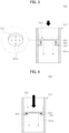
FIGS. 3 and 4 are cross-sectional views illustrating a first embodiment of a metering unit of the hydrogen generation device according to an embodiment of the present disclosure; -
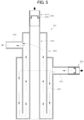
FIG. 5 is a cross-sectional view schematically illustrating the first embodiment of the metering unit, a combustion unit and a reaction unit of the hydrogen generation device according to an embodiment of the present disclosure; -
FIGS. 6 and 7 are cross-sectional views illustrating a second embodiment of the metering unit of the hydrogen generation device according to an embodiment of the present disclosure; -
FIG. 8 is a cross-sectional view schematically illustrating a second embodiment of the metering unit, a combustion unit, and a reaction unit of a hydrogen generation device according to another embodiment of the present disclosure; -
FIG. 9 is a cross-sectional view illustrating a state where uneven flow rate occurs within the metering unit of the hydrogen generation device according to an embodiment of the present disclosure; -
FIGS. 10 and11 are cross-sectional views illustrating a third embodiment of the metering unit of the hydrogen generation device according to an embodiment of the present disclosure; and -
FIG. 12 is a cross-sectional view illustrating a fourth embodiment of the metering unit of the hydrogen generation device according to an embodiment of the present disclosure. - The above and other aspects, features, and advantages of the present disclosure will become apparent from the detailed description of the embodiments to be described in detail below in conjunction with the accompanying drawing. In this regard, it should be understood that the present disclosure is not limited to the following embodiments and may be embodied in various different ways, and that the embodiments are given to provide complete disclosure of the present disclosure and to provide a thorough understanding of the present disclosure to a person who has a common knowledge in the technical field to which the present disclosure belongs. The present disclosure is defined only by the scope of the claims.
- Terms used herein are for the purpose of describing particular embodiments only and are not intended to limit the present disclosure thereto. As used herein, singular forms are intended to include the plural forms as well, unless the context clearly indicates otherwise. It will be further understood that the terms "comprises" and/or "comprising," as used herein, do not preclude the presence or addition of one or more elements other than those mentioned. Like reference numerals refer to like elements throughout the present disclosure, and "and/or" includes each mentioned component and all of one or more combinations of the mentioned components. Although a "first," a "second," etc. are used to describe various components, these components are of course not limited by these terms. These terms are merely used to distinguish one component from another component. Therefore, it goes without saying that the first component mentioned below may also be the second component within the technical spirit of the present disclosure.
- Unless otherwise defined, all terms (including technical and scientific terms) used herein have the same meaning as commonly understood by one of ordinary skill in the art to which the present disclosure pertains. Terms, such as those defined in commonly used dictionaries, are not to be construed in an idealized or overly formal sense unless expressly so defined herein.
- Hereinafter, the present invention will be described in detail with reference to the accompanying drawings.
-
FIG. 1 is a block diagram illustrating the configuration of a hydrogen generation device according to an embodiment of the present disclosure.FIG. 2 is a perspective view illustrating a distribution unit of the hydrogen generation device according to an embodiment of the present disclosure; - As shown in
FIG. 1 , the hydrogen generation device according to an embodiment of the present disclosure may include a plurality ofcylinders 100, a plurality ofcombustion units 200, afuel supply unit 300, adistribution unit 400 and a plurality ofreaction units 500. - The plurality of
cylinders 100 may function as a basic body of the hydrogen generation device. Thecombustion unit 200 and thereaction unit 500 may be disposed in eachcylinder 100. In one embodiment, thecylinder 100 may have a shape surrounding thecombustion unit 200 and thereaction unit 500. - Each of the plurality of
combustion units 200 may be provided in each of the plurality ofcylinders 100 to combust fuel. Eachcombustion unit 200 may receive a uniform quantity of fuel through thefuel supply unit 300 and thedistribution unit 400. In one embodiment, the fuel may include hydrogen and nitrogen. - In one embodiment, a burner may be used as the
combustion unit 200. The burner may ignite the fuel to generate combustion heat. - The
fuel supply unit 300 may serve to supply the fuel to thedistribution unit 400. In one embodiment, thefuel supply unit 300 may deliver the fuel stored in a fuel storage tank (not shown) to thedistribution unit 400 by pumping the fuel with a fuel pump (not shown). - The
distribution unit 400 may deliver the fuel supplied from thefuel supply unit 300 to each of the plurality ofcombustion units 200 by distributing the fuel in a uniform quantity. Accordingly, as a uniform quantity of fuel is burnt by each of the plurality ofcombustion units 200, the temperature distribution for each internal region among the plurality ofcylinders 100, to which the combustion heat from the plurality ofcombustion units 200 is respectively transmitted, may be equalized. Thereby, a reforming reaction of the feed may occur in all of the plurality ofreaction units 500 disposed in each of the plurality ofcylinders 100. For example, if the temperature distributions for each internal region between the plurality ofcylinders 100 are different, the reference temperature of aspecific cylinder 100 is excessively high while the reference temperature of anotherspecific cylinder 100 is excessively low, such that the reforming reaction of feed may not occur in allcylinders 100. The reference temperature may be 800°C to 900°C. - In one embodiment, the feed may include methane and steam for a steam reforming reaction.
- In one embodiment, the feed may include ammonia for an ammonia reforming reaction.
- As shown in
FIG. 2 , thedistribution unit 400 may include aninlet pipe 410, amooring pipe 420, and a plurality ofdistribution pipes 430. - The fuel supplied from the
fuel supply unit 300 may flow into theinlet pipe 410. In one embodiment, theinlet pipe 410 may have a curved pipe shape. - The fuel transferred from the
inlet pipe 410 may flow in themooring pipe 420. Referring toFIG. 2 , themooring pipe 420 may be connected to a lower end of theinlet pipe 410. Accordingly, the fuel flowing into theinlet pipe 410 may be transferred to themooring pipe 420 by a drop, i.e., by a difference in height. - In one embodiment, the
mooring pipe 420 may have a horizontal pipe shape. In another embodiment, themooring pipe 420 may have a vertical pipe shape. - The plurality of
distribution pipes 430 may transfer the fuel flowing in themooring pipe 420 to each of the plurality ofcombustion units 200 by distributing the fuel in a uniform quantity. - In one embodiment, the plurality of
distribution pipes 430 may be connected to the lower side of themooring pipe 420 at a predetermined interval. Accordingly, the fuel flowing in themooring pipe 420 may be distributed to the plurality ofdistribution pipes 430 by a drop. - In one embodiment, the plurality of
distribution pipes 430 may receive a uniform quantity of fuel flowing in themooring pipe 420 through a distribution valve, respectively. A solenoid valve may be used as the distribution valve. - Each of the plurality of
reaction units 500 may be disposed in eachcylinder 100. Hydrogen may be generated by a reforming reaction of the feed supplied from afeed supply unit 700 while thereaction units 500 are heated by the combustion heat transmitted from thecombustion units 200. As shown inFIG. 5 to be further described below, for example, thereaction unit 500 may include afeed supply portion 510 to which the feed is supplied from an outside, areaction portion 520 in which a reforming reaction of the feed occurs to generate hydrogen, and adischarge portion 530 from which the hydrogen generated in thereaction portion 520 is discharged. - In one embodiment, the
feed supply portion 510 may be connected to thereaction portion 520 and may have a shape extending from one side thereof. In one embodiment, thefeed supply portion 510 may have a shape surrounding thereaction portion 520. Additionally, the feed supplied to thefeed supply portion 510 may be preheated by a preheating device. Additionally, thereaction portion 520 may have a shape surrounding thecombustion unit 200. The feed may flow in a zigzag shape inside thefeed supply portion 510 and inside thereaction portion 520, and a reaction flow path connecting thefeed supply portion 510 and thereaction portion 520 may be formed. Additionally, as shown inFIG. 5 to be described below, thedischarge portion 530 may be connected to thereaction portion 520 and may have a shape protruding from the other side of thereaction portion 520. - In one embodiment, the
reaction portion 520 may be provided with a catalyst. For example, nickel, potassium, potassium oxide, calcium, magnesium oxide, and suitable other catalysts accelerating the reaction may be used as the catalyst. In one embodiment, the temperature in thereaction portion 520 may be adjusted to 800°C to 900°C by the combustion heat transmitted from thecombustion unit 200. In one embodiment, thefeed supply unit 700 may deliver the feed stored in a feed storage tank (not shown) to anauxiliary distribution unit 800 to be described below by pumping it with a feed pump (not shown) - Meanwhile, even if the
distribution unit 400 delivers the fuel supplied from thefuel supply unit 300 to each of the plurality ofcombustion units 200 by distributing the fuel in a uniform quantity, an amount of fuel introduced into the plurality ofcombustion units 200 may be different depending on a hydraulic pressure of the fuel delivered to the plurality ofcombustion units 200. Accordingly, the hydrogen generation device may further include ametering unit 600 configured to adjust the amount of fuel delivered to thecombustion unit 200 by thedistribution unit 400 in a fixed quantity. -
FIGS. 3 and 4 are cross-sectional views illustrating a first embodiment of the metering unit of the hydrogen generation device according to an embodiment of the present disclosure.FIG. 5 is a cross-sectional view schematically illustrating the first embodiment of the metering unit, the combustion unit and the reaction unit of the hydrogen generation device according to an embodiment of the present disclosure; - As shown in
FIGS. 3 to 5 , in the first embodiment, themetering unit 600 may be disposed between thedistribution unit 400 and thecombustion unit 200, to adjust the amount of fuel delivered from thedistribution unit 400 to thecombustion unit 200 in a fixed quantity. - A method to produce hydrogen in the hydrogen generation device is comprised of supplying fuel from a
fuel supply unit 300 to thedistribution unit 400, distributing fuel in a uniform quantity to each of the plurality ofcombustion units 200, reacting a feed supplied from afeed supply unit 700 to thereaction units 500 heated by the heat transmitted from thecombustion unit 200 in order to generate hydrogen, and discharging hydrogen generated in thereaction unit 500. Preferably, the fuel is supplied from afuel supply unit 300 to thedistribution unit 400 to deliver fuel in a fixed quantity by themetering unit 600. A stable total amount of hydrogen may be produced by controlling the flow rate in the plurality ofcylinders 100 which respectively accommodate the plurality ofcombustion units 200. The distributing of the fuel for transferring fuel to in a uniform quantity to each of the plurality ofcombustion units 200 may be carried out by changing an opening degree of a connection pipe disposed upstream of each of thecombustion units 200. For changing the opening degree of a respective connection pipe, the metering unit described below may be used. - The
metering unit 600 may include aconnection pipe 610 and anopening adjuster 620. - The
connection pipe 610 may be disposed between thedistribution unit 400 and thecombustion unit 200. In one embodiment, thedistribution unit 400 may be connected to an upper end of theconnection pipe 610, and thecombustion unit 200 may be connected to a lower end of theconnection pipe 610. Accordingly, the fuel transferred from thedistribution unit 400 may be delivered to theconnection pipe 610 and thecombustion unit 200 by a drop. - The
opening adjuster 620 may be disposed in theconnection pipe 610 and may change an opening degree of theconnection pipe 610 depending on a hydraulic pressure of the fuel flowing into theconnection pipe 610. As shown inFIG. 3 , theopening adjuster 620 may include avalve seat 621, avalve disc 622 and aconnector 623. - The
valve seat 621 may extend from an inner peripheral surface of theconnection pipe 610. Thevalve seat 621 may have aseat hole 621a formed therein, through which the fuel passes. In one embodiment, theseat hole 621a may be formed along a central axis of thevalve seat 621. In one embodiment, thevalve seat 621 may have a ring shape. - The
valve disc 622 may be moved in a direction closer to or away from theseat hole 621a depending on the hydraulic pressure of the fuel flowing into theconnection pipe 610 to be delivered, thereby changing the opening degree of theconnection pipe 610. The movement of thevalve disc 622 will be described in detail below. - The
connector 623 may connect thevalve seat 621 and thevalve disc 622. Theconnector 623 may connect thevalve disc 622 to thevalve seat 621 to be moved relative thereto. For example, thevalve disc 622 may move by theconnector 623 while thevalve seat 621 is fixed to the inner peripheral surface of theconnection pipe 610. - In one embodiment, the
connector 623 may include an elastic member for applying an elastic force to thevalve disc 622. The elastic member may generate an elastic force to move thevalve disc 622 in a direction away from thevalve seat 621. - Therefore, if the hydraulic pressure of the fuel delivered to the
valve disc 622 is relatively greater than the elastic force of the elastic member, the elastic member is compressed, and thevalve disc 622 may be moved in a direction closer to theseat hole 621a. Accordingly, as shown inFIG. 4 , the opening degree of theconnection pipe 610 may be reduced. - On the other hand, if the hydraulic pressure of the fuel delivered to the
valve disc 622 is relatively smaller than the elastic force of the elastic member, the elastic member is elastically restored and expanded, and thevalve disc 622 may be moved in a direction away from theseat hole 621a. Accordingly, as shown inFIG. 3 , the opening degree of theconnection pipe 610 may be increased. - Meanwhile, if the opening of the
connection pipe 610 is completely shut off by thevalve disc 622, the flow of fuel in theconnection pipe 610 may be blocked. In this regard, thevalve disc 622 has at least onedisc hole 622a formed therethrough, such that even if the opening of theconnection pipe 610 is completely shut off by thevalve disc 622, it is possible to prevent the flow of fuel in theconnection pipe 610 from being blocked. -
FIGS. 6 and 7 are cross-sectional views illustrating a second embodiment of the metering unit of the hydrogen generation device according to an embodiment of the present disclosure.FIG. 8 is a cross-sectional view schematically illustrating a second embodiment of the metering unit, a combustion unit, and a reaction unit of a hydrogen generation device according to another embodiment of the present disclosure; - As shown in
FIGS. 6 to 8 , in the second embodiment of ametering unit 600, unlike the first embodiment of themetering unit 600, a valve seat 621' may have a shape in which a plurality of tubes having a relatively smaller diameter toward a flow direction of the fuel in theconnection pipe 610 are connected with each other. For example, the valve seat 621' may have a cross section formed in a multistep shape. - In the second embodiment, the diameter of the
valve disc 622 may correspond to the diameter of a tube having the smallest diameter among the plurality of tubes. - Accordingly, in the second embodiment of the
metering unit 600, a moving distance of thevalve disc 622 may be relatively greater than in the first embodiment of themetering unit 600. - The hydrogen generation device according to an embodiment of the present disclosure may further include an
auxiliary distribution unit 800 andauxiliary metering units 900. - The
auxiliary distribution unit 800 may deliver the feed supplied from thefeed supply unit 700 to each of the plurality ofreaction units 500 by distributing the feed in a uniform quantity. For example, theauxiliary distribution unit 800 may deliver the feed supplied from thefeed supply unit 700 to thefeed supply portion 510 of thereaction unit 500. - In one embodiment, the
auxiliary distribution unit 800 may have substantially the same structure as thedistribution unit 400. - The
auxiliary metering units 900 may be disposed in each of thereaction units 500 to adjust an amount of feed supplied to thereaction unit 500 in a fixed quantity. In one embodiment, theauxiliary metering unit 900 may be disposed in thefeed supply portion 510 of thereaction unit 500. - In one embodiment, the
auxiliary metering unit 900 may have substantially the same structure as the first embodiment of themetering unit 600. - In one embodiment, the
auxiliary metering unit 900 may have substantially the same structure as the second embodiment of themetering unit 600. -
FIG. 9 is a cross-sectional view illustrating a state where uneven flow rate occurs within the metering unit of the hydrogen generation device according to an embodiment of the present disclosure.FIGS. 10 and11 are cross-sectional views illustrating a third embodiment of the metering unit of the hydrogen generation device according to an embodiment of the present disclosure. - Referring to
FIG. 9 , an unevenness in a flow rate may occur within themetering unit 600 of the hydrogen generation device according to an embodiment of the present disclosure. As an example, as shown inFIG. 9 , non-uniformity between a first flow rate F1 and a second flow rate F2 may occur in themetering unit 600. - In this case, magnitudes of forces applied to a
first connector 623' and asecond connector 623" which connect thevalve seat 621 and thevalve disc 622 on opposite sides may be different from each other, and compression degrees of the respective connectors may be different from each other. Accordingly, thevalve disc 622 may be tilted, and theopening adjuster 620 may not temporarily adjust the flow rate. - In this regard, the
opening adjuster 620 included in the hydrogen generation device according to an embodiment of the present disclosure may further include anauxiliary valve seat 631 and anauxiliary connector 633. Accordingly, tilting of thevalve disc 622 due to the uneven flow rate may be prevented. - As shown in
FIG. 10 , anauxiliary valve seat 631 may be located upstream from thevalve seat 621 based on flow of the fuel, and may be fixed to an inner wall of theconnection pipe 610. One end of each of the plurality ofauxiliary connectors 633 may be connected to theauxiliary valve seat 631, and the other end thereof may be connected to thevalve disc 622. Theauxiliary connector 633 may be connected to one side of both sides of thevalve disc 622, which is a side opposite to the side to which theconnector 623 is connected. Theauxiliary connector 623 may include an elastic member which generates an elastic force to move thevalve disc 622 in a direction closer to theauxiliary valve seat 631. - In one embodiment, similar to the
valve seat 621, theauxiliary valve seat 631 may extend from the inner peripheral surface of theconnection pipe 610. Theauxiliary valve seat 631 may have a seat hole formed therein, through which the fuel passes. In one embodiment, theauxiliary valve seat 631 may have a ring shape. - Referring to
FIG. 11 , if an unevenness between the first flow rate F1 and the second flow rate F2 occurs in the metering unit, the magnitudes of the forces applied to thefirst connector 623' and thesecond connector 623" may be different from each other, and thefirst connector 623' may be compressed to a greater extent than thesecond connector 623". - A force applied to the first auxiliary connector 633' may be greater than a force applied to the second
auxiliary connector 633". Accordingly, the first auxiliary connector 633' may generate a relatively greater elastic force than the secondauxiliary connector 633". The elastic forces generated by the first auxiliary connector 633' and the secondauxiliary connector 633" may be elastic forces to move thevalve disc 622 in a direction closer to theauxiliary valve seat 631. - The first auxiliary connector 633' may provide an elastic force in a direction opposite to a force applied to the
first connector 623', and the secondauxiliary connector 633" may provide an elastic force in a direction opposite to a force applied to thesecond connector 623". The first auxiliary connector 633' generates a relatively greater elastic force than the secondauxiliary connector 633 ", and thus the imbalance in the forces applied to thefirst connector 623' and thesecond connector 623" may be alleviated. Accordingly, despite the unevenness in the flow rate within themetering unit 600, a tilting degree of thevalve disc 622 may be greatly reduced. - In one embodiment, an elastic modulus of the elastic member included in the
auxiliary connector 633 may be smaller than an elastic modulus of the elastic member included in theconnector 623. Accordingly, theauxiliary connector 633 may be used to prevent thevalve disc 622 from being tilted. -
FIG. 12 is a cross-sectional view illustrating a fourth embodiment of the metering unit of the hydrogen generation device according to an embodiment of the present disclosure. - Referring to
FIG. 12 , theopening adjuster 620 included in the hydrogen generation device according to an embodiment of the present disclosure may further include aguide ring 641 and a plurality ofguide ring connectors 642. - The
guide ring 641 is disposed in close contact with the inner wall of theconnection pipe 610 to be moved along the inner wall of theconnection pipe 610 in an up and down direction, i.e., a vertical direction. The vertical direction refers to a direction parallel to a direction in which theconnection pipe 610 extends, and an upstream direction in terms of the fuel flow is upward, and a downstream direction is downward. - In one embodiment, the
guide ring 641 may have a ring shape. - The
guide ring connectors 642 may connect theguide ring 641 and thevalve disc 622. Accordingly, a vertical movement of theguide ring 641 may occur together with a vertical movement of thevalve disc 622. - The
guide ring 641 may be formed to have a minimum thickness so as not to interfere the flow of fuel. Theguide ring 641 may prevent thevalve disc 622 from tilting within themetering unit 600, which may be caused by the uneven flow rate occurring within themetering unit 600. For example, theguide ring 641 moves in the vertical direction in close contact with the inner wall of theconnection pipe 610, so that tilting thereof may be prevented even when forces of different magnitudes are applied to each region of theguide ring 641. Accordingly, even if an unevenness in the flow rate occurs within themetering unit 600, theguide ring 641 may only move in the vertical direction without being tilted. Therefore, even if the unevenness in the flow rate occurs within themetering unit 600, thevalve disc 622 may only move in the vertical direction by theguide ring 641. - The
guide ring 641 and theguide ring connectors 642 may be utilized together with theauxiliary valve seat 631 andauxiliary connector 633 shown inFIG. 10 . - In the hydrogen generation device according to an embodiment of the present disclosure, a uniform quantity of fuel may be supplied to the plurality of
combustion units 200 provided in each of the plurality ofcylinders 100 having a size capable of equalizing the temperature distribution for each internal region. Thereby, the temperature distribution for each internal region of the plurality ofcylinders 100 may be equalized, and the hydrogen production volume may be increased. - In the hydrogen generation device according to an embodiment of the present disclosure, even if an unevenness in the flow rate occurs inside one cylinder, hydrogen may be stably produced by stably controlling the flow rate of the corresponding cylinder.
- As such, embodiments of the present disclosure have been described with reference to the accompanying drawings, but it should be understood by those skilled in the art that the present disclosure may be implemented in other specific embodiments without changing the technical idea and essential characteristics of the disclosure. Accordingly, it should be understood that the above-described embodiments are only intended to illustrate the present disclosure and are not intended to limit the scope thereof in all aspects.
Claims (15)
- A hydrogen generation device comprising:a plurality of cylinders (100);a plurality of combustion units (200) disposed in the plurality of cylinders (100), respectively, to combust a fuel;a distribution unit (400) configured to deliver the fuel supplied from a fuel supply unit (300) to each of the plurality of combustion units (200) by distributing the fuel in a uniform quantity;a plurality of reaction units (500) disposed in the plurality of cylinders (100), respectively, to generate hydrogen by a reforming reaction of a feed supplied from a feed supply unit (700) while the reaction units (500) are heated by a combustion heat transmitted from the combustion unit (200); anda metering unit (600) disposed between the distribution unit (400) and the combustion unit (200) respectively in each of the cylinders (100) to adjust an amount of the fuel delivered from the distribution unit (400) to the combustion unit (200) in a fixed quantity,wherein the respective metering unit (600) comprises:a connection pipe (610) disposed between the distribution unit (400) and the combustion unit (200); andan opening adjuster (620) disposed in the connection pipe (610) to change an opening degree of the connection pipe (610) depending on a hydraulic pressure of the fuel.
- The hydrogen generation device according to claim 1, wherein the opening adjuster (620) comprises:a valve seat (621) extending from an inner peripheral surface of the connection pipe (610) and having a seat hole (621a) formed therein through which the fuel passes;a valve disc (622) which moves relative to the seat hole (621a) depending on the hydraulic pressure of the fuel to change the opening degree of the connection pipe (610); anda connector (623, 633, 642) which connects the valve disc (622) to the valve seat (621) to be moved relative thereto.
- The hydrogen generation device according to claim 2, wherein the connector (623, 633, 642) comprises an elastic member configured to move the valve disc (622) in a direction away from the valve seat (621).
- The hydrogen generation device according to claim 2 or 3, wherein the valve disc (622) has at least one disc hole formed therein.
- The hydrogen generation device according to any one of claims 2 to 4, wherein the valve seat (621) has a shape in which a plurality of tubes having a relatively smaller diameter toward a flow direction of the fuel are connected with each other.
- The hydrogen generation device according to any one of claims 2 to 5, wherein the opening adjuster (620) further comprises:an auxiliary valve seat (631) located upstream from the valve seat (621) based on flow of the fuel, and extending from the inner peripheral surface of the connection pipe (610) to form a seat hole (621a) through which the fuel passes; andan auxiliary connector (623, 633) which connects the auxiliary valve seat (631) and the valve disc (622).
- The hydrogen generation device according to claim 6, wherein the connector (623, 633, 642) comprises an elastic member configured to generate an elastic force to move the valve disc (622) in a direction away from the valve seat (621), and
the auxiliary connector (623, 633) comprises an elastic member configured to generate an elastic force to move the valve disc (622) in a direction closer to the auxiliary valve seat (631). - The hydrogen generation device according to claim 7, wherein an elastic modulus of the elastic member included in the auxiliary connector (623, 633) is smaller than an elastic modulus of the elastic member included in the connector (623, 633, 642).
- The hydrogen generation device according to any one of claims 2 to 8, wherein the opening adjuster (620) further comprises:a guide ring (641) disposed in contact with an inner wall of the connection pipe (610) to be moved along the inner wall of the connection pipe (610); anda guide ring connector (642) which connects the guide ring (641) and the valve disc (622).
- The hydrogen generation device according to any one of the preceding claims, further comprising:an auxiliary distribution unit (800), which further to the distribution unit (400) is configured to deliver the feed supplied from the feed supply unit (700) to each of the plurality of reaction units (500) by distributing the feed in a uniform quantity; andan auxiliary metering unit (900), which further to the metering unit (600) is disposed in the reaction units (500) to adjust an amount of the feed supplied to the reaction unit (500) in a fixed quantity,optionally wherein a further opening adjuster is comprised in the auxiliary metering unit (900) to adjust the amount of the feed.
- A method to produce hydrogen in a hydrogen generation device which comprises a plurality of combustion units (200) to combust a fuel and a plurality of reaction units (500), the method comprising:supplying the fuel and distributing the fuel in a uniform quantity to each of the plurality of combustion units (200);reacting the supplied fuel in each of the reaction units (500) heated by the heat transmitted from the combustion unit (200) in order to generate hydrogen; anddischarging hydrogen generated in each of the reaction unit (500);wherein supplying the fuel is adjusted to deliver fuel in a fixed quantity to each of the combustion units (200).
- The method of claim 11, wherein the fuel is supplied and distributed to each of the plurality of combustion units (200) in a uniform quantity to equalize the temperature distribution for each internal region of a plurality of cylinders (100) which respectively accommodate the plurality of combustion units (200),
wherein the supplying and the distributing of the fuel sets the temperature in each of the combustion unit to be, during the production phase, in a range of 800 to 900°C. - The method of claim 11 or 12, wherein a stable total amount of hydrogen is produced by controlling the flow rate in a plurality of cylinders (100) which respectively accommodate the plurality of combustion units (200).
- The method of any one of claims 11 to 13,
wherein the distributing of the fuel for transferring fuel to in a uniform quantity to each of the plurality of combustion units (200) is carried out by changing an opening degree of a connection pipe (610) disposed upstream of each of the combustion units (200), respectively. - The method of any one of claims 11 to 14, wherein hydrogen is produced using a hydrogen steam reforming reaction or an ammonia reforming reaction.
Applications Claiming Priority (2)
| Application Number | Priority Date | Filing Date | Title |
|---|---|---|---|
| KR20230042745 | 2023-03-31 | ||
| KR1020230095367A KR102757705B1 (en) | 2023-03-31 | 2023-07-21 | Hydrogen gereration device |
Publications (1)
| Publication Number | Publication Date |
|---|---|
| EP4445998A1 true EP4445998A1 (en) | 2024-10-16 |
Family
ID=90468869
Family Applications (1)
| Application Number | Title | Priority Date | Filing Date |
|---|---|---|---|
| EP24165733.7A Pending EP4445998A1 (en) | 2023-03-31 | 2024-03-25 | Hydrogen generation device and method to produce hydrogen |
Country Status (4)
| Country | Link |
|---|---|
| US (1) | US20240326005A1 (en) |
| EP (1) | EP4445998A1 (en) |
| JP (2) | JP2024146801A (en) |
| AU (1) | AU2024201707B2 (en) |
Citations (4)
| Publication number | Priority date | Publication date | Assignee | Title |
|---|---|---|---|---|
| US20030131533A1 (en) * | 2002-01-14 | 2003-07-17 | Hoanh Nang Pham | Apparatus and method for production of synthesis gas using radiant and convective reforming |
| US20080090112A1 (en) * | 2006-10-13 | 2008-04-17 | Samsung Sdi Co., Ltd. | Hydrogen generator and method of operating the same |
| US20100193741A1 (en) * | 2007-04-25 | 2010-08-05 | Uhde Gmbh | Primary reformer with secondary inlet channels supplying the burner |
| WO2017134225A1 (en) * | 2016-02-04 | 2017-08-10 | Technip France | Method for reducing temperature spread in reformer |
Family Cites Families (9)
| Publication number | Priority date | Publication date | Assignee | Title |
|---|---|---|---|---|
| JPS57178949U (en) * | 1981-05-09 | 1982-11-12 | ||
| US6920895B2 (en) * | 2001-04-16 | 2005-07-26 | Alan Avis | Combination surge supression and safety shut-off valve |
| KR101292737B1 (en) * | 2007-11-02 | 2013-08-05 | 에스케이이노베이션 주식회사 | Hydrogen generating apparatus using steam reforming reaction |
| JP2010031922A (en) * | 2008-07-26 | 2010-02-12 | Fuji Seiko Kk | Throttle device |
| EP2492534A1 (en) * | 2011-02-25 | 2012-08-29 | Öhlins Racing Ab | Valve device |
| JP6665004B2 (en) * | 2016-03-22 | 2020-03-13 | 三菱重工業株式会社 | Fuel supply device, marine boiler provided with the same, and method of controlling fuel supply device |
| DE102016006887B4 (en) * | 2016-06-03 | 2025-05-28 | Fresenius Medical Care Deutschland Gmbh | Constant flow restrictor and dialysis machine |
| CN109826969A (en) * | 2019-04-03 | 2019-05-31 | 郭怀宝 | The adjustable valve of the amount of restriction of a kind of pair of fluid |
| JP2022112537A (en) * | 2021-01-22 | 2022-08-03 | パナソニックIpマネジメント株式会社 | Hydrogen generation system, hydrogen production system or fuel cell system using the same, and operation method thereof |
-
2024
- 2024-03-13 JP JP2024039286A patent/JP2024146801A/en active Pending
- 2024-03-13 US US18/603,207 patent/US20240326005A1/en active Pending
- 2024-03-15 AU AU2024201707A patent/AU2024201707B2/en active Active
- 2024-03-25 EP EP24165733.7A patent/EP4445998A1/en active Pending
-
2025
- 2025-12-03 JP JP2025225873A patent/JP2026031672A/en active Pending
Patent Citations (4)
| Publication number | Priority date | Publication date | Assignee | Title |
|---|---|---|---|---|
| US20030131533A1 (en) * | 2002-01-14 | 2003-07-17 | Hoanh Nang Pham | Apparatus and method for production of synthesis gas using radiant and convective reforming |
| US20080090112A1 (en) * | 2006-10-13 | 2008-04-17 | Samsung Sdi Co., Ltd. | Hydrogen generator and method of operating the same |
| US20100193741A1 (en) * | 2007-04-25 | 2010-08-05 | Uhde Gmbh | Primary reformer with secondary inlet channels supplying the burner |
| WO2017134225A1 (en) * | 2016-02-04 | 2017-08-10 | Technip France | Method for reducing temperature spread in reformer |
Also Published As
| Publication number | Publication date |
|---|---|
| US20240326005A1 (en) | 2024-10-03 |
| AU2024201707B2 (en) | 2025-09-04 |
| JP2026031672A (en) | 2026-02-24 |
| AU2024201707A1 (en) | 2024-10-17 |
| JP2024146801A (en) | 2024-10-15 |
Similar Documents
| Publication | Publication Date | Title |
|---|---|---|
| CN110890572B (en) | Solid oxide fuel cell power generation system based on oil fuel | |
| CN101499534B (en) | A solid oxide fuel cell distributed heat and power cogeneration system | |
| EP2232622B1 (en) | Steam methane reformer and hydrogen station having it using high performing metal fiber burner | |
| US10381665B2 (en) | Device and method for heating fuel cell stack and fuel cell system having the device | |
| JPH05266911A (en) | Solid oxide fuel cell powder generating device | |
| US20090042071A1 (en) | Multi-tube fuel reformer with augmented heat transfer | |
| US9246181B2 (en) | Fuel cell module | |
| JP6355211B2 (en) | Evaporating apparatus and fuel cell system using the same | |
| WO2009057909A2 (en) | Hydrogen generating apparatus using steam reforming reaction | |
| CN115411297A (en) | A fuel cell power generation system | |
| US20240326005A1 (en) | Hydrogen generation device | |
| CN115458765B (en) | A metal hollow supported solid oxide fuel cell stack and power generation module | |
| KR101429652B1 (en) | High temperature type fuel cell system with use of temperature improved | |
| KR100572061B1 (en) | Reformer for Fuel Cell | |
| KR102757705B1 (en) | Hydrogen gereration device | |
| KR101490691B1 (en) | a BOP system of solid oxide fuel cell, a stack module of solid oxide fuel cell including it and an operating method to increase thermal efficiency thereof | |
| KR20200116275A (en) | Expandible Multi-Channel Cylindrical steam reforming reactor | |
| CN118718883A (en) | Hydrogen generator | |
| KR102662302B1 (en) | System of power generation through gas expansion | |
| CN221841876U (en) | Internal reforming solid oxide fuel cell power generation system | |
| KR102390611B1 (en) | Hybrid system for reforming fuel and method for reforming fuel using the same | |
| JP2001015134A (en) | Combined power generation system of fuel cell and gas turbine | |
| CN110931823A (en) | Reforming device, methanol water reforming hydrogen production equipment and method, and power generation equipment and method | |
| CN119500046B (en) | Cladding type methanol reforming hydrogen production reactor and system utilizing waste heat of combustion tail gas | |
| CN121854830A (en) | Large-scale pure ammonia power station boiler system and operation method thereof |
Legal Events
| Date | Code | Title | Description |
|---|---|---|---|
| PUAI | Public reference made under article 153(3) epc to a published international application that has entered the european phase |
Free format text: ORIGINAL CODE: 0009012 |
|
| STAA | Information on the status of an ep patent application or granted ep patent |
Free format text: STATUS: REQUEST FOR EXAMINATION WAS MADE |
|
| 17P | Request for examination filed |
Effective date: 20240325 |
|
| AK | Designated contracting states |
Kind code of ref document: A1 Designated state(s): AL AT BE BG CH CY CZ DE DK EE ES FI FR GB GR HR HU IE IS IT LI LT LU LV MC ME MK MT NL NO PL PT RO RS SE SI SK SM TR |
|
| STAA | Information on the status of an ep patent application or granted ep patent |
Free format text: STATUS: EXAMINATION IS IN PROGRESS |
|
| 17Q | First examination report despatched |
Effective date: 20250526 |