EP4445848A1 - Devices and systems for transvaginal, ultrasound guided hysteroscopic surgical procedures - Google Patents
Devices and systems for transvaginal, ultrasound guided hysteroscopic surgical procedures Download PDFInfo
- Publication number
- EP4445848A1 EP4445848A1 EP24169978.4A EP24169978A EP4445848A1 EP 4445848 A1 EP4445848 A1 EP 4445848A1 EP 24169978 A EP24169978 A EP 24169978A EP 4445848 A1 EP4445848 A1 EP 4445848A1
- Authority
- EP
- European Patent Office
- Prior art keywords
- collar
- shaft
- relative
- hysteroscope
- ultrasound
- Prior art date
- Legal status (The legal status is an assumption and is not a legal conclusion. Google has not performed a legal analysis and makes no representation as to the accuracy of the status listed.)
- Pending
Links
Images







Classifications
-
- A—HUMAN NECESSITIES
- A61—MEDICAL OR VETERINARY SCIENCE; HYGIENE
- A61B—DIAGNOSIS; SURGERY; IDENTIFICATION
- A61B8/00—Diagnosis using ultrasonic, sonic or infrasonic waves
- A61B8/44—Constructional features of the ultrasonic, sonic or infrasonic diagnostic device
- A61B8/4444—Constructional features of the ultrasonic, sonic or infrasonic diagnostic device related to the probe
- A61B8/445—Details of catheter construction
-
- A—HUMAN NECESSITIES
- A61—MEDICAL OR VETERINARY SCIENCE; HYGIENE
- A61B—DIAGNOSIS; SURGERY; IDENTIFICATION
- A61B8/00—Diagnosis using ultrasonic, sonic or infrasonic waves
- A61B8/12—Diagnosis using ultrasonic, sonic or infrasonic waves in body cavities or body tracts, e.g. by using catheters
-
- A—HUMAN NECESSITIES
- A61—MEDICAL OR VETERINARY SCIENCE; HYGIENE
- A61B—DIAGNOSIS; SURGERY; IDENTIFICATION
- A61B1/00—Instruments for performing medical examinations of the interior of cavities or tubes of the body by visual or photographical inspection, e.g. endoscopes; Illuminating arrangements therefor
- A61B1/00131—Accessories for endoscopes
- A61B1/0014—Fastening element for attaching accessories to the outside of an endoscope, e.g. clips, clamps or bands
-
- A—HUMAN NECESSITIES
- A61—MEDICAL OR VETERINARY SCIENCE; HYGIENE
- A61B—DIAGNOSIS; SURGERY; IDENTIFICATION
- A61B1/00—Instruments for performing medical examinations of the interior of cavities or tubes of the body by visual or photographical inspection, e.g. endoscopes; Illuminating arrangements therefor
- A61B1/012—Instruments for performing medical examinations of the interior of cavities or tubes of the body by visual or photographical inspection, e.g. endoscopes; Illuminating arrangements therefor characterised by internal passages or accessories therefor
- A61B1/018—Instruments for performing medical examinations of the interior of cavities or tubes of the body by visual or photographical inspection, e.g. endoscopes; Illuminating arrangements therefor characterised by internal passages or accessories therefor for receiving instruments
-
- A—HUMAN NECESSITIES
- A61—MEDICAL OR VETERINARY SCIENCE; HYGIENE
- A61B—DIAGNOSIS; SURGERY; IDENTIFICATION
- A61B1/00—Instruments for performing medical examinations of the interior of cavities or tubes of the body by visual or photographical inspection, e.g. endoscopes; Illuminating arrangements therefor
- A61B1/303—Instruments for performing medical examinations of the interior of cavities or tubes of the body by visual or photographical inspection, e.g. endoscopes; Illuminating arrangements therefor for the vagina, i.e. vaginoscopes
-
- A—HUMAN NECESSITIES
- A61—MEDICAL OR VETERINARY SCIENCE; HYGIENE
- A61B—DIAGNOSIS; SURGERY; IDENTIFICATION
- A61B8/00—Diagnosis using ultrasonic, sonic or infrasonic waves
- A61B8/42—Details of probe positioning or probe attachment to the patient
-
- A—HUMAN NECESSITIES
- A61—MEDICAL OR VETERINARY SCIENCE; HYGIENE
- A61B—DIAGNOSIS; SURGERY; IDENTIFICATION
- A61B8/00—Diagnosis using ultrasonic, sonic or infrasonic waves
- A61B8/42—Details of probe positioning or probe attachment to the patient
- A61B8/4209—Details of probe positioning or probe attachment to the patient by using holders, e.g. positioning frames
-
- A—HUMAN NECESSITIES
- A61—MEDICAL OR VETERINARY SCIENCE; HYGIENE
- A61B—DIAGNOSIS; SURGERY; IDENTIFICATION
- A61B8/00—Diagnosis using ultrasonic, sonic or infrasonic waves
- A61B8/44—Constructional features of the ultrasonic, sonic or infrasonic diagnostic device
- A61B8/4444—Constructional features of the ultrasonic, sonic or infrasonic diagnostic device related to the probe
- A61B8/4461—Features of the scanning mechanism, e.g. for moving the transducer within the housing of the probe
- A61B8/4466—Features of the scanning mechanism, e.g. for moving the transducer within the housing of the probe involving deflection of the probe
-
- A—HUMAN NECESSITIES
- A61—MEDICAL OR VETERINARY SCIENCE; HYGIENE
- A61B—DIAGNOSIS; SURGERY; IDENTIFICATION
- A61B8/00—Diagnosis using ultrasonic, sonic or infrasonic waves
- A61B8/44—Constructional features of the ultrasonic, sonic or infrasonic diagnostic device
- A61B8/4483—Constructional features of the ultrasonic, sonic or infrasonic diagnostic device characterised by features of the ultrasound transducer
- A61B8/4494—Constructional features of the ultrasonic, sonic or infrasonic diagnostic device characterised by features of the ultrasound transducer characterised by the arrangement of the transducer elements
-
- A—HUMAN NECESSITIES
- A61—MEDICAL OR VETERINARY SCIENCE; HYGIENE
- A61B—DIAGNOSIS; SURGERY; IDENTIFICATION
- A61B1/00—Instruments for performing medical examinations of the interior of cavities or tubes of the body by visual or photographical inspection, e.g. endoscopes; Illuminating arrangements therefor
- A61B1/00064—Constructional details of the endoscope body
- A61B1/00066—Proximal part of endoscope body, e.g. handles
-
- A—HUMAN NECESSITIES
- A61—MEDICAL OR VETERINARY SCIENCE; HYGIENE
- A61B—DIAGNOSIS; SURGERY; IDENTIFICATION
- A61B1/00—Instruments for performing medical examinations of the interior of cavities or tubes of the body by visual or photographical inspection, e.g. endoscopes; Illuminating arrangements therefor
- A61B1/012—Instruments for performing medical examinations of the interior of cavities or tubes of the body by visual or photographical inspection, e.g. endoscopes; Illuminating arrangements therefor characterised by internal passages or accessories therefor
- A61B1/015—Control of fluid supply or evacuation
-
- A—HUMAN NECESSITIES
- A61—MEDICAL OR VETERINARY SCIENCE; HYGIENE
- A61B—DIAGNOSIS; SURGERY; IDENTIFICATION
- A61B1/00—Instruments for performing medical examinations of the interior of cavities or tubes of the body by visual or photographical inspection, e.g. endoscopes; Illuminating arrangements therefor
- A61B1/06—Instruments for performing medical examinations of the interior of cavities or tubes of the body by visual or photographical inspection, e.g. endoscopes; Illuminating arrangements therefor with illuminating arrangements
- A61B1/07—Instruments for performing medical examinations of the interior of cavities or tubes of the body by visual or photographical inspection, e.g. endoscopes; Illuminating arrangements therefor with illuminating arrangements using light-conductive means, e.g. optical fibres
-
- A—HUMAN NECESSITIES
- A61—MEDICAL OR VETERINARY SCIENCE; HYGIENE
- A61B—DIAGNOSIS; SURGERY; IDENTIFICATION
- A61B17/00—Surgical instruments, devices or methods
- A61B17/32—Surgical cutting instruments
- A61B17/320016—Endoscopic cutting instruments, e.g. arthroscopes, resectoscopes
- A61B17/32002—Endoscopic cutting instruments, e.g. arthroscopes, resectoscopes with continuously rotating, oscillating or reciprocating cutting instruments
-
- A—HUMAN NECESSITIES
- A61—MEDICAL OR VETERINARY SCIENCE; HYGIENE
- A61B—DIAGNOSIS; SURGERY; IDENTIFICATION
- A61B17/00—Surgical instruments, devices or methods
- A61B17/42—Gynaecological or obstetrical instruments or methods
- A61B2017/4216—Operations on uterus, e.g. endometrium
-
- A—HUMAN NECESSITIES
- A61—MEDICAL OR VETERINARY SCIENCE; HYGIENE
- A61B—DIAGNOSIS; SURGERY; IDENTIFICATION
- A61B90/00—Instruments, implements or accessories specially adapted for surgery or diagnosis and not covered by any of the groups A61B1/00 - A61B50/00, e.g. for luxation treatment or for protecting wound edges
- A61B90/03—Automatic limiting or abutting means, e.g. for safety
- A61B2090/033—Abutting means, stops, e.g. abutting on tissue or skin
- A61B2090/034—Abutting means, stops, e.g. abutting on tissue or skin abutting on parts of the device itself
-
- A—HUMAN NECESSITIES
- A61—MEDICAL OR VETERINARY SCIENCE; HYGIENE
- A61B—DIAGNOSIS; SURGERY; IDENTIFICATION
- A61B90/00—Instruments, implements or accessories specially adapted for surgery or diagnosis and not covered by any of the groups A61B1/00 - A61B50/00, e.g. for luxation treatment or for protecting wound edges
- A61B90/30—Devices for illuminating a surgical field, the devices having an interrelation with other surgical devices or with a surgical procedure
- A61B2090/306—Devices for illuminating a surgical field, the devices having an interrelation with other surgical devices or with a surgical procedure using optical fibres
-
- A—HUMAN NECESSITIES
- A61—MEDICAL OR VETERINARY SCIENCE; HYGIENE
- A61B—DIAGNOSIS; SURGERY; IDENTIFICATION
- A61B90/00—Instruments, implements or accessories specially adapted for surgery or diagnosis and not covered by any of the groups A61B1/00 - A61B50/00, e.g. for luxation treatment or for protecting wound edges
- A61B90/36—Image-producing devices or illumination devices not otherwise provided for
- A61B90/37—Surgical systems with images on a monitor during operation
- A61B2090/378—Surgical systems with images on a monitor during operation using ultrasound
Definitions
- the present disclosure relates to hysteroscopy and, more particularly, to devices, systems, and methods for transvaginal, ultrasound guided hysteroscopic surgical procedures.
- Transvaginal hysteroscopy includes both intrauterine procedures, e.g., procedures performed within the uterine cavity, and intramural procedures, e.g., procedures performed within the uterine wall.
- Intrauterine procedures may require different approaches and/or instruments as compared to intramural procedures, and vice versa.
- hysteroscopic procedures may require different approaches and/or instruments depending upon, for example, the procedure to be performed, patient anatomy, technique utilized, and/or other considerations.
- distal refers to the portion that is being described which is farther from a user
- proximal refers to the portion that is being described which is closer to a user
- a transvaginal ultrasound device including a collar, a body, and an ultrasound sensor assembly.
- the collar defines a longitudinal lumen configured to receive a shaft for slidably positioning the collar about the shaft.
- the body depends from the collar and protrudes distally relative to the collar.
- the ultrasound sensor assembly is disposed within the body and configured for ultrasound imaging.
- the collar and the body are configured for full insertion through a vaginal introitus and into a vaginal canal of a human patient for positioning the longitudinal lumen of the collar in substantial alignment with a cervix of the human patient to enable the shaft to extend through the cervix and into a uterus of the human patient.
- the device further includes a locking mechanism configured to releasably lock the collar about the shaft to at least one of slidably or rotationally fix the collar relative to the shaft.
- the locking mechanism may include a locking drive assembly configured to transition the locking mechanism between a locked condition and an unlocked condition.
- the body is fixed relative to the collar.
- the body is movable relative to the collar. More specifically, the body may be rotatable, slidable, and/or pivotable relative to the collar.
- the device further includes a drive assembly configured to move the body relative to the collar.
- a hysteroscopic surgical system includes a hysteroscope including a handle and a shaft extending distally from the handle, and an ultrasound device.
- the ultrasound device includes a collar defining a longitudinal lumen configured to receive the shaft for slidably positioning the collar about the shaft, a body depending from the collar and protruding distally relative to the collar, and an ultrasound sensor assembly disposed within the body.
- the ultrasound sensor assembly is configured for ultrasound imaging.
- the collar and the body are configured for positioning within a vaginal canal of a human patient for positioning the longitudinal lumen of the collar in substantial alignment with a cervix of the human patient to enable the shaft to extend through the cervix and into a uterus of the human patient.
- the shaft of the hysteroscope includes a first portion defining a first diameter and a second portion defining a second diameter greater than the first diameter.
- the longitudinal lumen of the collar may define a third diameter greater than the first diameter but less than the second diameter to enable slidable positioning the collar about the first portion of the shaft and inhibit sliding of the collar onto the second portion of the shaft.
- the hysteroscopic surgical system further includes a spacer configured for positioning about the shaft of the hysteroscope proximally of the collar.
- the spacer is configured to define an extent of distal insertion of the shaft of the hysteroscope through the collar.
- the spacer is configured for positioning about the shaft of the hysteroscope between the collar and a transition defined along the shaft.
- the hysteroscopic surgical system further includes a locking mechanism configured to releasably lock the collar about the shaft to at least one of slidably or rotationally fix the collar relative to the shaft.
- the locking mechanism may include a locking drive assembly configured to transition the locking mechanism between a locked condition and an unlocked condition.
- the body is fixed relative to the collar.
- the body is movable relative to the collar.
- the body may be rotatable, slidable, and/or pivotable relative to the collar.
- a hysteroscopic system provided in accordance with the present disclosure is shown generally identified by reference numeral 10 including a working device 100, e.g., a tissue resection device, an ablation device, a biopsy device, etc.; a hysteroscope 200; and an ultrasound device 300.
- Ultrasound device 300 is configured for transvaginal insertion into position adjacent to or in abutment with tissue surrounding the cervix of a patient (e.g., a human patient).
- Hysteroscope 200 is configured for insertion through ultrasound device 300 and the cervix into the uterus of the patient.
- Working device 100 is configured for insertion through hysteroscope 200 and into the uterus of the patient to perform a surgical procedure in the uterine cavity and/or within the uterine wall.
- a hysteroscopic system for performing a surgical procedure within the uterus e.g., within the uterine cavity and/or within the uterine wall
- the aspects and features of the present disclosure are also applicable for use in other endoscopic procedures such as ultrasound guided endoscopic surgical procedures.
- Working device 100 may be a tissue resection device, an ablation device, a biopsy device, or other suitable working device configured for use on or within the uterus.
- working device 100 includes a housing 110, a shaft 120, a cutting member 130, a drive mechanism 140, an outflow port 150, and a cable 160.
- Housing 110 houses drive mechanism 140 therein and functions as a handle to enable a user to grasp working device 100.
- Drive mechanism 140 includes a motor and is operably coupled to cutting member 130 to drive rotation and/or translation of cutting member 130 relative to shaft 120.
- Drive mechanism 140 is adapted to connect to a control unit (not shown) via cable 160 for powering and controlling the motor, although working device 100 may alternatively be battery powered or manually powered.
- a suction source (not shown) incorporated into the control unit (not shown), or any other suitable vacuum creating mechanism, may also be provided to facilitate withdrawal of fluid, tissue, and debris through working device 100 and outflow port 150.
- Shaft 120 of working device 100 extends distally from housing 110 and, in aspects, is stationary relative to housing 110, although other configurations are also contemplated.
- Cutting member 130 extends through shaft 120 and is rotatable and/or translatable relative to shaft 120. More specifically, cutting member 130 is operably coupled to drive mechanism 140 for driving the rotation and/or translation of cutting member 130 relative to shaft 120 for cutting and removing tissue. A distal portion of cutting member 130 is exposed via an open distal end of shaft 120 (as shown) and/or a window defined through shaft 120.
- tissue is drawn into shaft 120 and/or cutting member 130.
- tissue is resected via the rotation and/or translation of cutting member 130 relative to shaft 120, thus enabling the resected tissue to be drawn proximally through shaft 120 and/or cutting member 130, along with fluid and debris.
- the resected tissue, fluid, and debris are drawn proximally through outflow port 150 and outflow tubing (not shown) and, ultimately, to one or more collection canisters of a fluid management system (not shown).
- hysteroscope 200 includes a handle 220, a shaft 240, and a removable outflow and/or instrument working channel 260.
- Handle 220 of hysteroscope 200 includes a housing 222, a light post 224, inflow and outflow ports 226, 228, respectively, inflow and outflow valves 227, 229, respectively, and an arm 230.
- Housing 222 defines a generally cylindrical-shaped configuration extending along a longitudinal axis defined by hysteroscope 200.
- Light post 224 extends from housing 222 and is configured to connect to a light source, e.g., to illuminate a distal end of shaft 240 via a plurality of fiber optic strands 232 ( FIG.
- Inflow and outflow ports 226, 228 enable connection of a fluid supply and a fluid collection container, respectively, to hysteroscope 200 to enable the inflow and outflow of fluid through shaft 240 to/from the internal surgical site, e.g., the uterus.
- Inflow and outflow valves 227, 229 enable the selective control of the fluid resistance through inflow and outflow ports 226, 228, respectively, thereby enabling control of fluid flow rate into and out of the internal surgical site.
- Arm 230 is configured to connect to an imaging device, e.g., a camera, to capture images received via optics 234 ( FIG. 2A ) extending through shaft 240 to the distal end of shaft 240 and, thus, enable display of a video image of the internal surgical site as captured by optics 234.
- Shaft 240 of hysteroscope 200 extends distally from handle 220 along the longitudinal axis of hysteroscope 200 and includes including a proximal portion 242 having a first diameter, a distal portion 244 having a second, smaller diameter, and a first transition portion 246a disposed between proximal and distal portions 242, 244, respectively, and tapering from the first diameter to the second diameter to provide a transition between proximal and distal portions 242, 244, respectively.
- a second transition portion 246b may be disposed between proximal portion 242 of shaft 240 and housing 222 of handle 220 to provide a transition tapering from the first diameter of proximal portion 242 of shaft 240 to a third diameter of housing 222 of handle 220 that is greater than the first diameter.
- Distal portion 244 of shaft 240 of hysteroscope 200 is configured for insertion transvaginally through the cervix and into the uterus.
- the relatively small diameter of distal portion 244 of shaft 240 reduces pain and discomfort for the patient and also provides increased flexibility compared to the relatively large diameter proximal portion 244, thus facilitating insertion through the cervix and into the uterus.
- Proximal portion 242 of shaft 240 of hysteroscope 200 defining a relatively large diameter, is configured for insertion transvaginally through the vaginal introitus and into the vaginal canal, but not through the cervix.
- the relatively large diameter proximal portion 242 provides increased structural support to shaft 240 of hysteroscope 200.
- Housing 222 of handle 220 of hysteroscope 220, defining the largest diameter, is configured to remain externally of the patient, to facilitate operating, manipulating, and/or supporting hysteroscope 200.
- Transition portion 246a of shaft 240 of hysteroscope 200 facilitates atraumatic insertion of relatively large diameter proximal portion 242 of shaft 240 of hysteroscope 200 through the vaginal introitus and into the vaginal canal and atraumatic contact with the cervix.
- transition portion 246b of shaft 240 of hysteroscope 200 facilitates atraumatic contact with the vaginal introitus.
- Shaft 240 includes, as noted above, the plurality of fiber optic strands 232 and optics 234 extending therethrough. Shaft 240 further includes a generally D-shaped inflow channel 248 extending therethrough. Inflow channel 248 fluidly communicates with inflow port 226. The plurality of fiber optic strands 232 and optics 234 extend through shaft 240 externally of inflow channel 248.
- Working channel 260 extends through inflow channel 248 and is removable therefrom, although in aspects, working channel 260 is integral with shaft 240.
- Working channel 260 functions as an outflow and/or instrument channel that fluidly communicates with outflow port 228.
- channels 248, 260 may be reversed, e.g., wherein channel 248 is utilized for outflow and channel 260 is utilized for inflow.
- working channel 260 includes a proximal seal assembly 262 configured to establish a seal about an instrument inserted through working channel 260.
- Distal tip 250 of shaft 240 includes a partially-slanted configuration whereby the plurality of fiber optic strands 232 and optics 234 end at a perpendicular distal surface while the inflow channel 248 defines a slanted distal surface that is angled proximally from the distal surface of the plurality of fiber optic strands 232 and optics 234.
- ultrasound device 300 includes a collar 310, a body 320 extending from collar 310, an ultrasound sensor assembly 330 disposed within body 320, and a cable 340 configured to connect ultrasound sensor assembly 330 to an ultrasound console (not shown), e.g., via wires 350 extending from ultrasound sensor assembly 330 through body 320 and/or collar 310 and through cable 340.
- ultrasound device 300 is configured for full insertion (with the exception of cable 340) transvaginally through the vaginal introitus and into the vaginal canal for positioning adjacent to or in contact with tissue surrounding the cervix.
- This configuration enables ultrasound imaging of the cervix, uterus, and/or surrounding tissue, while minimizing the overall diameter of instrumentation extending through the vaginal introitus (once ultrasound device 300 is passed through the vaginal introitus and into the vaginal canal).
- Collar 310 of ultrasound device 300 defines a longitudinal lumen 360 extending through collar 310.
- Longitudinal lumen 360 is configured to permit passage of at least a portion of an endoscope device through collar 310.
- longitudinal lumen 360 of collar 310 may be configured to receive distal portion 244 of shaft 240 of hysteroscope 200 therethrough.
- Longitudinal lumen 360 may additionally or alternatively be configured to permit passage of other instrumentation, e.g., one or more working devices, therethrough.
- longitudinal lumen 360 defines an internal diameter greater than the second, smaller diameter of distal portion 244 of shaft 240 but smaller than the first, larger diameter of proximal portion 242 of shaft 240.
- collar 310 of ultrasound device 300 is slidably positionable about distal portion 244 of shaft 240 of hysteroscope 200 (e.g., over distal tip 250 of shaft 240) but is inhibited from proximal sliding over first transition portion 246a of shaft 240 of hysteroscope 200 onto proximal portion 242 of shaft 240 of hysteroscope 200.
- collar 310 may be configured to rotate about distal portion 244 of shaft 240 of hysteroscope 200, e.g., about a longitudinal axis of hysteroscope 200.
- Collar 310 defines a longitudinal length, in aspects, not greater than about 50% of a length of shaft 240 of hysteroscope 200; in other aspects, not greater than about 40% of a length of shaft 240 of hysteroscope 200; in still other aspects, not greater than about 30% of a length of shaft 240 of hysteroscope 200; or, in yet other aspects, not greater than about 20% of a length of shaft 240 of hysteroscope 200.
- collar 310 defines a longitudinal length not greater than about 50% of a length of distal portion 244 of shaft 240 of hysteroscope 200; in other aspects, not greater than about 40% of a length of distal portion 244 of shaft 240 of hysteroscope 200; or, in still yet other aspects, not greater than about 30% of a length of distal portion 244 of shaft 240 of hysteroscope 200.
- body 320 of ultrasound device 300 may be configured as a foot 322 depending from and protruding distally relative to collar 310 of ultrasound device 300.
- foot 322 extends alongside a portion of shaft 240 of hysteroscope 200 that extends distally from collar 310. More specifically, foot 322 may be fixed relative to collar 310 and oriented such that foot 322 extends in substantially parallel orientation relative to shaft 240 of hysteroscope 200.
- foot 322 may be fixed relative to collar 310 and oriented such that foot 322 extends at an angle relative to collar 310 and thus, shaft 240 of hysteroscope 200.
- This angle in aspects, may be from about 10 degrees to about 70 degrees, although other orientations and/or angles of foot 322 relative to collar 310 are also contemplated.
- Collar 310 and body 320 in aspects, may be integrally formed, e.g., methodically from a single piece of material.
- body 320 is configured to slide, pivot, and/or rotate relative to collar 310, thus permitting adjustment of the position and/or orientation of foot 322 relative to collar 310 and thus, shaft 240 of hysteroscope 200.
- Foot 322 defines a curved (e.g., convex) distally-facing surface 324, thus providing an atraumatic interface for positioning distally-facing surface 324 of foot 322 in contact with tissue, e.g., positioning distally-facing surface 324 of foot 322 in contact with tissue surrounding the cervix (such as a vaginal fornix), to enable ultrasound sensor assembly 330 to image the cervix, uterus, and/or surrounding tissue.
- tissue surrounding the cervix such as a vaginal fornix
- Ultrasound sensor assembly 330 is disposed within body 320 of ultrasound device 300 and includes one or more ultrasound sensors 332, e.g., ultrasound transducers, oriented towards distally-facing surface 324 of foot 322 to emit ultrasound waves therefrom to enable ultrasound imaging of tissue, e.g., the cervix, uterus, and/or surrounding tissue.
- Each ultrasound sensor 332, more specifically, is configured to emit ultrasound waves, e.g., high-frequency sound waves, and to receive echoed waves produced by the reflection of the ultrasound waves against the various tissue structures encountered.
- the echoed waves received by each ultrasound sensor 332 are output to an image processing unit (not shown), e.g., by way of wires 360 extending through body 320 and cable 340.
- ultrasound sensor assembly 330 includes one or more ultrasound sensors 332 configured for 2D ultrasound imaging.
- ultrasound sensor assembly 330 includes a plurality of ultrasound sensors 332 forming an ultrasound sensor array that defines a portion of a circle, a portion of a polygon, a partially-polygonal, partially-arcuate configuration, or other suitable configuration to enable reconstruction of a 3D ultrasound image therefrom for 3D ultrasound imaging.
- ultrasound device 300 includes a locking mechanism 500 configured to releasably engage collar 310 with shaft 240 of hysteroscope 200 to thereby translationally and/or rotationally fix collar 310 of ultrasound device 300 relative to shaft 240 of hysteroscope 200.
- Locking mechanism 500 more specifically, is transitionable between an unlocked condition ( FIG. 5A ), wherein collar 310 and shaft 240 are longitudinally slidable and/or axially rotatable relative to one another, and a locked condition ( FIG. 5B ), wherein collar 310 and shaft 240 are translationally and/or rotationally fixed relative to one another.
- Locking mechanism 500 includes a latch arm 510, a catch 520, and a lock pin 530.
- latch arm 510 is disengaged from catch 520 and lock pin 530 is displaced from longitudinal lumen 360 of collar 310, thus permitting longitudinal sliding and/or axial rotation of shaft 240 within longitudinal lumen 360 and relative to collar 310.
- lock pin 530 is displaced from longitudinal lumen 360 of collar 310, thus permitting longitudinal sliding and/or axial rotation of shaft 240 within longitudinal lumen 360 and relative to collar 310.
- the locked condition of locking mechanism 500 as shown in FIG.
- latch arm 510 is engaged with catch 520, thereby urging lock pin 530 at least partially into longitudinal lumen 360 of collar 310 to clamp shaft 240 against an internal surface of longitudinal lumen 360, thus inhibiting longitudinal sliding and/or axial rotation of shaft 240 within longitudinal lumen 360 and relative to collar 310.
- Other suitable locking mechanisms are also contemplated.
- latch arm 510 is locally movable to transition locking mechanism 500 between the unlocked and locked conditions, e.g., via direct manipulation of latch arm 510.
- locking mechanism 500 includes a locking drive assembly 540 disposed on or within ultrasound device 300 and configured to move latch arm 510 to transition locking mechanism 500 between the unlocked and locked conditions.
- Locking drive assembly 540 may include mechanical drive components, e.g., gears, pulleys, cams etc., and/or electronic drive components, e.g., a motor.
- Locking drive assembly 540 may be configured for remote actuation via an electronic remote control (not shown) externally of the patient and wirelessly connected or wired (e.g., via wires extending through cable 340 ( FIG. 3 )) to locking drive assembly 540.
- locking drive assembly 540 may be configured for remote actuation via a mechanical actuator coupled to locking drive assembly 540 and extending through cable 340 ( FIG. 3 ) for actuation externally of the patient.
- collar 310 of ultrasound device 300 is slidably positionable about distal portion 244 of shaft 240 of hysteroscope 200 but is inhibited from proximal sliding over first transition portion 246a of shaft 240 of hysteroscope 200 onto proximal portion 242 of shaft 240 of hysteroscope 200.
- one or more spacers 600a, 600b, 600c may be provided to limit the relative longitudinal motion between collar 310 of ultrasound device 300 and distal portion 244 of shaft 240 of hysteroscope 200.
- spacers 600a, 600b, 600c are positionable about distal portion 244 of shaft 240 between first transition portion 246a and collar 310 to limit insertion of shaft 240 of hysteroscope 200 through collar 310, e.g., due to the abutment of collar 310 with a distal end 620a, 620b, 620c of the spacer 600a, 600b, 600c.
- spacers 600a, 600b, 600c are disposed about distal portion 244 of shaft 240 and each includes a proximal end 610a, 610b, 610c configured to abut first transition portion 246a of shaft 240 and a distal end 620a, 620b, 620c.
- Spacer 600a defines a first length extending between proximal and distal ends 610a, 620a, respectively thereof; spacer 600b defines a second length, greater than the first length, extending between proximal and distal ends 610b, 620b, respectively; and spacer 600c defines a third length, greater than the second length, extending between proximal and distal ends 610c, 620c, respectively.
- distal tip 250 of shaft 240 of hysteroscope 200 is permitted to extend a first distance from collar 310 of ultrasound device 300 when spacer 600a is used; distal tip 250 of shaft 240 of hysteroscope 200 is permitted to extend a second distance, less than the first distance, from collar 310 of ultrasound device 300 when spacer 600b is used; and distal tip 250 of shaft 240 of hysteroscope 200 is permitted to extend a third distance, less than the second distance, from collar 310 of ultrasound device 300 when spacer 600c is used.
- body 320 of ultrasound device 300 abutting tissue adjacent to or surrounding the cervix (and, thus, disposed in substantially fixed position relative to the patient's anatomy), and with an appropriate spacer 600a, 600b, 600c selected, the extent to which shaft 240 of hysteroscope 200 is insertable through the cervix and into the uterus can be set.
- ultrasound device 700 may be similar to and include any of the features of ultrasound device 300 ( FIG. 3 ), except as explicitly contradicted below. As such, only differences between ultrasound device 700 and ultrasound device 300 ( FIG. 3 ) are described in detail below while similarities are summarily described or omitted entirely.
- Ultrasound device 700 includes a sleeve 710, a body 720 extending from sleeve 710, an ultrasound sensor assembly 730 disposed within body 720, and a cable (not shown) extending through or along sleeve 710 and configured to connect ultrasound sensor assembly 730 to an ultrasound console (not shown).
- Sleeve 710 of ultrasound device 700 defines a longitudinal lumen extending therethrough that is configured to permit passage of at least a portion of an endoscope device through sleeve 710.
- sleeve 710 may be configured to receive at least a portion of shaft 240 of hysteroscope 200.
- Body 720 of ultrasound device 700 may be configured as a foot 722 depending from and protruding distally relative to sleeve 710 of ultrasound device 700.
- Foot 722 is configured for positioning in contact with tissue surrounding the cervix (such as a vaginal fornix), to enable ultrasound sensor assembly 730 to image the cervix, uterus, and/or surrounding tissue.
- Sleeve 710 is configured such that, with foot 722 contacting tissue surrounding the cervix (such as a vaginal fornix), sleeve 710 extends proximally through the vaginal canal and vaginal introitus externally of the patient. Further, a proximal end 712 of sleeve may be configured to limit the relative longitudinal motion between sleeve 710 of ultrasound device 700 and shaft 240 of hysteroscope 200.
- second transition portion 246b of shaft 240 of hysteroscope 200 contacts proximal end 712 of sleeve 710 and inhibits further distal advancement of shaft 240 of hysteroscope 200. Accordingly, with ultrasound device 700 abutting tissue adjacent to or surrounding the cervix (and, thus, disposed in substantially fixed position relative to the patient's anatomy), sleeve 710 defines the extent to which shaft 240 of hysteroscope 200 is insertable through the cervix and into the uterus.
- Sleeve 710 in aspects, is configured to telescope or is otherwise variable in length and/or different length sleeves 710 may be provided, thus enabling a selection of a sleeve 710 according to a desired amount of extension of shaft 240 of hysteroscope 200 through the cervix and into the uterus.
- ultrasound device 700 further includes a locking mechanism 750 configured to releasably engage sleeve 710 with shaft 240 of hysteroscope 200 to thereby translationally and/or rotationally fix sleeve 710 of ultrasound device 700 relative to shaft 240 of hysteroscope 200.
- Locking mechanism 750 may include a threaded passage 752 and a threaded set screw 754 configured for threaded engagement with threaded passage 752.
- threaded set screw 754 may be moved between a retracted position, corresponding to an unlocked condition ( FIG. 7A ), wherein shaft 240 is longitudinally slidable and/or axially rotatable relative to sleeve 710, and an inserted position, corresponding to a locked condition ( FIG. 7A ), wherein shaft 240 is longitudinally slidable and/or axially rotatable relative to sleeve 710, and an inserted position, corresponding to a locked condition ( FIG.
- threaded set screw 754 clamps shaft 240 against an internal surface of sleeve 710, thus inhibiting longitudinal sliding and/or axial rotation of shaft 240 relative to sleeve 710.
- Other suitable locking mechanisms are also contemplated.
- ultrasound device 300 may be configured to enable relative motion between collar 310 and body 320. More specifically, as detailed below, body 320 may be configured to longitudinally translate relative to collar 310 ( FIGS. 8A and 8B ), rotate about collar 310 ( FIGS. 9A and 9B ), and/or pivot (or tilt) relative to collar 30 ( FIGS. 10A and 10B ).
- ultrasound device 300 may include a translation mechanism 800 configured to enable body 320 to longitudinally translate relative to collar 310.
- Translation mechanism 800 may include, for example a guide rail 810 disposed on one of collar 310 (as shown) or body 320 and a carriage 820 disposed on the other of collar 310 or body 320 (as shown).
- Carriage 820 is slidably engaged with guide rail 810 to enable translation of carriage 820 relative to guide rail 810 and, thus, translation of body 320 relative to collar 310 between, for example, a retracted position ( FIG.
- translation mechanism 800 includes a discrete or continuous locking mechanism (not shown) to enable locking of body 320 relative to collar 310 at defined positions or at any suitable position, respectively.
- Translation mechanism 800 may further include a drive assembly 840 including mechanical drive components, e.g., gears, pulleys, cams etc., and/or electronic drive components, e.g., a motor, for driving translation of body 320 relative to collar 310.
- Drive assembly 840 may be configured for remote actuation via an electronic remote control (not shown) externally of the patient and wirelessly connected or wired to drive assembly 840.
- drive assembly 840 may be configured for remote actuation via a mechanical actuator coupled to drive assembly 840 and extending outside of the patient for actuation externally of the patient.
- ultrasound device 300 may include a rotation mechanism 900 configured to enable body 320 to rotate about collar 310.
- Rotation mechanism 900 may include, for example, an extension 910 extending from body 320 and disposed about collar 310.
- Rotation mechanism 900 may further include a bearing 920 disposed between collar 310 and extension 910 to enable rotation of extension 910 and, thus, body 320 about a longitudinal axis of collar 310 (and/or a longitudinal axis of shaft 240 of hysteroscope 200).
- rotation mechanism 900 includes a discrete or continuous locking mechanism (not shown) to enable locking of body 320 relative to collar 310 at defined positions or at any suitable position, respectively.
- Rotation mechanism 900 may further include a drive assembly 940 including mechanical drive components, e.g., gears, pulleys, cams etc., and/or electronic drive components, e.g., a motor, for driving rotation of body 320 relative to collar 310.
- Drive assembly 940 may be configured for remote actuation via an electronic remote control (not shown) externally of the patient and wirelessly connected or wired to drive assembly 940.
- drive assembly 940 may be configured for remote actuation via a mechanical actuator coupled to drive assembly 940 and extending outside of the patient for actuation externally of the patient.
- ultrasound device 300 may include a pivot mechanism 1000 configured to enable body 320 to pivot (or tilt) relative to collar 310.
- Pivot mechanism 1000 may include, for example, a hinge 1010 pivotably coupling body 320 and collar 310 with one another.
- pivot mechanism 1000 includes a discrete or continuous locking mechanism (not shown) to enable locking of body 320 relative to collar 310 at defined positions or at any suitable position, respectively.
- Pivot mechanism 1000 may further include a drive assembly 1040 including mechanical drive components, e.g., gears, pulleys, cams etc., and/or electronic drive components, e.g., a motor, for driving pivoting of body 320 relative to collar 310.
- Drive assembly 1040 may be configured for remote actuation via an electronic remote control (not shown) externally of the patient and wirelessly connected or wired to drive assembly 1040.
- drive assembly 1040 may be configured for remote actuation via a mechanical actuator coupled to drive assembly 1040 and extending outside of the patient for actuation externally of the patient.
- ultrasound device 300 is inserted trans-vaginally through the vaginal introitus and into the vaginal canal "V” such that the entirety of ultrasound device 300 is disposed within the vaginal canal "V” with body 320, including ultrasound sensor assembly 330, positioned adjacent or in abutment with tissue surrounding the cervix "C," e.g., at a vaginal fornix "VF,” to enable ultrasound imaging of a field of view "F1" including the uterus “U,” uterine wall “W,” and surrounding tissue.
- collar 310 is substantially aligned with the cervix "C.”
- ultrasound device 300 may be manipulated entirely or via movement of body 320 relative to collar 310, to achieve the above or other suitable positioning.
- distal portion 244 of shaft 240 of hysteroscope 200 extends through collar 310 of ultrasound device 300 through the cervix "C" and into the uterus "U.”
- hysteroscope 200 may be utilized for visualization within the uterus "U,” e.g., providing a field of view "F2,” together with or separately from the ultrasound imaging.
- Hysteroscope 200 may also be used for the introduction of fluid into and/or the removal of fluid from the uterus "U” and/or for passage of working device 100, e.g., a tissue resection device, ablation device, biopsy device, etc., therethrough and into the uterus "U” to perform one or more hysteroscopic tasks therein (e.g., within the uterus "U") or therethrough (e.g., within the uterine wall "W”).
- working device 100 e.g., a tissue resection device, ablation device, biopsy device, etc.
- hysteroscopic tasks e.g., within the uterus "U”
- the use of ultrasound imaging of the uterus "U” from the exterior thereof and/or visualization of the uterus "U” from within the uterine cavity provides increased visibility for performing various different hysteroscopic tasks without the need to swap out instruments supporting different imaging modalities and/or providing different imaging perspectives.
- robotic surgical system 1200 configured for use in accordance with the present disclosure is shown. Aspects and features of robotic surgical system 1200 not germane to the understanding of the present disclosure are omitted to avoid obscuring the aspects and features of the present disclosure in unnecessary detail.
- Robotic surgical system 1200 generally includes a plurality of robot arms 1202, 1203 (although two robot arms are shown, only one or more than two robot arms 1202, 1203 are also contemplated); a control device 12004; and an operating console 1205 coupled with control device 1204.
- Operating console 1205 may include a display device 1206, which may be set up in particular to display three-dimensional images; and manual input devices 1207, 1208, by means of which a person, e.g., a surgeon, may be able to telemanipulate robot arms 1202, 1203 in a first operating mode.
- Robotic surgical system 1200 may be configured for use on a patient 1213 lying on a patient table 1212.
- Robotic surgical system 1200 may further include a database 1214, in particular coupled to control device 1204, in which are stored, for example, pre-operative data from patient 1213 and/or anatomical atlases.
- Each of the robot arms 1202, 1203 may include a plurality of members, which are connected through joints, and a mounted device which may be, for example, a surgical tool "ST.”
- the surgical tools "ST” may include, for example, working device 100, hysteroscope 200, ultrasound device 300, etc., thus providing any of the above detailed functionality of system 10 on a robotic surgical system 1200.
- robot arms 1202, 1203 may be driven by electric drives, e.g., motors, connected to control device 1204.
- the motors may be rotational drive motors configured to provide rotational inputs to accomplish a desired task or tasks.
- Control device 1204, e.g., a computer may be configured to activate the motors, in particular by means of a computer program, in such a way that robot arms 1202, 1203, and, thus, their mounted surgical tools "ST" execute a desired movement and/or function according to a corresponding input from manual input devices 1207, 1208, respectively.
- Control device 1204 may also be configured in such a way that it regulates the movement of robot arms 1202, 1203 and/or of the motors.
- Control device 1204 may control one or more of the motors based on rotation, e.g., controlling to rotational position using a rotational position encoder (or Hall effect sensors or other suitable rotational position detectors) associated with the motor to determine a degree of rotation output from the motor and, thus, the degree of rotational input provided.
- control device 1204 may control one or more of the motors based on torque, current, or in any other suitable manner.
Landscapes
- Health & Medical Sciences (AREA)
- Life Sciences & Earth Sciences (AREA)
- Surgery (AREA)
- Medical Informatics (AREA)
- Biophysics (AREA)
- Pathology (AREA)
- Radiology & Medical Imaging (AREA)
- Engineering & Computer Science (AREA)
- Biomedical Technology (AREA)
- Heart & Thoracic Surgery (AREA)
- Physics & Mathematics (AREA)
- Molecular Biology (AREA)
- Nuclear Medicine, Radiotherapy & Molecular Imaging (AREA)
- Animal Behavior & Ethology (AREA)
- General Health & Medical Sciences (AREA)
- Public Health (AREA)
- Veterinary Medicine (AREA)
- Optics & Photonics (AREA)
- Gynecology & Obstetrics (AREA)
- Reproductive Health (AREA)
- Endoscopes (AREA)
Abstract
A transvaginal ultrasound device includes a collar, a body, and an ultrasound sensor assembly. The collar defines a longitudinal lumen configured to receive a shaft for slidably positioning the collar about the shaft. The body depends from the collar and protrudes distally relative to the collar. The ultrasound sensor assembly is disposed within the body and configured for ultrasound imaging. The collar and the body are configured for full insertion through a vaginal introitus and into a vaginal canal of a human patient for positioning the longitudinal lumen of the collar in substantial alignment with a cervix of the human patient to enable the shaft to extend through the cervix and into a uterus of the human patient.
Description
- This application claims the benefit of, and priority to,
U.S. Provisional Patent Application No. 63/459,359, filed on April 14, 2023 - The present disclosure relates to hysteroscopy and, more particularly, to devices, systems, and methods for transvaginal, ultrasound guided hysteroscopic surgical procedures.
- Transvaginal hysteroscopy includes both intrauterine procedures, e.g., procedures performed within the uterine cavity, and intramural procedures, e.g., procedures performed within the uterine wall. Intrauterine procedures may require different approaches and/or instruments as compared to intramural procedures, and vice versa. Even within the same category, hysteroscopic procedures may require different approaches and/or instruments depending upon, for example, the procedure to be performed, patient anatomy, technique utilized, and/or other considerations.
- As used herein, the term "distal" refers to the portion that is being described which is farther from a user, while the term "proximal" refers to the portion that is being described which is closer to a user. To the extent consistent, any or all of the aspects detailed herein may be used in conjunction with any or all of the other aspects detailed herein.
- Provided in accordance with aspects of the present disclosure is a transvaginal ultrasound device including a collar, a body, and an ultrasound sensor assembly. The collar defines a longitudinal lumen configured to receive a shaft for slidably positioning the collar about the shaft. The body depends from the collar and protrudes distally relative to the collar. The ultrasound sensor assembly is disposed within the body and configured for ultrasound imaging. The collar and the body are configured for full insertion through a vaginal introitus and into a vaginal canal of a human patient for positioning the longitudinal lumen of the collar in substantial alignment with a cervix of the human patient to enable the shaft to extend through the cervix and into a uterus of the human patient.
- In an aspect of the present disclosure, the device further includes a locking mechanism configured to releasably lock the collar about the shaft to at least one of slidably or rotationally fix the collar relative to the shaft. In such aspects, the locking mechanism may include a locking drive assembly configured to transition the locking mechanism between a locked condition and an unlocked condition.
- In another aspect of the present disclosure, the body is fixed relative to the collar. Alternatively, the body is movable relative to the collar. More specifically, the body may be rotatable, slidable, and/or pivotable relative to the collar.
- In another aspect of the present disclosure, the device further includes a drive assembly configured to move the body relative to the collar.
- A hysteroscopic surgical system provided in accordance with the present disclosure includes a hysteroscope including a handle and a shaft extending distally from the handle, and an ultrasound device. The ultrasound device includes a collar defining a longitudinal lumen configured to receive the shaft for slidably positioning the collar about the shaft, a body depending from the collar and protruding distally relative to the collar, and an ultrasound sensor assembly disposed within the body. The ultrasound sensor assembly is configured for ultrasound imaging. The collar and the body are configured for positioning within a vaginal canal of a human patient for positioning the longitudinal lumen of the collar in substantial alignment with a cervix of the human patient to enable the shaft to extend through the cervix and into a uterus of the human patient.
- In an aspect of the present disclosure, the shaft of the hysteroscope includes a first portion defining a first diameter and a second portion defining a second diameter greater than the first diameter. In such aspects, the longitudinal lumen of the collar may define a third diameter greater than the first diameter but less than the second diameter to enable slidable positioning the collar about the first portion of the shaft and inhibit sliding of the collar onto the second portion of the shaft.
- In another aspect of the present disclosure, the hysteroscopic surgical system further includes a spacer configured for positioning about the shaft of the hysteroscope proximally of the collar. The spacer is configured to define an extent of distal insertion of the shaft of the hysteroscope through the collar.
- In still another aspect of the present disclosure, the spacer is configured for positioning about the shaft of the hysteroscope between the collar and a transition defined along the shaft.
- In yet another aspect of the present disclosure, the hysteroscopic surgical system further includes a locking mechanism configured to releasably lock the collar about the shaft to at least one of slidably or rotationally fix the collar relative to the shaft. In such aspects, the locking mechanism may include a locking drive assembly configured to transition the locking mechanism between a locked condition and an unlocked condition.
- In still yet another aspect of the present disclosure, the body is fixed relative to the collar. Alternatively, the body is movable relative to the collar. For example the body may be rotatable, slidable, and/or pivotable relative to the collar.
- The above and other aspects and features of the present disclosure will become more apparent in view of the following detailed description when taken in conjunction with the accompanying drawings wherein like reference numerals identify similar or identical elements.
-
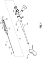
FIG. 1 is a perspective view of a hysteroscopic system provided in accordance with the present disclosure including a working device, a hysteroscope, and an ultrasound device; -
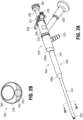
FIG. 2A is a perspective view of the hysteroscope of the hysteroscopic system ofFIG. 1 ; -
FIG. 2B is a transverse, cross-sectional view taken across section line "2B-2B" ofFIG. 2A ; -
FIG. 3 is a perspective view of the ultrasound device of the hysteroscopic system ofFIG. 1 ; -
FIG. 4 is a perspective view illustrating the hysteroscope inserted through the ultrasound device; -
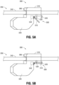
FIGS. 5A and 5B are perspective views of the ultrasound device disposed on the hysteroscope with a locking mechanism in unlocked and locked conditions, respectively; -
FIGS. 6A-6C are perspective views of the ultrasound device disposed on the hysteroscope with various different sized spacers positioning the ultrasound device relative to the hysteroscope; -
FIGS. 7A and 7B are perspective views of another ultrasound device provided in accordance with the present disclosure disposed on the hysteroscope with a locking mechanism in unlocked and locked conditions, respectively; -
FIGS. 8A and 8B are perspective views illustrating longitudinal sliding of a first portion of the ultrasound device relative to a second portion of the ultrasound device and the hysteroscope; -
FIGS. 9A and 9B are perspective views illustrating axial rotation of a first portion of the ultrasound device relative to a second portion of the ultrasound device and the hysteroscope of about a longitudinal axis of the hysteroscope; -
FIGS. 10A and 10B are perspective views illustrating pivoting of a first portion of the ultrasound device relative to a second portion of the ultrasound device and the hysteroscope to tilt the first portion relative to the second portion and the hysteroscope; -
FIG. 11 is a side, partial cross-sectional view of the hysteroscopic system ofFIG. 1 in use wherein the ultrasound device is positioned adjacent the cervix, the hysteroscope extends through the ultrasound device and through the cervix into the uterus, and the working device extends from the hysteroscope into the uterus; and -
FIG. 12 is a schematic illustration of a robotic surgical system configured for use in accordance with the aspects of the present disclosure. - Referring to
FIG. 1 , a hysteroscopic system provided in accordance with the present disclosure is shown generally identified byreference numeral 10 including aworking device 100, e.g., a tissue resection device, an ablation device, a biopsy device, etc.; ahysteroscope 200; and anultrasound device 300.Ultrasound device 300 is configured for transvaginal insertion into position adjacent to or in abutment with tissue surrounding the cervix of a patient (e.g., a human patient).Hysteroscope 200 is configured for insertion throughultrasound device 300 and the cervix into the uterus of the patient.Working device 100 is configured for insertion throughhysteroscope 200 and into the uterus of the patient to perform a surgical procedure in the uterine cavity and/or within the uterine wall. Although described herein with respect to a hysteroscopic system for performing a surgical procedure within the uterus (e.g., within the uterine cavity and/or within the uterine wall), the aspects and features of the present disclosure are also applicable for use in other endoscopic procedures such as ultrasound guided endoscopic surgical procedures. - Working
device 100, as noted above, may be a tissue resection device, an ablation device, a biopsy device, or other suitable working device configured for use on or within the uterus. With respect to a tissue resection device, for example, workingdevice 100 includes ahousing 110, ashaft 120, a cuttingmember 130, adrive mechanism 140, anoutflow port 150, and acable 160.Housing 110 houses drivemechanism 140 therein and functions as a handle to enable a user to grasp workingdevice 100.Drive mechanism 140 includes a motor and is operably coupled to cuttingmember 130 to drive rotation and/or translation of cuttingmember 130 relative toshaft 120.Drive mechanism 140 is adapted to connect to a control unit (not shown) viacable 160 for powering and controlling the motor, although workingdevice 100 may alternatively be battery powered or manually powered. A suction source (not shown) incorporated into the control unit (not shown), or any other suitable vacuum creating mechanism, may also be provided to facilitate withdrawal of fluid, tissue, and debris through workingdevice 100 andoutflow port 150. -
Shaft 120 of workingdevice 100 extends distally fromhousing 110 and, in aspects, is stationary relative tohousing 110, although other configurations are also contemplated. Cuttingmember 130 extends throughshaft 120 and is rotatable and/or translatable relative toshaft 120. More specifically, cuttingmember 130 is operably coupled to drivemechanism 140 for driving the rotation and/or translation of cuttingmember 130 relative toshaft 120 for cutting and removing tissue. A distal portion of cuttingmember 130 is exposed via an open distal end of shaft 120 (as shown) and/or a window defined throughshaft 120. - In use of working
device 100, upon activation, tissue is drawn intoshaft 120 and/or cuttingmember 130. As tissue is drawn intoshaft 120 and/or cuttingmember 130, the tissue is resected via the rotation and/or translation of cuttingmember 130 relative toshaft 120, thus enabling the resected tissue to be drawn proximally throughshaft 120 and/or cuttingmember 130, along with fluid and debris. The resected tissue, fluid, and debris are drawn proximally throughoutflow port 150 and outflow tubing (not shown) and, ultimately, to one or more collection canisters of a fluid management system (not shown). - With additional reference to
FIGS. 2A and 2B ,hysteroscope 200 includes ahandle 220, ashaft 240, and a removable outflow and/orinstrument working channel 260. Handle 220 ofhysteroscope 200 includes ahousing 222, alight post 224, inflow andoutflow ports outflow valves arm 230.Housing 222 defines a generally cylindrical-shaped configuration extending along a longitudinal axis defined byhysteroscope 200.Light post 224 extends fromhousing 222 and is configured to connect to a light source, e.g., to illuminate a distal end ofshaft 240 via a plurality of fiber optic strands 232 (FIG. 2A ) coupled tolight post 224 and extending throughshaft 240 to the distal end ofshaft 240. Inflow andoutflow ports shaft 240 to/from the internal surgical site, e.g., the uterus. Inflow andoutflow valves outflow ports Arm 230 is configured to connect to an imaging device, e.g., a camera, to capture images received via optics 234 (FIG. 2A ) extending throughshaft 240 to the distal end ofshaft 240 and, thus, enable display of a video image of the internal surgical site as captured byoptics 234. -
Shaft 240 ofhysteroscope 200 extends distally fromhandle 220 along the longitudinal axis ofhysteroscope 200 and includes including aproximal portion 242 having a first diameter, adistal portion 244 having a second, smaller diameter, and afirst transition portion 246a disposed between proximal anddistal portions distal portions second transition portion 246b may be disposed betweenproximal portion 242 ofshaft 240 andhousing 222 ofhandle 220 to provide a transition tapering from the first diameter ofproximal portion 242 ofshaft 240 to a third diameter ofhousing 222 ofhandle 220 that is greater than the first diameter. -
Distal portion 244 ofshaft 240 ofhysteroscope 200, defining a relatively small diameter, is configured for insertion transvaginally through the cervix and into the uterus. The relatively small diameter ofdistal portion 244 ofshaft 240 reduces pain and discomfort for the patient and also provides increased flexibility compared to the relatively large diameterproximal portion 244, thus facilitating insertion through the cervix and into the uterus.Proximal portion 242 ofshaft 240 ofhysteroscope 200, defining a relatively large diameter, is configured for insertion transvaginally through the vaginal introitus and into the vaginal canal, but not through the cervix. The relatively large diameterproximal portion 242 provides increased structural support toshaft 240 ofhysteroscope 200.Housing 222 ofhandle 220 ofhysteroscope 220, defining the largest diameter, is configured to remain externally of the patient, to facilitate operating, manipulating, and/or supportinghysteroscope 200.Transition portion 246a ofshaft 240 ofhysteroscope 200 facilitates atraumatic insertion of relatively large diameterproximal portion 242 ofshaft 240 ofhysteroscope 200 through the vaginal introitus and into the vaginal canal and atraumatic contact with the cervix. Likewise,transition portion 246b ofshaft 240 ofhysteroscope 200 facilitates atraumatic contact with the vaginal introitus. -
Shaft 240 includes, as noted above, the plurality offiber optic strands 232 andoptics 234 extending therethrough.Shaft 240 further includes a generally D-shapedinflow channel 248 extending therethrough.Inflow channel 248 fluidly communicates withinflow port 226. The plurality offiber optic strands 232 andoptics 234 extend throughshaft 240 externally ofinflow channel 248. Workingchannel 260 extends throughinflow channel 248 and is removable therefrom, although in aspects, workingchannel 260 is integral withshaft 240. Workingchannel 260 functions as an outflow and/or instrument channel that fluidly communicates withoutflow port 228. In aspects,channels channel 248 is utilized for outflow andchannel 260 is utilized for inflow. In aspects, workingchannel 260 includes aproximal seal assembly 262 configured to establish a seal about an instrument inserted through workingchannel 260. -
Distal tip 250 ofshaft 240 includes a partially-slanted configuration whereby the plurality offiber optic strands 232 andoptics 234 end at a perpendicular distal surface while theinflow channel 248 defines a slanted distal surface that is angled proximally from the distal surface of the plurality offiber optic strands 232 andoptics 234. - Referring to
FIGS. 3 and4 ,ultrasound device 300 includes acollar 310, abody 320 extending fromcollar 310, anultrasound sensor assembly 330 disposed withinbody 320, and acable 340 configured to connectultrasound sensor assembly 330 to an ultrasound console (not shown), e.g., viawires 350 extending fromultrasound sensor assembly 330 throughbody 320 and/orcollar 310 and throughcable 340. In aspects,ultrasound device 300 is configured for full insertion (with the exception of cable 340) transvaginally through the vaginal introitus and into the vaginal canal for positioning adjacent to or in contact with tissue surrounding the cervix. This configuration enables ultrasound imaging of the cervix, uterus, and/or surrounding tissue, while minimizing the overall diameter of instrumentation extending through the vaginal introitus (onceultrasound device 300 is passed through the vaginal introitus and into the vaginal canal). -
Collar 310 ofultrasound device 300 defines alongitudinal lumen 360 extending throughcollar 310.Longitudinal lumen 360 is configured to permit passage of at least a portion of an endoscope device throughcollar 310. For example,longitudinal lumen 360 ofcollar 310 may be configured to receivedistal portion 244 ofshaft 240 ofhysteroscope 200 therethrough.Longitudinal lumen 360 may additionally or alternatively be configured to permit passage of other instrumentation, e.g., one or more working devices, therethrough. - In aspects,
longitudinal lumen 360 defines an internal diameter greater than the second, smaller diameter ofdistal portion 244 ofshaft 240 but smaller than the first, larger diameter ofproximal portion 242 ofshaft 240. Thus,collar 310 ofultrasound device 300 is slidably positionable aboutdistal portion 244 ofshaft 240 of hysteroscope 200 (e.g., overdistal tip 250 of shaft 240) but is inhibited from proximal sliding overfirst transition portion 246a ofshaft 240 ofhysteroscope 200 ontoproximal portion 242 ofshaft 240 ofhysteroscope 200. In aspects, in addition to longitudinal sliding alongdistal portion 244 ofshaft 240 ofhysteroscope 200,collar 310 may be configured to rotate aboutdistal portion 244 ofshaft 240 ofhysteroscope 200, e.g., about a longitudinal axis ofhysteroscope 200. -
Collar 310 defines a longitudinal length, in aspects, not greater than about 50% of a length ofshaft 240 ofhysteroscope 200; in other aspects, not greater than about 40% of a length ofshaft 240 ofhysteroscope 200; in still other aspects, not greater than about 30% of a length ofshaft 240 ofhysteroscope 200; or, in yet other aspects, not greater than about 20% of a length ofshaft 240 ofhysteroscope 200. In aspects,collar 310 defines a longitudinal length not greater than about 50% of a length ofdistal portion 244 ofshaft 240 ofhysteroscope 200; in other aspects, not greater than about 40% of a length ofdistal portion 244 ofshaft 240 ofhysteroscope 200; or, in still yet other aspects, not greater than about 30% of a length ofdistal portion 244 ofshaft 240 ofhysteroscope 200. - Continuing with reference to
FIGS. 3 and4 ,body 320 ofultrasound device 300 may be configured as afoot 322 depending from and protruding distally relative tocollar 310 ofultrasound device 300. Thus, withshaft 240 ofhysteroscope 200 extending through and distally fromcollar 310,foot 322 extends alongside a portion ofshaft 240 ofhysteroscope 200 that extends distally fromcollar 310. More specifically,foot 322 may be fixed relative tocollar 310 and oriented such thatfoot 322 extends in substantially parallel orientation relative toshaft 240 ofhysteroscope 200. Alternatively,foot 322 may be fixed relative tocollar 310 and oriented such thatfoot 322 extends at an angle relative tocollar 310 and thus,shaft 240 ofhysteroscope 200. This angle, in aspects, may be from about 10 degrees to about 70 degrees, although other orientations and/or angles offoot 322 relative tocollar 310 are also contemplated.Collar 310 andbody 320, in aspects, may be integrally formed, e.g., methodically from a single piece of material. In other aspects,body 320 is configured to slide, pivot, and/or rotate relative tocollar 310, thus permitting adjustment of the position and/or orientation offoot 322 relative tocollar 310 and thus,shaft 240 ofhysteroscope 200. -
Foot 322 defines a curved (e.g., convex) distally-facingsurface 324, thus providing an atraumatic interface for positioning distally-facingsurface 324 offoot 322 in contact with tissue, e.g., positioning distally-facingsurface 324 offoot 322 in contact with tissue surrounding the cervix (such as a vaginal fornix), to enableultrasound sensor assembly 330 to image the cervix, uterus, and/or surrounding tissue. -
Ultrasound sensor assembly 330 is disposed withinbody 320 ofultrasound device 300 and includes one ormore ultrasound sensors 332, e.g., ultrasound transducers, oriented towards distally-facingsurface 324 offoot 322 to emit ultrasound waves therefrom to enable ultrasound imaging of tissue, e.g., the cervix, uterus, and/or surrounding tissue. Eachultrasound sensor 332, more specifically, is configured to emit ultrasound waves, e.g., high-frequency sound waves, and to receive echoed waves produced by the reflection of the ultrasound waves against the various tissue structures encountered. The echoed waves received by eachultrasound sensor 332 are output to an image processing unit (not shown), e.g., by way ofwires 360 extending throughbody 320 andcable 340. In aspects,ultrasound sensor assembly 330 includes one ormore ultrasound sensors 332 configured for 2D ultrasound imaging. In other aspects,ultrasound sensor assembly 330 includes a plurality ofultrasound sensors 332 forming an ultrasound sensor array that defines a portion of a circle, a portion of a polygon, a partially-polygonal, partially-arcuate configuration, or other suitable configuration to enable reconstruction of a 3D ultrasound image therefrom for 3D ultrasound imaging. - Referring to
FIGS. 5A and 5B , in aspects,ultrasound device 300 includes alocking mechanism 500 configured to releasably engagecollar 310 withshaft 240 ofhysteroscope 200 to thereby translationally and/orrotationally fix collar 310 ofultrasound device 300 relative toshaft 240 ofhysteroscope 200.Locking mechanism 500, more specifically, is transitionable between an unlocked condition (FIG. 5A ), whereincollar 310 andshaft 240 are longitudinally slidable and/or axially rotatable relative to one another, and a locked condition (FIG. 5B ), whereincollar 310 andshaft 240 are translationally and/or rotationally fixed relative to one another.Locking mechanism 500, as shown, includes alatch arm 510, acatch 520, and alock pin 530. In the unlocked condition oflocking mechanism 500, as shown inFIG. 5A ,latch arm 510 is disengaged fromcatch 520 andlock pin 530 is displaced fromlongitudinal lumen 360 ofcollar 310, thus permitting longitudinal sliding and/or axial rotation ofshaft 240 withinlongitudinal lumen 360 and relative tocollar 310. In the locked condition oflocking mechanism 500, as shown inFIG. 5B ,latch arm 510 is engaged withcatch 520, thereby urginglock pin 530 at least partially intolongitudinal lumen 360 ofcollar 310 to clampshaft 240 against an internal surface oflongitudinal lumen 360, thus inhibiting longitudinal sliding and/or axial rotation ofshaft 240 withinlongitudinal lumen 360 and relative tocollar 310. Other suitable locking mechanisms are also contemplated. - In aspects,
latch arm 510 is locally movable to transitionlocking mechanism 500 between the unlocked and locked conditions, e.g., via direct manipulation oflatch arm 510. In other aspects,locking mechanism 500 includes a lockingdrive assembly 540 disposed on or withinultrasound device 300 and configured to movelatch arm 510 to transitionlocking mechanism 500 between the unlocked and locked conditions. Lockingdrive assembly 540 may include mechanical drive components, e.g., gears, pulleys, cams etc., and/or electronic drive components, e.g., a motor. Lockingdrive assembly 540 may be configured for remote actuation via an electronic remote control (not shown) externally of the patient and wirelessly connected or wired (e.g., via wires extending through cable 340 (FIG. 3 )) to lockingdrive assembly 540. Alternatively, lockingdrive assembly 540 may be configured for remote actuation via a mechanical actuator coupled to lockingdrive assembly 540 and extending through cable 340 (FIG. 3 ) for actuation externally of the patient. - Turning to
FIGS. 6A-6C , as noted above, in aspects,collar 310 ofultrasound device 300 is slidably positionable aboutdistal portion 244 ofshaft 240 ofhysteroscope 200 but is inhibited from proximal sliding overfirst transition portion 246a ofshaft 240 ofhysteroscope 200 ontoproximal portion 242 ofshaft 240 ofhysteroscope 200. In these and other aspects, one ormore spacers FIGS. 6A-6C , respectively) may be provided to limit the relative longitudinal motion betweencollar 310 ofultrasound device 300 anddistal portion 244 ofshaft 240 ofhysteroscope 200. More specifically, rather than permittingshaft 240 ofhysteroscope 200 to advance distally throughcollar 310 ofultrasound device 300 to a position whereincollar 310 is disposed at (or beyond)first transition portion 246a ofshaft 240, spacers 600a, 600b, 600c are positionable aboutdistal portion 244 ofshaft 240 betweenfirst transition portion 246a andcollar 310 to limit insertion ofshaft 240 ofhysteroscope 200 throughcollar 310, e.g., due to the abutment ofcollar 310 with adistal end - As shown in
FIGS. 6A-6C , spacers 600a, 600b, 600c are disposed aboutdistal portion 244 ofshaft 240 and each includes aproximal end first transition portion 246a ofshaft 240 and adistal end Spacer 600a defines a first length extending between proximal anddistal ends spacer 600b defines a second length, greater than the first length, extending between proximal anddistal ends spacer 600c defines a third length, greater than the second length, extending between proximal anddistal ends distal tip 250 ofshaft 240 ofhysteroscope 200 is permitted to extend a first distance fromcollar 310 ofultrasound device 300 when spacer 600a is used;distal tip 250 ofshaft 240 ofhysteroscope 200 is permitted to extend a second distance, less than the first distance, fromcollar 310 ofultrasound device 300 whenspacer 600b is used; anddistal tip 250 ofshaft 240 ofhysteroscope 200 is permitted to extend a third distance, less than the second distance, fromcollar 310 ofultrasound device 300 whenspacer 600c is used. Accordingly, withbody 320 ofultrasound device 300 abutting tissue adjacent to or surrounding the cervix (and, thus, disposed in substantially fixed position relative to the patient's anatomy), and with anappropriate spacer shaft 240 ofhysteroscope 200 is insertable through the cervix and into the uterus can be set. - With reference to
FIGS. 7A and 7B , anotherultrasound device 700 provided in accordance with the present disclosure is shown.Ultrasound device 700 may be similar to and include any of the features of ultrasound device 300 (FIG. 3 ), except as explicitly contradicted below. As such, only differences betweenultrasound device 700 and ultrasound device 300 (FIG. 3 ) are described in detail below while similarities are summarily described or omitted entirely. -
Ultrasound device 700 includes asleeve 710, abody 720 extending fromsleeve 710, anultrasound sensor assembly 730 disposed withinbody 720, and a cable (not shown) extending through or alongsleeve 710 and configured to connectultrasound sensor assembly 730 to an ultrasound console (not shown). -
Sleeve 710 ofultrasound device 700 defines a longitudinal lumen extending therethrough that is configured to permit passage of at least a portion of an endoscope device throughsleeve 710. For example,sleeve 710 may be configured to receive at least a portion ofshaft 240 ofhysteroscope 200. -
Body 720 ofultrasound device 700 may be configured as afoot 722 depending from and protruding distally relative tosleeve 710 ofultrasound device 700.Foot 722 is configured for positioning in contact with tissue surrounding the cervix (such as a vaginal fornix), to enableultrasound sensor assembly 730 to image the cervix, uterus, and/or surrounding tissue. -
Sleeve 710 is configured such that, withfoot 722 contacting tissue surrounding the cervix (such as a vaginal fornix),sleeve 710 extends proximally through the vaginal canal and vaginal introitus externally of the patient. Further, aproximal end 712 of sleeve may be configured to limit the relative longitudinal motion betweensleeve 710 ofultrasound device 700 andshaft 240 ofhysteroscope 200. More specifically, upon insertion ofshaft 240 ofhysteroscope 200 distally throughsleeve 710,second transition portion 246b ofshaft 240 ofhysteroscope 200 contactsproximal end 712 ofsleeve 710 and inhibits further distal advancement ofshaft 240 ofhysteroscope 200. Accordingly, withultrasound device 700 abutting tissue adjacent to or surrounding the cervix (and, thus, disposed in substantially fixed position relative to the patient's anatomy),sleeve 710 defines the extent to whichshaft 240 ofhysteroscope 200 is insertable through the cervix and into the uterus.Sleeve 710, in aspects, is configured to telescope or is otherwise variable in length and/ordifferent length sleeves 710 may be provided, thus enabling a selection of asleeve 710 according to a desired amount of extension ofshaft 240 ofhysteroscope 200 through the cervix and into the uterus. - Continuing with reference to
FIGS. 7A and 7B , in aspects,ultrasound device 700 further includes alocking mechanism 750 configured to releasably engagesleeve 710 withshaft 240 ofhysteroscope 200 to thereby translationally and/orrotationally fix sleeve 710 ofultrasound device 700 relative toshaft 240 ofhysteroscope 200.Locking mechanism 750 may include a threadedpassage 752 and a threadedset screw 754 configured for threaded engagement with threadedpassage 752. More specifically, rotation of threaded setscrew 754 relative to threadedpassage 752 in a first direction advances threaded setscrew 754 radially inwardly and rotation of threaded setscrew 754 in a second, opposite direction retracts threaded setscrew 754 radially outwardly. Thus, threaded setscrew 754 may be moved between a retracted position, corresponding to an unlocked condition (FIG. 7A ), whereinshaft 240 is longitudinally slidable and/or axially rotatable relative tosleeve 710, and an inserted position, corresponding to a locked condition (FIG. 7B ), wherein threadedset screw 754 clampsshaft 240 against an internal surface ofsleeve 710, thus inhibiting longitudinal sliding and/or axial rotation ofshaft 240 relative tosleeve 710. Other suitable locking mechanisms are also contemplated. - Turning to
FIGS. 8A-10B , in addition to an entirety ofultrasound device 300 being longitudinally slidable along and/or axially rotatable aboutshaft 240 ofhysteroscope 200 and, in aspects, lockable in longitudinal and/or rotational position aboutshaft 240 ofhysteroscope 200,ultrasound device 300 may configured to enable relative motion betweencollar 310 andbody 320. More specifically, as detailed below,body 320 may be configured to longitudinally translate relative to collar 310 (FIGS. 8A and 8B ), rotate about collar 310 (FIGS. 9A and 9B ), and/or pivot (or tilt) relative to collar 30 (FIGS. 10A and 10B ). - Referring to
FIGS. 8A and 8B ,ultrasound device 300 may include atranslation mechanism 800 configured to enablebody 320 to longitudinally translate relative tocollar 310.Translation mechanism 800 may include, for example aguide rail 810 disposed on one of collar 310 (as shown) orbody 320 and acarriage 820 disposed on the other ofcollar 310 or body 320 (as shown).Carriage 820 is slidably engaged withguide rail 810 to enable translation ofcarriage 820 relative to guiderail 810 and, thus, translation ofbody 320 relative tocollar 310 between, for example, a retracted position (FIG. 8A ), whereinbody 320 protrudes distally a relatively small distance relative to collar 310 (or does not protrude distally from collar 31), and an extended position (FIG. 8B ) whereinbody 320 protrudes distally a relatively large distance relative tocollar 310. In aspects,translation mechanism 800 includes a discrete or continuous locking mechanism (not shown) to enable locking ofbody 320 relative tocollar 310 at defined positions or at any suitable position, respectively. -
Translation mechanism 800 may further include adrive assembly 840 including mechanical drive components, e.g., gears, pulleys, cams etc., and/or electronic drive components, e.g., a motor, for driving translation ofbody 320 relative tocollar 310.Drive assembly 840 may be configured for remote actuation via an electronic remote control (not shown) externally of the patient and wirelessly connected or wired to driveassembly 840. Alternatively, drive assembly 840 may be configured for remote actuation via a mechanical actuator coupled to driveassembly 840 and extending outside of the patient for actuation externally of the patient. - As shown in
FIGS. 9A and 9B ,ultrasound device 300 may include arotation mechanism 900 configured to enablebody 320 to rotate aboutcollar 310.Rotation mechanism 900 may include, for example, anextension 910 extending frombody 320 and disposed aboutcollar 310.Rotation mechanism 900 may further include abearing 920 disposed betweencollar 310 andextension 910 to enable rotation ofextension 910 and, thus,body 320 about a longitudinal axis of collar 310 (and/or a longitudinal axis ofshaft 240 of hysteroscope 200). In aspects,rotation mechanism 900 includes a discrete or continuous locking mechanism (not shown) to enable locking ofbody 320 relative tocollar 310 at defined positions or at any suitable position, respectively. -
Rotation mechanism 900 may further include adrive assembly 940 including mechanical drive components, e.g., gears, pulleys, cams etc., and/or electronic drive components, e.g., a motor, for driving rotation ofbody 320 relative tocollar 310.Drive assembly 940 may be configured for remote actuation via an electronic remote control (not shown) externally of the patient and wirelessly connected or wired to driveassembly 940. Alternatively, drive assembly 940 may be configured for remote actuation via a mechanical actuator coupled to driveassembly 940 and extending outside of the patient for actuation externally of the patient. - With reference to
FIGS. 10A and 10B ,ultrasound device 300 may include apivot mechanism 1000 configured to enablebody 320 to pivot (or tilt) relative tocollar 310.Pivot mechanism 1000 may include, for example, ahinge 1010pivotably coupling body 320 andcollar 310 with one another. In aspects,pivot mechanism 1000 includes a discrete or continuous locking mechanism (not shown) to enable locking ofbody 320 relative tocollar 310 at defined positions or at any suitable position, respectively. -
Pivot mechanism 1000 may further include adrive assembly 1040 including mechanical drive components, e.g., gears, pulleys, cams etc., and/or electronic drive components, e.g., a motor, for driving pivoting ofbody 320 relative tocollar 310.Drive assembly 1040 may be configured for remote actuation via an electronic remote control (not shown) externally of the patient and wirelessly connected or wired to driveassembly 1040. Alternatively,drive assembly 1040 may be configured for remote actuation via a mechanical actuator coupled to driveassembly 1040 and extending outside of the patient for actuation externally of the patient. - Turning to
FIG. 11 ,hysteroscopic system 10 is shown in use whereinultrasound device 300 is inserted trans-vaginally through the vaginal introitus and into the vaginal canal "V" such that the entirety ofultrasound device 300 is disposed within the vaginal canal "V" withbody 320, includingultrasound sensor assembly 330, positioned adjacent or in abutment with tissue surrounding the cervix "C," e.g., at a vaginal fornix "VF," to enable ultrasound imaging of a field of view "F1" including the uterus "U," uterine wall "W," and surrounding tissue. In this position,collar 310 is substantially aligned with the cervix "C." In aspects,ultrasound device 300 may be manipulated entirely or via movement ofbody 320 relative tocollar 310, to achieve the above or other suitable positioning. - Continuing with reference to
FIG. 11 ,distal portion 244 ofshaft 240 ofhysteroscope 200 extends throughcollar 310 ofultrasound device 300 through the cervix "C" and into the uterus "U." In this manner,hysteroscope 200 may be utilized for visualization within the uterus "U," e.g., providing a field of view "F2," together with or separately from the ultrasound imaging.Hysteroscope 200 may also be used for the introduction of fluid into and/or the removal of fluid from the uterus "U" and/or for passage of workingdevice 100, e.g., a tissue resection device, ablation device, biopsy device, etc., therethrough and into the uterus "U" to perform one or more hysteroscopic tasks therein (e.g., within the uterus "U") or therethrough (e.g., within the uterine wall "W"). The use of ultrasound imaging of the uterus "U" from the exterior thereof and/or visualization of the uterus "U" from within the uterine cavity provides increased visibility for performing various different hysteroscopic tasks without the need to swap out instruments supporting different imaging modalities and/or providing different imaging perspectives. - With reference to
FIG. 12 , a roboticsurgical system 1200 configured for use in accordance with the present disclosure is shown. Aspects and features of roboticsurgical system 1200 not germane to the understanding of the present disclosure are omitted to avoid obscuring the aspects and features of the present disclosure in unnecessary detail. - Robotic
surgical system 1200 generally includes a plurality ofrobot arms 1202, 1203 (although two robot arms are shown, only one or more than tworobot arms operating console 1205 coupled withcontrol device 1204.Operating console 1205 may include adisplay device 1206, which may be set up in particular to display three-dimensional images; andmanual input devices 1207, 1208, by means of which a person, e.g., a surgeon, may be able to telemanipulaterobot arms surgical system 1200 may be configured for use on apatient 1213 lying on a patient table 1212. Roboticsurgical system 1200 may further include adatabase 1214, in particular coupled to controldevice 1204, in which are stored, for example, pre-operative data frompatient 1213 and/or anatomical atlases. - Each of the
robot arms FIG. 1 , the surgical tools "ST" may include, for example, workingdevice 100,hysteroscope 200,ultrasound device 300, etc., thus providing any of the above detailed functionality ofsystem 10 on a roboticsurgical system 1200. - Continuing with reference to
FIG. 12 ,robot arms device 1204. The motors, for example, may be rotational drive motors configured to provide rotational inputs to accomplish a desired task or tasks.Control device 1204, e.g., a computer, may be configured to activate the motors, in particular by means of a computer program, in such a way thatrobot arms manual input devices 1207, 1208, respectively.Control device 1204 may also be configured in such a way that it regulates the movement ofrobot arms -
Control device 1204, more specifically, may control one or more of the motors based on rotation, e.g., controlling to rotational position using a rotational position encoder (or Hall effect sensors or other suitable rotational position detectors) associated with the motor to determine a degree of rotation output from the motor and, thus, the degree of rotational input provided. Alternatively or additionally,control device 1204 may control one or more of the motors based on torque, current, or in any other suitable manner. - While several aspects of the disclosure have been shown in the drawings, it is not intended that the disclosure be limited thereto, as it is intended that the disclosure be as broad in scope as the art will allow and that the specification be read likewise. Therefore, the above description should not be construed as limiting, but merely as exemplifications of particular aspects. Those skilled in the art will envision other modifications within the scope and spirit of the claims appended hereto.
- The invention may be described by reference to the following numbered paragraphs :-
- 1. A transvaginal ultrasound device, comprising:
- a collar defining a longitudinal lumen configured to receive a shaft for slidably positioning the collar about the shaft;
- a body depending from the collar and protruding distally relative to the collar; and
- an ultrasound sensor assembly disposed within the body, the ultrasound sensor assembly configured for ultrasound imaging,
- wherein the collar and the body are configured for full insertion through a vaginal introitus and into a vaginal canal of a human patient for positioning the longitudinal lumen of the collar in substantial alignment with a cervix of the human patient to enable the shaft to extend through the cervix and into a uterus of the human patient.
- 2. The transvaginal ultrasound device according to
paragraph 1, further comprising a locking mechanism configured to releasably lock the collar about the shaft to at least one of slidably or rotationally fix the collar relative to the shaft. - 3. The transvaginal ultrasound device according to
paragraph 2, wherein the locking mechanism includes a locking drive assembly configured to transition the locking mechanism between a locked condition and an unlocked condition. - 4. The transvaginal ultrasound device according to
paragraph 1, wherein the body is fixed relative to the collar. - 5. The transvaginal ultrasound device according to
paragraph 1, wherein the body is movable relative to the collar. - 6. The transvaginal ultrasound device according to paragraph 5, wherein the body is rotatable relative to the collar.
- 7. The transvaginal ultrasound device according to paragraph 5, wherein the body is slidable relative to the collar.
- 8. The transvaginal ultrasound device according to paragraph 5, wherein the body is pivotable relative to the collar.
- 9. The transvaginal ultrasound device according to paragraph 5, further comprising a drive assembly configured to move the body relative to the collar.
- 10. A hysteroscopic surgical system, comprising:
- a hysteroscope including a handle and a shaft extending distally from the handle; and
- an ultrasound device, including:
- a collar defining a longitudinal lumen configured to receive the shaft for slidably positioning the collar about the shaft;
- a body depending from the collar and protruding distally relative to the collar; and
- an ultrasound sensor assembly disposed within the body, the ultrasound sensor assembly configured for ultrasound imaging,
- wherein the collar and the body are configured for positioning within a vaginal canal of a human patient for positioning the longitudinal lumen of the collar in substantial alignment with a cervix of the human patient to enable the shaft to extend through the cervix and into a uterus of the human patient.
- 11. The hysteroscopic surgical system according to
paragraph 10, wherein the shaft of the hysteroscope includes a first portion defining a first diameter and a second portion defining a second diameter greater than the first diameter, and wherein the longitudinal lumen of the collar defines a third diameter greater than the first diameter but less than the second diameter to enable slidable positioning the collar about the first portion of the shaft and inhibit sliding of the collar onto the second portion of the shaft. - 12. The hysteroscopic surgical system according to
paragraph 10, further comprising:
a spacer configured for positioning about the shaft of the hysteroscope proximally of the collar, the spacer configured to define an extent of distal insertion of the shaft of the hysteroscope through the collar. - 13. The hysteroscopic surgical system according to paragraph 12, wherein the spacer is configured for positioning about the shaft of the hysteroscope between the collar and a transition defined along the shaft.
- 14. The hysteroscopic surgical system according to
paragraph 10, further comprising a locking mechanism configured to releasably lock the collar about the shaft to at least one of slidably or rotationally fix the collar relative to the shaft. - 15. The hysteroscopic surgical system according to paragraph 14, wherein the locking mechanism includes a locking drive assembly configured to transition the locking mechanism between a locked condition and an unlocked condition.
- 16. The hysteroscopic surgical system according to
paragraph 10, wherein the body is fixed relative to the collar. - 17. The hysteroscopic surgical system according to
paragraph 10, wherein the body is movable relative to the collar. - 18. The hysteroscopic surgical system according to paragraph 17, wherein the body is rotatable relative to the collar.
- 19. The transvaginal ultrasound device according to paragraph 17, wherein the body is slidable relative to the collar.
- 20. The transvaginal ultrasound device according to paragraph 17, wherein the body is pivotable relative to the collar.
Claims (14)
- A transvaginal ultrasound device, comprising:a collar defining a longitudinal lumen configured to receive a shaft for slidably positioning the collar about the shaft;a body depending from the collar and protruding distally relative to the collar; andan ultrasound sensor assembly disposed within the body, the ultrasound sensor assembly configured for ultrasound imaging,wherein the collar and the body are configured for full insertion through a vaginal introitus and into a vaginal canal of a human patient for positioning the longitudinal lumen of the collar in substantial alignment with a cervix of the human patient to enable the shaft to extend through the cervix and into a uterus of the human patient.
- The transvaginal ultrasound device according to claim 1, further comprising a locking mechanism configured to releasably lock the collar about the shaft to at least one of slidably or rotationally fix the collar relative to the shaft.
- The transvaginal ultrasound device according to claim 2, wherein the locking mechanism includes a locking drive assembly configured to transition the locking mechanism between a locked condition and an unlocked condition.
- The transvaginal ultrasound device according to any preceding claim, wherein the body is fixed relative to the collar orwherein the body is movable relative to the collar, preferably wherein the body is rotatable relative to the collar, orwherein the body is slidable relative to the collar, orwherein the body is pivotable relative to the collar.
- The transvaginal ultrasound device according to claim 4, further comprising a drive assembly configured to move the body relative to the collar.
- A hysteroscopic surgical system, comprising:a hysteroscope including a handle and a shaft extending distally from the handle; andan ultrasound device, including:a collar defining a longitudinal lumen configured to receive the shaft for slidably positioning the collar about the shaft;a body depending from the collar and protruding distally relative to the collar; andan ultrasound sensor assembly disposed within the body, the ultrasound sensor assembly configured for ultrasound imaging,wherein the collar and the body are configured for positioning within a vaginal canal of a human patient for positioning the longitudinal lumen of the collar in substantial alignment with a cervix of the human patient to enable the shaft to extend through the cervix and into a uterus of the human patient.
- The hysteroscopic surgical system according to claim 6, wherein the shaft of the hysteroscope includes a first portion defining a first diameter and a second portion defining a second diameter greater than the first diameter, and wherein the longitudinal lumen of the collar defines a third diameter greater than the first diameter but less than the second diameter to enable slidable positioning the collar about the first portion of the shaft and inhibit sliding of the collar onto the second portion of the shaft.
- The hysteroscopic surgical system according to claim 6 or 7, further comprising:
a spacer configured for positioning about the shaft of the hysteroscope proximally of the collar, the spacer configured to define an extent of distal insertion of the shaft of the hysteroscope through the collar. - The hysteroscopic surgical system according to claim 8, wherein the spacer is configured for positioning about the shaft of the hysteroscope between the collar and a transition defined along the shaft.
- The hysteroscopic surgical system according to any of claims 6 to 9, further comprising a locking mechanism configured to releasably lock the collar about the shaft to at least one of slidably or rotationally fix the collar relative to the shaft.
- The hysteroscopic surgical system according to claim 10, wherein the locking mechanism includes a locking drive assembly configured to transition the locking mechanism between a locked condition and an unlocked condition.
- The hysteroscopic surgical system according to any of claims 6 to 11, wherein the body is fixed relative to the collar.
- The hysteroscopic surgical system according to any of claims 6 to 12, wherein the body is movable relative to the collar.
- The hysteroscopic surgical system according to claim 13, wherein the body is rotatable relative to the collar, orwherein the body is slidable relative to the collar, orwherein the body is pivotable relative to the collar.
Applications Claiming Priority (2)
| Application Number | Priority Date | Filing Date | Title |
|---|---|---|---|
| US202363459359P | 2023-04-14 | 2023-04-14 | |
| US18/499,156 US12690839B2 (en) | 2023-04-14 | 2023-10-31 | Devices, systems, and methods for transvaginal, ultrasound guided hysteroscopic surgical procedures |
Publications (1)
| Publication Number | Publication Date |
|---|---|
| EP4445848A1 true EP4445848A1 (en) | 2024-10-16 |
Family
ID=90731385
Family Applications (1)
| Application Number | Title | Priority Date | Filing Date |
|---|---|---|---|
| EP24169978.4A Pending EP4445848A1 (en) | 2023-04-14 | 2024-04-12 | Devices and systems for transvaginal, ultrasound guided hysteroscopic surgical procedures |
Country Status (2)
| Country | Link |
|---|---|
| US (1) | US12690839B2 (en) |
| EP (1) | EP4445848A1 (en) |
Citations (3)
| Publication number | Priority date | Publication date | Assignee | Title |
|---|---|---|---|---|
| US20080287916A1 (en) * | 2007-05-14 | 2008-11-20 | Agmon Arnon | Guide for placement of catheter into brain and a method of utilizing the same |
| US20150201964A1 (en) * | 2014-01-17 | 2015-07-23 | Gyrus Acmi, Inc., D.B.A. Olympus Surgical Technologies America | Integrated uterine manipulator and sensor and method |
| US20220401071A1 (en) * | 2020-01-07 | 2022-12-22 | Covidien Lp | Devices, systems, and methods for trans-vaginal, ultrasound-guided hysteroscopic surgical procedures |
Family Cites Families (58)
| Publication number | Priority date | Publication date | Assignee | Title |
|---|---|---|---|---|
| DE3921233A1 (en) | 1989-06-28 | 1991-02-14 | Storz Karl Gmbh & Co | ENDOSCOPE WITH A VIDEO DEVICE AT THE DISTAL END |
| US5351678A (en) | 1992-09-01 | 1994-10-04 | Citation Medical Corporation | Endoscope scope assembly for full hemisphere view |
| US6258083B1 (en) | 1996-03-29 | 2001-07-10 | Eclipse Surgical Technologies, Inc. | Viewing surgical scope for minimally invasive procedures |
| US5782752A (en) | 1996-04-05 | 1998-07-21 | Vista Medical Technologies, Inc. | Device for carrying two units in end to end disposition and for moving one of the units alongside the other of the units |
| JP3342021B2 (en) | 1997-10-17 | 2002-11-05 | サーコン コーポレーション | Medical device system that penetrates tissue |
| US6210330B1 (en) | 1999-08-04 | 2001-04-03 | Rontech Medical Ltd. | Apparatus, system and method for real-time endovaginal sonography guidance of intra-uterine, cervical and tubal procedures |
| US7520856B2 (en) | 1999-09-17 | 2009-04-21 | University Of Washington | Image guided high intensity focused ultrasound device for therapy in obstetrics and gynecology |
| US6736773B2 (en) | 2001-01-25 | 2004-05-18 | Scimed Life Systems, Inc. | Endoscopic vision system |
| US6884219B1 (en) | 2002-10-17 | 2005-04-26 | Rick L. Pruter | Method and disposable apparatus for guiding needles with an endocavity medical imaging device |
| US6960166B1 (en) | 2002-11-05 | 2005-11-01 | Irwin Lane Wong | Speculum having ultrasound probe |
| US20040097961A1 (en) | 2002-11-19 | 2004-05-20 | Vascular Control System | Tenaculum for use with occlusion devices |
| US6936048B2 (en) | 2003-01-16 | 2005-08-30 | Charlotte-Mecklenburg Hospital Authority | Echogenic needle for transvaginal ultrasound directed reduction of uterine fibroids and an associated method |
| US7404821B2 (en) | 2003-01-30 | 2008-07-29 | Vascular Control Systems, Inc. | Treatment for post partum hemorrhage |
| US7806827B2 (en) | 2003-03-11 | 2010-10-05 | General Electric Company | Ultrasound breast screening device |
| US6896657B2 (en) | 2003-05-23 | 2005-05-24 | Scimed Life Systems, Inc. | Method and system for registering ultrasound image in three-dimensional coordinate system |
| ES2552252T3 (en) | 2004-03-23 | 2015-11-26 | Boston Scientific Limited | Live View System |
| US8562516B2 (en) | 2004-04-14 | 2013-10-22 | Usgi Medical Inc. | Methods and apparatus for obtaining endoluminal access |
| WO2005112785A2 (en) | 2004-05-14 | 2005-12-01 | Ethicon Endo-Surgery, Inc. | Suture locking and cutting devices and methods |
| US9033870B2 (en) | 2004-09-24 | 2015-05-19 | Vivid Medical, Inc. | Pluggable vision module and portable display for endoscopy |
| US7621869B2 (en) | 2005-05-06 | 2009-11-24 | Nitesh Ratnakar | Next generation colonoscope |
| US7918795B2 (en) | 2005-02-02 | 2011-04-05 | Gynesonics, Inc. | Method and device for uterine fibroid treatment |
| US7517346B2 (en) | 2005-02-08 | 2009-04-14 | Boston Scientific Scimed, Inc. | Radio frequency ablation system with integrated ultrasound imaging |
| US8852111B2 (en) | 2005-09-02 | 2014-10-07 | Ultrasound Ventures, Llc | Ultrasound guidance system |
| US7874986B2 (en) | 2006-04-20 | 2011-01-25 | Gynesonics, Inc. | Methods and devices for visualization and ablation of tissue |
| US9357977B2 (en) | 2006-01-12 | 2016-06-07 | Gynesonics, Inc. | Interventional deployment and imaging system |
| US10058342B2 (en) | 2006-01-12 | 2018-08-28 | Gynesonics, Inc. | Devices and methods for treatment of tissue |
| US11259825B2 (en) | 2006-01-12 | 2022-03-01 | Gynesonics, Inc. | Devices and methods for treatment of tissue |
| US7815571B2 (en) | 2006-04-20 | 2010-10-19 | Gynesonics, Inc. | Rigid delivery systems having inclined ultrasound and needle |
| US20070213749A1 (en) | 2006-03-08 | 2007-09-13 | Olympus Medical Systems Corp. | Medical procedure performed inside abdominal cavity |
| US7794393B2 (en) | 2006-04-13 | 2010-09-14 | Larsen Dane M | Resectoscopic device and method |
| US8206300B2 (en) | 2008-08-26 | 2012-06-26 | Gynesonics, Inc. | Ablation device with articulated imaging transducer |
| US10595819B2 (en) | 2006-04-20 | 2020-03-24 | Gynesonics, Inc. | Ablation device with articulated imaging transducer |
| US8298145B2 (en) | 2006-08-01 | 2012-10-30 | Gynesonics, Inc. | Peri-capsular fibroid treatment |
| US7927272B2 (en) | 2006-08-04 | 2011-04-19 | Avantis Medical Systems, Inc. | Surgical port with embedded imaging device |
| US8088072B2 (en) | 2007-10-12 | 2012-01-03 | Gynesonics, Inc. | Methods and systems for controlled deployment of needles in tissue |
| US20090259097A1 (en) | 2008-04-09 | 2009-10-15 | Thompson Ronald J | Cannula visualization arrangement |
| US20140100558A1 (en) | 2012-10-05 | 2014-04-10 | Gregory P. Schmitz | Micro-articulated surgical instruments using micro gear actuation |
| US9332973B2 (en) | 2008-10-01 | 2016-05-10 | Covidien Lp | Needle biopsy device with exchangeable needle and integrated needle protection |
| US8262574B2 (en) | 2009-02-27 | 2012-09-11 | Gynesonics, Inc. | Needle and tine deployment mechanism |
| US20120245416A1 (en) | 2011-03-24 | 2012-09-27 | Tyco Healthcare Group Lp | Swing-out surgical camera |
| US20130046137A1 (en) | 2011-08-15 | 2013-02-21 | Intuitive Surgical Operations, Inc. | Surgical instrument and method with multiple image capture sensors |
| WO2013142978A1 (en) * | 2012-03-28 | 2013-10-03 | University Of Western Ontario | Actuator for moving an ultrasound probe |
| US9861336B2 (en) | 2012-09-07 | 2018-01-09 | Gynesonics, Inc. | Methods and systems for controlled deployment of needle structures in tissue |
| US20140128732A1 (en) | 2012-11-06 | 2014-05-08 | Cross Bay Medical, Inc. | Biopsy and sonography method and apparatus for assessing bodily cavities |
| DE102012025102A1 (en) | 2012-12-20 | 2014-06-26 | avateramedical GmBH | Endoscope with a multi-camera system for minimally invasive surgery |
| US20140228875A1 (en) | 2013-02-08 | 2014-08-14 | Nidus Medical, Llc | Surgical device with integrated visualization and cauterization |
| US10555719B2 (en) | 2013-03-12 | 2020-02-11 | St. Jude Medical Puerto Rico Llc | Ultrasound assisted needle puncture mechanism |
| AU2016222794B2 (en) | 2015-02-27 | 2021-01-07 | Covidien Lp | Expanding endoscope and method |
| US12186129B2 (en) | 2015-03-31 | 2025-01-07 | Boston Scientific Scimed, Inc. | Devices and methods for ultrasound imaging |
| US10716544B2 (en) | 2015-10-08 | 2020-07-21 | Zmk Medical Technologies Inc. | System for 3D multi-parametric ultrasound imaging |
| AU2017212365B2 (en) | 2016-01-27 | 2021-09-30 | Gynesonics, Inc. | Disposable sheath for ultrasound probe mounted on reusable needle structure |
| US20170319174A1 (en) | 2016-05-04 | 2017-11-09 | Covidien Lp | Systems for sensing position of imaging device |
| WO2017205468A1 (en) | 2016-05-24 | 2017-11-30 | Civco Medical Instruments Co., Inc. | Low profile endocavity needle guides |
| WO2018089523A1 (en) | 2016-11-11 | 2018-05-17 | Gynesonics, Inc. | Controlled treatment of tissue and dynamic interaction with, and comparison of, tissue and/or treatment data |
| KR20190086485A (en) | 2016-11-14 | 2019-07-22 | 지네소닉스, 인크. | Methods and systems for real-time planning and monitoring of ablation needle deployment within an organization |
| CN110831506A (en) | 2017-05-04 | 2020-02-21 | 杰尼索尼克斯公司 | Methods for monitoring ablation progress with Doppler ultrasound |
| EP3796835A4 (en) | 2018-05-21 | 2022-03-09 | Gynesonics, Inc. | PROCESSES AND SYSTEMS FOR IN SITU EXCHANGE |
| US12350097B2 (en) * | 2020-01-07 | 2025-07-08 | Covidien Lp | Devices, systems, and methods for trans-vaginal, ultrasound-guided hysteroscopic surgical procedures |
-
2023
- 2023-10-31 US US18/499,156 patent/US12690839B2/en active Active
-
2024
- 2024-04-12 EP EP24169978.4A patent/EP4445848A1/en active Pending
Patent Citations (3)
| Publication number | Priority date | Publication date | Assignee | Title |
|---|---|---|---|---|
| US20080287916A1 (en) * | 2007-05-14 | 2008-11-20 | Agmon Arnon | Guide for placement of catheter into brain and a method of utilizing the same |
| US20150201964A1 (en) * | 2014-01-17 | 2015-07-23 | Gyrus Acmi, Inc., D.B.A. Olympus Surgical Technologies America | Integrated uterine manipulator and sensor and method |
| US20220401071A1 (en) * | 2020-01-07 | 2022-12-22 | Covidien Lp | Devices, systems, and methods for trans-vaginal, ultrasound-guided hysteroscopic surgical procedures |
Also Published As
| Publication number | Publication date |
|---|---|
| US12690839B2 (en) | 2026-07-28 |
| US20240341722A1 (en) | 2024-10-17 |
Similar Documents
| Publication | Publication Date | Title |
|---|---|---|
| US12507986B2 (en) | Devices, systems, and methods for trans-vaginal, ultrasound-guided hysteroscopic surgical procedures | |
| JP5164553B2 (en) | Surgical treatment device | |
| JP4460857B2 (en) | Surgical system | |
| ES2280113T3 (en) | SURGICAL DEVICE FOR COLLECTION OF SOFT FABRIC. | |
| JP5816287B2 (en) | Micro-laparoscopic device and arrangement thereof | |
| US20030208187A1 (en) | Apparatus for positioning a medical instrument | |
| US20220401071A1 (en) | Devices, systems, and methods for trans-vaginal, ultrasound-guided hysteroscopic surgical procedures | |
| JP2010511487A (en) | Device for positioning / holding an instrument | |
| US20120150155A1 (en) | Instrument Control Device | |
| US9277932B2 (en) | Endoscopic scissors instrument with friction enhancing tissue stops | |
| US20230397807A1 (en) | Medical robotic system | |
| US11771305B2 (en) | Device with a working channel guiding element | |
| WO2021155319A1 (en) | Endoscopic surgical robots | |
| US20110178367A1 (en) | Endoscopic device with end effector mechanism | |
| US20110105838A1 (en) | Suction device for endoscopic instruments and method | |
| US20240341722A1 (en) | Devices, systems, and methods for transvaginal, ultrasound guided hysteroscopic surgical procedures | |
| US20230355324A1 (en) | Medical robotic system | |
| EP4327751A1 (en) | Devices, systems, and methods for trans-vaginal, ultrasound-guided hysteroscopic surgical procedures | |
| EP4445847A1 (en) | Devices and systems for ultrasound guided endoscopic surgical procedures | |
| US12514536B2 (en) | Systems and methods for tracking surgical instruments | |
| WO2026081879A1 (en) | Surgical instrument and surgical robot system | |
| CN121910475A (en) | Surgical robot | |
| HK40074707B (en) | Endoscopic surgical robots | |
| WO2025144131A1 (en) | A novel device for microsurgery | |
| WO2006002174A2 (en) | Apparatus for positioning a medical instrument relative to a patient |
Legal Events
| Date | Code | Title | Description |
|---|---|---|---|
| PUAI | Public reference made under article 153(3) epc to a published international application that has entered the european phase |
Free format text: ORIGINAL CODE: 0009012 |
|
| STAA | Information on the status of an ep patent application or granted ep patent |
Free format text: STATUS: REQUEST FOR EXAMINATION WAS MADE |
|
| 17P | Request for examination filed |
Effective date: 20240412 |
|
| AK | Designated contracting states |
Kind code of ref document: A1 Designated state(s): AL AT BE BG CH CY CZ DE DK EE ES FI FR GB GR HR HU IE IS IT LI LT LU LV MC ME MK MT NL NO PL PT RO RS SE SI SK SM TR |