TECHNICAL FIELD
-
The present application relates to the technical field of cooking appliances, and in particular to an air fryer.
BACKGROUND
-
An air fryer is a cooking appliance that uses a fan to blow high-temperature air into a pot to heat food. Due to the rapid dehydration of the food surface by the high-speed hot air to cause the Maillard reaction, the surface of the food becomes golden and crisp, achieving the deep-fried taste.
-
However, the air fryers currently on the market are less effective at heating food. For example, the hot air can only conduct convective heat exchange with one surface of the food (such as the upper surface of the food or the lower surface of the food) to form heating, which will cause uneven heating of the upper and lower surfaces of the food.
SUMMARY
-
Embodiments of the present application provide an air fryer to solve the above technical problems.
-
Embodiments of the present application achieve the above objects through the following technical solutions.
-
Embodiments of the present application provide an air fryer, the air fryer comprises:
- a pot body;
- a fan provided in the pot body; and
- a frying bucket assembly provided with a frying bucket, a first baking pan and a wind-shielding member; the first baking pan is located in the frying bucket and below the fan; a first air channel is formed above the first baking pan, and a second air channel is formed below the first baking pan; the wind-shielding member is located in the second air channel.
-
In some embodiments, the wind-shielding member reduces a speed of wind passing through the wind-shielding member so that the wind is easy to pass through the first baking pan from a position close to a center under a negative pressure formed by the fan.
-
In some embodiments, an air passage hole is formed on the first baking pan, and wind in the first air channel enters the second air channel through the air passage hole; the wind driven by the movement of the fan to flow in the second air channel acts on the wind entering the second air channel through the air passage hole.
-
In some embodiments, the wind driven by the movement of the fan to flow in the second air channel makes the wind entering the second air channel through the air passage hole move in a lower pressure position.
-
In some embodiments, the wind-shielding member comprises a plurality of wind-shielding ribs.
-
In some embodiments, the wind-shielding ribs are provided in a vertical plane, extending in a radial direction, and converging at a central position of the wind-shielding member.
-
In some embodiments, three or more of the wind-shielding ribs are provided and are arranged substantially in a cross.
-
In some embodiments, each of the wind-shielding ribs is provided with a curved extension.
-
In some embodiments, the wind-shielding member comprises:
- a raised portion provided on the frying bucket and located in the second air channel; and
- at least two wind-shielding ribs provided at interval around the raised portion.
-
In some embodiments, an interval is provided between an end, close to the wind-shielding rib, of each raised portion and the raised portion; and/or along a direction from the raised portion to the fan, the raised portion is of at least one of contracted conical shape, conical shape and hemispherical shape.
-
In some embodiments, a flow guide surface is formed on a bottom of the frying bucket, and the raised portion and at least two of the wind-shielding ribs are provided on the flow guide surface.
-
In some embodiments, along a direction from the wind-shielding rib to the fan, the flow guide surface is of at least one of constricted conical shape, conical shape, and spherical shape; or, the flow guide surface is a plane.
-
In some embodiments, the flow guide surface comprises a center line L1 extending in a vertical direction; the wind-shielding rib extends along a extension line L2 on a horizontal plane in a direction close to the center line, and the extension line does not intersect the center line; the extension line comprises a straight line and/or a curved line.
-
In some embodiments, the wind-shielding member is elongated.
-
In some embodiments, a length direction of the wind-shielding member is parallel to a width direction or a length direction or a diagonal line of the first baking pan.
-
In some embodiments, the wind-shielding member is arc-shaped or wave-shaped.
-
In some embodiments, a plurality of wind-shielding members are distributed around a center line of the first baking pan or are arranged at intervals along a width direction or a length direction of the first baking pan.
-
In some embodiments, the wind-shielding member is connected to a bottom of the frying bucket and a ventilation gap is provided between the wind-shielding member and a bottom wall of the first baking pan; and/or, the wind-shielding member is connected to a bottom of the first baking pan and a ventilation gap is provided between the wind-shielding member and the bottom of the frying bucket.
-
In some embodiments, a surface, facing the bottom of the frying bucket, of the bottom wall of the first baking pan is provided with an air guide channel, and the air guide channel is configured as the second air channel.
-
In some embodiments, the surface, facing the bottom of the frying bucket, of the bottom wall of the first baking pan is protruded with a plurality of air guide members, and the plurality of air guide members are distributed at intervals along an edge of the bottom wall.
-
In some embodiments, the frying bucket assembly further comprises:
- at least one second baking pan;
- the at least one second baking pan is located between the first baking pan and the fan; the first air channel is formed between the second baking pan and the first baking pan, and a third air channel is formed between the second baking pan and the fan.
-
In the air fryer provided by the embodiments of the present application, the fan is assembled in the pot body, and the first baking pan is placed in the frying bucket and below the fan. The first air channel is formed above the first baking pan, and the second air channel is formed below the first baking pan. The wind-shielding member is located in the second air channel. In this way, the hot air flow in the first air channel can heat the upper surface of the food, and the hot air flow in the second air channel can flow from the first baking pan to the food, heating the lower surface of the food, so that the upper and lower surfaces of the food are heated more evenly. Since the wind-shielding member is located in the second air channel, the wind-shielding member effectively reduces the circumferential rotation speed of the hot air flow by squeezing the hot air flow in the second air channel and then releasing it, which helps the negative pressure formed by the fan to quickly suck up the decelerated hot air and penetrate the food, and then improves the heat exchange effect of the second air channel, which helps to achieve a consistent heating effect on the upper and lower surfaces of the food.
BRIEF DESCRIPTION OF THE DRAWINGS
-
In order to more clearly illustrate the technical solutions in the embodiments of the present application, the following will briefly introduce the drawings that need to be used in the description of the embodiments. Obviously, the drawings in the following description are only some embodiments of the present application. For those skilled in the art, other drawings can also be obtained based on these drawings without any creative effort.
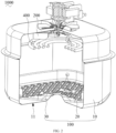
- FIG. 1 shows a schematic structural view of an air fryer according to an embodiment of the present application.
- FIG. 2 shows a partial structural schematic view of the air fryer in FIG. 1.
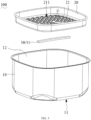
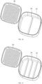
- FIG. 3 shows an exploded view of a frying bucket assembly of the air fryer according to an embodiment of the present application.
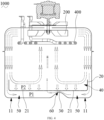
- FIG. 4 shows a schematic view of an air flow of the air fryer according to an embodiment of the present application.
- FIG. 5 shows another schematic view of the air flow of the air fryer according to an embodiment of the present application.
- FIG. 6 shows an exploded schematic view of a frying bucket assembly of the air fryer according to another embodiment of the present application.
- FIG. 7 shows an exploded schematic view of the frying bucket assembly of the air fryer according to another embodiment of the present application.
- FIG. 8 shows a schematic structural view of a frying bucket and a wind-shielding member of the air fryer according to an embodiment of the present application.
- FIG. 9 shows a schematic structural view of the frying bucket and the wind-shielding member of the air fryer according to another embodiment of the present application.
- FIG. 10 shows a structural schematic view of another perspective of the frying bucket and the wind-shielding member of the air fryer in FIG. 9 of the present application.
- FIG. 11 shows a schematic cross-sectional view of the frying bucket and the wind-shielding member of the air fryer along line XI in FIG. 10 of the present application.
- FIG. 12 shows a schematic structural view of a first baking pan of the frying bucket assembly of the air fryer according to an embodiment of the present application.
- FIG. 13 shows a schematic structural view of the first baking pan of the frying bucket assembly of the air fryer according to another embodiment of the present application.
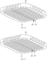
- FIG. 14 shows a schematic structural view of the first baking pan of the frying bucket assembly of the air fryer according to another embodiment of the present application.
- FIG. 15 shows a schematic structural view of the first baking pan of the frying bucket assembly of the air fryer according to another embodiment of the present application.
- FIG. 16 shows an exploded view of the frying bucket assembly of the air fryer according to another embodiment of the present application.
- FIG. 17 shows an exploded view of the frying bucket assembly of the air fryer according to another embodiment of the present application.
- FIG. 18 shows an exploded view of the frying bucket assembly of the air fryer according to another embodiment of the present application.
- FIG. 19 shows a schematic cross-sectional view of the air fryer according to another embodiment of the present application.
DETAILED DESCRIPTION OF THE EMBODIMENTS
-
In order to enable those skilled in the art to better understand the solutions of the present application, the technical solutions in the embodiments of the present application will be clearly and completely described below in conjunction with the drawings in the embodiments of the present application. Apparently, the described embodiments are only some, and not all embodiments of the present application. Based on the embodiments in the present application, all other embodiments obtained by those skilled in the art without creative efforts shall fall within the protection scope of the present application.
-
The following will clearly and completely describe the technical solutions in the embodiments of the present application with reference to the drawings in the embodiments of the present application.
-
Referring to FIG. 1 and FIG. 2, an embodiment of the present application provides an air fryer 1000, which is a cooking appliance that uses hot air to heat food. Air cooking appliances capable of realizing the air cooking function, such as an air oven and an integrated frying and roasting machine, also belong to the air fryer 1000.
-
In some embodiments, the air fryer 1000 may have the following structural forms.
-
The air fryer 1000 may comprise a fan 200, which can drive the air in the air fryer 1000 to form an internal circulation, for example, the fan 200 can absorb air in the axial direction during rotation, and can throw the collected air out in the radial direction, and can form a spiral thermal airflow. The air fryer 1000 can also comprise a pot body 300, and the fan 200 can be assembled in the pot body 300; the air fryer 1000 can also comprise a frying bucket assembly 100, and the frying bucket assembly 100 can be placed in the pot body 300, or can be taken out from the pot body 300. The air fryer 1000 may further comprise a heating element 400 capable of heating circulating air inside the air fryer 1000 into hot air.
-
In some embodiments, the heating element 400 can be located on the side of the fan 200 facing the frying bucket assembly 100, so that the fan 200 can make the air contact with the heating element 400 when the fan 200 sucks the air in the axial direction to achieve the effect of heating the air.
-
In some embodiments, the fan 200 may be integrated with the heating element 400. For example, the fan 200 may be used as a heating fan, so that the fan 200 forms a hot air flow during rotation.
-
Referring to FIGS. 2 to 3, the frying bucket assembly 100 comprises a frying bucket 10, a first baking pan 20 and a wind-shielding member 30.
-
In some embodiments, the frying bucket assembly 100 may further comprise other structures, for example, the frying bucket assembly 100 may further comprise a handle, which may be connected to the outer wall of the frying bucket 10 so as to facilitate the user to hold the frying bucket assembly 100.
-
In some embodiments, the outer contour of the frying bucket 10 may be generally in the shape of a cylinder, a prism, or the like.
-
The first baking pan 20 is placed in the frying bucket 10. The first baking pan 20 can be used to carry food.
-
In some embodiments, the first baking pan 20 is detachably placed in the frying bucket 10. For example, the first baking pan 20 can be placed in the frying bucket 10, and for another example, the first baking pan 20 can be taken out of the frying bucket 10.
-
The first baking pan 20 may comprise a bottom wall 21, and the bottom wall 21 may be generally plate-shaped, for example, the bottom wall 21 may be generally circular plate-shaped, square plate-shaped or other shapes. The outer contour of the bottom wall 21 may match the inner contour of the frying bucket 10.
-
The bottom wall 21 is opposite to the fan 200. For example, when the air fryer 1000 is placed and used normally, the fan 200 may be located above the bottom wall 21.
-
The first baking pan 20 may be formed with an air passage hole 211 so that the bottom wall 21 is a hollow bottom wall. For example, the bottom wall 21 may be provided with the air passage hole 211, and the air passage hole 211 may penetrate through two opposite surfaces of the bottom wall 21. For example, the air passage hole 211 may pass through the surface of the bottom wall 21 facing the fan 200, and the air passage hole 211 may also pass through the surface of the bottom wall 21 facing the bottom 11 of the frying bucket 10.
-
In some embodiments, the number of air passage holes 211 may be multiple, and the plurality of air passage holes 211 may be distributed on the bottom wall 21 at intervals.
-
In the present application, the term "plurality" means greater than or equal to two, for example, the number of air passage holes 211 may be two, three, four, five, six, ten or other numbers.
-
In some embodiments, the air passage holes 211 may be circular holes, oval holes, triangular holes, square holes, polygonal holes or other shapes.
-
In some embodiments, when there are multiple air passage holes 211, at least one parameter such as shape and size among the plurality of air passage holes 211 may be the same or partly the same or completely different.
-
Referring to FIG. 4 and FIG. 5, the dotted lines with arrows in FIG. 4 and FIG. 5 indicate the flow direction of the air flow. A first air channel 40 is formed above the first baking pan 20, and a second air channel 50 is formed below the first baking pan 20. The first air channel 40 communicates with the second air channel 50. The second air channel 50 is located between the bottom wall 21 of the first baking pan 20 and the bottom 11 of the frying bucket 10. During the rotation of the fan 200, the fan 200 will form a top-down spiral hot air flow. When the hot air flow blows to the first baking pan 20, part of the hot air flow enters the first air channel 40, and this part of the air flow can heat the upper surface of the food 500; a part of the hot air flow flows to the slit between the first baking pan 20 and the frying bucket 10, that is, this part of the air flow will flow to the second air channel 50. Because the bottom wall 21 is a hollow bottom wall, the hot air flow of the second air channel 50 will flow from the first baking pan 20 to the food 500, and the lower surface of the food 500 is heated so that the upper and lower surfaces of the food 500 are heated more evenly. Moreover, since the fan 200 rotates at a high speed, a negative pressure will be formed below the fan 200, so the hot air near the bottom wall 21 will be sucked up under the action of the pressure difference, and participate in the internal circulation process again.
-
The wind-shielding member 30 is located in the second air channel 50, for example, the wind-shielding member 30 may be located between the bottom wall 21 of the first baking pan 20 and the bottom 11 of the frying bucket 10. For example, there is a ventilation gap 60 between the wind-shielding member 30 and at least one of the bottom wall 21 of the first baking pan 20 and the bottom 11 of the frying bucket 10. For example, there is a ventilation gap 60 between the windshield 30 and the bottom wall 21 of the first grill pan 20; for another example, there is a ventilation gap 60 between the wind-shielding member 30 and the bottom 11 of the frying bucket 10; for another example, the wind-shielding member 30 not only has a ventilation gap 60 with the bottom wall 21 of the first baking pan 20, but also has a ventilation gap 60 with the bottom 11 of the frying bucket 10.
-
The wind-shielding member 30 is used to reduce the speed of the wind passing through the wind-shielding member 30, so that it is easier to pass through the first baking pan 20 from a position close to the center under the negative pressure formed by the fan 200. Since the center of the first baking pan 20 is a cold area, the center of the fan 200 can just form a negative pressure to suck hot air up. When the hot air flow in the second air channel 50 has a high rotation speed, the negative pressure formed by the fan 200 may not be able to suck the hot air quickly to penetrate the food. For example, under the condition that the negative pressure formed by the fan 200 is constant, the upward force of the fan 200 on the hot air flow remains unchanged, and because the hot air flow has a higher rotational speed, the hot air flow has a tendency to spread radially outward; and the higher the rotation speed, the more the hot air flow deviates from the rotation axis of the fan 200. And the wind-shielding member 30 helps to reduce the speed of the hot air flow flowing in the second air channel 50, for example, when the hot air flow flows to the ventilation gap 60 at the first speed, the speed of the hot air flow in the ventilation gap 60 is the second speed, and the speed of the hot air flow after flowing out from the ventilation gap 60 is the third speed. Since the size of the ventilation gap 60 is smaller than the size of the second air channel 50, the second speed is higher than the first speed, and the first speed is higher than the third speed, so that the speed of the hot air flow passing through the wind-shielding member 30 is reduced.
-
The wind-shielding member 30 effectively reduces the circumferential rotational speed of the hot air flow by making the hot air flow squeezed in the second air channel 50 and then releases it, thereby ensuring the speed reduction of the hot air flow. And this helps the negative pressure formed by the fan 200 to quickly absorb the decelerated hot air and penetrate the food, and also helps to promote the hot air diverted to the side air channel 40, thereby improving the heat exchange effect of the second air channel 50, which helps to achieve a consistent heating effect on the top and bottom surfaces of the food.
-
In some embodiments, the wind in the first air channel 40 enters the second air channel 50 through the air passage hole 211, and the fan 200 moves to drive the wind flowing in the second air channel 50 to act on the wind entering the second air channel 50 through the air passage hole 211. For example, the air pressure P1 located in the first air channel 40 is relatively weak, and a stronger air pressure P2 is formed near the edge of the bottom wall 21 of the first baking pan 20, which helps to suppress the hot air flow of the second air channel 50 near the edge of the bottom wall 21, effectively avoiding the hot air flow directly from the hollow of the bottom wall 21 of the first baking pan 20 to penetrate food upwards without deceleration of the wind-shielding member 30, and effectively ensuring that the hot air flow entering the second air channel 50 is squeezed by the wind-shielding member 30 and decelerates rapidly.
-
In some embodiments, as shown in FIG. 3, the wind-shielding member 30 comprises wind-shielding ribs 31. The form of the ribs helps the wind-shielding member 30 to decelerate the hot air flow better, and also helps to simplify the structure of the wind-shielding member 30.
-
In some embodiments, as shown in FIG. 6, the wind-shielding ribs 31 are arranged in a vertical plane, extending radially and converging at the center of the wind-shielding member 30. Extending in the radial direction may be that the wind-shielding ribs 31 extend along the radial direction of the first baking pan 20, and may also mean that the wind-shielding ribs 31 extend along the radial direction of the frying bucket 10. In this way, it is helpful to improve the speed-reducing effect of the wind-shielding member 30 on the hot air flow, so that the hot air flow is squeezed by the wind-shielding member 30 and decelerates quickly.
-
In some embodiments, there are three or more wind-shielding ribs 31, and the wind-shielding ribs 31 are basically arranged in a cross, as shown in FIG. 7. This helps the helical thermal air flow to be slowed down under the influence of multiple wind-shielding ribs 31.
-
In some embodiments, as shown in FIG. 8, each wind-shielding rib 31 has a curved extension, and the bending direction may be opposite to the rotation direction of the fan 200, so that the wind-shielding rib 31 can decelerate the hot air flow better.
-
In some embodiments, referring to FIGS. 9 to 11, the wind-shielding member 30 comprises a raised portion 32 and at least two wind-shielding ribs 31. The raised portion 32 is arranged on the frying bucket 10, and the raised portion 32 is located in the second air channel 50; at least two wind-shielding ribs 31 are arranged at intervals around the raised portion 32. In this way, since at least two wind-shielding ribs 31 are arranged at intervals and do not meet each other at the center, the air flow is easy to form a spiral at the center. The raised portion 32 is arranged in the middle of at least two wind-shielding ribs 31, which can reduce the air flow to form a spiral air flow in the center, helping to prevent the air flow from losing the ability to penetrate upwards through the food on the first baking pan 20.
-
In some embodiments, an interval is provided between the end of each raised portion 32 close to the wind-shielding rib 31 and the raised portion 32, that is, the end of the wind-shielding rib 31 close to the raised portion 32 and the raised portion 32 are spaced apart from each other. In this way, it is helpful for the cooperation between the raised portion 32 and the wind-shielding rib 31 to decelerate the hot air flow better.
-
In some embodiments, along the direction from the raised portion 32 to the fan 200, the raised portion 32 is at least one of constricted conical shapes, conical shapes, and hemispherical shapes. In this way, the raised portion 32 is facilitated to be manufactured and shaped, and it is also helpful for the raised portion 32 to better reduce the air flow to form a spiral airflow in the center.
-
In some embodiments, a flow guide surface 12 is formed on the bottom of the frying bucket 10, and the raised portion 32 and at least two wind-shielding ribs 31 are disposed on the flow guide surface 12. In this way, the flow guide surface 12 helps to make the hot air flow flow to the raised portion 32 and the wind-shielding rib 31, and then helps the raised portion 32 and the wind-shielding rib 31 to reduce the speed of the hot air flow.
-
In some embodiments, the flow guide surface 12 is a plane, which is convenient for manufacturing and shaping the frying bucket 10.
-
In some embodiments, along the direction from the wind-shielding rib 31 to the fan 200, the flow guide surface 12 is at least one of a constricted conical shape, a conical shape, and a spherical shape. In this way, the flow guide surface 12 can also reduce the speed of the hot air flow.
-
In some embodiments, the flow guide surface 12 comprises a center line L1 extending along the vertical direction. The wind-shielding rib 31 extends along the extension line L2 on the horizontal plane toward a direction close to the center line, and the extension line and the center line do not intersect. The extension line comprises a straight line and/or a curved line. In this way, it is helpful for the eccentric arrangement of the wind-shielding rib 31 relative to the flow guide surface 12, and decelerating the spiral downward air flow better.
-
In some embodiments, the number of wind-shielding ribs 31 is an even number, and the even-numbered wind-shielding ribs 31 form a group of two, arranged on both sides of the center line, and the extension lines of the same group of wind-shielding ribs 31 are located on the center line. For example, one is located at the front side, and the other is located at the rear side, that is, the wind-shielding ribs 31 of the same group are not biased in one direction, so that the structure is more reasonable. In an embodiment, the extension line comprises a straight line, and the straight line or the extension line of the straight line does not intersect the central line.
-
In some embodiments, the extension line comprises a curved line, and a tangent line at an end point of the curved line near the center line or an extension line along the original curvature does not intersect the center line.
-
In some embodiments, the extension line comprises connected curved lines and straight lines, and one of the curved lines and the straight lines that is closer to the center line does not intersect the center line.
-
In some embodiments, the extension line comprises a connected first extension section and a second extension section, and the first extension section is arranged closer to the center line relative to the second extension section; the first extension section is a straight line, and the second extension section is a curved line; or the first extension section is a curved line and the second extension section is a straight line; or the first extension section is a first curved line and the second extension section is a second curved line, and the curvatures of the first curved line and the second curved line are the same or different.
-
In some embodiments, a specific description is made for the extension direction of the wind-shielding rib 31, and the extension direction of the wind-shielding rib 31 is determined by the extension line. The extension line comprises a connected first extension section and a second extension section. The first extension section is arranged inwardly, and the second extension section is arranged outwardly, that is, in the direction close to the center line, the wind-shielding rib 31 first extends along the second extension section, and then extends along the first extension section, and the first extension section does not intersect the center line.
-
In some embodiments, the wind-shielding rib 31 first extends along a straight line, and then extends along a curved line.
-
In some embodiments, the wind-shielding rib 31 first extends along a curved line, and then extends along a straight line.
-
In some embodiments, the wind-shielding rib 31 may extend along a arc line, or the wind-shielding rib 31 may extend along arc lines with different curvatures.
-
In some embodiments, the flow guide surface 12 comprises a center line L1 extending along the vertical direction, and the wind-shielding rib 31 is arranged relative to the center line.
-
In some implementations, the second air channel 50 of the frying bucket assembly 100 can be arranged in various forms.
-
For example, as shown in FIG. 4, the bottom wall 21 of the first baking pan 20 and the bottom 11 of the frying bucket 10 may be spaced apart and surround a second air channel 50.
-
For another example, as shown in FIG. 12, the bottom wall 21 of the first baking pan 20 facing the bottom 11 of the frying bucket 10 can be provided with a bottom wall air guide channel 212, and the bottom wall air guide channel 212 can be used as the second air channel 50. The bottom wall air guide channel 212 may pass through both sides of the bottom wall 21 along the width direction or the length direction. The number of the bottom wall air guide channels 212 may be multiple, and the multiple bottom wall air guide channels 212 communicate with each other. At least one parameter such as shape and width among the plurality of bottom wall air guide channels 212 may be the same or partly the same or completely different. A surface of the bottom wall 21 of the first baking pan 20 facing the bottom 11 of the frying bucket 10 may contact or be spaced from the bottom 11 of the frying bucket 10.
-
For another example, as shown in FIG. 13, the surface of the bottom wall 21 of the first baking pan 20 facing the bottom 11 of the frying bucket 10 can be protruded with a plurality of bottom wall air guide members 213, and the plurality of bottom wall air guide members 213 can be distributed at intervals along the edge of the bottom wall 21 of the first baking pan 20. In this way, the bottom wall air guide member 213 helps to separate the bottom wall 21 of the first baking pan 20 from the bottom 11 of the frying bucket 10, and also helps to form the second air channel 50. The bottom wall air guide member 213 may contact or be spaced from the bottom 11 of the frying bucket 10. At least one parameter such as shape, width, and height among the plurality of bottom wall air guide members 213 may be the same or partly the same or completely different.
-
In some embodiments, referring to FIG. 14, the wind-shielding member 30 may be connected to the bottom wall 21 of the first baking pan 20, and the wind-shielding member 30 may have a ventilation gap 60 with the bottom 11 of the frying bucket 10. In this way, it helps to simplify the structure of the frying bucket 10.
-
In some embodiments, referring to FIG. 15, the wind-shielding member 30 may be connected to the bottom wall 21 of the first baking pan 20, and the wind-shielding member 30 may have a ventilation gap 60 with the bottom wall 21 of the first baking pan 20. In this way, it helps to simplify the structure of the frying bucket 10.
-
In some embodiments, the wind-shielding member 30 and the bottom wall 21 of the first baking pan 20 may be integrally formed, for example, the wind-shielding member 30 and the bottom wall 21 of the first baking pan 20 may be integrally formed through a mold. The wind-shielding member 30 and the bottom wall 21 of the first baking pan 20 can also be two independent structures, and the two can be connected together by gluing, welding, buckling, threading, fasteners or other means after forming. In other embodiments, the wind-shielding member 30 and the bottom wall 21 of the first baking pan 20 may also be connected in other ways.
-
In some embodiments, referring to FIG. 4, the wind-shielding member 30 may be connected to the bottom 11 of the frying bucket 10, and the wind-shielding member 30 may have a ventilation gap 60 with the bottom wall 21 of the first baking pan 20. In this way, it helps to simplify the structure of the first baking pan 20.
-
In some embodiments, the wind-shielding member 30 may be connected to the bottom 11 of the frying bucket 10, and the wind-shielding member 30 may have a ventilation gap 60 with the bottom 11 of the frying bucket 10.
-
In some embodiments, the wind-shielding member 30 and the frying bucket 10 may be integrally formed, for example, the wind-shielding member 30 and the frying bucket 10 may be integrally formed through a mold. The wind-shielding member 30 and the frying bucket 10 can also be two independent structures, which can be connected together by gluing, welding, buckling, screw connection, fasteners or other means after forming. In other embodiments, the wind-shielding member 30 and the frying bucket 10 may also be connected in other ways.
-
In some embodiments, referring to FIG. 16, the wind-shielding member 30 may be substantially elongated. For example, the wind-shielding member 30 may be generally in the shape of a round rod, an elliptical rod, a square rod or other shapes.
-
In some embodiments, wind-shielding member 30 may be generally corrugated.
-
In some embodiments, the length direction of the wind-shielding member 30 may be parallel to the width direction of the first baking pan 20. For another example, the length direction of the wind-shielding member 30 may be parallel to the length direction of the first baking pan 20. For another example as shown in FIG. 7, the length direction of the wind-shielding member 30 may be parallel to the diagonal of the first baking pan 20.
-
In some embodiments, there may be multiple wind-shielding member 30, and at least one parameter such as the shape and size of the plurality of wind-shielding member 30 may be the same or partly the same or completely different.
-
In some embodiments, referring to FIG. 17, a plurality of wind-shielding member 30 may be arranged at intervals along the width direction of the first baking pan 20.
-
In some embodiments, a plurality of wind-shielding member 30 may be arranged at intervals along the length direction of the first baking pan 20.
-
In some embodiments, besides being arranged at intervals along the width direction or the length direction of the first baking pan 20, the plurality of wind-shielding member 30 may also be arranged in other forms. For example, a plurality of wind-shielding member 30 may be distributed around the center line of the first baking pan 20.
-
For example, as shown in FIG. 6, the number of wind-shielding members 30 is three, and the three wind-shielding members 30 are distributed around the center line of the first baking pan 20, and the angle between two adjacent wind-shielding members 30 can be roughly 120°.
-
For example, as shown in FIG. 7, the number of wind-shielding members 30 is four, and the four wind-shielding members 30 are distributed around the center line of the first baking pan 20, and the angle between two adjacent wind-shielding members 30 can be approximately 90°.
-
For example, as shown in FIG. 18, the number of wind-shielding members 30 is six, and the six wind-shielding members 30 are distributed around the center line of the first baking pan 20. The angle between two adjacent wind-shielding members 30 can be approximately 60°.
-
In some embodiments, the plurality of wind-shielding members 30 may be connected to each other, or may be partially connected, or may be spaced apart from each other. For example, as shown in FIG. 6 and FIG. 7, multiple wind-shielding members 30 may be connected to each other. As another example, as shown in FIG. 17 and FIG. 18, a plurality of wind-shielding members 30 are spaced apart from each other.
-
In some embodiments, when there are multiple wind-shielding members 30, at least one wind-shielding member 30 can be connected to the bottom wall 21 of the first baking pan 20, and at least one wind-shielding member 30 can be connected to the bottom 11 of the frying bucket 10.
-
In some embodiments, when there are multiple wind-shielding members 30, at least one wind-shielding member 30 may have a ventilation gap 60 with the bottom wall 21 of the first baking pan 20, and at least one wind-shielding member 30 may have a ventilation gap 60 with the bottom 11 of the frying bucket 10.
-
In some embodiments, the frying bucket assembly 100 can also comprise at least one second baking pan 70, and at least one second baking pan 70 is located between the first baking pan 20 and the fan 200. A first air channel 40 is formed between the second baking pan 70 and the fan 200, and a third air channel 80 is formed between the second baking pan 70 and the fan 200. In this way, an air channel is formed in the up and down direction of each baking pan, which helps to achieve a consistent heating effect on the upper and lower surfaces of the food. For example, the hot air flow of the third air channel 80 can heat the upper surface of the food on the second baking pan 70; and the hot air flow of the first air channel 40 can flow from the second baking pan 70 to the food, heating the lower surface of the food and making the upper and lower surfaces of the food heated more evenly. In addition, when food is placed on the first baking pan 20, the food on the first baking pan 20 acts similarly as the wind-shielding member 30. By making the hot air flow squeezed in the first air channel 40 and then released, the circumferential rotation speed of the hot air flow is effectively reduced, which helps the negative pressure formed by the fan 200 to quickly absorb the decelerated hot air flow and penetrate the food, and then improve the heat exchange effect of the first air channel 40, thereby helping to achieve a consistent heating effect on the upper and lower surfaces of the food.
-
In some embodiments, the number of second baking pans 70 can be multiple, and the plurality of second baking pans 70 are arranged at intervals along the height direction of the air fryer, so that the effect of the air channel formed in the up and down direction of each second baking pan 70 is similar to that of the first air channel 40 and the second air channel formed in the up and down direction of the first baking pan 20.
-
In the present application, terms such as "installation", "connection" and "fixation" should be interpreted in a broad sense unless otherwise clearly specified or limited. For example, it can be a fixed connection, a detachable connection, or an integral connection; it can be a mechanical connection or an electrical connection; it can be a direct connection or an indirect connection through an intermediary, or it can be an internal connection between two components; it can also be only surface contact, or surface contact connection through an intermediary. Those skilled in the art can understand the specific meanings of the above terms in the present application according to specific situations.
-
In addition, the terms "first", "second" and the like are only used for distinguishing descriptions, and should not be interpreted as specific or special structures. The description of the terms "some embodiments", "other embodiments" and the like mean that a specific feature, structure, material or characteristic described in connection with the embodiment or example is included in at least one embodiment or example of the present application. In the present application, the schematic representations of the above terms do not necessarily refer to the same embodiment or example. Furthermore, the described specific features, structures, materials or characteristics may be combined in any suitable manner in any one or more embodiments or examples. In addition, those skilled in the art can combine different embodiments or examples and features of different embodiments or examples described in the present application without conflicting with each other.
-
The above embodiments are only used to illustrate the technical solutions of the present application, rather than to limit them; although the present application has been described in detail with reference to the foregoing embodiments, those skilled in the art should understand that: they can still modify the technical solutions described in the foregoing embodiments, or perform equivalent replacements for some of the technical features; and these modifications or replacements do not make the essence of the corresponding technical solutions deviate from the scope of the technical solutions of the various embodiments of the present application, and should be included within the protection scope of the present application.