EP4445771A1 - Atomization assembly and assembly method therefor, and aerosol generation apparatus - Google Patents
Atomization assembly and assembly method therefor, and aerosol generation apparatus Download PDFInfo
- Publication number
- EP4445771A1 EP4445771A1 EP23742758.8A EP23742758A EP4445771A1 EP 4445771 A1 EP4445771 A1 EP 4445771A1 EP 23742758 A EP23742758 A EP 23742758A EP 4445771 A1 EP4445771 A1 EP 4445771A1
- Authority
- EP
- European Patent Office
- Prior art keywords
- atomization assembly
- insulation base
- conductive
- assembly according
- heating
- Prior art date
- Legal status (The legal status is an assumption and is not a legal conclusion. Google has not performed a legal analysis and makes no representation as to the accuracy of the status listed.)
- Pending
Links
Images



Classifications
-
- A—HUMAN NECESSITIES
- A24—TOBACCO; CIGARS; CIGARETTES; SIMULATED SMOKING DEVICES; SMOKERS' REQUISITES
- A24F—SMOKERS' REQUISITES; MATCH BOXES; SIMULATED SMOKING DEVICES
- A24F40/00—Electrically operated smoking devices; Component parts thereof; Manufacture thereof; Maintenance or testing thereof; Charging means specially adapted therefor
- A24F40/40—Constructional details, e.g. connection of cartridges and battery parts
- A24F40/46—Shape or structure of electric heating means
-
- A—HUMAN NECESSITIES
- A24—TOBACCO; CIGARS; CIGARETTES; SIMULATED SMOKING DEVICES; SMOKERS' REQUISITES
- A24F—SMOKERS' REQUISITES; MATCH BOXES; SIMULATED SMOKING DEVICES
- A24F40/00—Electrically operated smoking devices; Component parts thereof; Manufacture thereof; Maintenance or testing thereof; Charging means specially adapted therefor
- A24F40/10—Devices using liquid inhalable precursors
-
- A—HUMAN NECESSITIES
- A24—TOBACCO; CIGARS; CIGARETTES; SIMULATED SMOKING DEVICES; SMOKERS' REQUISITES
- A24F—SMOKERS' REQUISITES; MATCH BOXES; SIMULATED SMOKING DEVICES
- A24F40/00—Electrically operated smoking devices; Component parts thereof; Manufacture thereof; Maintenance or testing thereof; Charging means specially adapted therefor
- A24F40/40—Constructional details, e.g. connection of cartridges and battery parts
-
- A—HUMAN NECESSITIES
- A24—TOBACCO; CIGARS; CIGARETTES; SIMULATED SMOKING DEVICES; SMOKERS' REQUISITES
- A24F—SMOKERS' REQUISITES; MATCH BOXES; SIMULATED SMOKING DEVICES
- A24F40/00—Electrically operated smoking devices; Component parts thereof; Manufacture thereof; Maintenance or testing thereof; Charging means specially adapted therefor
- A24F40/40—Constructional details, e.g. connection of cartridges and battery parts
- A24F40/44—Wicks
-
- A—HUMAN NECESSITIES
- A24—TOBACCO; CIGARS; CIGARETTES; SIMULATED SMOKING DEVICES; SMOKERS' REQUISITES
- A24F—SMOKERS' REQUISITES; MATCH BOXES; SIMULATED SMOKING DEVICES
- A24F40/00—Electrically operated smoking devices; Component parts thereof; Manufacture thereof; Maintenance or testing thereof; Charging means specially adapted therefor
- A24F40/70—Manufacture
-
- H—ELECTRICITY
- H05—ELECTRIC TECHNIQUES NOT OTHERWISE PROVIDED FOR
- H05B—ELECTRIC HEATING; ELECTRIC LIGHT SOURCES NOT OTHERWISE PROVIDED FOR; CIRCUIT ARRANGEMENTS FOR ELECTRIC LIGHT SOURCES, IN GENERAL
- H05B3/00—Ohmic-resistance heating
- H05B3/40—Heating elements having the shape of rods or tubes
- H05B3/42—Heating elements having the shape of rods or tubes non-flexible
- H05B3/44—Heating elements having the shape of rods or tubes non-flexible heating conductor arranged within rods or tubes of insulating material
-
- H—ELECTRICITY
- H05—ELECTRIC TECHNIQUES NOT OTHERWISE PROVIDED FOR
- H05B—ELECTRIC HEATING; ELECTRIC LIGHT SOURCES NOT OTHERWISE PROVIDED FOR; CIRCUIT ARRANGEMENTS FOR ELECTRIC LIGHT SOURCES, IN GENERAL
- H05B2203/00—Aspects relating to Ohmic resistive heating covered by group H05B3/00
- H05B2203/016—Heaters using particular connecting means
-
- H—ELECTRICITY
- H05—ELECTRIC TECHNIQUES NOT OTHERWISE PROVIDED FOR
- H05B—ELECTRIC HEATING; ELECTRIC LIGHT SOURCES NOT OTHERWISE PROVIDED FOR; CIRCUIT ARRANGEMENTS FOR ELECTRIC LIGHT SOURCES, IN GENERAL
- H05B2203/00—Aspects relating to Ohmic resistive heating covered by group H05B3/00
- H05B2203/021—Heaters specially adapted for heating liquids
Definitions
- Embodiments of this application relate to the field of aerosol generation apparatuses, and in particular, to an atomization assembly and an assembly method therefor, and an aerosol generation apparatus.
- a core assembly of an aerosol generation apparatus is an atomization assembly.
- the atomization assembly can atomize a liquid substrate stored in the aerosol generation apparatus, to generate an aerosol.
- the atomization assembly includes a heating element, a liquid guide element, and a support assembly.
- a tubular atomization assembly is widely used in the aerosol generation apparatus due to a small entire volume.
- a heating portion of the heating element is mainly a sheet heating mesh, and the liquid guide element is made of fiber cotton. However, the heating element and the liquid guide element have soft texture.
- the heating portion of the heating element tends to move due to pulling by conductive pins at two ends, affecting quality of the aerosol generated by the aerosol generation apparatus, and making it impossible to use the atomization assembly in an automated assembly line.
- embodiments of this application provide an atomization assembly that can facilitate fixing of a heating element, and an aerosol generation apparatus.
- this application provides a tubular atomization assembly, including a heating element, including a heating portion and a conductive portion electrically connected to the heating portion, where the conductive portion includes a first conductive portion and a second conductive portion, and the heating portion is connected between the first conductive portion and the second conductive portion; a sleeve, having a hollow accommodating cavity, where the heating portion of the heating element is accommodated in the accommodating cavity, and the conductive portion extends to an exterior of the accommodating cavity; and an insulation base, connected at one end of the sleeve, where the insulation base includes a perforation, and the first conductive portion and the second conductive portion run through the perforation to be fixed on the insulation base.
- the atomization assembly further includes a fixing ring around an exterior of the insulation base.
- the heating element includes a heating sheet with a mesh structure, and the heating portion is constructed into an unclosed tube-like structure.
- the first conductive portion includes a first conductive lead
- the second conductive portion includes a second conductive lead.
- the first conductive lead and the second conductive lead are positioned on the insulation base, and a distance between the first conductive lead and the second conductive lead is not greater than a distance between two free sides of the heating element.
- a spacing region is provided between the two free sides of the heating portion, and the perforation is substantially flush with the spacing region in a longitudinal direction.
- At least one U-shaped opening is provided on a side surface of the sleeve.
- the opening includes a first opening and a second opening that are spaced apart. At least one liquid guide hole is further provided between the first opening and the second opening.
- a rib is provided on the insulation base, and a size of the rib is configured to be inserted into the opening.
- the rib is located at a position on an outer surface of the insulation base corresponding to the perforation.
- the insulation base further includes a through hole.
- the through hole is coaxially provided with the accommodating cavity.
- the perforation is provided on a side of the through hole, and a separation wall is arranged between the through hole and the perforation.
- the atomization assembly further includes a liquid guide element arranged at least partially around the heating element.
- the liquid guide element includes a protruding structure. The protruding structure is accommodated in the opening.
- the atomization assembly further includes a liquid guide element arranged at least partially around the heating element.
- the liquid guide element abuts longitudinally against the insulation base.
- the liquid guide element includes a protruding structure, and a size of the opening is configured to accommodate the protruding structure of the liquid guide element and at least a part of the rib of the insulation base.
- the insulation base includes a flange, and one end of the flange abuts against the sleeve.
- the fixing ring abuts against the other end of the flange.
- an embodiment of this application further provides an assembly method for the atomization assembly.
- the assembly method includes winding a heating element and a liquid guide element around a cotton-wrapped stick, to form a first assembly; inserting the first assembly into an accommodating cavity of a sleeve from one end of the sleeve; and connecting an insulation base to the same end of the sleeve, and accommodating two conductive portions of the heating element in a perforation of the insulation base.
- the assembly method further includes riveting a fixing ring on the insulation base.
- an embodiment of this application provides an aerosol generation apparatus, including a housing.
- a liquid storage cavity for storing a liquid substrate and an atomization assembly are provided in the housing.
- the atomization assembly includes the above atomization assembly, and the atomization assembly can atomize the liquid substrate to generate an aerosol.
- This application has the following beneficial effects: Because the first conductive portion and the second conductive portion are fixed in the same perforation on the insulation base, that is, the first conductive portion and the second conductive portion can be kept together or close to each other to be inserted into the same perforation, the first conductive portion and the second conductive portion do not apply a pulling force to the heating portion of the heating element in a fixing process, so that the heating portion of the heating element can be fixed in the accommodating cavity of the sleeve according to a predetermined fixed position.
- the power supply assembly mainly includes a battery and an airflow sensing switch assembly.
- the battery is electrically connected to the atomization assembly, to provide electric drive for the atomization assembly.
- the liquid storage component may be formed by a part of an inner cavity of a housing of the aerosol generation apparatus, or may be a separate liquid storage container.
- a liquid substrate stored in the liquid storage component can flow to the atomization assembly, and the atomization assembly atomizes the liquid substrate to generate an aerosol.
- aerosol generation apparatuses may be classified into electronic cigarettes and medical equipment.
- the liquid substrate stored in the electronic cigarettes generally includes nicotine products. After being atomized, the liquid substrate stored in the medical equipment can generate an aerosol with therapeutic effects on respiratory diseases.
- the aerosol generation apparatus may be configured as two detachably connected assemblies. One assembly is an atomizer, and the other one is a power supply assembly. Such aerosol generation apparatus is referred to as an aerosol generation apparatus of a replaceable atomizer type.
- the power supply assembly includes a rechargeable battery, and a control module may be further arranged in the power supply assembly.
- the atomizer mainly includes the atomization assembly and a liquid storage component. After the liquid substrate is consumed, a service life of the atomizer ends, and a new atomizer can be connected to the power supply component for use.
- the aerosol generation apparatus is configured as a whole, and the battery and the atomization assembly are accommodated in one housing.
- Such aerosol generation apparatus is generally referred to as a disposable aerosol generation apparatus.
- the disposable aerosol generation apparatus has a small volume and is convenient for users to carry.
- the aerosol generation apparatus includes a housing 10. From the outside, a mouthpiece 11 that is substantially flat is arranged at one end of the housing 10. During use of the aerosol generation apparatus, the mouth of a user is mainly in contact with the mouthpiece 11. Therefore, in a preferred implementation, the mouthpiece 11 is made of a material at a high safety level. In an optional implementation, the mouthpiece 11 and the housing 10 may alternatively be integrally formed.
- a bottom cover 12 is connected to the other end of the housing 10. Components in the housing 10 are mainly mounted through an exposure at the other end of the housing 10, and after the components are mounted, the bottom cover 12 is connected at the exposure of the housing 10.
- An atomization assembly 20, a battery 51, an airflow sensing switch 52, and other components are mounted in the housing 10.
- a part of an inner cavity of the housing 10 is set as a liquid storage cavity 13 for storing a liquid substrate.
- the liquid storage cavity 13 is defined and formed by an independent liquid storage tube 131 provided in the housing 10.
- the liquid storage tube 131 is filled with a capillary element with excellent liquid storage performance, and the liquid substrate is stored in the capillary element.
- the capillary element includes fiber cotton.
- the atomization assembly 20 is arranged in the inner cavity of the liquid storage tube 131, and the capillary element is arranged around the atomization assembly 20.
- An upper end cover 141 and a lower end cover 142 are separately connected to two ends of the liquid storage tube 131.
- the upper end cover 141 and the lower end cover 142 are in threaded connection to the liquid storage tube 131.
- a part of the mouthpiece 11 is accommodated in the inner cavity of the housing 10.
- a mouthpiece port 110 is provided at one end of the mouthpiece 11.
- One end of the mouthpiece 11 accommodated in the inner cavity of the housing 10 abuts against the upper end cover 141, and the mouthpiece 11 has an air outlet chamber 111 in communication with the mouthpiece port 110 inside.
- An air outlet tube 15 is arranged at one end of the atomization assembly 20. A part of the air outlet tube 15 extends longitudinally in the liquid storage tube 131 and penetrates the upper end cover 141. An air outlet end of the air outlet tube 15 is in communication with the air outlet chamber 111 in the mouthpiece 11.
- An aerosol generated in the atomization assembly 20 can enter the air outlet tube 15, and be guided by the air outlet tube 15 to enter the mouthpiece 11, and inhaled by the user through the mouthpiece port 110.
- the other end of the atomization assembly 20 is fixed on the lower end cover 142. At least a part of the lower end cover 142 defines and forms an air inlet channel. External air enters the inner cavity of the atomization assembly 20 through the air inlet channel.
- the atomization assembly 20 and the liquid storage tube 13 are accommodated in the inner cavity on an upper part of the housing 10, and a battery 51 and an airflow sensing switch 52 are mainly arranged in the inner cavity on a lower part of the housing 10.
- the atomization assembly 20 is electrically connected to the battery 51 and the airflow sensing switch 52.
- One end of the housing 10 away from the mouthpiece 11 is exposed, to facilitate mounting of components such as the liquid storage tube 13 and the battery 51.
- the bottom cover is mounted at an exposed end of the housing 10.
- the airflow sensing switch 52 is mounted on the bottom cover 12.
- An air inlet is provided on the bottom cover 12. The external air enters the inner cavity of the housing 10 through the air inlet.
- the atomization assembly 20 includes a sleeve 21, an insulation base 22, a heating element, and a liquid guide element 24.
- the heating element 23 includes a heating portion 231 and a conductive portion 232.
- the conductive portion 232 is electrically connected to the power supply assembly, to supply power to the heating portion 231.
- the heating portion 231 is preferably made of a heating sheet with a mesh structure.
- Two conductive portions 232 namely, a first conductive portion 233 and a second conductive portion 234, are separately arranged at two ends of the heating sheet.
- the conductive portion 232 includes a conductive pin 2321 and a conductive lead 2322.
- the heating sheet includes two free sides, namely, a first free side and a second free side. During mounting, the heating sheet encloses to form an unclosed tube-like structure. The two free sides of the heating sheet are connected to two conductive pins 2321. The first free side of the heating sheet is connected to a first conductive pin, and the second free side is connected to a second conductive pin. The two free sides of the heating sheet are spaced apart to prevent a short circuit due to contact between the first conductive pin and the second conductive pin.
- the sleeve 21 has a hollow accommodating cavity 211.
- the heating portion 231 of the heating element 23 is accommodated in the accommodating cavity 211.
- One part of the conductive portion 232 on each side of the heating portion 231 is accommodated in the accommodating cavity 211, and the other part of the conductive portion 232 extends to an exterior of the accommodating cavity 211.
- the part of the conductive portion 232 extending to the exterior of the accommodating cavity 211 is mainly set in a form of the conductive lead 2322, to avoid a short circuit due to contact between the conductive portion 232 and other metal components or contact between the two conductive portions 232.
- the first conductive portion 233 includes a first conductive lead 2331
- the second conductive portion 234 includes a second conductive lead 2341.
- the insulation base 22 is connected to the other end of the sleeve 21.
- the insulation base 22 is preferably made of a plastic material.
- a perforation 221 is provided on the insulation base 22, to fix the first conductive lead 2331 and the second conductive lead 2341 of the heating element 23. In an example provided in this application, only one perforation 221 is provided on the insulation base 22.
- the first conductive lead 2331 and the second conductive lead 2341 are fixed without being bent or pulled to outer sides of the two free sides of the heating portion 231, and can be kept relatively upright and relaxed to be inserted into the perforation 221.
- a distance between the first conductive lead 2331 and the second conductive lead 2341 is not greater than a distance between the two free sides of the heating sheet, so that a main portion of the heating sheet is always in a relaxed state in a process of fixing the first conductive lead 2331 and the second conductive lead 2341.
- the distance between the first conductive lead 2331 and the second conductive lead 2341 is equal to the distance between the two free sides of the heating sheet, so that the first conductive lead 2331 and the second conductive lead 2341 do not need to be positioned again with respect to the main portion of the heating sheet in the process of fixing, and relative positions between the main portion of the heating sheet and the liquid guide element 24 can be positioned according to a preset operation.
- first conductive lead 2331 and the second conductive lead 2341 need to be positioned again with respect to the heating portion 231 of the heating sheet.
- first conductive lead 2331 and the second conductive lead 2341 are bent and then fixed in the perforation 221 of the insulation base 22.
- the first conductive lead 2331 and the second conductive lead 2341 of the heating sheet are positioned again, to form an expanding tension on the heating portion 231 of the heating sheet, to distort a fixed shape of the heating sheet, so that an effect of transferring the liquid substrate between the liquid guide element 24 and the heating element 23 is affected, and local resistance of the heating portion 231 of the heating element 23 is affected, thereby affecting uniformity of the entire heating efficiency of the heating sheet.
- a flange 222 extending circumferentially is provided on the insulation base.
- the flange 222 divides the insulation base into two sections, where a first section located above the flange 222 can be accommodated in the accommodating cavity 211 of the sleeve 21, and a fixing ring 25 is sleeved outside a second section located below the flange 222.
- the fixing ring 25 is riveted on an outer wall of the second section of the insulation base 22, so that the conductive lead 2322, after being squeezed, can firmly run through the perforation 221 of the insulation base 22 without shaking.
- the first conductive lead 2331 and the second conductive lead 2341 may alternatively be firmly positioned in the perforation 221 by using glue.
- a through hole 223 is further provided on the insulation base 22, and the through hole 223 is in communication with the accommodating cavity 211 of the sleeve 21.
- An external airflow can enter the atomization assembly 20 through the through hole 223 of the insulation base 22.
- the perforation 221 is provided on one side of the through hole 223.
- a size of the perforation 221 is configured to accommodate two conductive leads 2322.
- a raised rib 224 is provided on one side of the insulation base 22.
- An inner space of the rib 224 defines and forms the perforation 221.
- a raised height of the rib 224 is substantially determined by an inner diameter of the perforation 221.
- the rib 224 substantially includes two sections. A first section of the rib 224 is provided above the flange 222, and a second section of the rib 224 is provided below the flange 222.
- the perforation 221 and the through hole 223 are both provided in the insulation base 22, and both extend by substantially the same distance in a longitudinal direction of the insulation base 22. Therefore, the perforation 221 is provided close to the through hole 223.
- an axial projection region of the through hole 223 can substantially coincide with an axial projection region of an unclosed tubular space formed by the heating portion 231 of the heating element 23, and the perforation 221 is substantially flush with a spacing region between the two free sides of the heating portion 231 of the heating element 23 in a longitudinal direction, so that the conductive portion 232 of the heating element 23 can be kept relatively upright to be directly inserted into the perforation 221.
- a separation wall 225 is arranged between the perforation 221 and the through hole 223.
- a part of the conductive pin 2322 located above the separation wall 225 can be kept relatively free to enter the perforation 221, and the separation wall 225 supports the conductive lead 2322, so that the conductive lead 2322 can be kept relatively upright to be fixed in the perforation 221.
- two notches are provided at a bottom end of the perforation 221 of the insulation base 22. The notches are provided on two sides of the rib 224, and are located below the flange 222.
- the fixing ring 25 is riveted to a lower end of the flange 222 of the insulation base 22, so that the conductive lead 2322 can be firmly fixed in the perforation 221. Due to the fixing ring 25, the conductive lead 2322 is fixed in the perforation 221 without glue, and operations are easier and more convenient.
- the heating portion 231 of the heating element 23 encloses to form an unclosed and substantially tube-like atomization cavity.
- a central axis of the atomization cavity, a central axis of the accommodating cavity 211 of the sleeve 21, and a central axis of the through hole 223 of the insulation base 22 coincide.
- accurate positioning of a central axis direction can be performed by using a substantially rod-like cotton-wrapped stick.
- An outer diameter of the cotton-wrapped stick is the same as the inner diameter of the through hole 223 of the insulation base 22.
- the liquid guide element 24 is preferably made of fiber cotton. During mounting, the liquid guide element 24 is arranged at a periphery of the heating element 23. In some embodiments, the liquid guide element 24 is formed by several liquid guide cotton sheets. After the several liquid guide cotton sheets are stacked, the liquid guide cotton sheets enclose the periphery of the heating element 23, and two free sides of the liquid guide cotton sheets are kept together to form a protruding structure 241. The liquid guide element 24 is fixed through the protruding structure 241. In other embodiments, the liquid guide element 24 is a liquid guide body with a specific thickness. A hollow inner cavity is provided in the liquid guide element 24, and the heating element 23 is fixed in the inner cavity of the liquid guide element 24. A protruding structure 241 is provided on a side portion of the liquid guide body. The protruding structure 241 is also used for fixing the liquid guide element 24.
- a U-shaped opening 212 is provided on the sleeve 21, so that the liquid guide element 24 can be inserted into the sleeve 21 through a side portion of the U-shaped opening 212. Further, the protruding structure 241 on the liquid guide element 24 is fixed on the U-shaped opening 212, and the liquid guide element 24 is in fluid communication with the liquid storage cavity 13 through the U-shaped opening 212.
- the sleeve 21 has a first end and a second end provided oppositely.
- the insulation base 22 is fixed at the second end of the sleeve 21.
- the U-shaped opening 212 extends longitudinally to the second end of the sleeve 21.
- the sleeve 21 has a first opening 2121 and a second opening 2122 provided oppositely. Configurations of the first opening 2121 and the second opening 2122 enable the second end of the sleeve 21 to open at a specific angle, so that the sleeve 21 can be directly sleeved outside the liquid guide element 24.
- An upper end of the liquid guide element 24 abuts longitudinally against an end portion of the U-shaped opening 212 of the sleeve 21, and a lower end of the liquid guide element 24 abuts longitudinally against an upper end surface of the rib 224 of the insulation base 22.
- a width of the rib 224 on the insulation base 22 is equal to a width of the opening 212 of the sleeve 21.
- a longitudinally extending length of the U-shaped opening 212 of the sleeve 21 is configured to fix the protruding structure 241 of the liquid guide element 24 and the first section of the rib 224 of the insulation base 22.
- Step 2 the first assembly is inserted from a U-shaped opening of a sleeve 21, until a protruding structure 241 of the liquid guide element 24 engages with the U-shaped opening 212 of the sleeve 21, to form a second assembly, as shown in FIG. 8b .
- Step 3 the protruding structure 241 on the liquid guide element 24 of the second assembly is aligned with a rib 224 of an insulation base 22, until an end portion of the second assembly abuts against a flange 222 of the insulation base 22, to form a third assembly, as shown in FIG. 8c .
- Step 4 a fixing ring 25 is riveted on the insulation base 22 of the assembly 3, as shown in FIG. 8d .
- the fixing ring 25 squeezes the insulation base 22, to tightly press a conductive lead 2322, so that the conductive lead 2322 can be firmly positioned in the perforation 221.
- a positioning hole 215 facilitating fixing a clamp for automated assembly may be provided on the sleeve 21.
- the atomization assembly 20 is mounted in the liquid storage tube 131 in the housing 10. After a sufficient liquid substrate fills the liquid storage tube 131, the cotton-wrapped stick 30 is taken out.
- the heating portion 231 of the heating element 23 always wraps the cotton-wrapped stick 30, and the cotton-wrapped stick 30 can provide a radial support force for the heating element 23, so that a position of the heating element 23 can maintain relatively stable.
- the liquid guide element 24 is in communication with the liquid substrate in the liquid storage tube through a first opening 2121 and a second opening 2122 on the sleeve 21.
- a separate liquid inlet hole 213 is further provided on the sleeve 21, and is located between the first opening 2121 and the second opening 2122, to further increase contact ways between the liquid substrate and the liquid guide element 24.
- a plurality of liquid inlet holes 213 may be provided on the sleeve 21.
- the conductive lead 2322 of the atomization assembly 20 may be directly electrically connected to a battery 51 and an airflow sensing switch 52 in a housing 10 of an aerosol generation apparatus. It can be understood that the atomization assembly 20 may also be used in an aerosol generation apparatus of a replaceable atomizer type.
- the atomization assembly 20 is mounted on the atomizer, an electrode column is arranged on a bottom cover 12 of the atomizer, and two conductive leads 2322 of the atomization assembly 20 are electrically connected to the electrode column.
- a length of the sleeve 21 of the atomization assembly 20 is sufficiently long, one part of a space of the sleeve 21 accommodates the heating element 23 and the liquid guide element 24, the other part of the space of the sleeve 21 forms an air outlet channel, and the other end of the sleeve 21 extends to an interior of an air outlet chamber 111 of a mouthpiece 11, to guide an aerosol to a mouthpiece port 110.
- one end of the sleeve 21 may be connected to an air outlet tube 15.
- the air outlet tube 15 may be sleeved outside the sleeve 21, or the air outlet tube 15 may be inserted into an inner cavity of the sleeve 21.
- the heating element 23 is set as a heating sheet.
- the liquid guide element 24 is arranged around the heating element 23.
- the heating element 23 and the liquid guide element 24 are fixed in the inner cavity of the sleeve 21 in a longitudinal direction of the housing 10.
- the conductive lead 2322 of the heating element is fixed on the insulation base 22 at the lower end of the sleeve 21.
- the perforation 221 is provided on the insulation base 22, and can accommodate two conductive leads 2322 at the same time, and the two conductive leads 2322 can be kept relatively relaxed to be inserted into the same perforation 221 without bending.
- the heating element 23 may alternatively be set as a heating wire.
- the heating wire is wound around the liquid guide element 24 that is substantially rod-like. Two ends of the heating wire are connected to conductive pins 2321.
- the conductive pins 2321 are fixed on the insulation base 22 at the lower end of the sleeve 21 in a form of the conductive lead 2322.
- the liquid guide element 24 may alternatively be a ceramic tube.
- the heating element 23 is fixed in the inner cavity having the ceramic tube in a form of the heating wire or the heating sheet.
Landscapes
- Catching Or Destruction (AREA)
- Special Spraying Apparatus (AREA)
Abstract
Description
- This application claims priority to
Chinese Patent Application No. 202210052294.7, entitled "ATOMIZATION ASSEMBLY AND ASSEMBLY METHOD THEREFOR, AND AEROSOL GENERATION APPARATUS" filed on January 18, 2022 - Embodiments of this application relate to the field of aerosol generation apparatuses, and in particular, to an atomization assembly and an assembly method therefor, and an aerosol generation apparatus.
- A core assembly of an aerosol generation apparatus is an atomization assembly. The atomization assembly can atomize a liquid substrate stored in the aerosol generation apparatus, to generate an aerosol. In the related art, the atomization assembly includes a heating element, a liquid guide element, and a support assembly. A tubular atomization assembly is widely used in the aerosol generation apparatus due to a small entire volume. A heating portion of the heating element is mainly a sheet heating mesh, and the liquid guide element is made of fiber cotton. However, the heating element and the liquid guide element have soft texture. In a process of mounting the heating element and the liquid guide element to the support assembly with hard texture, the heating portion of the heating element tends to move due to pulling by conductive pins at two ends, affecting quality of the aerosol generated by the aerosol generation apparatus, and making it impossible to use the atomization assembly in an automated assembly line.
- To resolve the problem in the related art, embodiments of this application provide an atomization assembly that can facilitate fixing of a heating element, and an aerosol generation apparatus.
- According to an aspect, this application provides a tubular atomization assembly, including a heating element, including a heating portion and a conductive portion electrically connected to the heating portion, where the conductive portion includes a first conductive portion and a second conductive portion, and the heating portion is connected between the first conductive portion and the second conductive portion; a sleeve, having a hollow accommodating cavity, where the heating portion of the heating element is accommodated in the accommodating cavity, and the conductive portion extends to an exterior of the accommodating cavity; and an insulation base, connected at one end of the sleeve, where the insulation base includes a perforation, and the first conductive portion and the second conductive portion run through the perforation to be fixed on the insulation base.
- In some embodiments, the atomization assembly further includes a fixing ring around an exterior of the insulation base.
- In some embodiments, the heating element includes a heating sheet with a mesh structure, and the heating portion is constructed into an unclosed tube-like structure.
- In some embodiments, the first conductive portion includes a first conductive lead, and the second conductive portion includes a second conductive lead. The first conductive lead and the second conductive lead are positioned on the insulation base, and a distance between the first conductive lead and the second conductive lead is not greater than a distance between two free sides of the heating element.
- In some embodiments, a spacing region is provided between the two free sides of the heating portion, and the perforation is substantially flush with the spacing region in a longitudinal direction.
- In some embodiments, at least one U-shaped opening is provided on a side surface of the sleeve.
- In some embodiments, the opening includes a first opening and a second opening that are spaced apart. At least one liquid guide hole is further provided between the first opening and the second opening.
- In some embodiments, a rib is provided on the insulation base, and a size of the rib is configured to be inserted into the opening.
- In some embodiments, the rib is located at a position on an outer surface of the insulation base corresponding to the perforation.
- In some embodiments, the insulation base further includes a through hole. The through hole is coaxially provided with the accommodating cavity.
- In some embodiments, the perforation is provided on a side of the through hole, and a separation wall is arranged between the through hole and the perforation.
- In some embodiments, the atomization assembly further includes a liquid guide element arranged at least partially around the heating element. The liquid guide element includes a protruding structure. The protruding structure is accommodated in the opening.
- In some embodiments, the atomization assembly further includes a liquid guide element arranged at least partially around the heating element. The liquid guide element abuts longitudinally against the insulation base.
- In some embodiments, the liquid guide element includes a protruding structure, and a size of the opening is configured to accommodate the protruding structure of the liquid guide element and at least a part of the rib of the insulation base.
- In some embodiments, the insulation base includes a flange, and one end of the flange abuts against the sleeve.
- In some embodiments, the fixing ring abuts against the other end of the flange.
- According to a second aspect, an embodiment of this application further provides an assembly method for the atomization assembly. The assembly method includes winding a heating element and a liquid guide element around a cotton-wrapped stick, to form a first assembly; inserting the first assembly into an accommodating cavity of a sleeve from one end of the sleeve; and connecting an insulation base to the same end of the sleeve, and accommodating two conductive portions of the heating element in a perforation of the insulation base.
- In some embodiments, the assembly method further includes riveting a fixing ring on the insulation base.
- According to a third aspect, an embodiment of this application provides an aerosol generation apparatus, including a housing. A liquid storage cavity for storing a liquid substrate and an atomization assembly are provided in the housing. The atomization assembly includes the above atomization assembly, and the atomization assembly can atomize the liquid substrate to generate an aerosol.
- This application has the following beneficial effects: Because the first conductive portion and the second conductive portion are fixed in the same perforation on the insulation base, that is, the first conductive portion and the second conductive portion can be kept together or close to each other to be inserted into the same perforation, the first conductive portion and the second conductive portion do not apply a pulling force to the heating portion of the heating element in a fixing process, so that the heating portion of the heating element can be fixed in the accommodating cavity of the sleeve according to a predetermined fixed position.
- One or more embodiments are exemplarily described with reference to the corresponding figures in the accompanying drawings, and the exemplary descriptions are not to be construed as limitation on the embodiments. Elements in the accompanying drawings that have same reference numerals are represented as similar elements, and unless otherwise particularly stated, the figures in the accompanying drawings are not drawn to scale.
-
FIG. 1 is a cross-sectional view of an aerosol generation apparatus according to an embodiment of this application; -
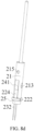
FIG. 2 is a three-dimensional view of an atomization assembly according to an embodiment of this application; -
FIG. 3 is an exploded view of the atomization assembly according to an embodiment of this application; -
FIG. 4 is a cross-sectional view of the atomization assembly according to an embodiment of this application; -
FIG. 5 is a three-dimensional view of a sleeve according to an embodiment of this application; -
FIG. 6 is a three-dimensional view of an insulation base according to an embodiment of this application; -
FIG. 7 is a three-dimensional view of a heating element according to an embodiment of this application; -
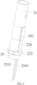
FIG. 8a is a schematic diagram of assembly step 1 of the atomization assembly according to an embodiment of this application; -
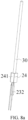
FIG. 8b is a schematic diagram of assembly step 2 of the atomization assembly according to an embodiment of this application; -
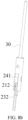
FIG. 8c is a schematic diagram of assembly step 3 of the atomization assembly according to an embodiment of this application; and -
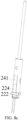
FIG. 8d is a schematic diagram of assembly step 4 of the atomization assembly according to an embodiment of this application. - For ease of understanding this application, this application is described below in more detail with reference to accompanying drawings and specific implementations.
- It should be noted that all the directional indicators (for example, upper, lower, left, right, front, rear, horizontal, and vertical) in the embodiments of this application are merely used to explain a relative position relationship, a motion status, and the like between components in a specific state (as shown in the accompanying drawings). If the specific state changes, the directional indicator correspondingly changes, the "connection" may be direct connection or indirect connection, and the "arranged", "arranged in", and "provided in" may be direct or indirect.
- In addition, descriptions involving "first", "second", and the like in this application are merely used for a purpose of description, and shall not be understood as an indication or implication of relative importance or implicit indication of a quantity of indicated technical features. Therefore, a feature defined by "first" or "second" can explicitly or implicitly include at least one of the features.
- This application provides an aerosol generation apparatus, including a liquid storage component, an atomization assembly, a power supply assembly, and other support assemblies. The power supply assembly mainly includes a battery and an airflow sensing switch assembly. The battery is electrically connected to the atomization assembly, to provide electric drive for the atomization assembly. The liquid storage component may be formed by a part of an inner cavity of a housing of the aerosol generation apparatus, or may be a separate liquid storage container. A liquid substrate stored in the liquid storage component can flow to the atomization assembly, and the atomization assembly atomizes the liquid substrate to generate an aerosol. Based on different liquid substrates stored in the liquid storage component, aerosol generation apparatuses may be classified into electronic cigarettes and medical equipment. The liquid substrate stored in the electronic cigarettes generally includes nicotine products. After being atomized, the liquid substrate stored in the medical equipment can generate an aerosol with therapeutic effects on respiratory diseases.
- The aerosol generation apparatus may be configured as two detachably connected assemblies. One assembly is an atomizer, and the other one is a power supply assembly. Such aerosol generation apparatus is referred to as an aerosol generation apparatus of a replaceable atomizer type. The power supply assembly includes a rechargeable battery, and a control module may be further arranged in the power supply assembly. The atomizer mainly includes the atomization assembly and a liquid storage component. After the liquid substrate is consumed, a service life of the atomizer ends, and a new atomizer can be connected to the power supply component for use. In another embodiment, the aerosol generation apparatus is configured as a whole, and the battery and the atomization assembly are accommodated in one housing. Such aerosol generation apparatus is generally referred to as a disposable aerosol generation apparatus. The disposable aerosol generation apparatus has a small volume and is convenient for users to carry.
- A cylindrical disposable aerosol generation apparatus is used as an example to briefly describe an internal structure thereof. Referring to
FIG. 1 , the aerosol generation apparatus includes ahousing 10. From the outside, amouthpiece 11 that is substantially flat is arranged at one end of thehousing 10. During use of the aerosol generation apparatus, the mouth of a user is mainly in contact with themouthpiece 11. Therefore, in a preferred implementation, themouthpiece 11 is made of a material at a high safety level. In an optional implementation, themouthpiece 11 and thehousing 10 may alternatively be integrally formed. Abottom cover 12 is connected to the other end of thehousing 10. Components in thehousing 10 are mainly mounted through an exposure at the other end of thehousing 10, and after the components are mounted, thebottom cover 12 is connected at the exposure of thehousing 10. - An
atomization assembly 20, abattery 51, anairflow sensing switch 52, and other components are mounted in thehousing 10. A part of an inner cavity of thehousing 10 is set as a liquid storage cavity 13 for storing a liquid substrate. The liquid storage cavity 13 is defined and formed by an independent liquid storage tube 131 provided in thehousing 10. The liquid storage tube 131 is filled with a capillary element with excellent liquid storage performance, and the liquid substrate is stored in the capillary element. The capillary element includes fiber cotton. Further, theatomization assembly 20 is arranged in the inner cavity of the liquid storage tube 131, and the capillary element is arranged around theatomization assembly 20. Anupper end cover 141 and alower end cover 142 are separately connected to two ends of the liquid storage tube 131. Theupper end cover 141 and thelower end cover 142 are in threaded connection to the liquid storage tube 131. - A part of the
mouthpiece 11 is accommodated in the inner cavity of thehousing 10. Amouthpiece port 110 is provided at one end of themouthpiece 11. One end of themouthpiece 11 accommodated in the inner cavity of thehousing 10 abuts against theupper end cover 141, and themouthpiece 11 has anair outlet chamber 111 in communication with themouthpiece port 110 inside. Anair outlet tube 15 is arranged at one end of theatomization assembly 20. A part of theair outlet tube 15 extends longitudinally in the liquid storage tube 131 and penetrates theupper end cover 141. An air outlet end of theair outlet tube 15 is in communication with theair outlet chamber 111 in themouthpiece 11. An aerosol generated in theatomization assembly 20 can enter theair outlet tube 15, and be guided by theair outlet tube 15 to enter themouthpiece 11, and inhaled by the user through themouthpiece port 110. The other end of theatomization assembly 20 is fixed on thelower end cover 142. At least a part of thelower end cover 142 defines and forms an air inlet channel. External air enters the inner cavity of theatomization assembly 20 through the air inlet channel. - In the disposable aerosol generation apparatus, the
atomization assembly 20 and the liquid storage tube 13 are accommodated in the inner cavity on an upper part of thehousing 10, and abattery 51 and anairflow sensing switch 52 are mainly arranged in the inner cavity on a lower part of thehousing 10. Theatomization assembly 20 is electrically connected to thebattery 51 and theairflow sensing switch 52. One end of thehousing 10 away from themouthpiece 11 is exposed, to facilitate mounting of components such as the liquid storage tube 13 and thebattery 51. After the components in thehousing 10 are mounted, the bottom cover is mounted at an exposed end of thehousing 10. Theairflow sensing switch 52 is mounted on thebottom cover 12. An air inlet is provided on thebottom cover 12. The external air enters the inner cavity of thehousing 10 through the air inlet. - Referring to
FIG. 2 to FIG. 7 , theatomization assembly 20 includes asleeve 21, aninsulation base 22, a heating element, and aliquid guide element 24. Theheating element 23 includes aheating portion 231 and aconductive portion 232. Theconductive portion 232 is electrically connected to the power supply assembly, to supply power to theheating portion 231. In an example, referring toFIG. 7 , theheating portion 231 is preferably made of a heating sheet with a mesh structure. Twoconductive portions 232, namely, a first conductive portion 233 and a second conductive portion 234, are separately arranged at two ends of the heating sheet. Theconductive portion 232 includes aconductive pin 2321 and aconductive lead 2322. An insulation sheath is sleeved outside a part of theconductive pin 2321 to form theconductive lead 2322. The heating sheet includes two free sides, namely, a first free side and a second free side. During mounting, the heating sheet encloses to form an unclosed tube-like structure. The two free sides of the heating sheet are connected to twoconductive pins 2321. The first free side of the heating sheet is connected to a first conductive pin, and the second free side is connected to a second conductive pin. The two free sides of the heating sheet are spaced apart to prevent a short circuit due to contact between the first conductive pin and the second conductive pin. - The
sleeve 21 has a hollowaccommodating cavity 211. Theheating portion 231 of theheating element 23 is accommodated in theaccommodating cavity 211. One part of theconductive portion 232 on each side of theheating portion 231 is accommodated in theaccommodating cavity 211, and the other part of theconductive portion 232 extends to an exterior of theaccommodating cavity 211. The part of theconductive portion 232 extending to the exterior of theaccommodating cavity 211 is mainly set in a form of theconductive lead 2322, to avoid a short circuit due to contact between theconductive portion 232 and other metal components or contact between the twoconductive portions 232. The first conductive portion 233 includes a firstconductive lead 2331, and the second conductive portion 234 includes a secondconductive lead 2341. - The
insulation base 22 is connected to the other end of thesleeve 21. Theinsulation base 22 is preferably made of a plastic material. Aperforation 221 is provided on theinsulation base 22, to fix the firstconductive lead 2331 and the secondconductive lead 2341 of theheating element 23. In an example provided in this application, only oneperforation 221 is provided on theinsulation base 22. The firstconductive lead 2331 and the secondconductive lead 2341 are fixed without being bent or pulled to outer sides of the two free sides of theheating portion 231, and can be kept relatively upright and relaxed to be inserted into theperforation 221. A distance between the firstconductive lead 2331 and the secondconductive lead 2341 is not greater than a distance between the two free sides of the heating sheet, so that a main portion of the heating sheet is always in a relaxed state in a process of fixing the firstconductive lead 2331 and the secondconductive lead 2341. In a preferred embodiment, the distance between the firstconductive lead 2331 and the secondconductive lead 2341 is equal to the distance between the two free sides of the heating sheet, so that the firstconductive lead 2331 and the secondconductive lead 2341 do not need to be positioned again with respect to the main portion of the heating sheet in the process of fixing, and relative positions between the main portion of the heating sheet and theliquid guide element 24 can be positioned according to a preset operation. It can be understood that if a positioned distance between the firstconductive lead 2331 and the secondconductive lead 2341 is greater than the distance between the two free sides of the heating sheet, during assembly, the firstconductive lead 2331 and the secondconductive lead 2341 need to be positioned again with respect to theheating portion 231 of the heating sheet. For example, the firstconductive lead 2331 and the secondconductive lead 2341 are bent and then fixed in theperforation 221 of theinsulation base 22. The firstconductive lead 2331 and the secondconductive lead 2341 of the heating sheet are positioned again, to form an expanding tension on theheating portion 231 of the heating sheet, to distort a fixed shape of the heating sheet, so that an effect of transferring the liquid substrate between theliquid guide element 24 and theheating element 23 is affected, and local resistance of theheating portion 231 of theheating element 23 is affected, thereby affecting uniformity of the entire heating efficiency of the heating sheet. - A
flange 222 extending circumferentially is provided on the insulation base. Theflange 222 divides the insulation base into two sections, where a first section located above theflange 222 can be accommodated in theaccommodating cavity 211 of thesleeve 21, and a fixingring 25 is sleeved outside a second section located below theflange 222. In some embodiments, the fixingring 25 is riveted on an outer wall of the second section of theinsulation base 22, so that theconductive lead 2322, after being squeezed, can firmly run through theperforation 221 of theinsulation base 22 without shaking. In other examples, after the firstconductive lead 2331 and the secondconductive lead 2341 run through theperforation 221 of theinsulation base 22, the firstconductive lead 2331 and the secondconductive lead 2341 may alternatively be firmly positioned in theperforation 221 by using glue. - A through
hole 223 is further provided on theinsulation base 22, and the throughhole 223 is in communication with theaccommodating cavity 211 of thesleeve 21. An external airflow can enter theatomization assembly 20 through the throughhole 223 of theinsulation base 22. In a preferred embodiment, theperforation 221 is provided on one side of the throughhole 223. A size of theperforation 221 is configured to accommodate twoconductive leads 2322. Specifically, a raisedrib 224 is provided on one side of theinsulation base 22. An inner space of therib 224 defines and forms theperforation 221. A raised height of therib 224 is substantially determined by an inner diameter of theperforation 221. Therib 224 substantially includes two sections. A first section of therib 224 is provided above theflange 222, and a second section of therib 224 is provided below theflange 222. - The
perforation 221 and the throughhole 223 are both provided in theinsulation base 22, and both extend by substantially the same distance in a longitudinal direction of theinsulation base 22. Therefore, theperforation 221 is provided close to the throughhole 223. In a preferred implementation, an axial projection region of the throughhole 223 can substantially coincide with an axial projection region of an unclosed tubular space formed by theheating portion 231 of theheating element 23, and theperforation 221 is substantially flush with a spacing region between the two free sides of theheating portion 231 of theheating element 23 in a longitudinal direction, so that theconductive portion 232 of theheating element 23 can be kept relatively upright to be directly inserted into theperforation 221. To facilitate theconductive lead 2322 to run into theperforation 221 and be fixed in theperforation 221, only aseparation wall 225 is arranged between theperforation 221 and the throughhole 223. A part of theconductive pin 2322 located above theseparation wall 225 can be kept relatively free to enter theperforation 221, and theseparation wall 225 supports theconductive lead 2322, so that theconductive lead 2322 can be kept relatively upright to be fixed in theperforation 221. To facilitate the lead to run out of theperforation 221, two notches are provided at a bottom end of theperforation 221 of theinsulation base 22. The notches are provided on two sides of therib 224, and are located below theflange 222. To avoid position interference for theheating portion 231 of theheating element 23 caused by unfirm fixing of a lower end of theconductive lead 2322, after theconductive lead 2322 runs out of theperforation 221, the fixingring 25 is riveted to a lower end of theflange 222 of theinsulation base 22, so that theconductive lead 2322 can be firmly fixed in theperforation 221. Due to the fixingring 25, theconductive lead 2322 is fixed in theperforation 221 without glue, and operations are easier and more convenient. - In a preferred implementation, the
heating portion 231 of theheating element 23 encloses to form an unclosed and substantially tube-like atomization cavity. A central axis of the atomization cavity, a central axis of theaccommodating cavity 211 of thesleeve 21, and a central axis of the throughhole 223 of theinsulation base 22 coincide. During mounting of theatomization assembly 20, accurate positioning of a central axis direction can be performed by using a substantially rod-like cotton-wrapped stick. An outer diameter of the cotton-wrapped stick is the same as the inner diameter of the throughhole 223 of theinsulation base 22. - The
liquid guide element 24 is preferably made of fiber cotton. During mounting, theliquid guide element 24 is arranged at a periphery of theheating element 23. In some embodiments, theliquid guide element 24 is formed by several liquid guide cotton sheets. After the several liquid guide cotton sheets are stacked, the liquid guide cotton sheets enclose the periphery of theheating element 23, and two free sides of the liquid guide cotton sheets are kept together to form a protrudingstructure 241. Theliquid guide element 24 is fixed through the protrudingstructure 241. In other embodiments, theliquid guide element 24 is a liquid guide body with a specific thickness. A hollow inner cavity is provided in theliquid guide element 24, and theheating element 23 is fixed in the inner cavity of theliquid guide element 24. A protrudingstructure 241 is provided on a side portion of the liquid guide body. The protrudingstructure 241 is also used for fixing theliquid guide element 24. - To facilitate the
liquid guide element 24 with the specific thickness to be fixed in thesleeve 21 more easily, aU-shaped opening 212 is provided on thesleeve 21, so that theliquid guide element 24 can be inserted into thesleeve 21 through a side portion of theU-shaped opening 212. Further, the protrudingstructure 241 on theliquid guide element 24 is fixed on theU-shaped opening 212, and theliquid guide element 24 is in fluid communication with the liquid storage cavity 13 through theU-shaped opening 212. Thesleeve 21 has a first end and a second end provided oppositely. Theinsulation base 22 is fixed at the second end of thesleeve 21. TheU-shaped opening 212 extends longitudinally to the second end of thesleeve 21. In some embodiments, referring toFIG. 5 , thesleeve 21 has afirst opening 2121 and asecond opening 2122 provided oppositely. Configurations of thefirst opening 2121 and thesecond opening 2122 enable the second end of thesleeve 21 to open at a specific angle, so that thesleeve 21 can be directly sleeved outside theliquid guide element 24. - An upper end of the
liquid guide element 24 abuts longitudinally against an end portion of theU-shaped opening 212 of thesleeve 21, and a lower end of theliquid guide element 24 abuts longitudinally against an upper end surface of therib 224 of theinsulation base 22. A width of therib 224 on theinsulation base 22 is equal to a width of theopening 212 of thesleeve 21. A longitudinally extending length of theU-shaped opening 212 of thesleeve 21 is configured to fix the protrudingstructure 241 of theliquid guide element 24 and the first section of therib 224 of theinsulation base 22. - An embodiment of this application further provides an assembly method for a
tubular atomization assembly 20. Refer toFIG. 8a to FIG. 8d :
Step 1, asheet heating element 23 is disposed on aliquid guide element 24, a cotton-wrappedstick 30 is disposed on theheating element 23, and the cotton-wrapped cotton is wrapped with liquid guide cotton manually, to form a first assembly, as shown inFIG. 8a . Theheating element 23 is placed at an intermediate position of theliquid guide element 24. A size of the cotton-wrapped stick is sufficiently large, so that theheating element 23 can only partially wrap the cotton-wrappedstick 30, andconductive portions 232 on two sides of theheating element 23 can attach to the cotton-wrappedstick 30. - Step 2, the first assembly is inserted from a U-shaped opening of a
sleeve 21, until a protrudingstructure 241 of theliquid guide element 24 engages with theU-shaped opening 212 of thesleeve 21, to form a second assembly, as shown inFIG. 8b . - Step 3, the protruding
structure 241 on theliquid guide element 24 of the second assembly is aligned with arib 224 of aninsulation base 22, until an end portion of the second assembly abuts against aflange 222 of theinsulation base 22, to form a third assembly, as shown inFIG. 8c . - Step 4, a fixing
ring 25 is riveted on theinsulation base 22 of the assembly 3, as shown inFIG. 8d . In a riveting process, the fixingring 25 squeezes theinsulation base 22, to tightly press aconductive lead 2322, so that theconductive lead 2322 can be firmly positioned in theperforation 221. - In addition, because positioning is performed substantially based on structures of components in processes of the above steps, automated assembly can be implemented. A
positioning hole 215 facilitating fixing a clamp for automated assembly may be provided on thesleeve 21. - After the assembly is completed, the
atomization assembly 20 is mounted in the liquid storage tube 131 in thehousing 10. After a sufficient liquid substrate fills the liquid storage tube 131, the cotton-wrappedstick 30 is taken out. In the entire mounting and assembly process of theatomization assembly 20, theheating portion 231 of theheating element 23 always wraps the cotton-wrappedstick 30, and the cotton-wrappedstick 30 can provide a radial support force for theheating element 23, so that a position of theheating element 23 can maintain relatively stable. - The
liquid guide element 24 is in communication with the liquid substrate in the liquid storage tube through afirst opening 2121 and asecond opening 2122 on thesleeve 21. In some examples, a separateliquid inlet hole 213 is further provided on thesleeve 21, and is located between thefirst opening 2121 and thesecond opening 2122, to further increase contact ways between the liquid substrate and theliquid guide element 24. For a liquid substrate with poor fluidity, a plurality of liquid inlet holes 213 may be provided on thesleeve 21. - The
conductive lead 2322 of theatomization assembly 20 may be directly electrically connected to abattery 51 and anairflow sensing switch 52 in ahousing 10 of an aerosol generation apparatus. It can be understood that theatomization assembly 20 may also be used in an aerosol generation apparatus of a replaceable atomizer type. Theatomization assembly 20 is mounted on the atomizer, an electrode column is arranged on abottom cover 12 of the atomizer, and twoconductive leads 2322 of theatomization assembly 20 are electrically connected to the electrode column. - When a length of the
sleeve 21 of theatomization assembly 20 is sufficiently long, one part of a space of thesleeve 21 accommodates theheating element 23 and theliquid guide element 24, the other part of the space of thesleeve 21 forms an air outlet channel, and the other end of thesleeve 21 extends to an interior of anair outlet chamber 111 of amouthpiece 11, to guide an aerosol to amouthpiece port 110. When the length of thesleeve 21 of theatomization assembly 20 is short, one end of thesleeve 21 may be connected to anair outlet tube 15. Theair outlet tube 15 may be sleeved outside thesleeve 21, or theair outlet tube 15 may be inserted into an inner cavity of thesleeve 21. - In the foregoing examples, the
heating element 23 is set as a heating sheet. Theliquid guide element 24 is arranged around theheating element 23. Theheating element 23 and theliquid guide element 24 are fixed in the inner cavity of thesleeve 21 in a longitudinal direction of thehousing 10. Theconductive lead 2322 of the heating element is fixed on theinsulation base 22 at the lower end of thesleeve 21. Theperforation 221 is provided on theinsulation base 22, and can accommodate twoconductive leads 2322 at the same time, and the twoconductive leads 2322 can be kept relatively relaxed to be inserted into thesame perforation 221 without bending. The fixing of theconductive lead 2322 does not apply a pulling force to a main portion of theheating element 23, so that theheating element 23 can be fixed in theliquid guide element 24 in a predetermined manner. In other examples, theheating element 23 may alternatively be set as a heating wire. The heating wire is wound around theliquid guide element 24 that is substantially rod-like. Two ends of the heating wire are connected toconductive pins 2321. Theconductive pins 2321 are fixed on theinsulation base 22 at the lower end of thesleeve 21 in a form of theconductive lead 2322. Optionally, theliquid guide element 24 may alternatively be a ceramic tube. Theheating element 23 is fixed in the inner cavity having the ceramic tube in a form of the heating wire or the heating sheet. - It should be noted that, the specification of this application and the accompanying drawings thereof illustrate preferred embodiments of this application, but this application is not limited to the embodiments described in the specification. Further, a person of ordinary skill in the art may make improvements or variations according to the foregoing descriptions, and such improvements and variations shall all fall within the protection scope of the appended claims of this application.
Claims (19)
- A tubular atomization assembly, comprising:a heating element, comprising a heating portion and a conductive portion electrically connected to the heating portion, wherein the conductive portion comprises a first conductive portion and a second conductive portion, and the heating portion is connected between the first conductive portion and the second conductive portion;a sleeve, having a hollow accommodating cavity, wherein the heating portion is accommodated in the accommodating cavity, and at least a part of the conductive portion extends to an exterior of the accommodating cavity; andan insulation base, connected at one end of the sleeve, wherein the insulation base comprises a perforation, and the first conductive portion and the second conductive portion run through the perforation to be fixed on the insulation base.
- The atomization assembly according to claim 1, wherein the atomization assembly further comprises a fixing ring around an exterior of the insulation base.
- The atomization assembly according to claim 1 or 2, wherein the heating portion comprises a heating sheet with a mesh structure, and the heating portion is constructed into an unclosed tubular structure.
- The atomization assembly according to claim 3, wherein the first conductive portion comprises a first conductive lead, and the second conductive portion comprises a second conductive lead; and the first conductive lead and the second conductive lead are positioned on the insulation base, and a distance between the first conductive lead and the second conductive lead is not greater than a distance between two free sides of the heating element.
- The atomization assembly according to claim 4, wherein a spacing region is provided between the two free sides of the heating portion, and the perforation is substantially flush with the spacing region in a longitudinal direction.
- The atomization assembly according to claim 1, wherein at least one U-shaped opening is provided on a side surface of the sleeve.
- The atomization assembly according to claim 6, wherein the opening comprises a first opening and a second opening that are spaced apart; and at least one liquid inlet hole is further provided between the first opening and the second opening.
- The atomization assembly according to claim 6, wherein a rib is provided on the insulation base, and a size of the rib is configured to be inserted into the opening.
- The atomization assembly according to claim 8, wherein the rib is located at a position on an outer surface of the insulation base corresponding to the perforation.
- The atomization assembly according to claim 1, wherein the insulation base further comprises a through hole, and the through hole is coaxially provided with the accommodating cavity.
- The atomization assembly according to claim 10, wherein the perforation is provided on a side of the through hole, and a separation wall is arranged between the through hole and the perforation.
- The atomization assembly according to claim 6, further comprising a liquid guide element arranged at least partially around the heating element, wherein the liquid guide element comprises a protruding structure, and the protruding structure is accommodated in the opening.
- The atomization assembly according to claim 1 or 8, further comprising a liquid guide element arranged at least partially around the heating element, wherein the liquid guide element abuts longitudinally against the insulation base.
- The atomization assembly according to claim 13, wherein the liquid guide element comprises a protruding structure, and a size of the opening is configured to accommodate the protruding structure of the liquid guide element and at least a part of the rib of the insulation base.
- The atomization assembly according to claim 1 or 2, wherein the insulation base comprises a flange, and one end of the flange abuts against the sleeve.
- The atomization assembly according to claim 15, wherein the fixing ring abuts against the other end of the flange.
- An assembly method for the atomization assembly according to any one of claims 1 to 16, wherein the assembly method comprises: winding a heating element and a liquid guide element around a stick, to form a first assembly; inserting the first assembly into an accommodating cavity of a sleeve from one end of the sleeve; and connecting an insulation base to the same end of the sleeve, and accommodating two conductive portions of the heating element in a perforation of the insulation base.
- The assembly method for the atomization assembly according to claim 17, wherein the assembly method further comprises: riveting a fixing ring on the insulation base.
- An aerosol generation apparatus, comprising a housing, wherein a liquid storage cavity for storing a liquid substrate and an atomization assembly are arranged in the housing, wherein the atomization assembly comprises the atomization assembly according to any one of claims 1 to 16, and the atomization assembly atomizes the liquid substrate to generate an aerosol.
Applications Claiming Priority (2)
| Application Number | Priority Date | Filing Date | Title |
|---|---|---|---|
| CN202210052294.7A CN116491691A (en) | 2022-01-18 | 2022-01-18 | Atomization component and its assembly method, aerosol generating device |
| PCT/CN2023/071623 WO2023138443A1 (en) | 2022-01-18 | 2023-01-10 | Atomization assembly and assembly method therefor, and aerosol generation apparatus |
Publications (2)
| Publication Number | Publication Date |
|---|---|
| EP4445771A1 true EP4445771A1 (en) | 2024-10-16 |
| EP4445771A4 EP4445771A4 (en) | 2025-05-07 |
Family
ID=87317085
Family Applications (1)
| Application Number | Title | Priority Date | Filing Date |
|---|---|---|---|
| EP23742758.8A Pending EP4445771A4 (en) | 2022-01-18 | 2023-01-10 | Atomization assembly and assembly method therefor, and aerosol generation apparatus |
Country Status (5)
| Country | Link |
|---|---|
| US (1) | US20250098765A1 (en) |
| EP (1) | EP4445771A4 (en) |
| KR (1) | KR20240132514A (en) |
| CN (1) | CN116491691A (en) |
| WO (1) | WO2023138443A1 (en) |
Families Citing this family (1)
| Publication number | Priority date | Publication date | Assignee | Title |
|---|---|---|---|---|
| CN117338050B (en) * | 2023-11-23 | 2025-07-25 | 四川三联新材料有限公司 | Heating cigarette aerosol generating device |
Family Cites Families (14)
| Publication number | Priority date | Publication date | Assignee | Title |
|---|---|---|---|---|
| WO2013113173A1 (en) * | 2012-02-03 | 2013-08-08 | Maas Bernard Karel | Electronic simulatied cigarette and atomizer thereof |
| CN203435687U (en) * | 2013-08-31 | 2014-02-19 | 卓尔悦(常州)电子科技有限公司 | Atomizing head |
| CN204317504U (en) * | 2014-12-03 | 2015-05-13 | 深圳市合元科技有限公司 | Cure hot type electrical smoking device |
| JP6827424B2 (en) * | 2015-05-06 | 2021-02-10 | アルトリア クライアント サービシーズ エルエルシー | Non-combustible smoking device and its elements |
| CA3022310C (en) * | 2016-04-27 | 2021-07-27 | Japan Tobacco Inc. | Flavor inhaler cartridge and flavor inhaler |
| KR102116961B1 (en) * | 2017-07-21 | 2020-06-02 | 주식회사 아모센스 | heater assembly for cylinderical type electronic cigarette and cylinderical type electronic cigarette including the same |
| CN207821093U (en) * | 2017-12-11 | 2018-09-07 | 常州市派腾电子技术服务有限公司 | Atomizer and electronic cigarette |
| CN109638184A (en) * | 2018-11-21 | 2019-04-16 | 泰州市蓝天塑料制品厂 | A kind of fixed device of buried battery cable and its fixing means |
| GB201902220D0 (en) * | 2019-02-18 | 2019-04-03 | Nicoventures Trading Ltd | Aerosol provision systems |
| CN211153807U (en) * | 2019-08-21 | 2020-08-04 | 珠海惠友电子有限公司 | Ceramic heating component for heating non-combustible electronic cigarette and electronic cigarette |
| CN112770428A (en) * | 2021-01-25 | 2021-05-07 | 深圳市天翔宇科技有限公司 | Central heating device, heating rod and liquid heater |
| CN215347065U (en) * | 2021-06-23 | 2021-12-31 | 深圳市合元科技有限公司 | Heating assembly and smoking article including the same |
| CN113712273A (en) * | 2021-08-26 | 2021-11-30 | 深圳市赛尔美电子科技有限公司 | Atomization structure and manufacturing method thereof |
| CN217446654U (en) * | 2022-01-18 | 2022-09-20 | 深圳市合元科技有限公司 | Atomizing assembly and aerosol generating device |
-
2022
- 2022-01-18 CN CN202210052294.7A patent/CN116491691A/en active Pending
-
2023
- 2023-01-10 US US18/729,567 patent/US20250098765A1/en active Pending
- 2023-01-10 EP EP23742758.8A patent/EP4445771A4/en active Pending
- 2023-01-10 WO PCT/CN2023/071623 patent/WO2023138443A1/en not_active Ceased
- 2023-01-10 KR KR1020247027631A patent/KR20240132514A/en active Pending
Also Published As
| Publication number | Publication date |
|---|---|
| EP4445771A4 (en) | 2025-05-07 |
| CN116491691A (en) | 2023-07-28 |
| US20250098765A1 (en) | 2025-03-27 |
| KR20240132514A (en) | 2024-09-03 |
| WO2023138443A1 (en) | 2023-07-27 |
Similar Documents
| Publication | Publication Date | Title |
|---|---|---|
| CN217446654U (en) | Atomizing assembly and aerosol generating device | |
| EP3162226B1 (en) | Electronic cigarette | |
| EP3135135B1 (en) | Electronic smoking device with liquid reservoir/wick portion | |
| CA3095711C (en) | Vapour provision systems, liquid transport elements and vaporisers for vapour provision systems, and methods of assembly | |
| EP3829361B1 (en) | Electronic vaping device including transfer pads with oriented fibers | |
| JP2023145772A (en) | Heater for vapor provision system | |
| CN216315620U (en) | Heating assembly, atomizer and electronic atomization device | |
| WO2015071703A1 (en) | Atomizer unit for use in an electronic cigarette | |
| CN110652039A (en) | Electronic aerosol supply system and device for an electronic aerosol supply system | |
| WO2019193311A1 (en) | Vapour provision systems | |
| US20250098765A1 (en) | Atomization assembly and assembly method therefore, and aerosol generation apparatus | |
| WO2019145672A1 (en) | Vapour provision apparatus and systems | |
| CN216983574U (en) | Atomizing core unit, atomizer and aerosol generating device | |
| CN206547881U (en) | Smoke bomb and electronic cigarette with the same | |
| CN217184807U (en) | Nebulizer, atomizing core unit and aerosol generating device | |
| CN223415698U (en) | Electronic atomization device | |
| CN219982173U (en) | Atomizing core assembly, atomizer and electronic atomizing device | |
| CN222941792U (en) | Atomizer components and electronic atomizers | |
| EP4728902A1 (en) | Atomizer and electronic atomization device | |
| US20250212957A1 (en) | Atomizer and electronic atomization device | |
| EP4643682A1 (en) | Atomization assembly, atomizer, and electronic atomization device | |
| CN219982143U (en) | Atomizer, power supply assembly and electronic atomization device | |
| CN217446656U (en) | Aerosol generating device | |
| EP4487712A1 (en) | Aerosol product heating assembly and aerosol generation device | |
| RU2844591C2 (en) | Tubular spray assembly of an aerosol-generating device and a method for assembling same, an aerosol-generating device |
Legal Events
| Date | Code | Title | Description |
|---|---|---|---|
| STAA | Information on the status of an ep patent application or granted ep patent |
Free format text: STATUS: THE INTERNATIONAL PUBLICATION HAS BEEN MADE |
|
| PUAI | Public reference made under article 153(3) epc to a published international application that has entered the european phase |
Free format text: ORIGINAL CODE: 0009012 |
|
| STAA | Information on the status of an ep patent application or granted ep patent |
Free format text: STATUS: REQUEST FOR EXAMINATION WAS MADE |
|
| 17P | Request for examination filed |
Effective date: 20240708 |
|
| AK | Designated contracting states |
Kind code of ref document: A1 Designated state(s): AL AT BE BG CH CY CZ DE DK EE ES FI FR GB GR HR HU IE IS IT LI LT LU LV MC ME MK MT NL NO PL PT RO RS SE SI SK SM TR |
|
| REG | Reference to a national code |
Ref country code: DE Ref legal event code: R079 Free format text: PREVIOUS MAIN CLASS: A24F0040400000 Ipc: A24F0040460000 |
|
| DAV | Request for validation of the european patent (deleted) | ||
| DAX | Request for extension of the european patent (deleted) | ||
| A4 | Supplementary search report drawn up and despatched |
Effective date: 20250408 |
|
| RIC1 | Information provided on ipc code assigned before grant |
Ipc: A24F 40/10 20200101ALN20250402BHEP Ipc: A24F 40/70 20200101ALI20250402BHEP Ipc: A24F 40/46 20200101AFI20250402BHEP |